Load Lamp
Introduction
Load Lamp allows you to safely test your devices by limiting the current.
If you're making multiple changes to an electronic device, you can use the load lamp to help ensure everything is safe. For example, if you're worried that your changes might cause a short, you can watch the load lamp to see how bright it gets. This will help you understand if there are any issues in the system and avoid any unwanted blowing of fuses or shorting of expensive components.
However, this is easier said than done. There are two things to pay attention to.
- Voltage of the device under test. For example, is it a 120V device? or a 12V device
- Wattage typically consumed by the device under test. Example: is it a small radio that consumes 20W or a CRT that consumes 120W.
In this article, we will be testing devices that operate at 120 volts. For different wattages, we will be using different size lamps. We will also take a look at scenarios where the load lamp doesn't work.
How do you build one?
Luckily, constructing this tool is a straightforward process that can be accomplished with readily available components from your nearby hardware store, all within a budget of less than $50.
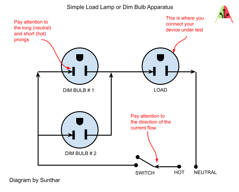
Here is a wiring diagram that demonstrates what I built.
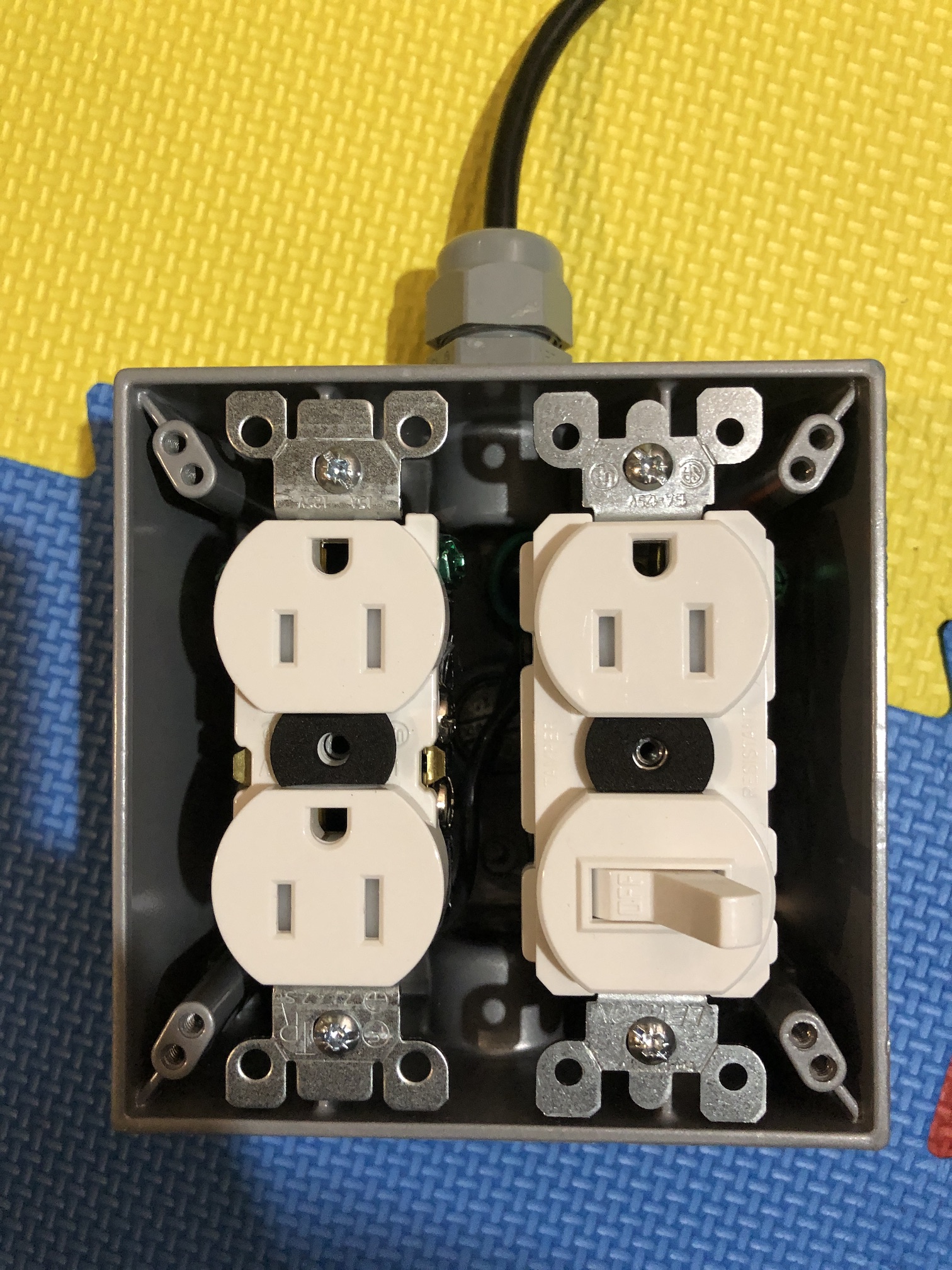
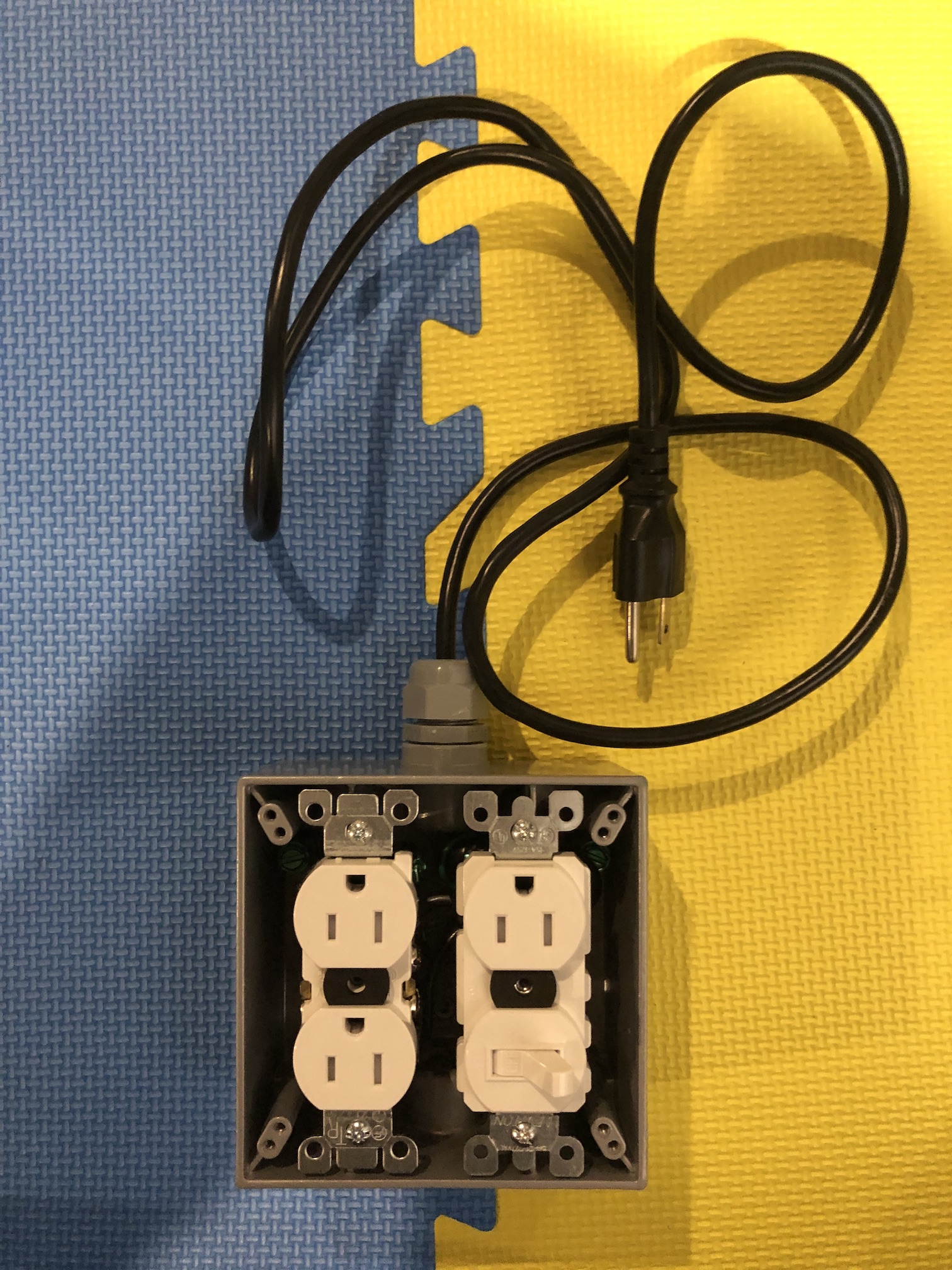
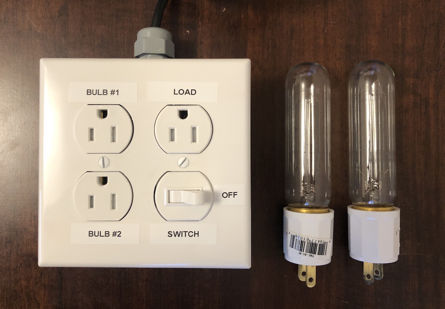
Pictures of the actual device
Parts used (in CAD$)
- Red Dot, Two gang die-cast aluminum grey outlet box with 3 x 1/2" hubs ($18.46)
- Leviton, Plug-In Socket Medium Base, White (2 units) ($5.37 x2 = $10.74)
- Leviton, 2-Gang Midway Nylon Duplex Receptacle Wallplate, in White ($2.96)
- Leviton, Duplex Tamper Resistant Receptacle, White ($1.61)
- Leviton, 15 Amp Combination Switch-Receptacle - White ($13.67)
- Carlon, 1/2 -in Cord Grip Connector ($5.99)
- Spare computer wire ($1)
Total cost: $61.50 CAD ($55 + tax)
The cost of this project doesn't include the light bulbs needed. You will need various bulbs with different wattages. For our testing, we will be using multiple 60 watt light bulbs.
Version 2 of load lamp
At times, it is nice to know when this device is active. It's even better if we can also see the operating voltage, especially when utilized alongside a variac or a 240V transformer. Additionally, having an approximate measure of amperage usage is also helpful. Fortunately, there's a solution for this.
In version 2, I incorporated a meter into the device. It accomplishes all of the above. Although the amperage reading may not be precise (in comparison to a Kill-A-Watt device), it still proves quite useful.
Here is the plan. 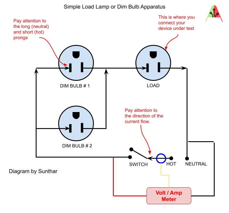
Had to move around some components on the meter to make it fit. 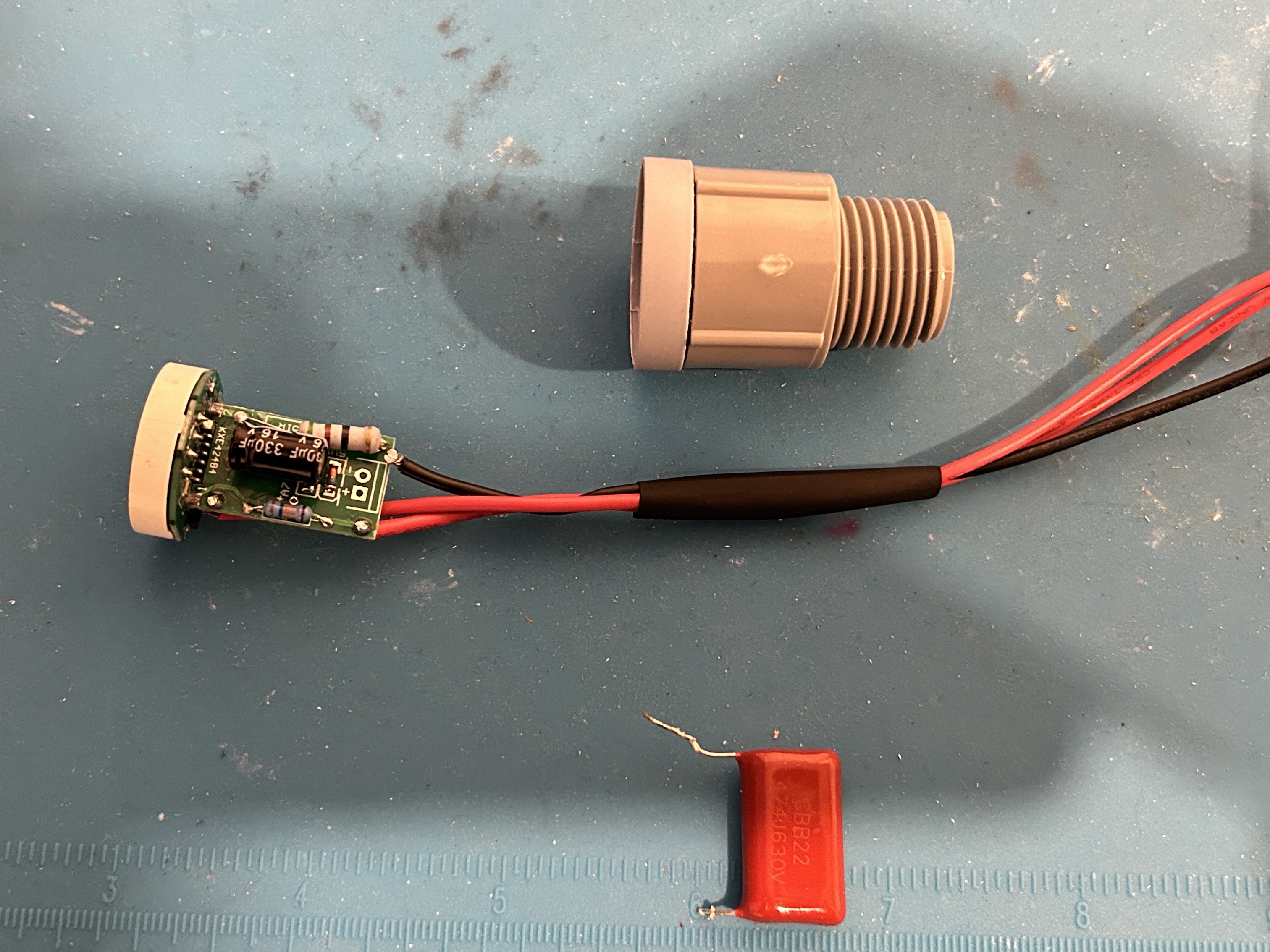
Used a 1/2" threaded pipe fitting to make it all snugly fit together. 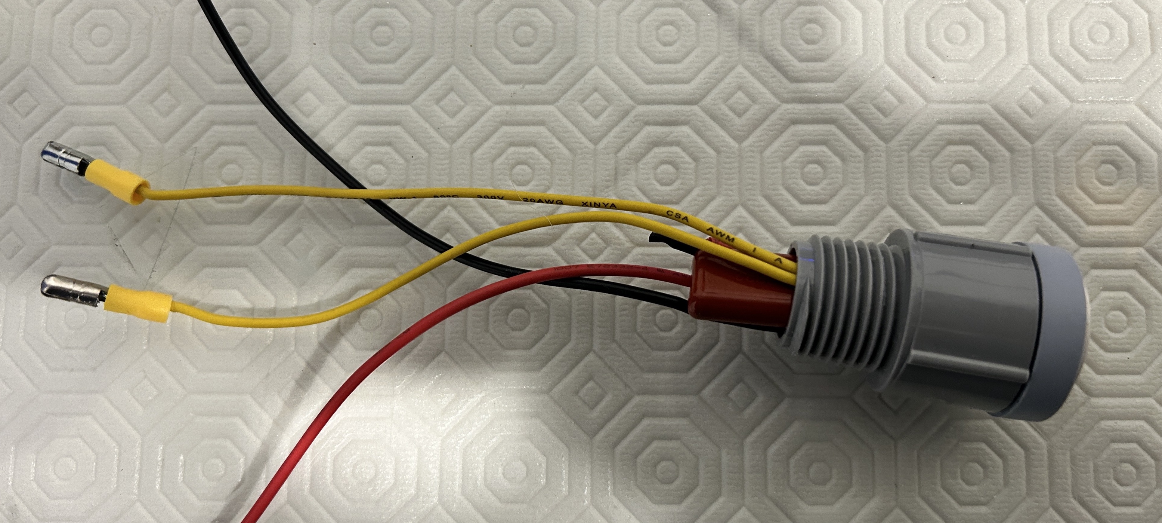
End result 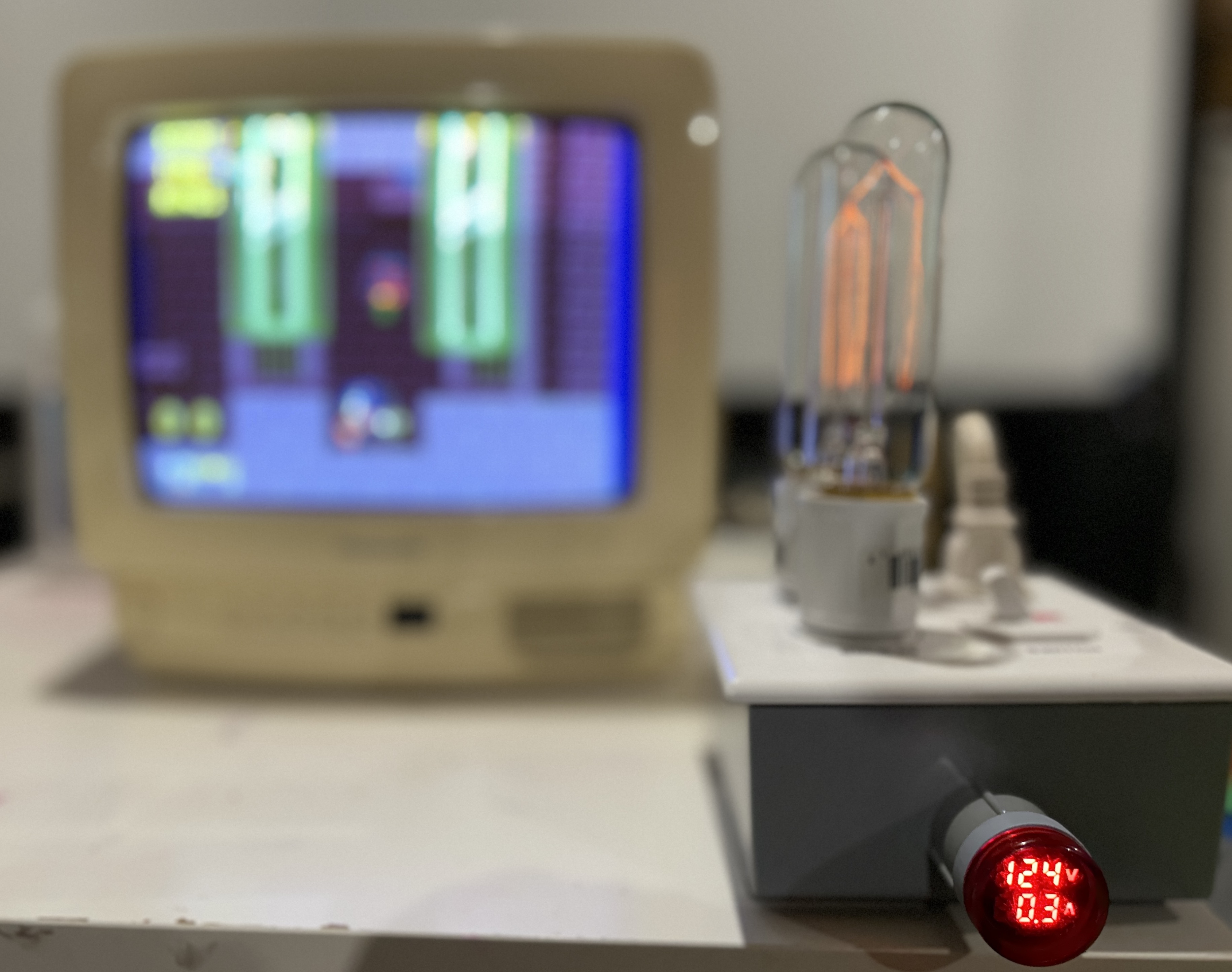
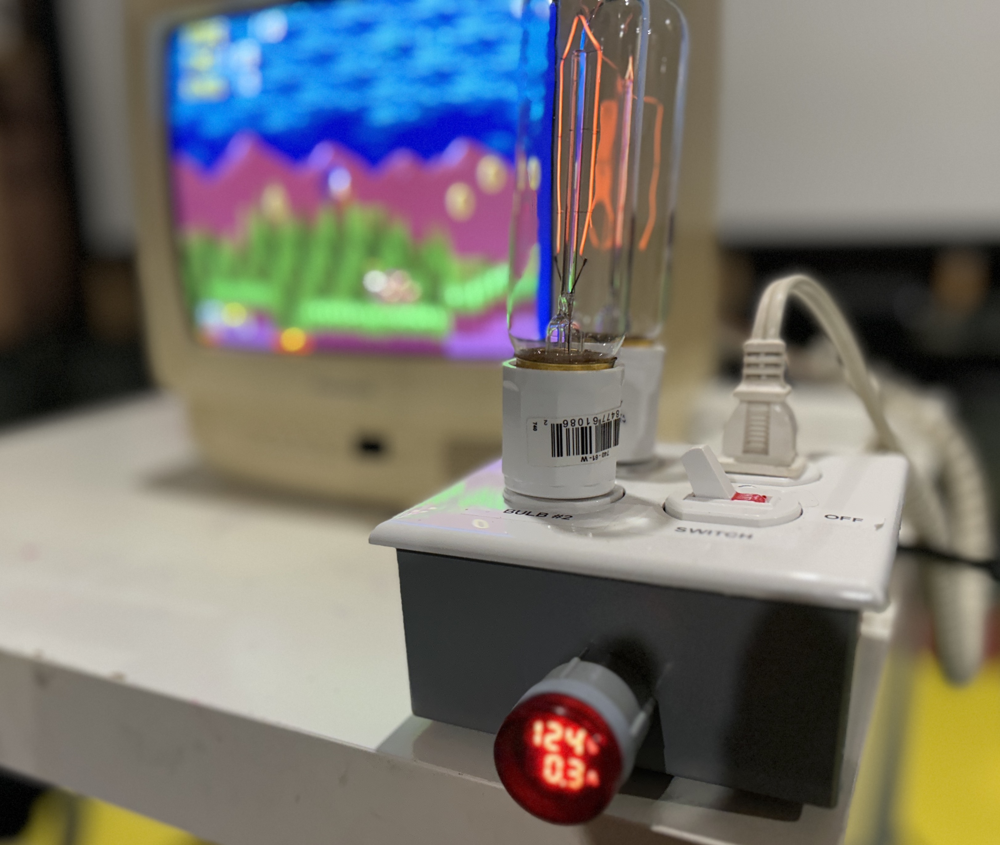
Let's take it for a test drive
Test #1 (KV-27V20)
I tested my power supply board on a Sony CRT TV, KV-27V20. This CRT had an AA-2D chassis, with a separate power supply board, which made it convenient to remove the power supply board for testing purposes. Unfortunately, this CRT did not power ON, as the HOT and several other components were shorted due to an oversight from my end.
The CRT was rated for 165W. However, with the power supply taken out seperately we don't need a 200W lamp to make the load lamp work. I attached one 60W lamp to the load lamp and powered on the power supply.
Dim bulb was bright for couple of seconds and then turned off. The dim bulbs were bright for those three seconds because the large capacitors on the primary side of the power supply were sucking in that initial current to charge up. This is a good sign. This means there are no shorts on the primary side of the power supply.
Then, I disconnected the power supply board and inspected for opens and shorts. Parts that needed attention are highlighted in pink boxes in the below schematics.
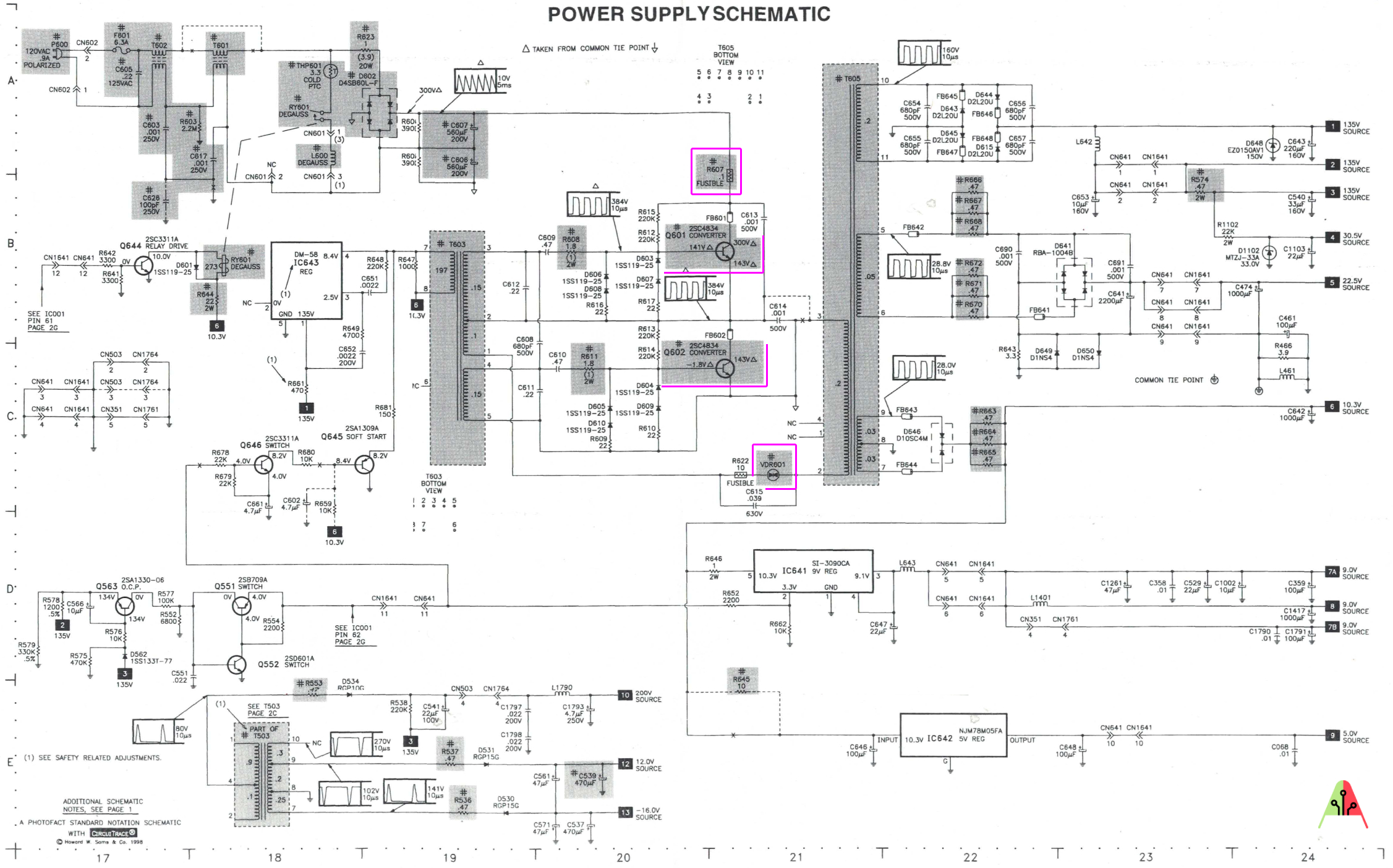 Click the above image to expand. This schematic was taken from KV-27S22.
R607(0.1Ω/0.5W fusible resistor) was open. This is a fuse type of resistor and if this is open, then secondary side doesn't get any power.Q601power transistor was shorted. If you change R607 and power on with the load lamp, you would expect the light to be bright. I did not try this though.Q602power transistor was shorted.VDR601Not sure how to test this, but this didn't seem to be impacted. Several maintenance notes mention it is best to change this if Q601 and Q602 are found to be shorted.
Replacing R607, Q601 and Q602 (2SC4834 transistors), all the rails got the correct voltages. [1,2,3] - 135V, [9] - 5V (Standby). Load lamp remained quiet after that initial blip, as the power supply board was disconnected and no current was being drawn.
Test #2 (KV-27V20)
Now it's time to find out if aynthing else is shorted before powering on the set. I already knew the HOT (2SC4907) was shorted, so didn't want to take a chance by powering on the set on even with the load lamp.
But, what if we did power it on? Let's look at the calculation for a second. If I powered on the set with 2x 60W bulbs, I will be allowing a maximum of 120W of power through the load lamp. 120W/120V = 1A. That is 1A of current.
Is this going to blow the fuse?
R607, our fusible resistor allows ~2.2A of current.
P = I^2 x R
I = SQRT (P/R)
I = SQRT (0.5/0.1)
  = 2.2A
Therefore, theoretically nothing should blow if powered on through a load lamp. Expected outcome here is bright lights. This will indicate a short and you will have time to turn off the set and diagnose the short. But, why take the chance when you already know the HOT is shorted. I decided to replace the HOT with a working HOT and then power the set on with the 2x 60W lamp.
These were the parts replaced. 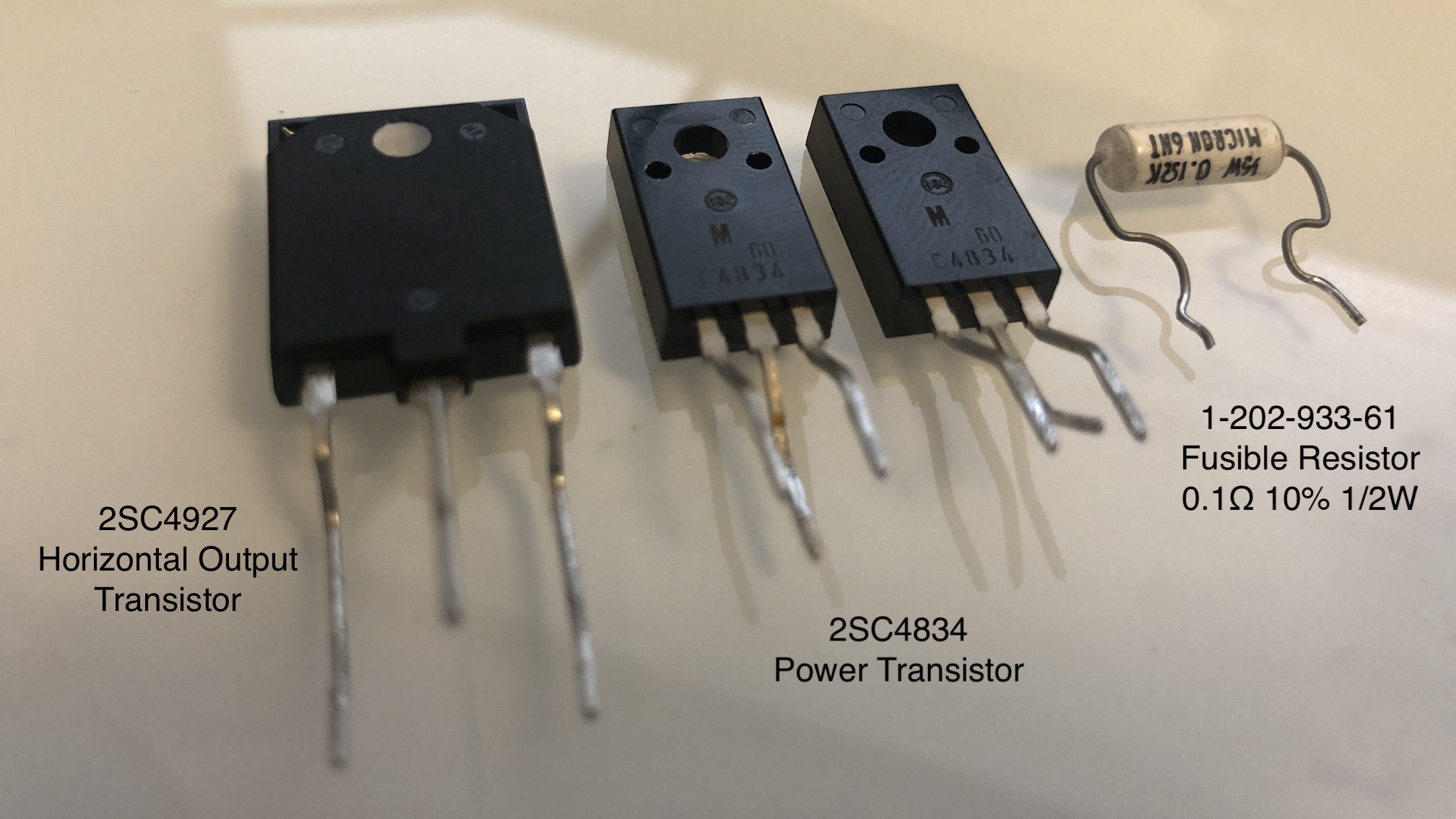
Subsequently, I proceeded to gradually increase the current supplied to the CRT TV by either adding more bulbs or using higher wattage bulbs. It is important to note that the degauss coil was disconnected during the following tests, while all other connections remained intact.
Here are the results of the tests:
- At 120W (1A), despite the CRT turning on, no raster appeared.
- At 160W (1.3A), after a 10-second delay, the raster finally appeared, albeit with a narrower width. The bulbs were fully illuminated.
- At 180W (1.5A), the raster significantly improved, while the bulbs remained fully lit.
- At 200W (1.6A), it seemed that the CRT was receiving the optimal amount of power, as the raster quality reached its best level.
Based on the above experiment, it becomes evident that it is crucial to ensure that the total wattage of the bulbs used is at least equal to the maximum wattage specified for your specific TV model.
Test #3 (Toshiba 14AF43)
This explains a scenario where the load lamp doesn't work.
Powered on the Toshiba AF series set (14" and 20") with the load lamp. It does not work.!
I tried with 2x 60W bulb and still no luck. Lights were bright indicating there is a short, even though the set did not have any shorts or issues when connected directly.
Apparently the load lamp doesn't work in cases where a PFC (Power Factor Correction) circuitry is present. PFC is a feature included in some computer and other power supply boxes that reduces the amount of reactive power generated by a computer. PFC circuitry draws a lot of power to start and because of the voltage drop present with the load lamp, PFC circuitry continuously tries to start. This keeps drawing a lot of power, which keeps the load lamp bright indicating there is a short. This video explains this very well. In this video he calls it a phantom fault.
