Sony CCD-TR91 Video8 Handycam
Ceramicized Sony CCD-TR91 Video8 Handycam
In this article we are going to restore the 1993 Sony CCD-TR91 camera with a slightly modern and experimental method. The idea is to completely replace the electrolytic caps to equivalent ceramic caps and see if the camera continues to function. The end outcome turned out to be successful, as the camera was able to film continuously for several hours without any issues. Also, I felt a sense of relief knowing that this 90s device was completely free of electrolytic capacitors.
Please proceed with the presented modifications at your own risk.
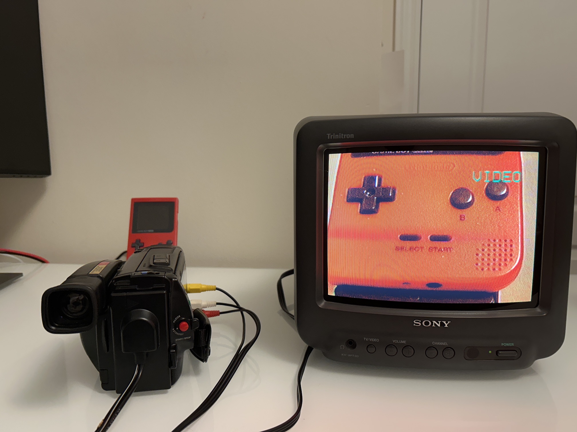
We'll try out zooming in and out, recording videos, rewinding, playing back, fast forwarding, and connecting the camera to a CRT TV through A/V, along with lots of other things that this camera is designed to do.
Background
Ever since I got interested in old TVs and vintage video games, I've been trying to find ways to have fun with electronics from the 1990s. And what could be better than trying out a Video8 camcorder, something I couldn't afford back in the '90s? I found a Sony CCD TR-91 on Kijiji (kind of like Canadian Craigslist). Someone was selling a broken camcorder for parts for just $10.
After going back and forth with the seller for several days and weeks, I finally decided to buy it since I was going to be in their neighborhood anyway. My plan was to use this camcorder to test replacing ceramic capacitors and get to play a Video8 cassette. I didn't expect much, but I was completely amazed by the results.
It took me a whole year to finish this project, but I'm happy that I eventually got it done.
Manuals
DO THIS AT YOUR OWN RISK
I'm sharing this article based on my personal experiments and perspectives. However, your circumstances might be entirely unique. For instance, a leaked capacitor could have harmed a crucial component, leading to corrosion or a short circuit that could potentially pose a fire hazard. Prior to taking any action, it's crucial to thoroughly assess your own situation and exercise caution.
Pictures of the camera
Viewfinder folded 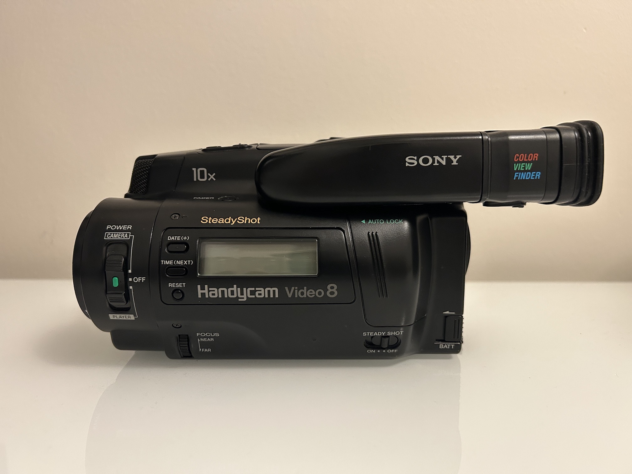
Viewfinder 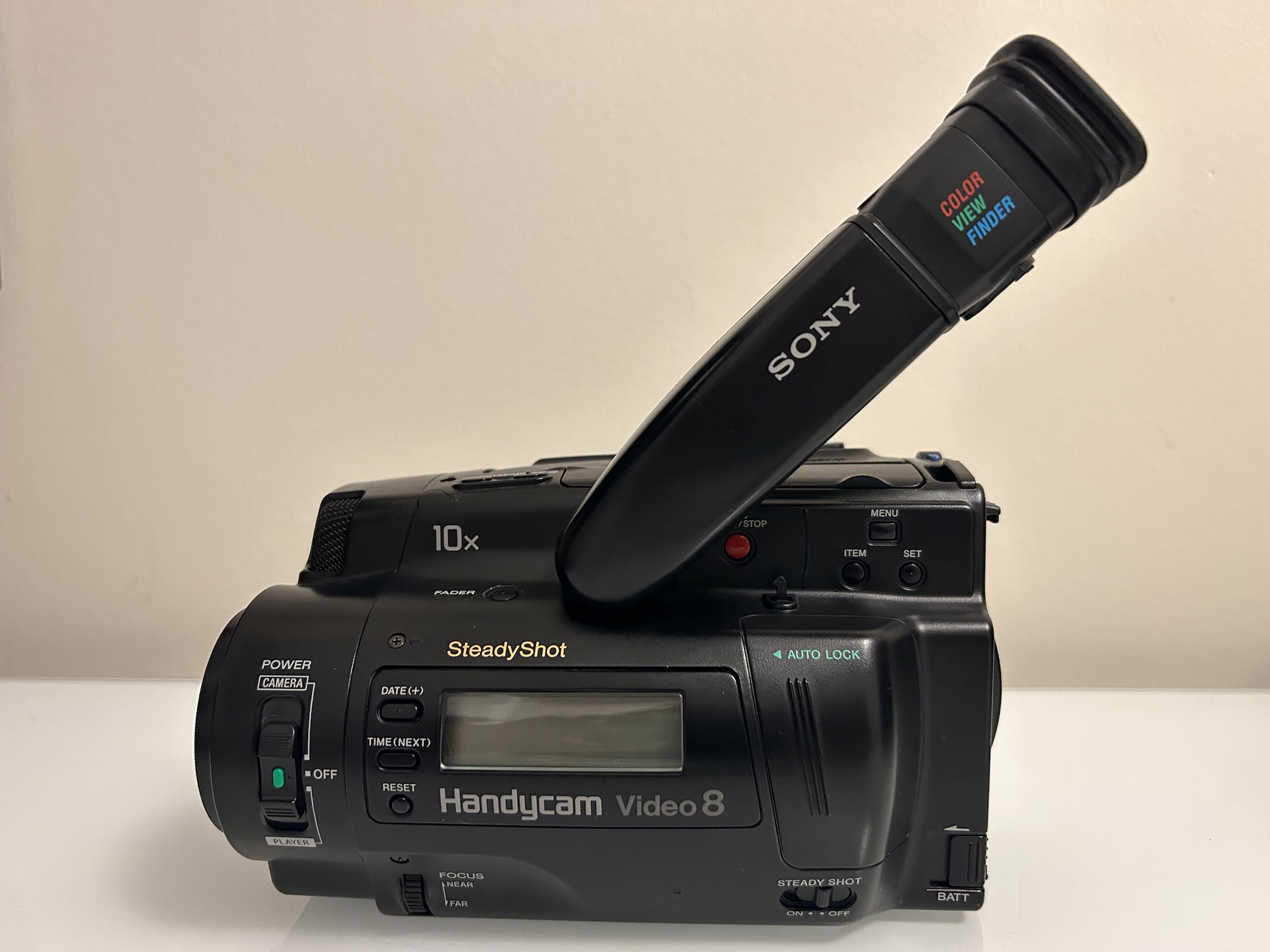
Front view 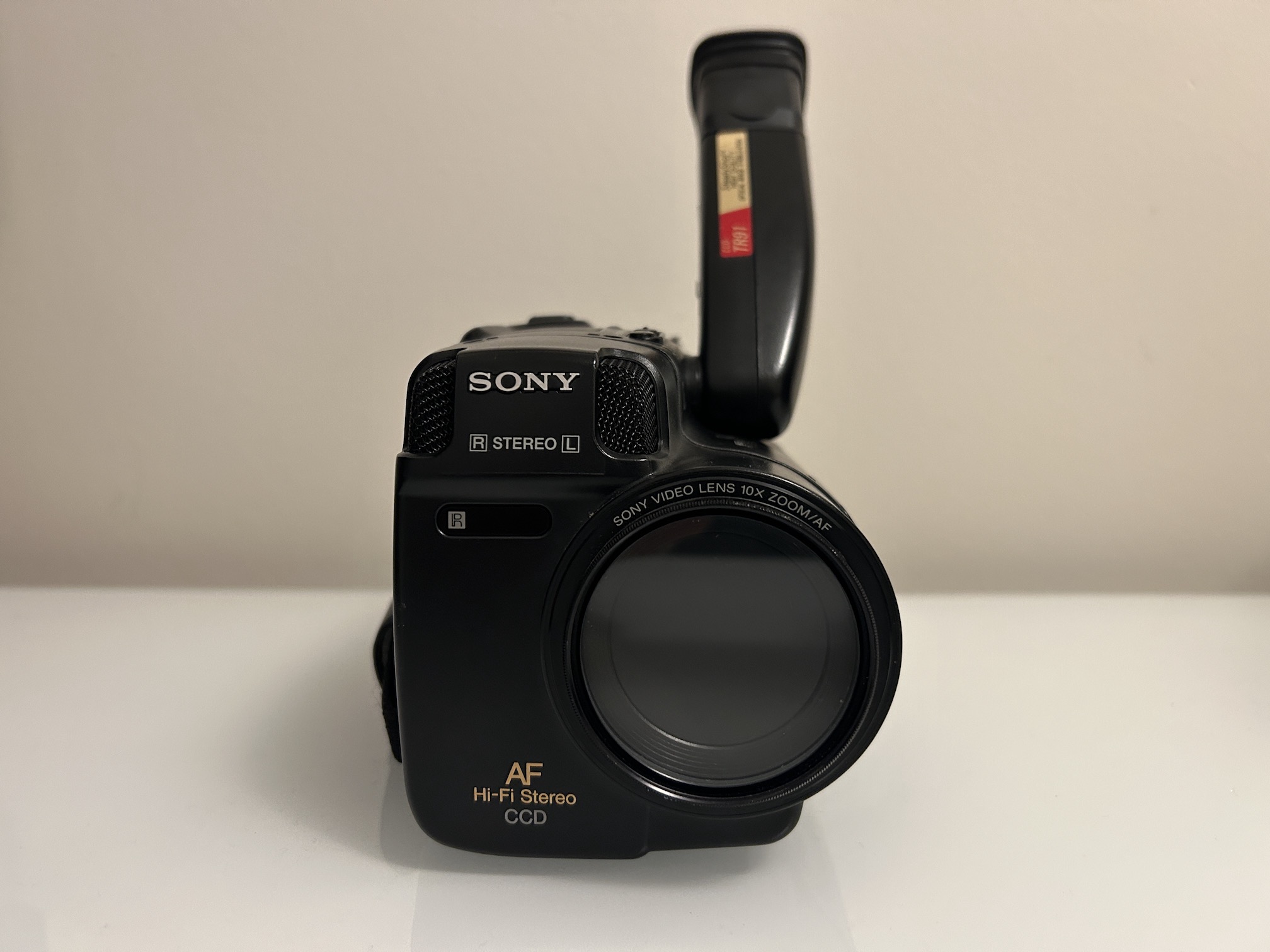
Right side view 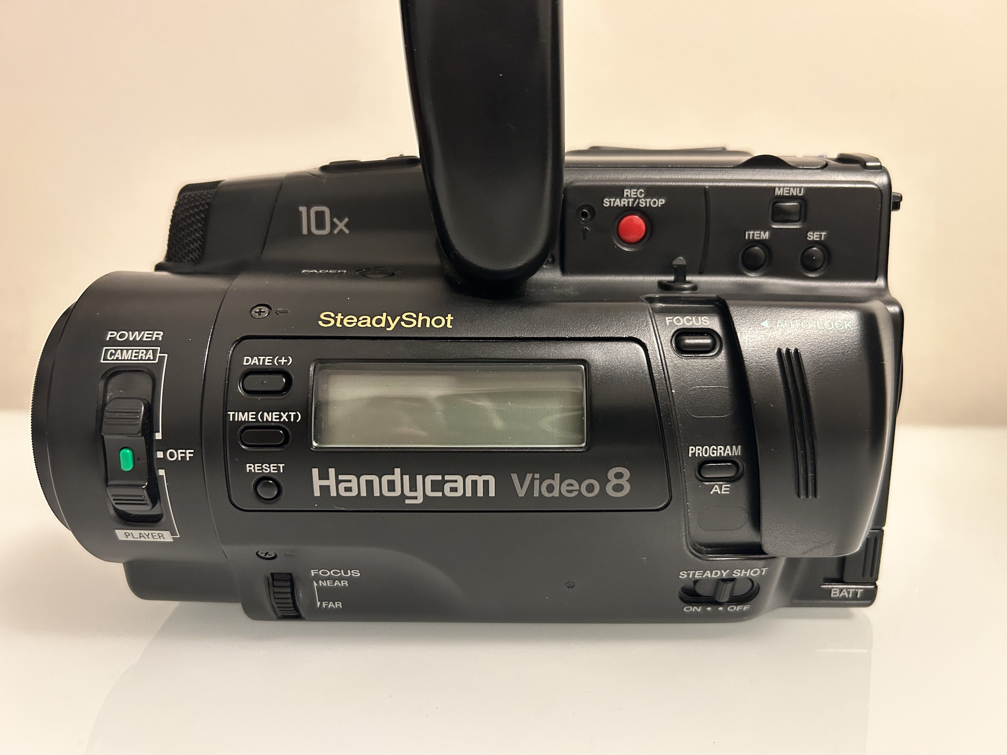
Left side view 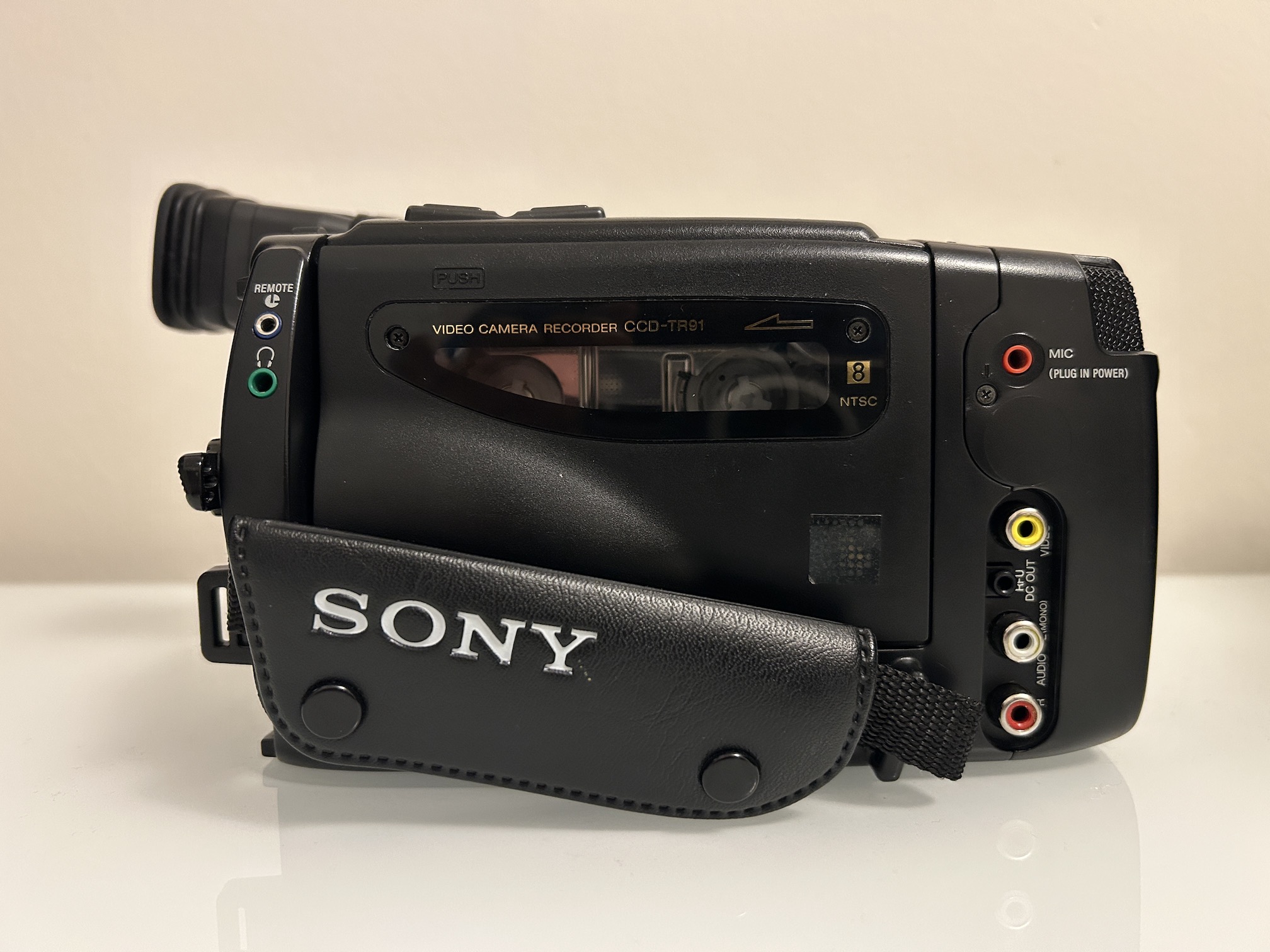
Top view 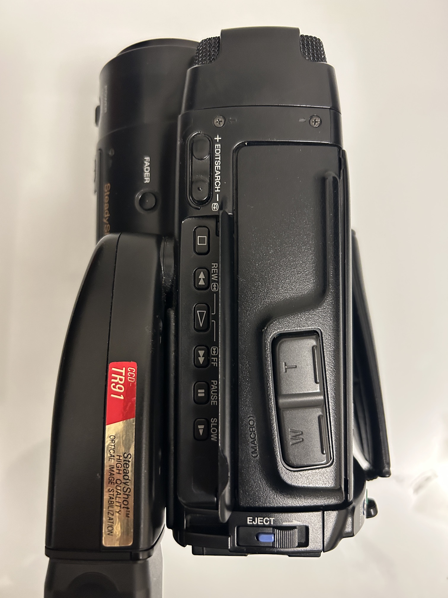
Let's open this
After removing the cabinet assembly 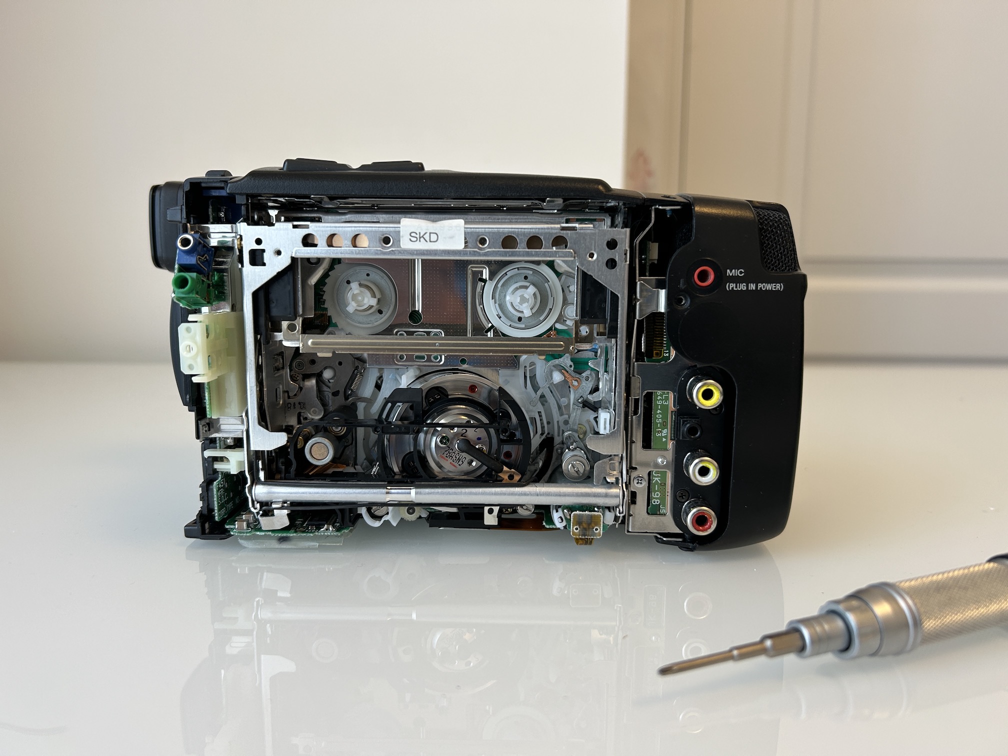
Baaaad capacitors
Many aluminum electrolytic capacitors made between mid 1990s and 2007 had a higher failure rate than expected. There's a whole wiki dedicated to this issue, so I won't go into the specifics.
READ BEFORE YOU CHANGE CAPS
You might feel like changing all the capacitors in a device, but it's usually not needed. I've checked capacitors in devices over 30 years old, and in many cases, they were still within specs. However, for this specific device, I recommend replacing all the capacitors because most of the ones I swapped out were either leaking or on the verge of leaking.
Circuit board location
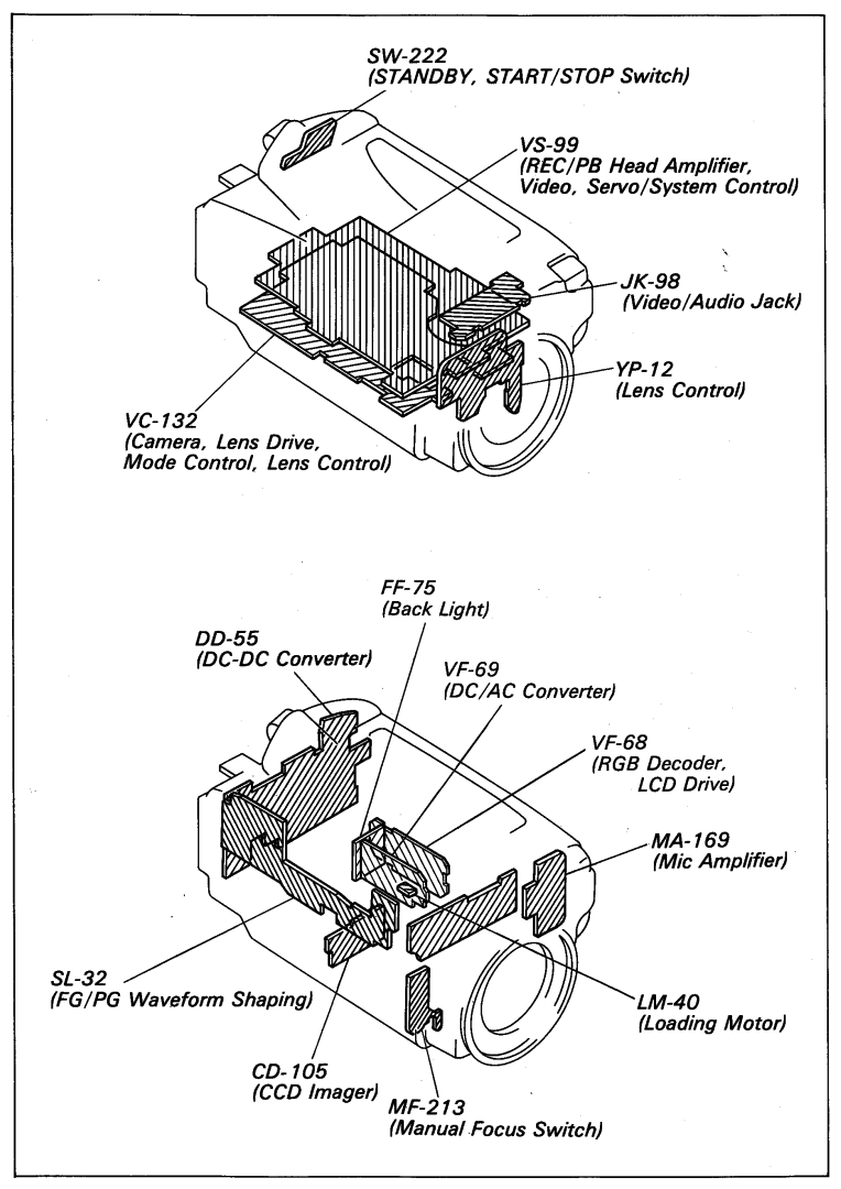
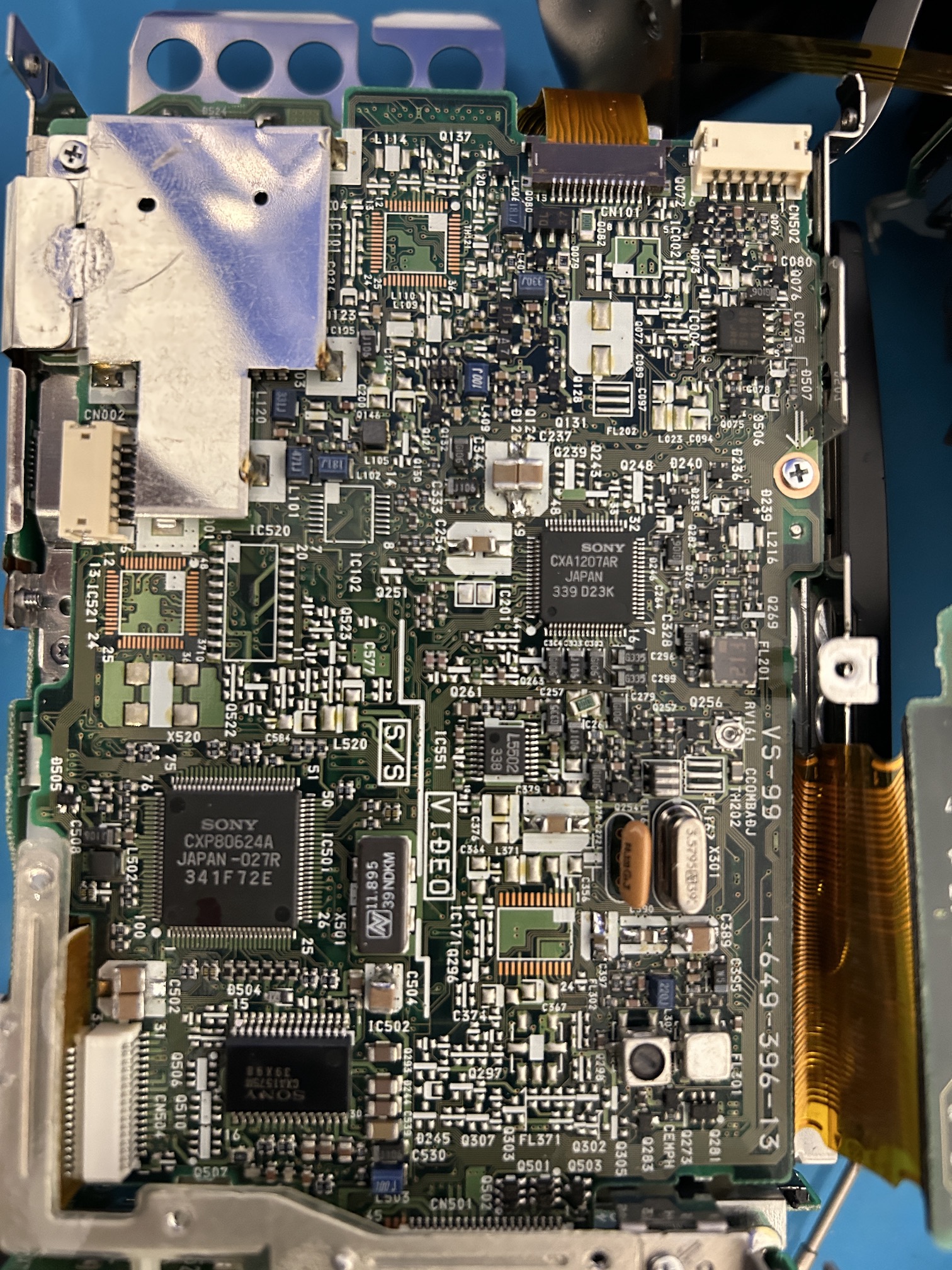
Ceramicized Boards
VC-99 (REC/PB Head Amplifier, Video, Servo System Control)
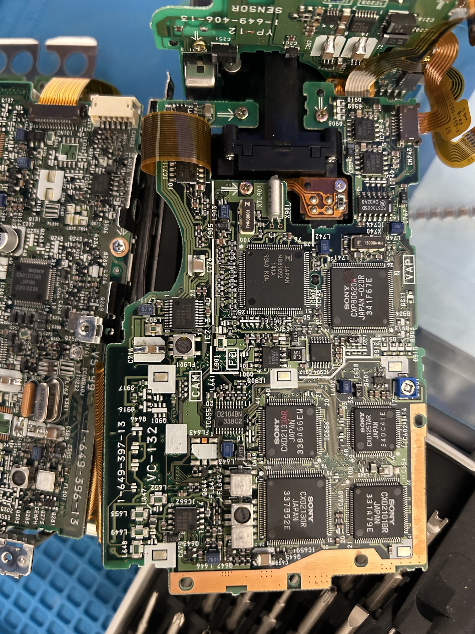
VC-132 (Camera, Lens Drive, Mode Control, Lens Control)
AU-149 (Audio/Video Board)
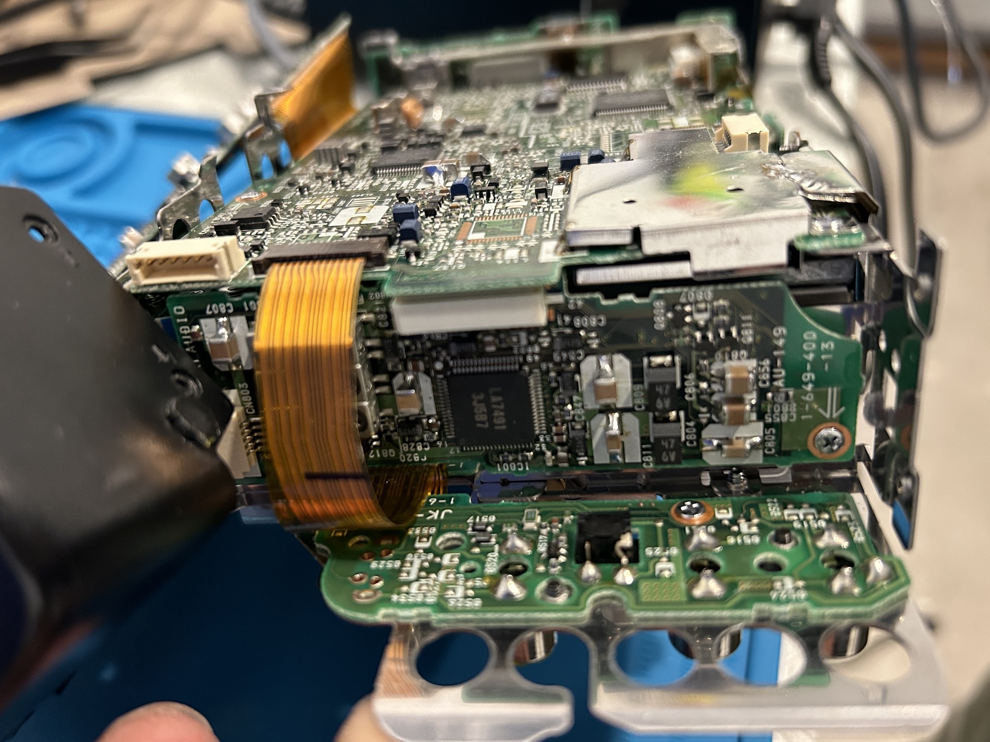
MA-169 (Mic Amplifier)
You can see the SMD capacitor that is ready to leak 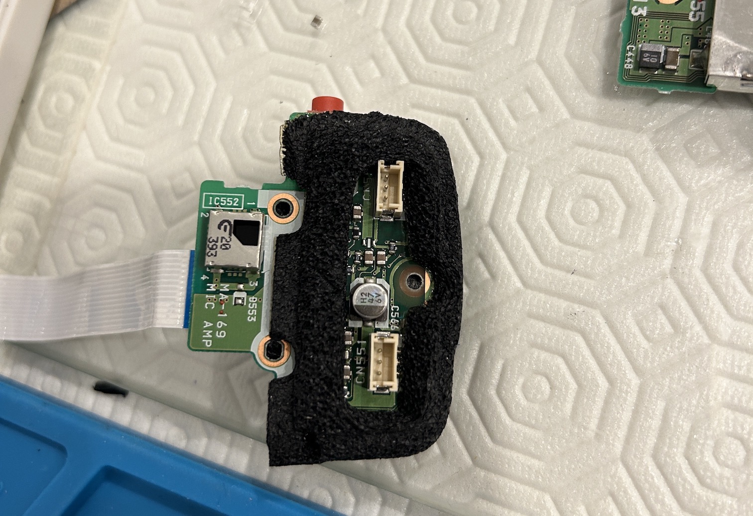
Once you cut the capacitor, you can observe the liquid that could have leaked out 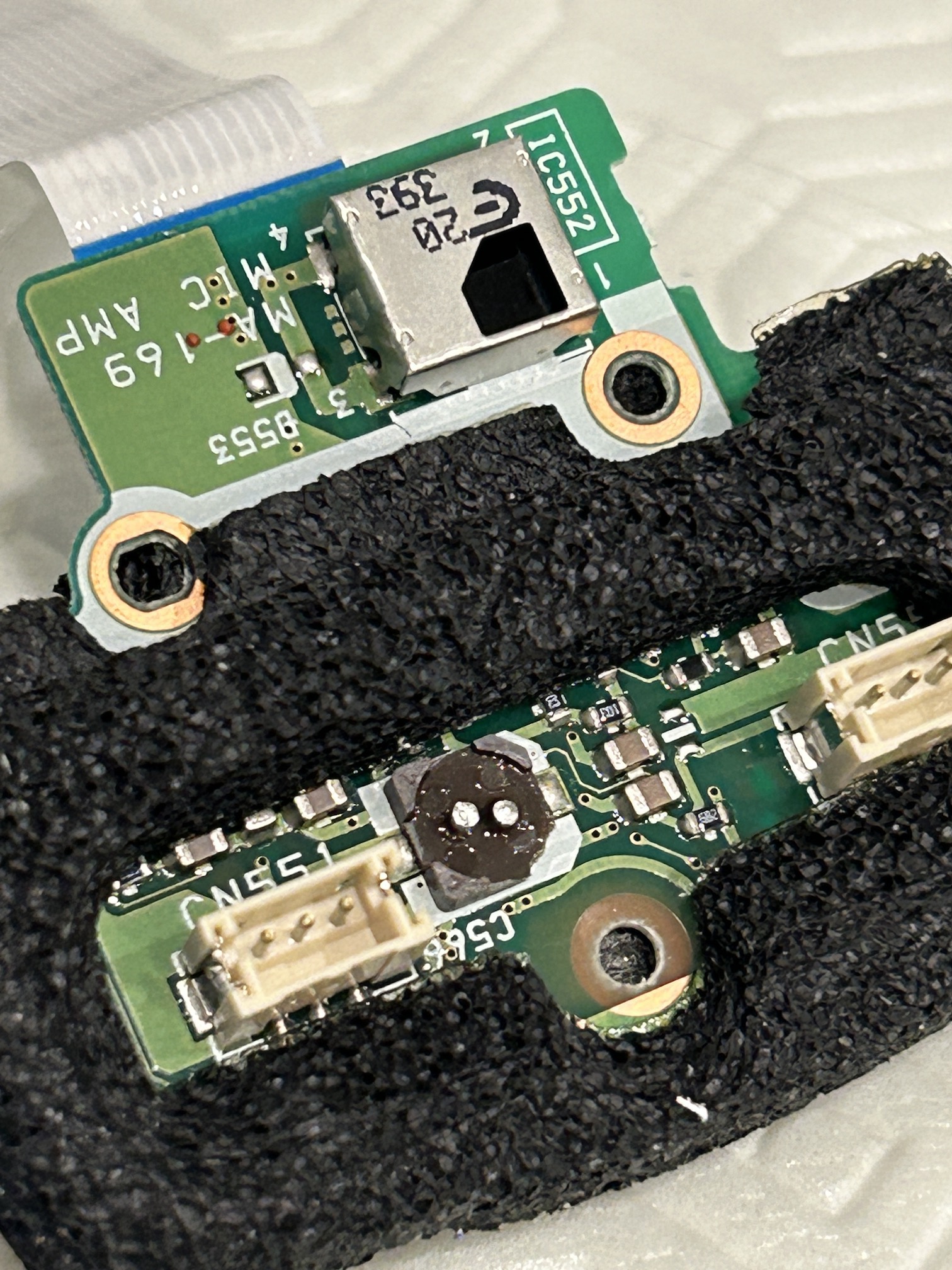
Recapping with a ceramic capacitor 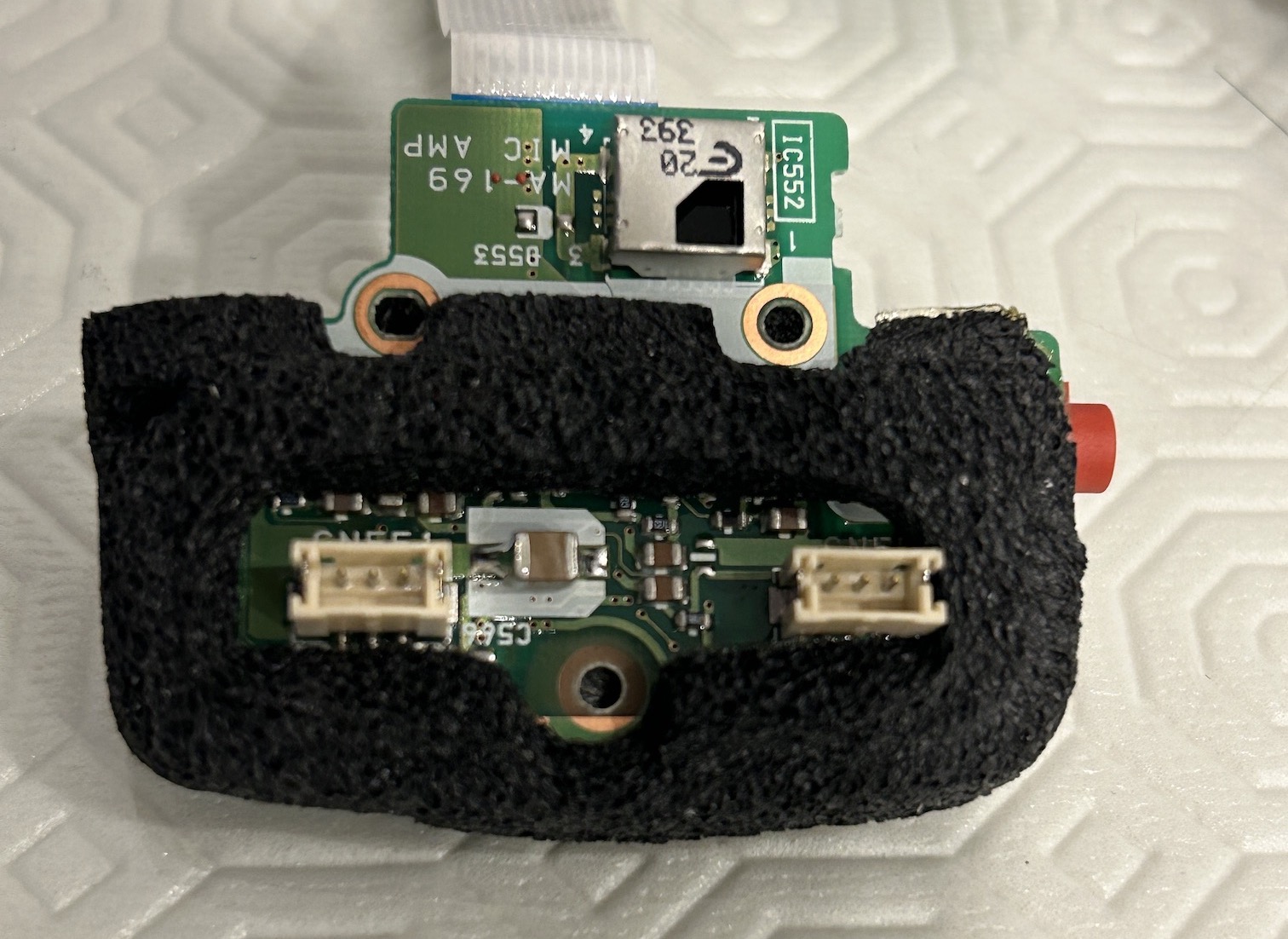
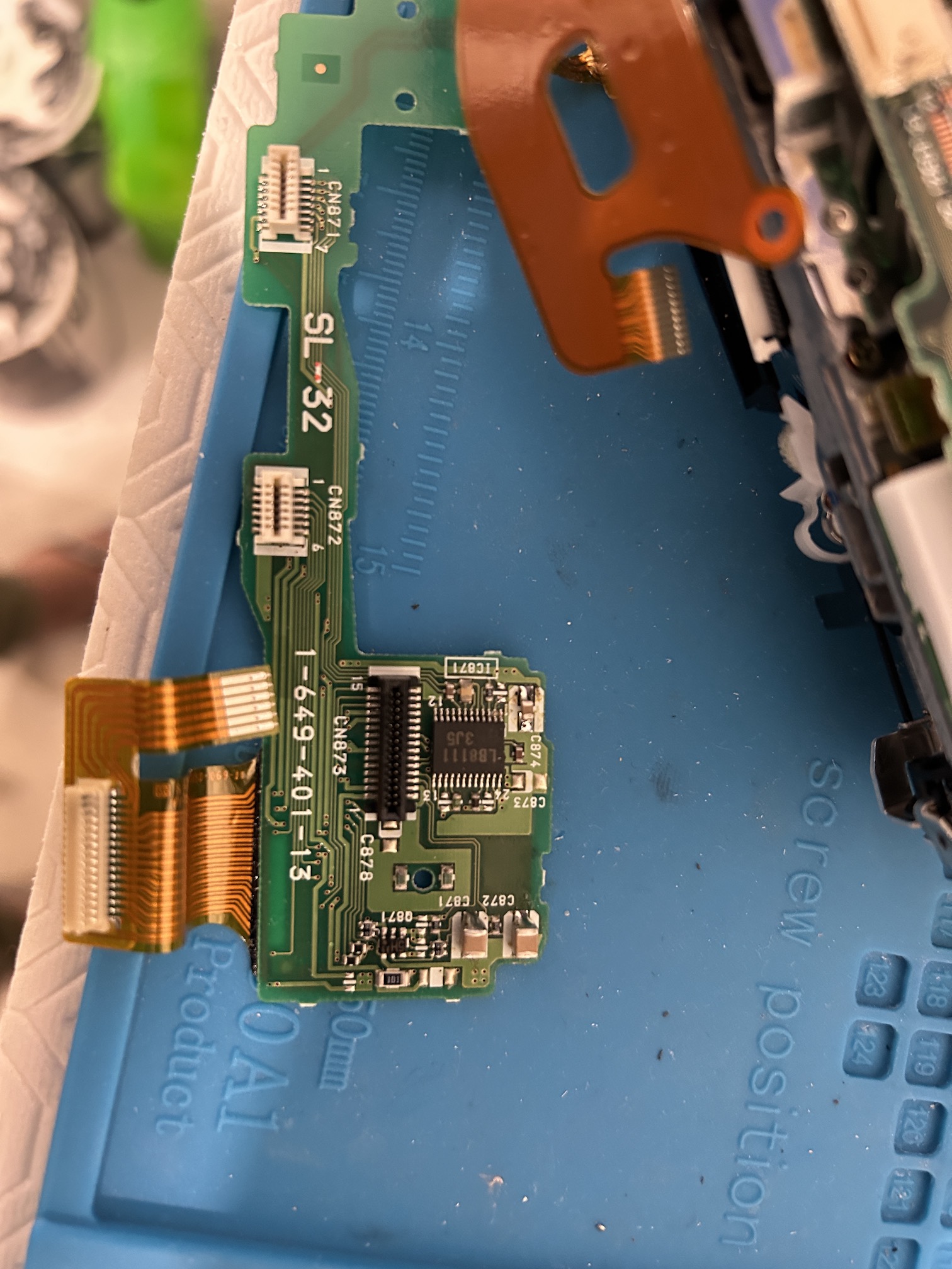
SL-32 (FG/PG Waveform Shaping)
Taking good care in removing the SL-32 board. It needs to be unplugged in several places, so take your time. Last thing you want is a ripped ribbon cable or a cracked pcb. 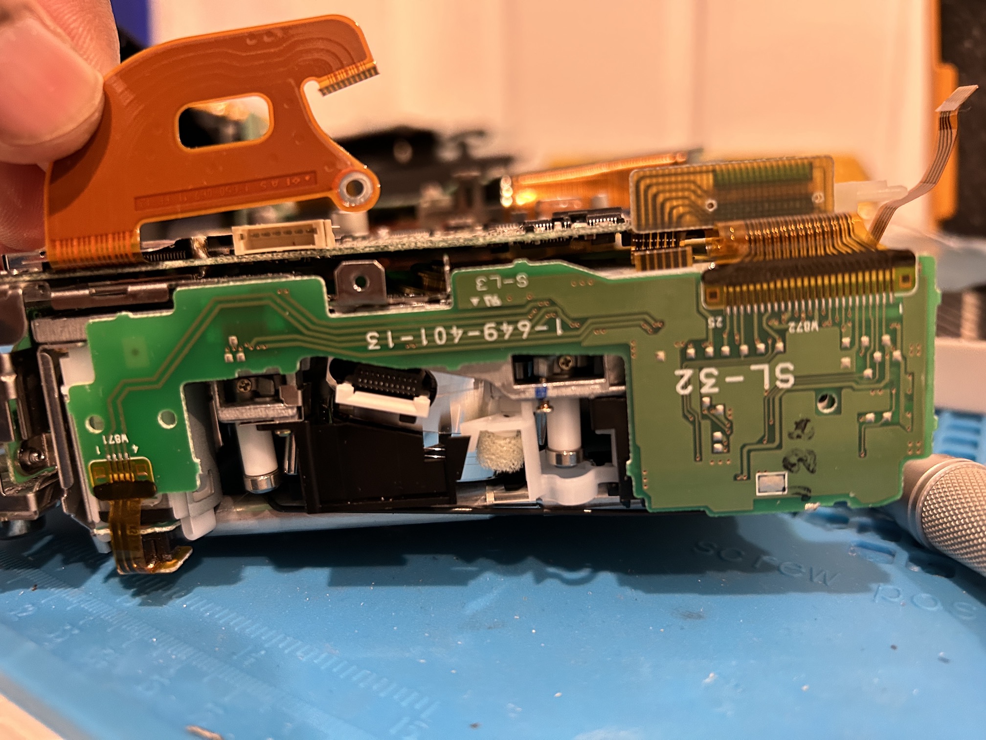
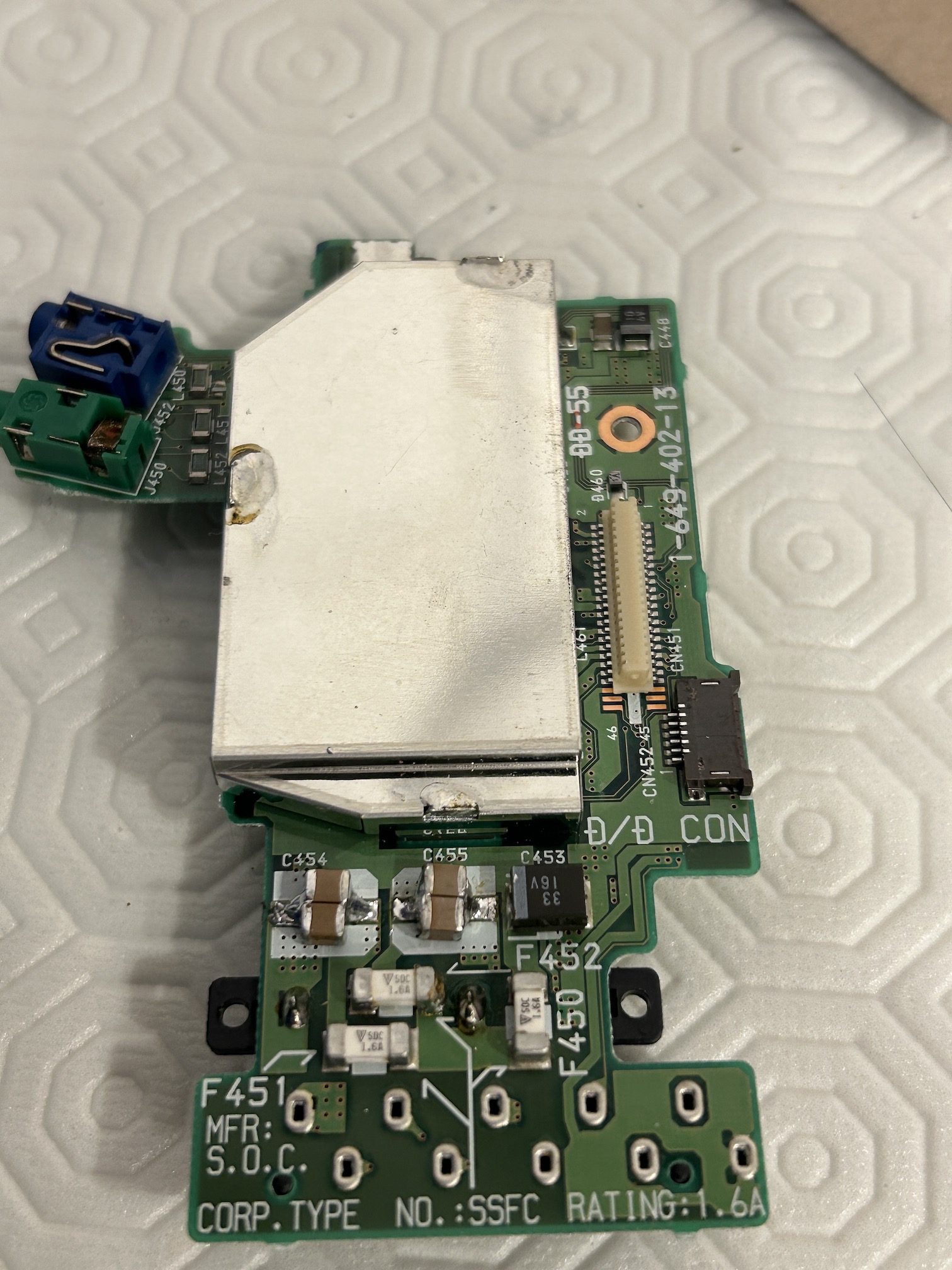
DD-55 (DC-DC Converter)
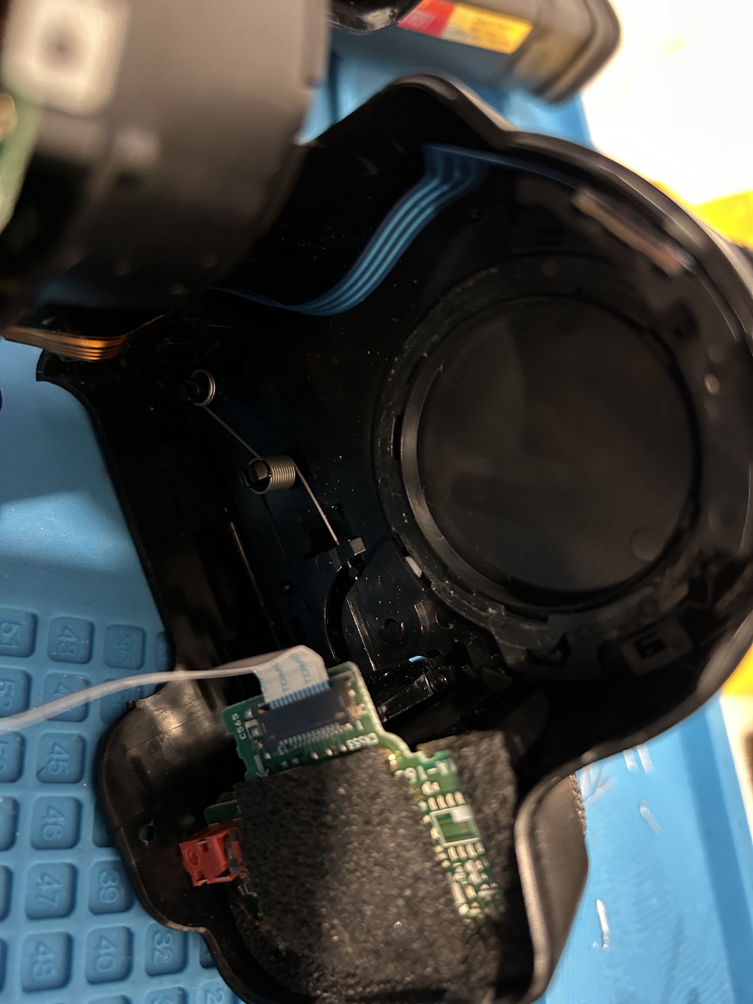
More disassembly pictures
The yellow residue seen on the below picture is not flux. It is leaked sticky liquid from the capacitor. This acidic liquid can eat through the traces overtime and damage other components. 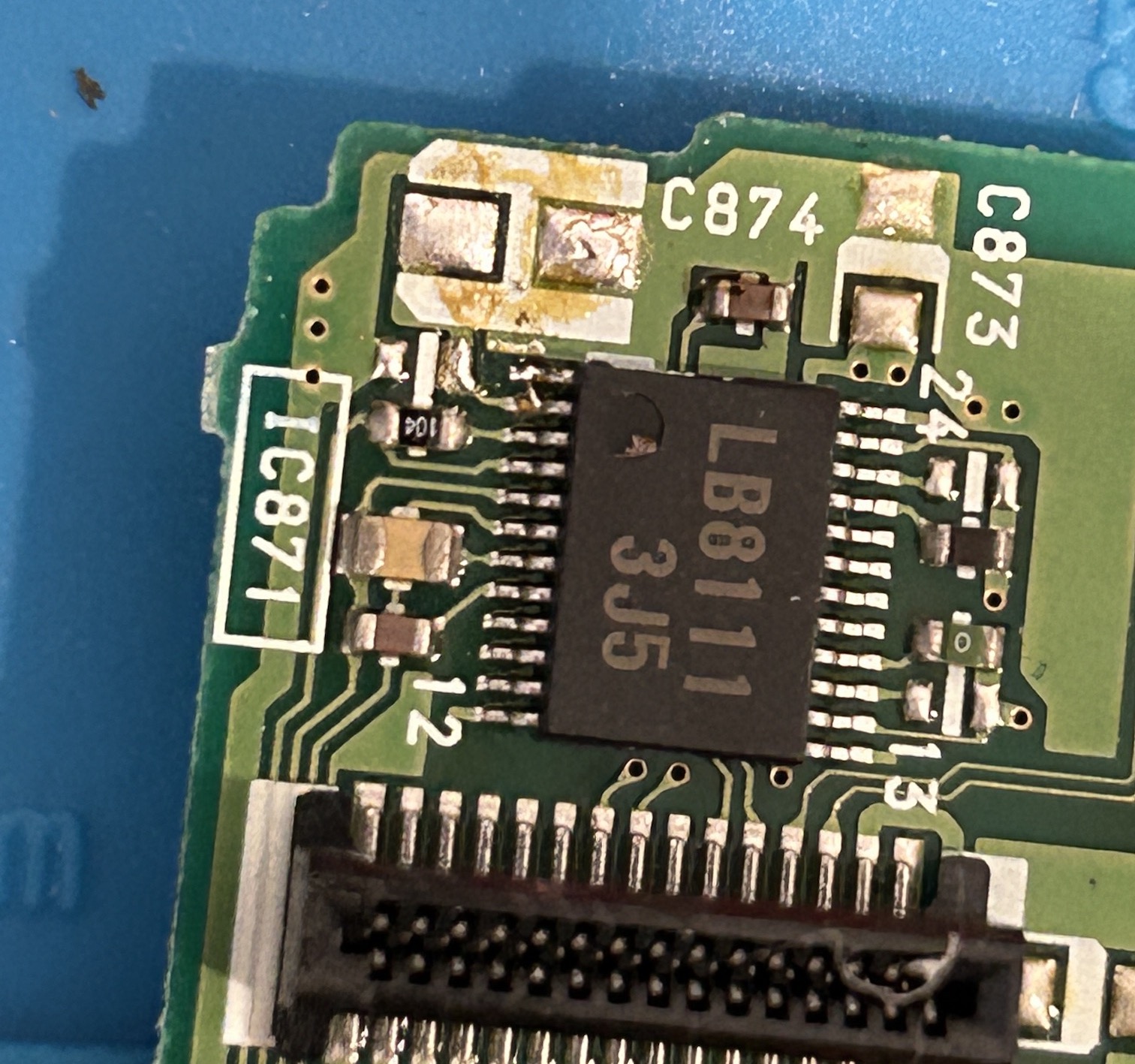
Viewfinder lens can be removed and cleaned. 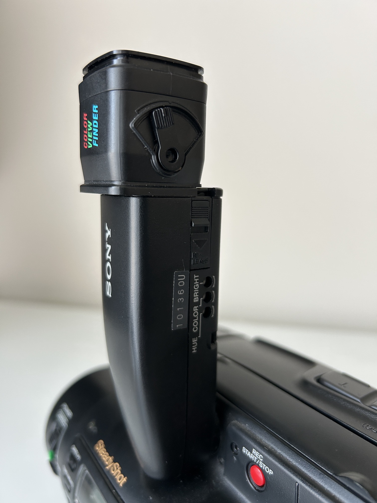
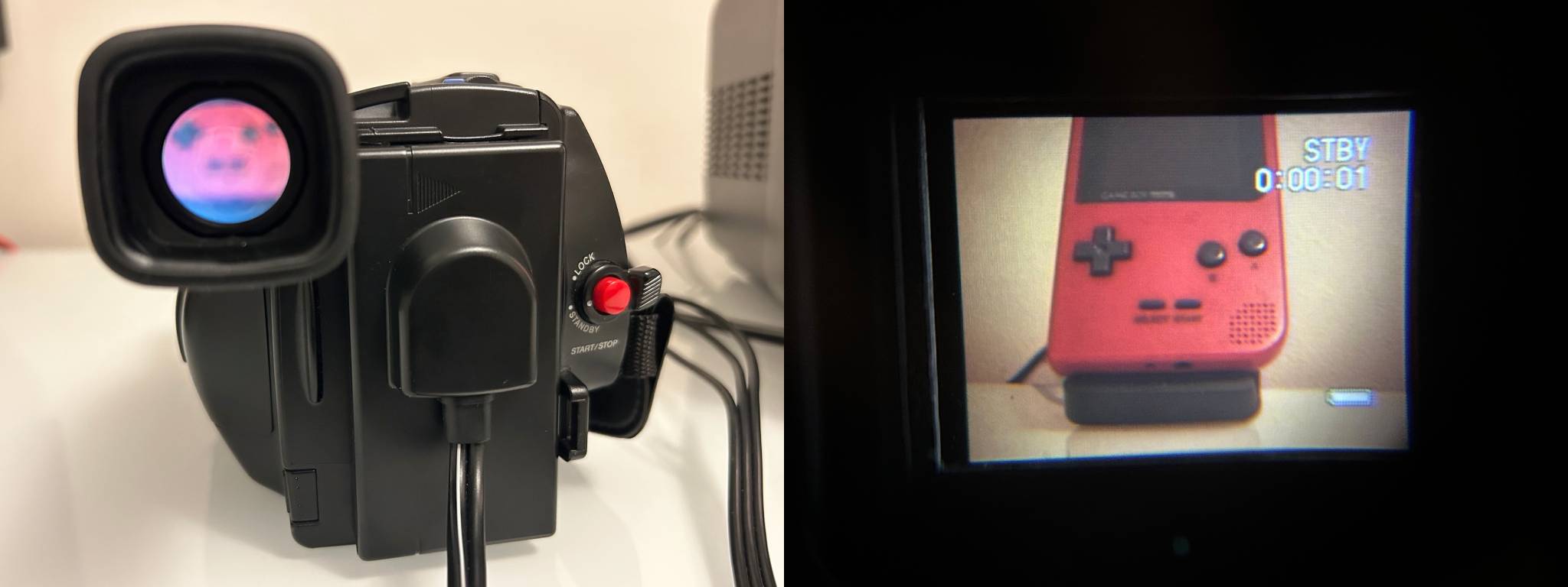
Color viewfinder
This viewfinder uses LCD technology instead of CRT. Considering its production year and size, the resolution on this viewfinder is quite decent. Below pictures were taken using an iphone.
Capacitor List
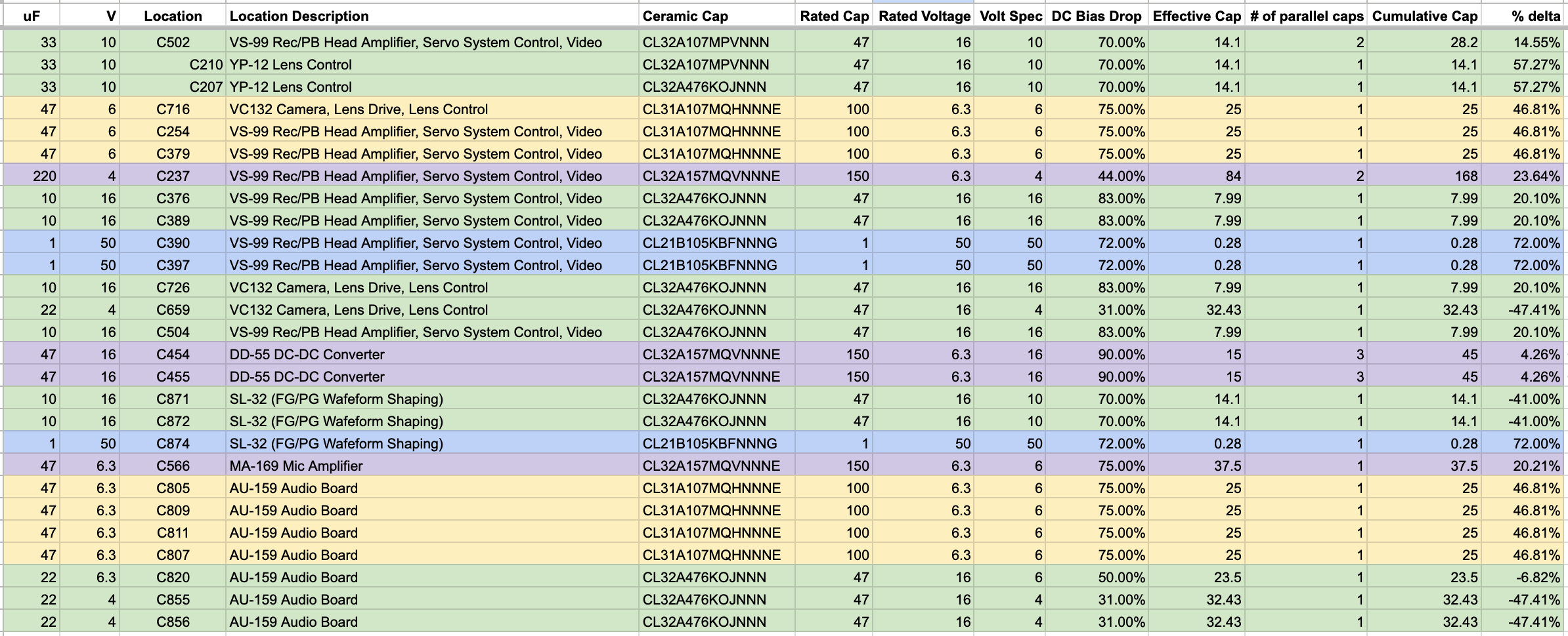
Selecting the right ceramic capacitors involves a bit of science. I'll be preparing another article that goes into detail on how to make those choices. Here's a table showing the equivalent ceramic capacitors used for reference. I will be writing up another article on how to do that in detail. Below is a table of the equivalent ceramic capacitors used.
In certain ocassions I would've used a higer ceramic capacitance than the original electrlytic capacitor replaced. However, I ensure they fall within the tolerance level when the correct DC bias is applied. For example, I utilized two 150uF, 6.3V ceramic capacitors to replace a 220uF, 4V capacitor. When you apply the DC bias to the combined 300uF, the effective capacitance drops to less than 170uF. While 170uF is much lower than 220uF, I consider this to be within the tolerance level and suitable for the specific application. Ceramics also have a lower ESR (Equivalent Series Resistance).
4 different types of ceramic capacitors were used.
- Samsung CL32A107MPVNNN (14)
- Samsung CL31A107MQHNNNE (7)
- Samsung CL32A157MQVNNNE (9)
- Samsung CL21B105KBFNNNG (3)
