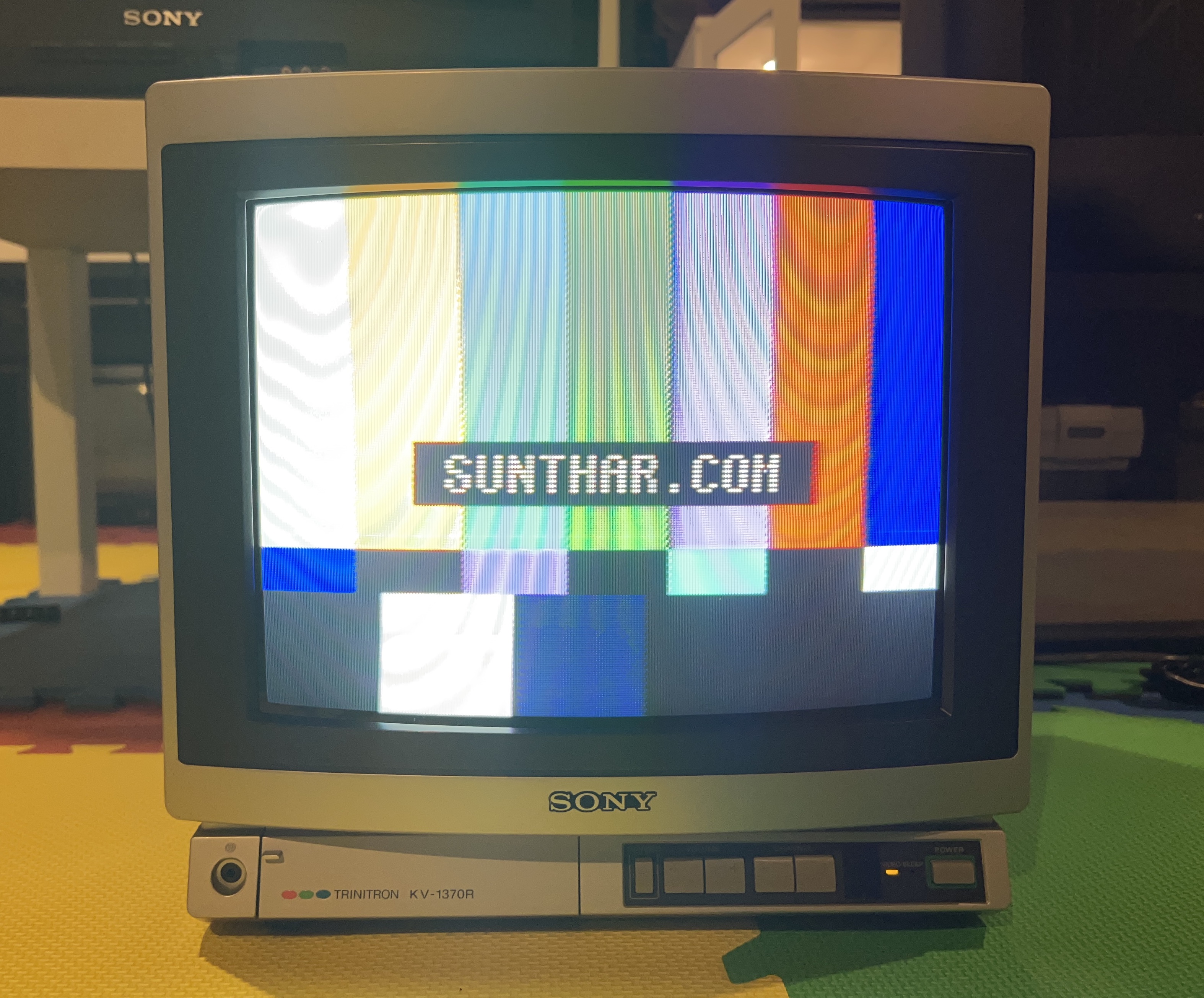
Sony KV-1370R (Grey)
Sony KV-1370R from 80s
You’ve acquired a beautiful 1365R or 1370R, only to find the audio isn’t working. Luckily, the fix isn’t too complicated if you have the schematics and the service bulletin Sony issued in August 1987. However, as always, the devil is in the details.
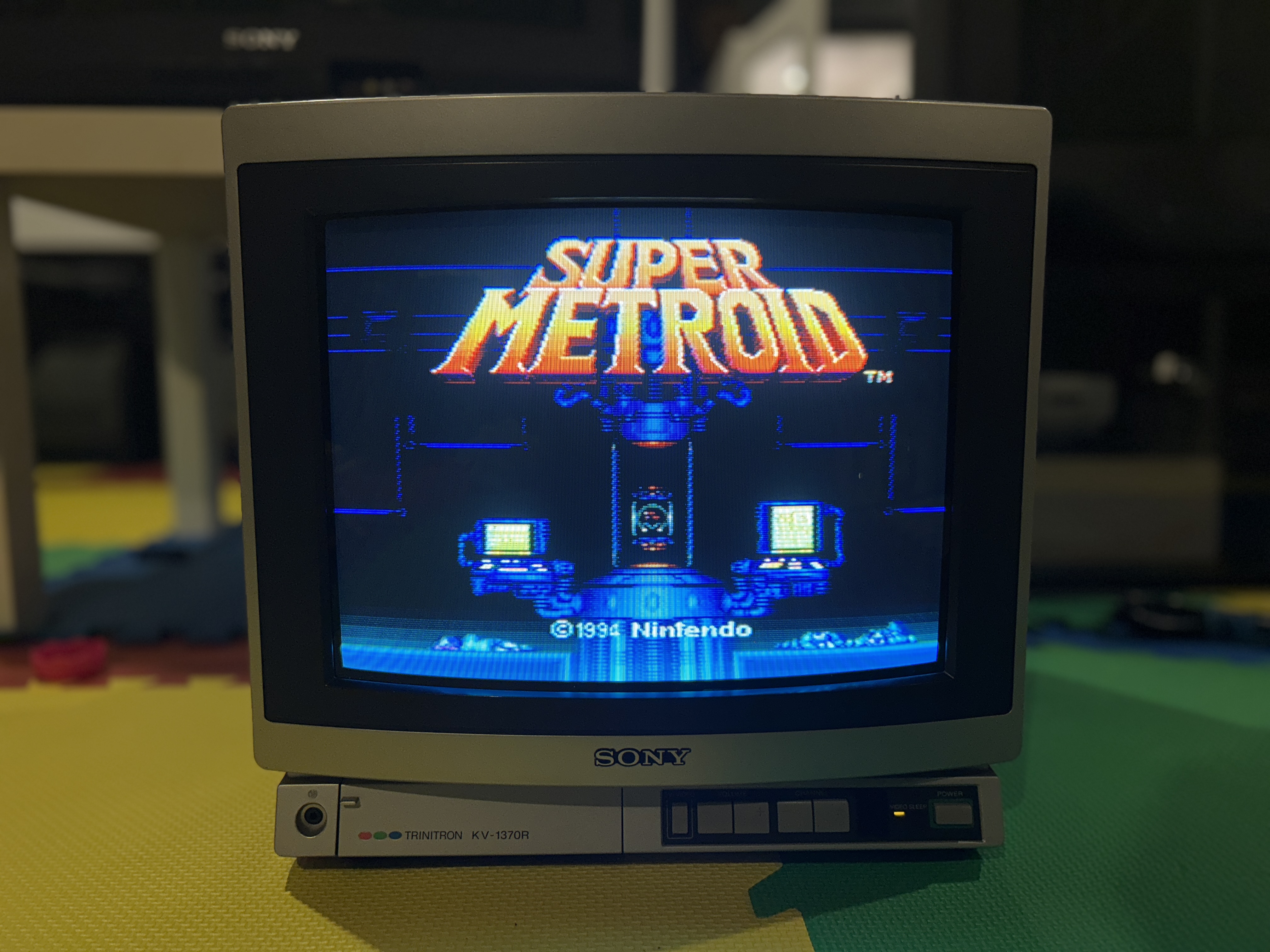
When I first tackled this problem, I referenced the schematics and purchased transistors I believed were suitable replacements. What I learned was an important lesson: the audio amplifier circuitry in these old sets, which uses both NPN and PNP transistors, requires matched transistors. This means it’s not enough to just get transistors with the correct part #; the NPN and PNP transistors must also have matching hFE (DC current gain) values for the audio amp to function properly.
As you can see in the video, I eventually got it working after a few attempts. I’m happy to have restored the audio on this beautiful TV. I’ve always loved the aesthetics of these sets. I was driving back from Quebec City this summer and glad I made the decision to pick this up on my way back for $50 Canadian.
Keep in mind, not all 1370Rs are affected by this issue. There was a revision made to 1370R later in the 80s. Later revision chassis had an audio fault, which is something we will delve into this article. This audio issue also affects 1365R CRTs as well. So, if your audio is functioning, there’s no need to replace the components. Only consider this fix if your audio isn’t working.
Warning
It's important to note that the KV-1370R operates with a hot chassis setup, meaning the ground isn't isolated on the low voltage side. Consequently, modifying it for RGB input is not straightforward.
Taking this set apart 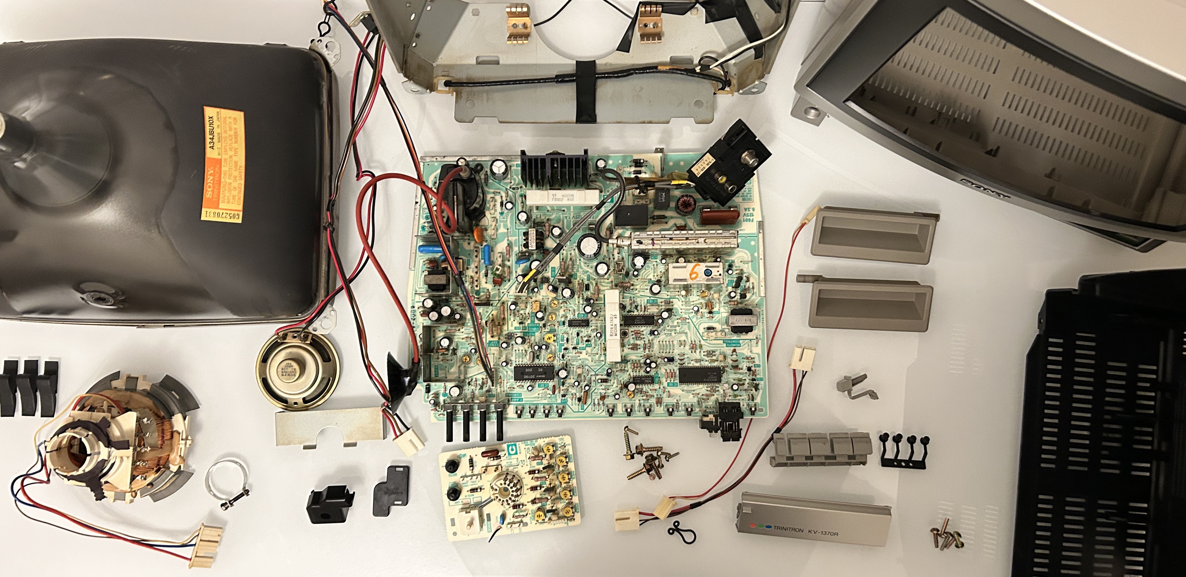
Sony KV-1370R (grey) specs
- Manufactured: Made in Japan
- Tube: A34JBU10X, Made in Japan
- 60 Hz AC: 120V 97W
Back Label 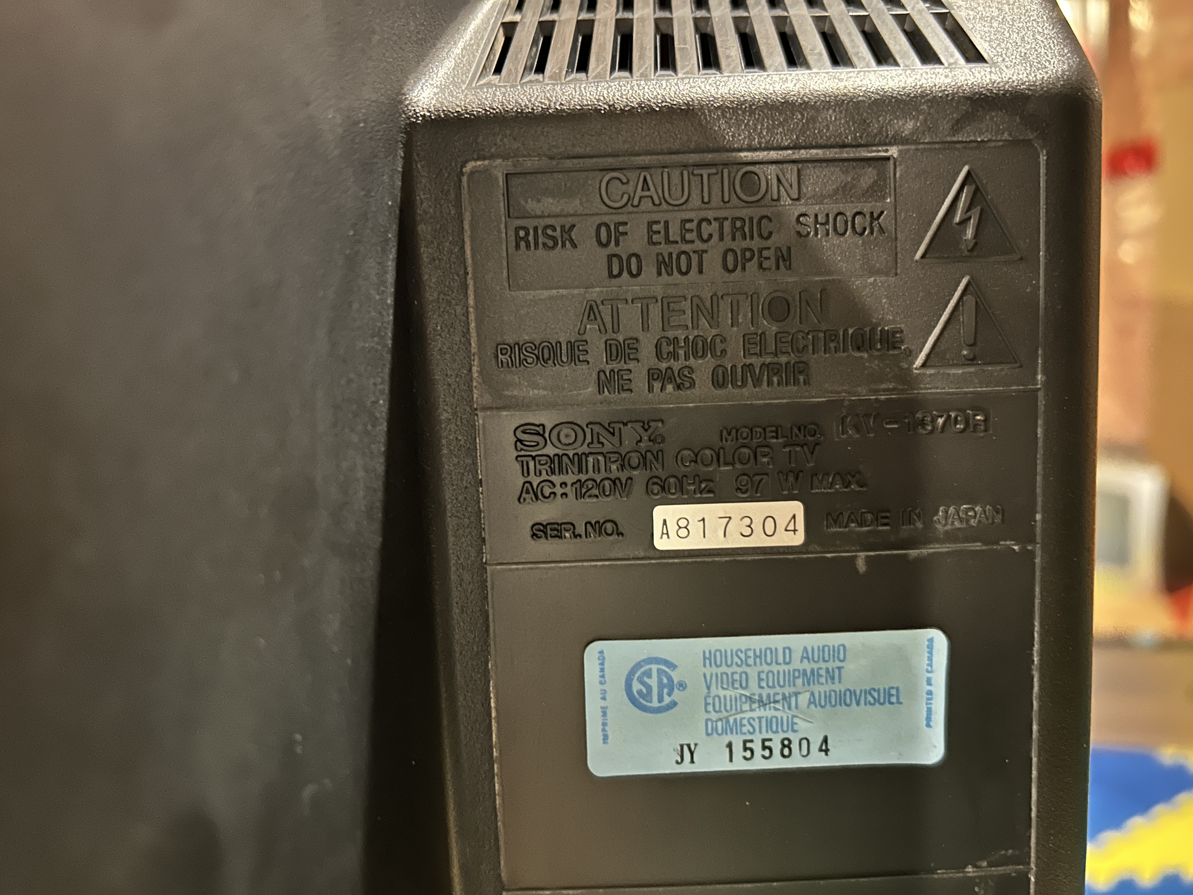
Tube 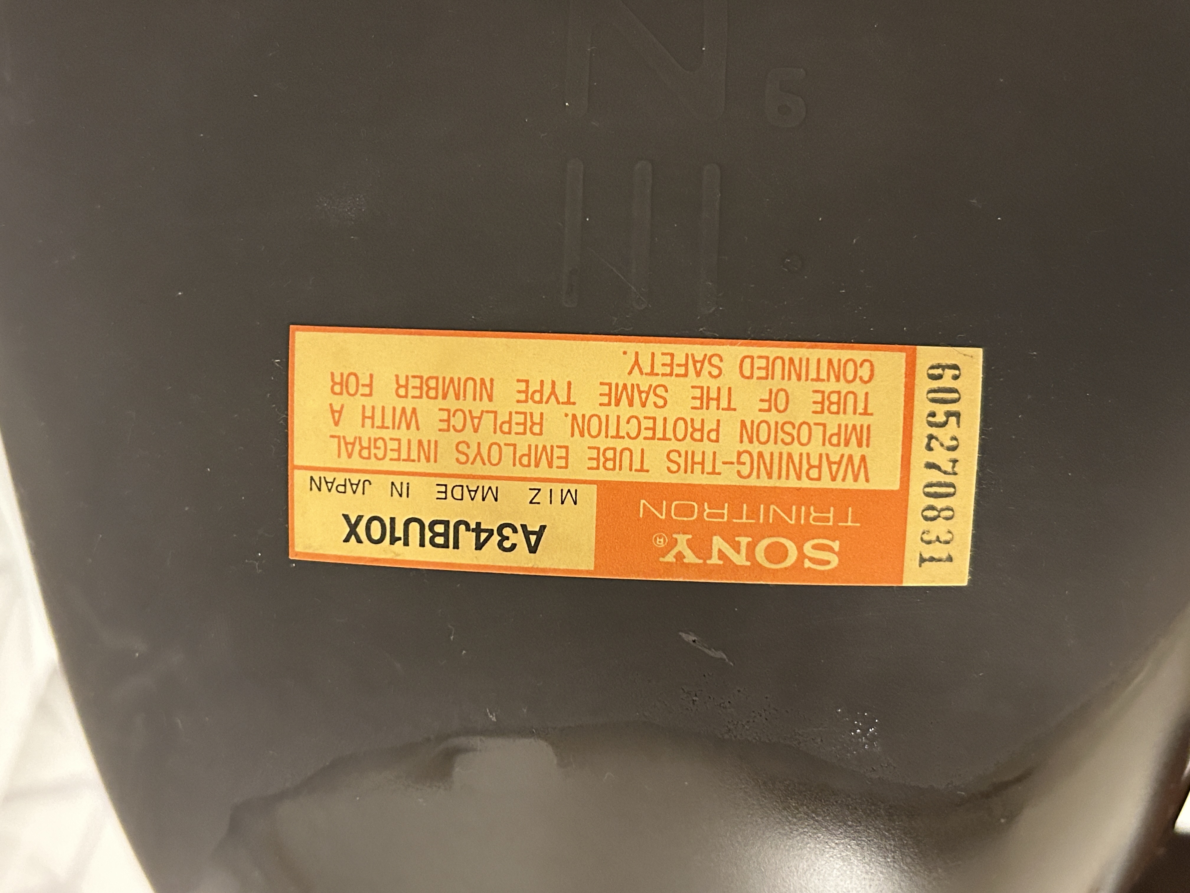
Schematics 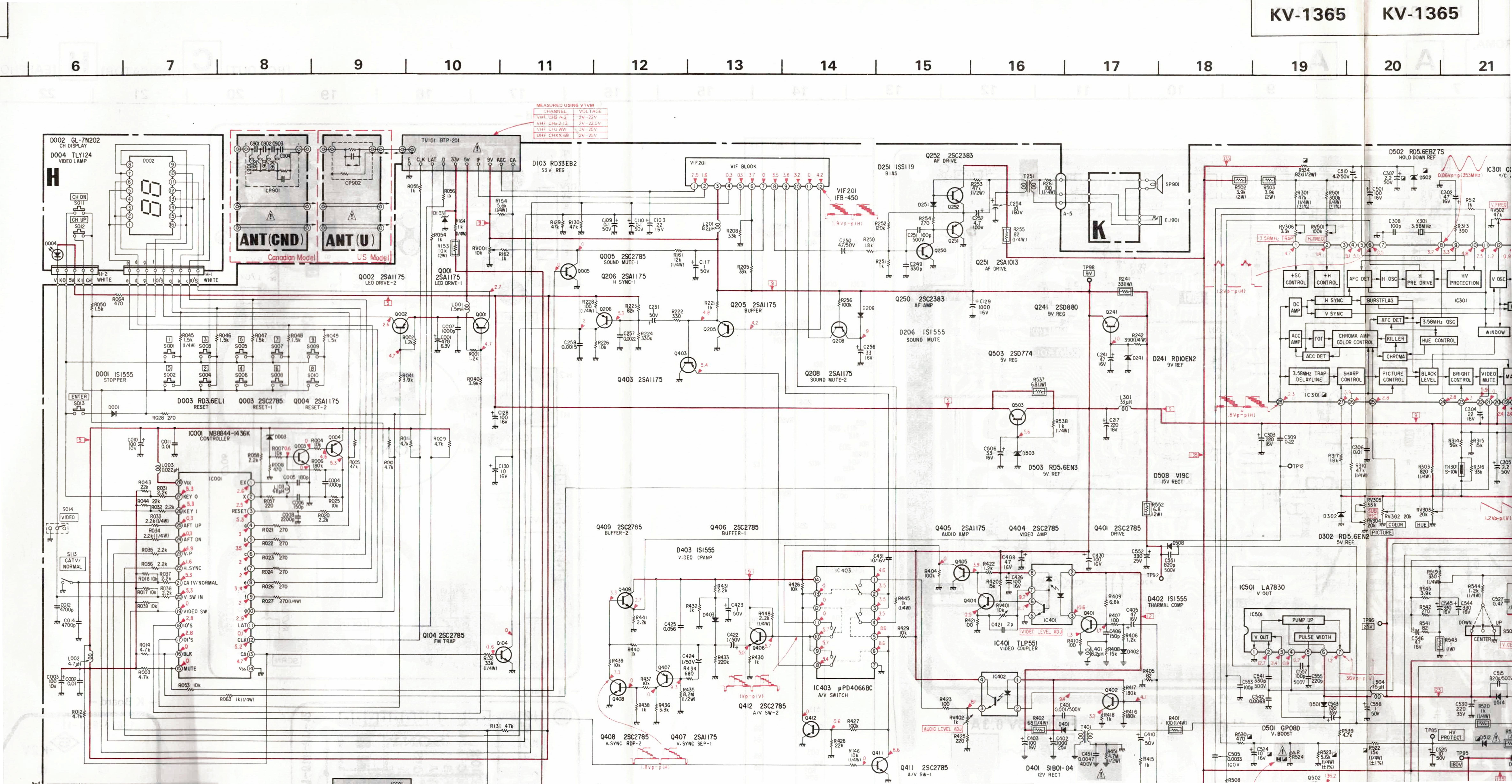
Area of Focus 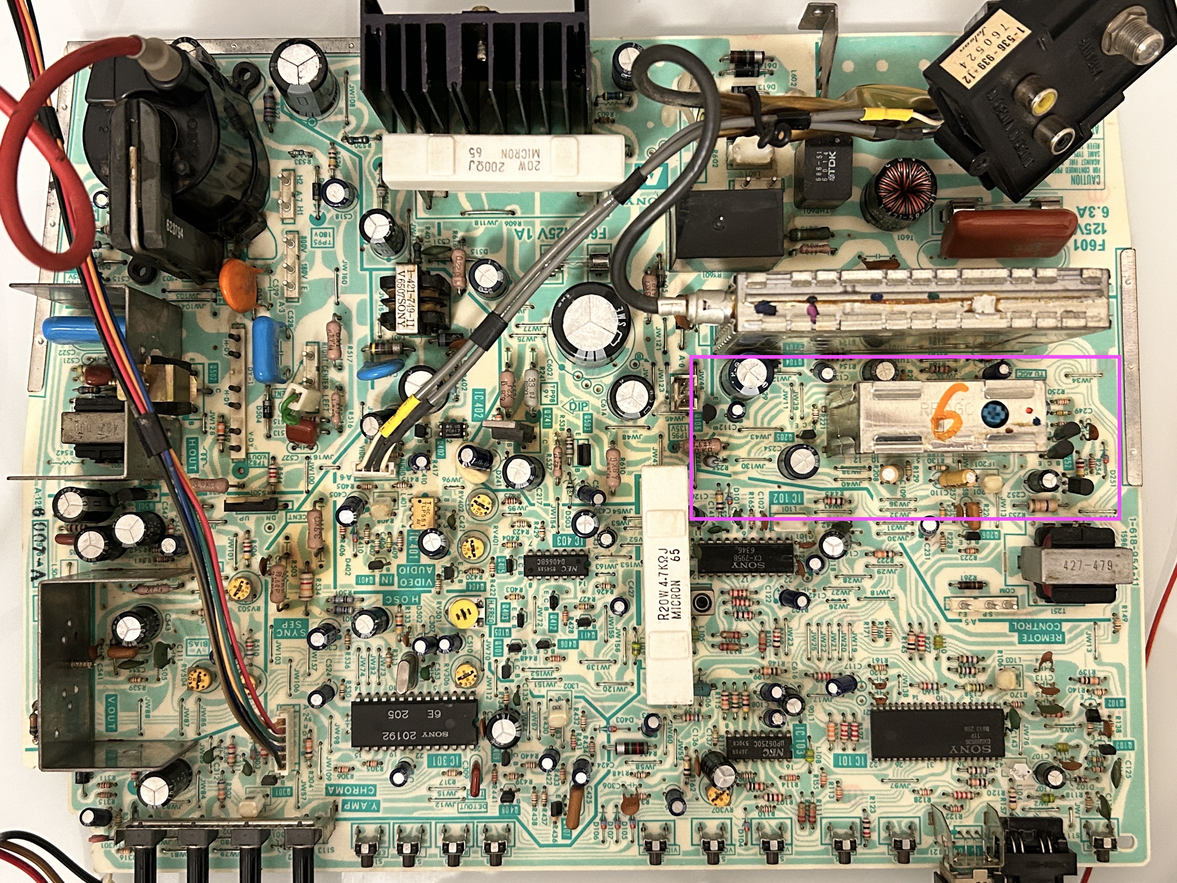
Components that must be changed are maked in yellow. Optional changes are marked in green. When addressing this issue, it's important to replace all the related components. The burnt resistor is what caused the transistors to fail in the first place. 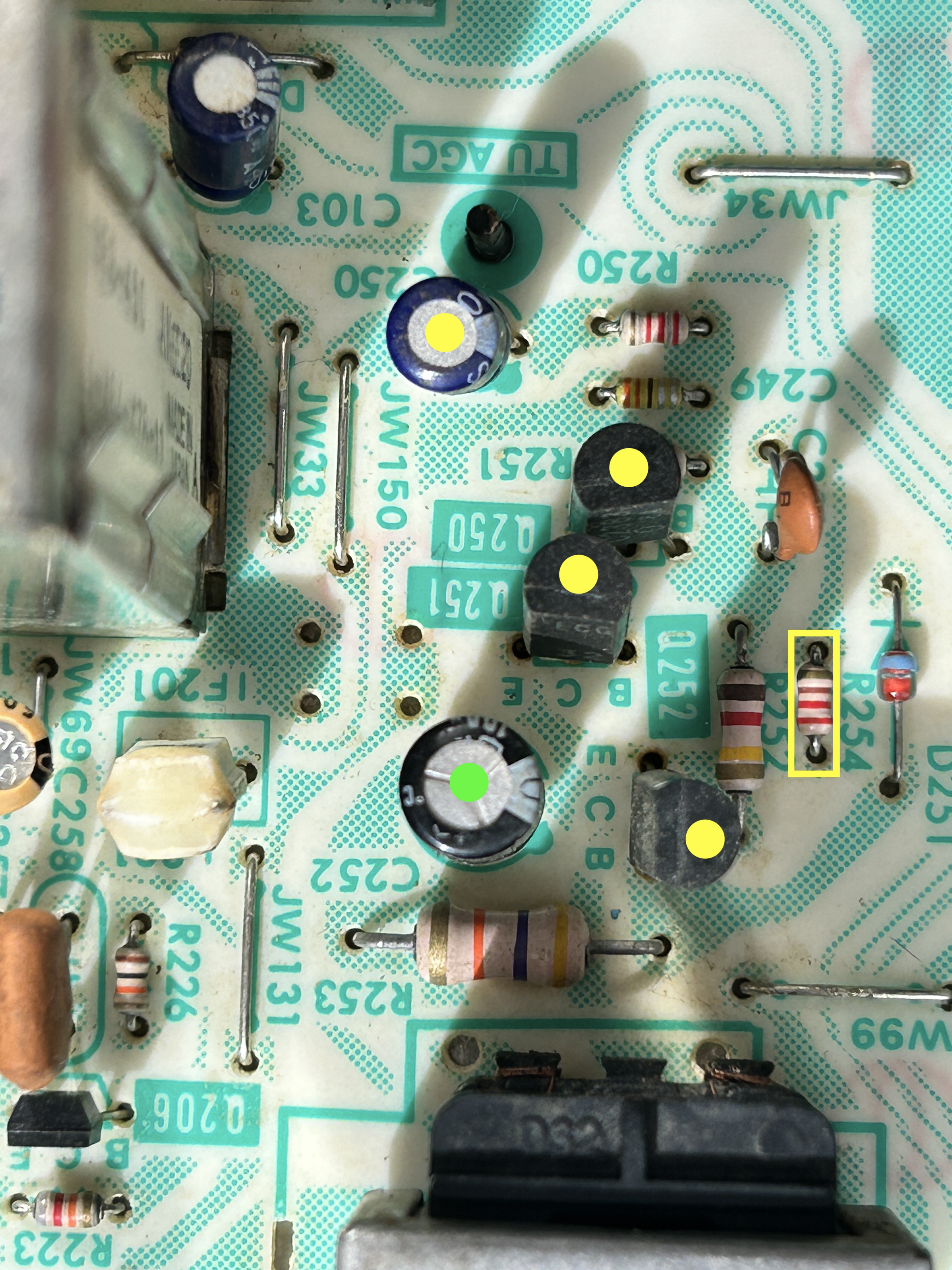
| Component | Original Specification | Replacement Specification | Notes |
|---|---|---|---|
| Q252, Q250 | 2SA1013 | KSA1013Y | Failed transistors |
| Q251 | 2SC2383 | KSC2383Y | Failed transistor |
| R255 | 1/6W, 82 ohms carbon | 1/4W, 82 ohms metal film | This resistor will be burnt/open |
| R254 | 270 ohm carbon | Short using a jumper | |
| C250 | 4.7uF, 50V | 3.3uF, 50V film capacitor | |
| C254 | 10uF, 160V electrolytic | 10uF, 160V polymer | Optional replacement |
| C252 | 4.7uF, 100V electrolytic | 4.7uF, 100V polymer | Optional replacement |
After replacing the components 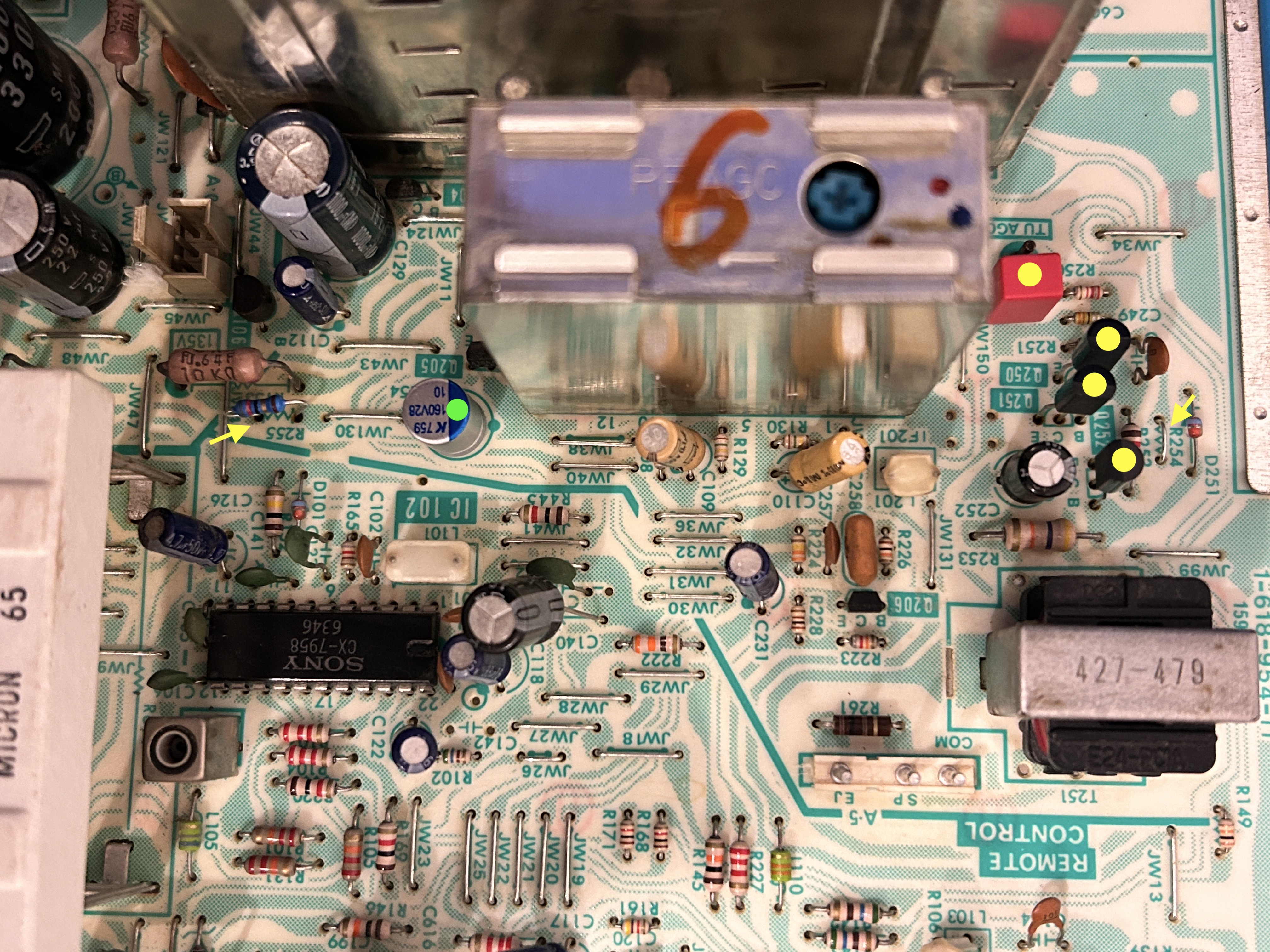
I opted to replace the audio capacitors with film and aluminum polymer capacitors to enhance reliability. This is optional. Only replace capacitors if they are out of spec.
Components replaced 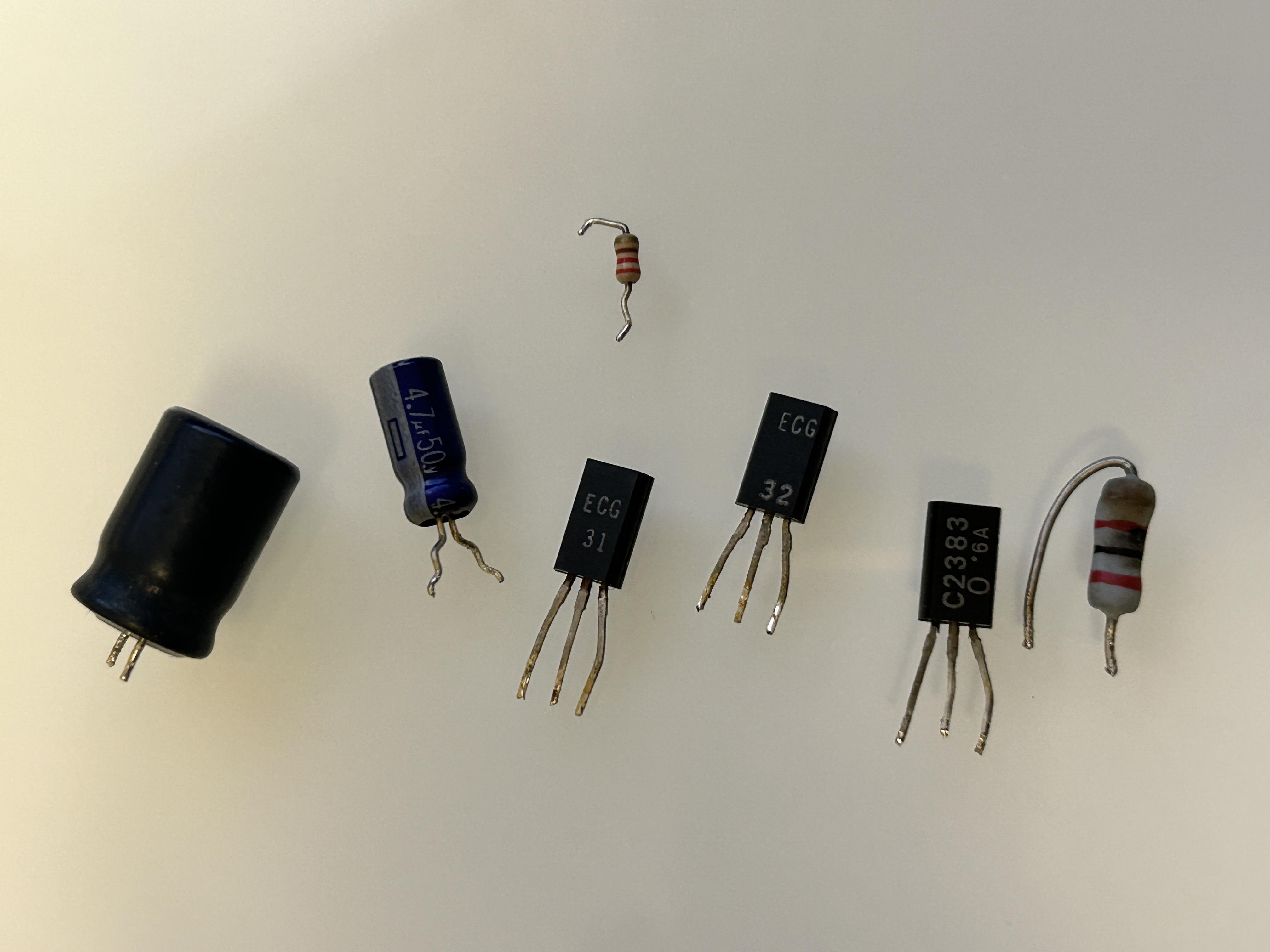
Replacement kit 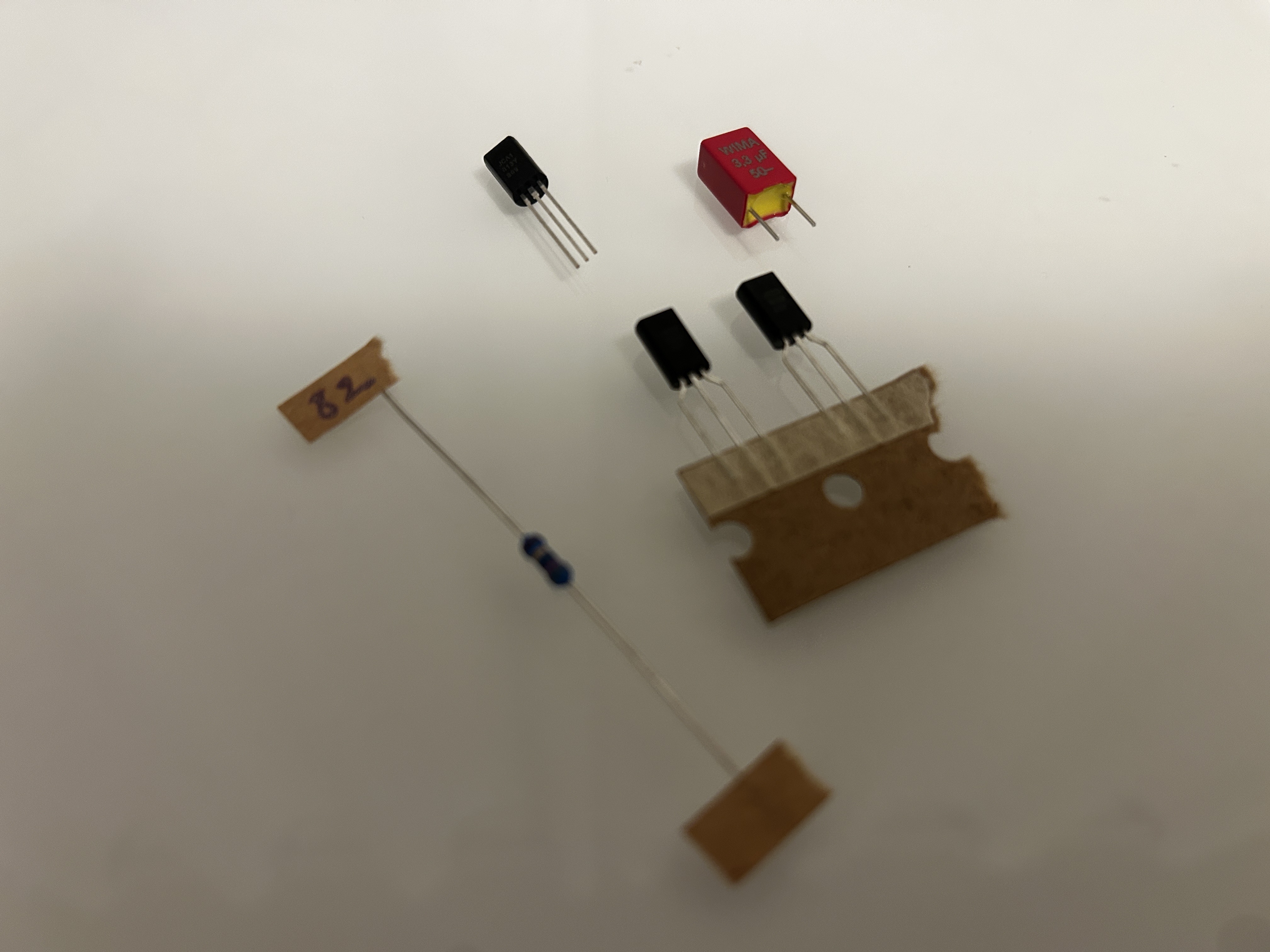
If you are interested in purchasing this kit checkout my store.
Video showing the difference between using matched vs unmatched transistors in the audio amp. The difference in audio quality between matched and unmatched transistors is significant. When the hFE values aren’t matched, you can hear the audio distort and rattle. This issue is common with older audio amplifier circuitry, whereas modern audio amps are designed to avoid this flaw.
Other pictures
Tube mounted 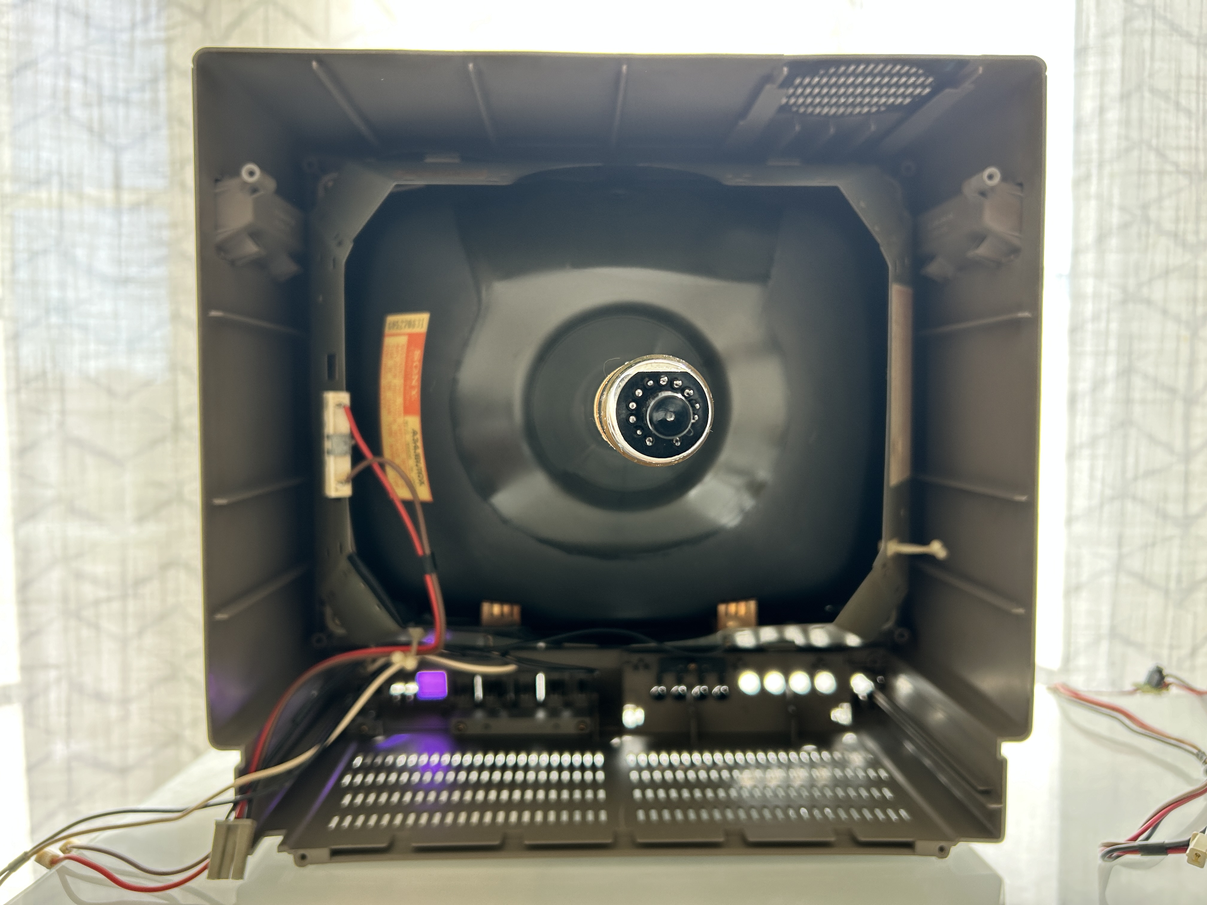
Neck board 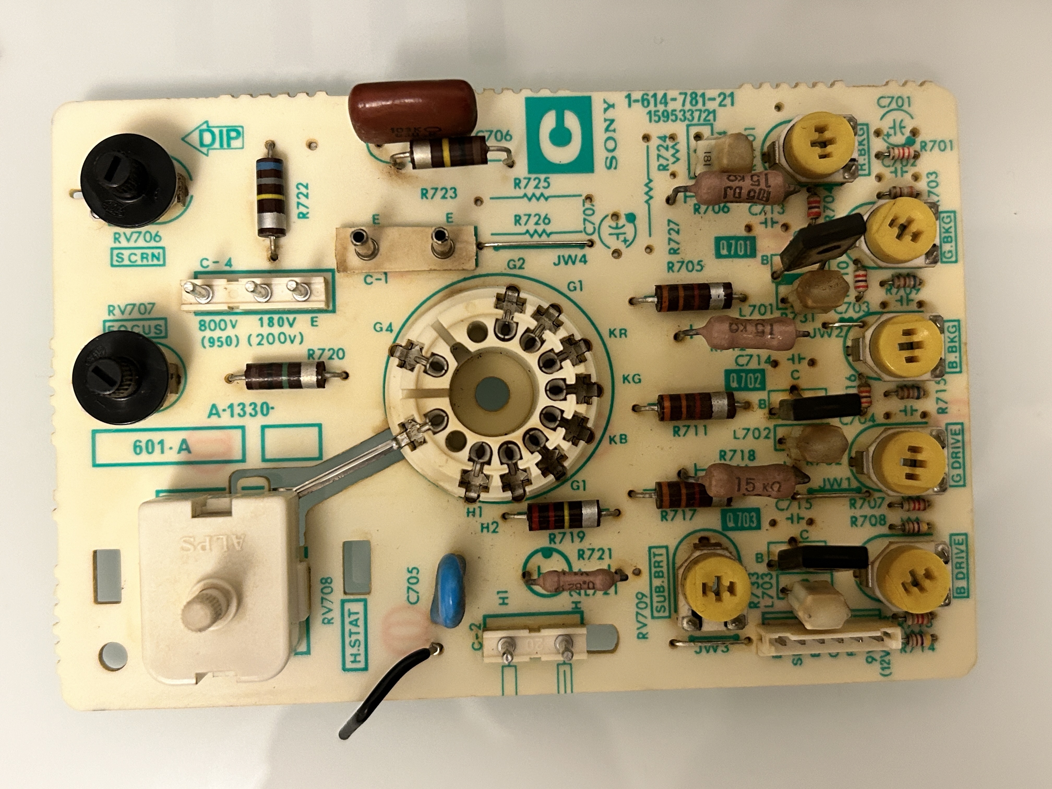
Yoke 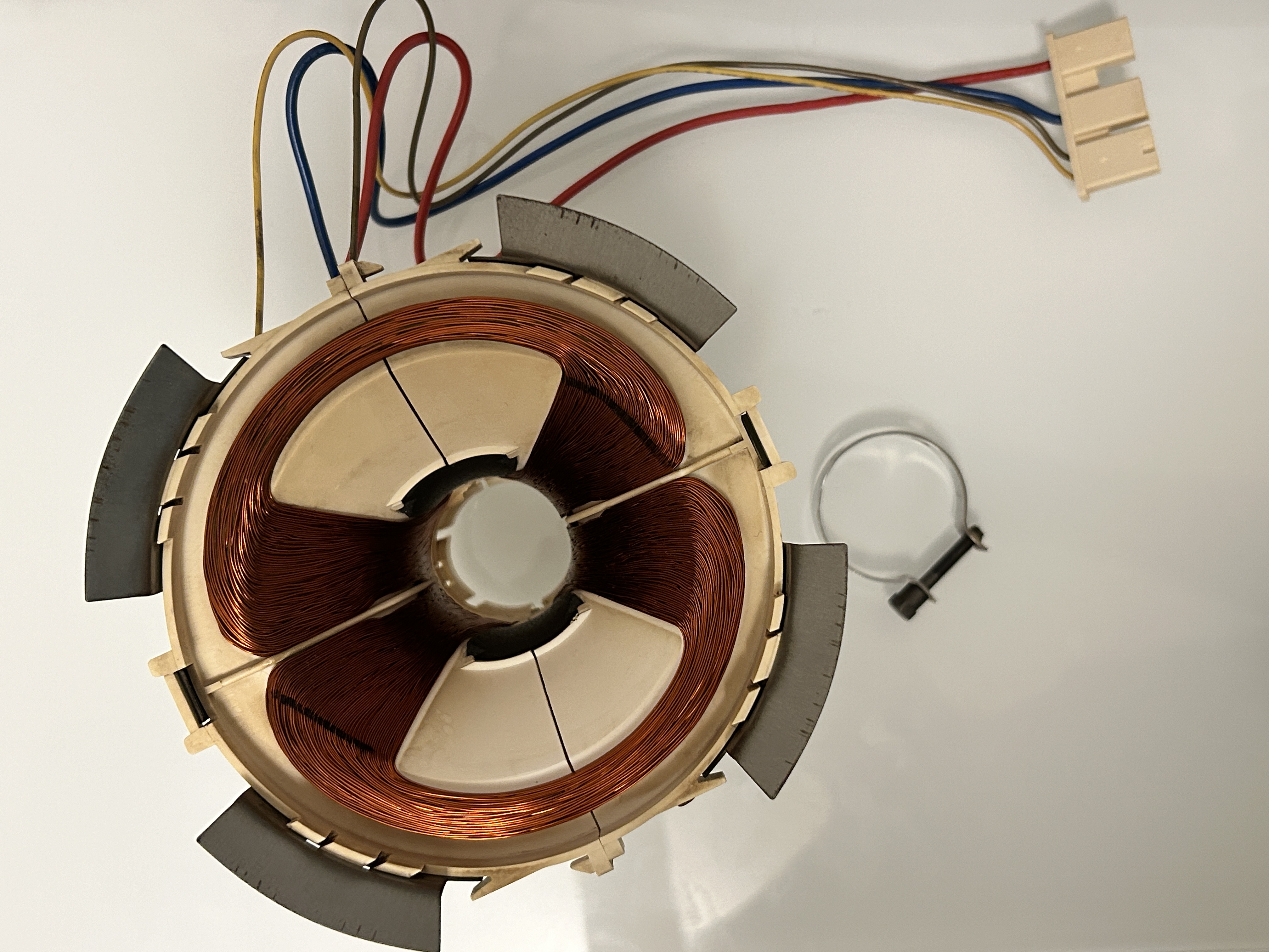
Set
Side view 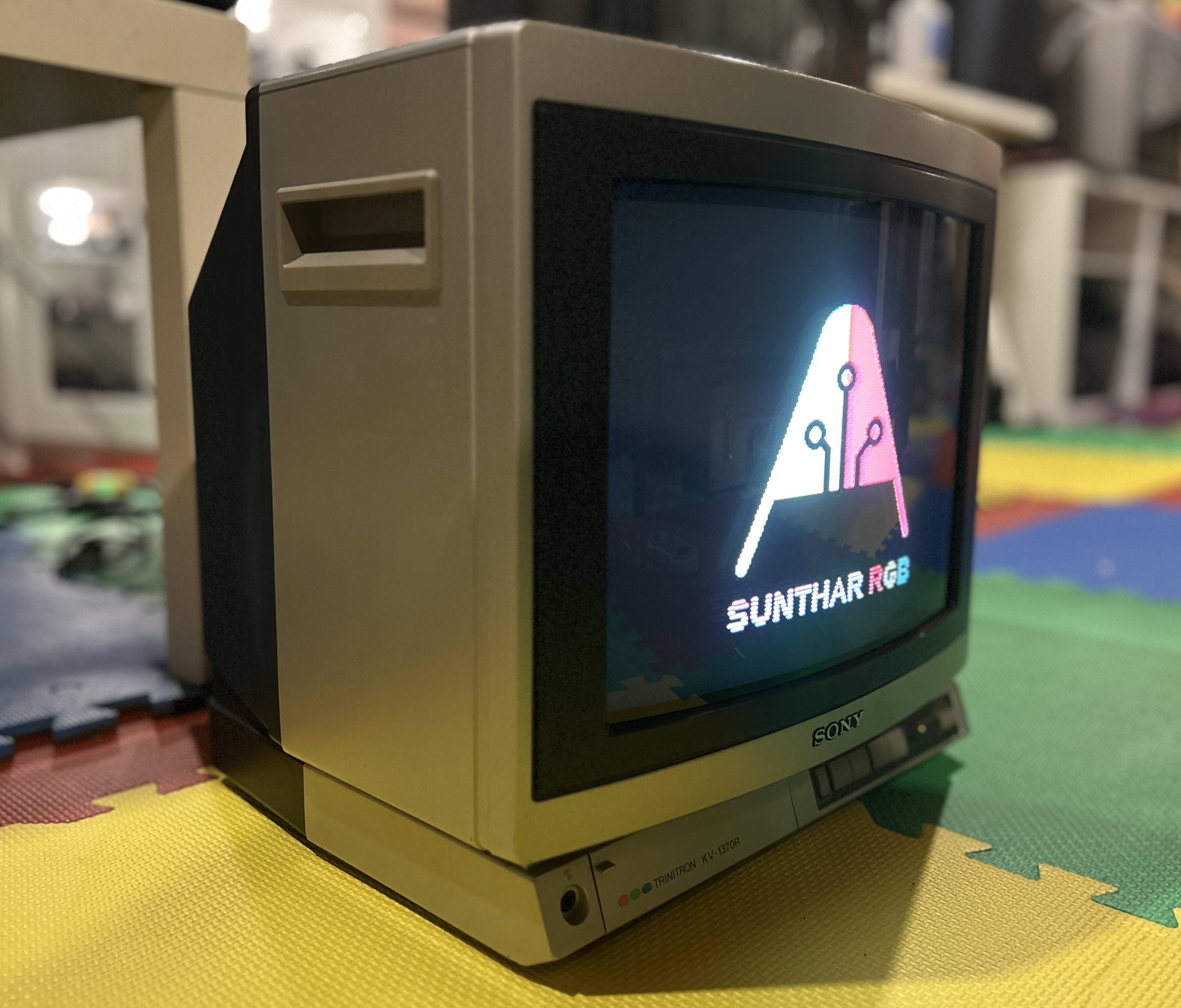
Top view 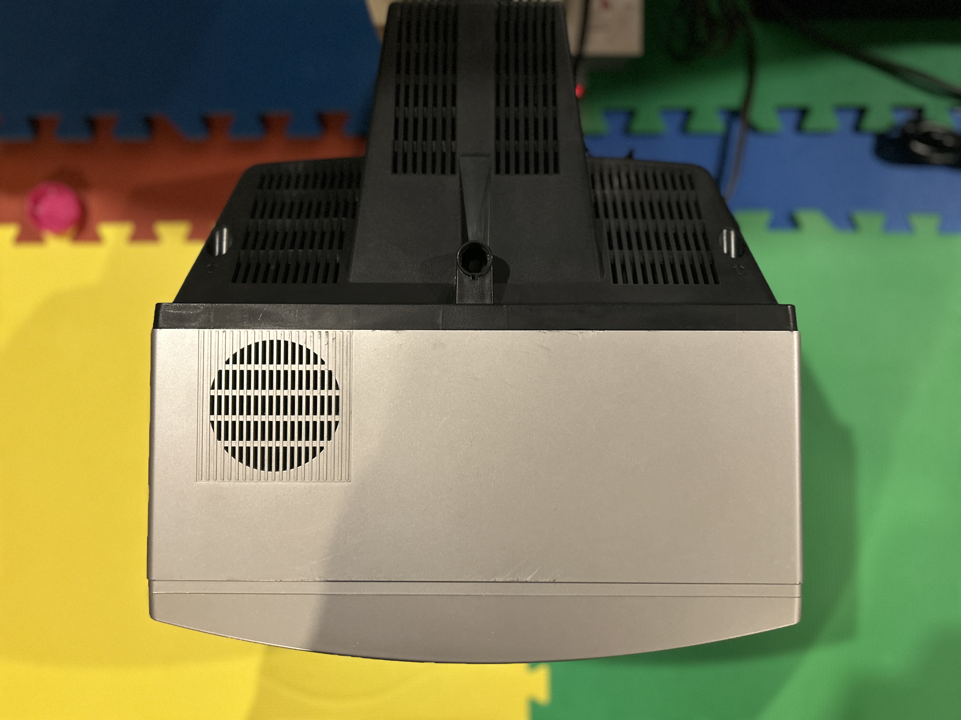
Front view 