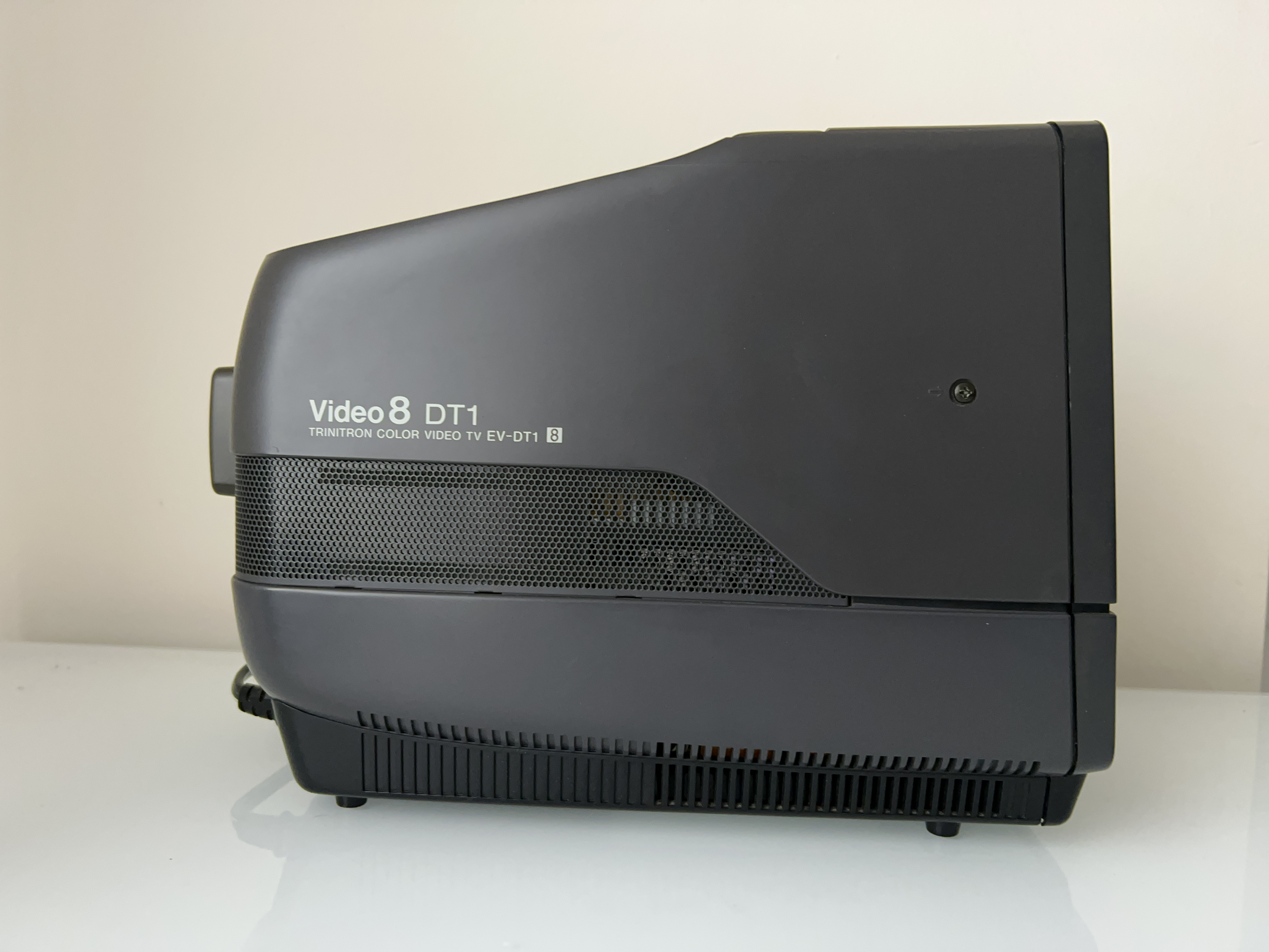
Sony EV-DT1 (NTSC) 5" CRT
Table of contents
Intro
In 1988, Sony introduced the EV-DT1 Video 8 Combo—a combination of a 5" Trinitron color CRT and VCR capable of both playing and recording 8mm Video 8 tapes.
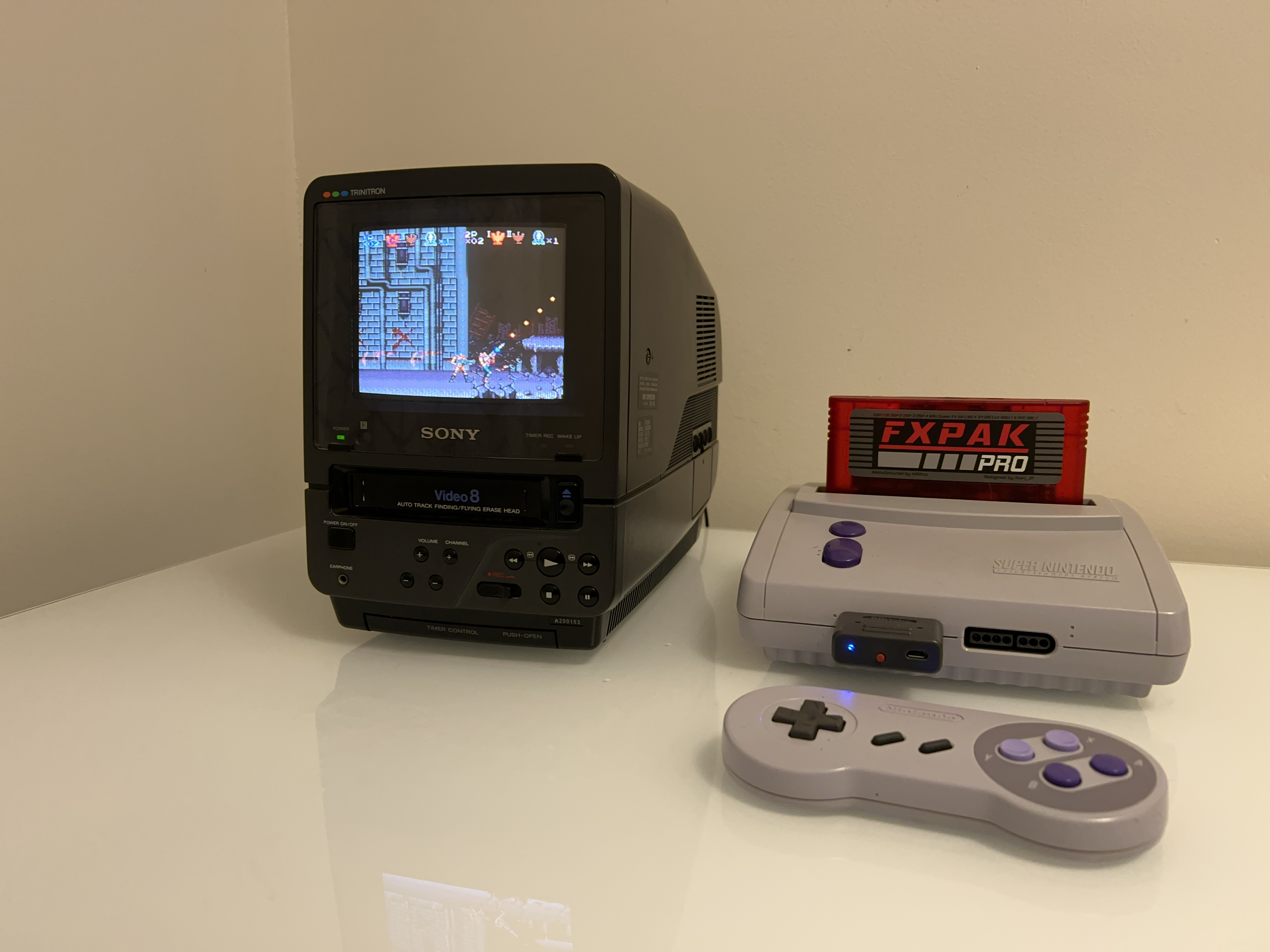
Video input - SNES (Metroid) 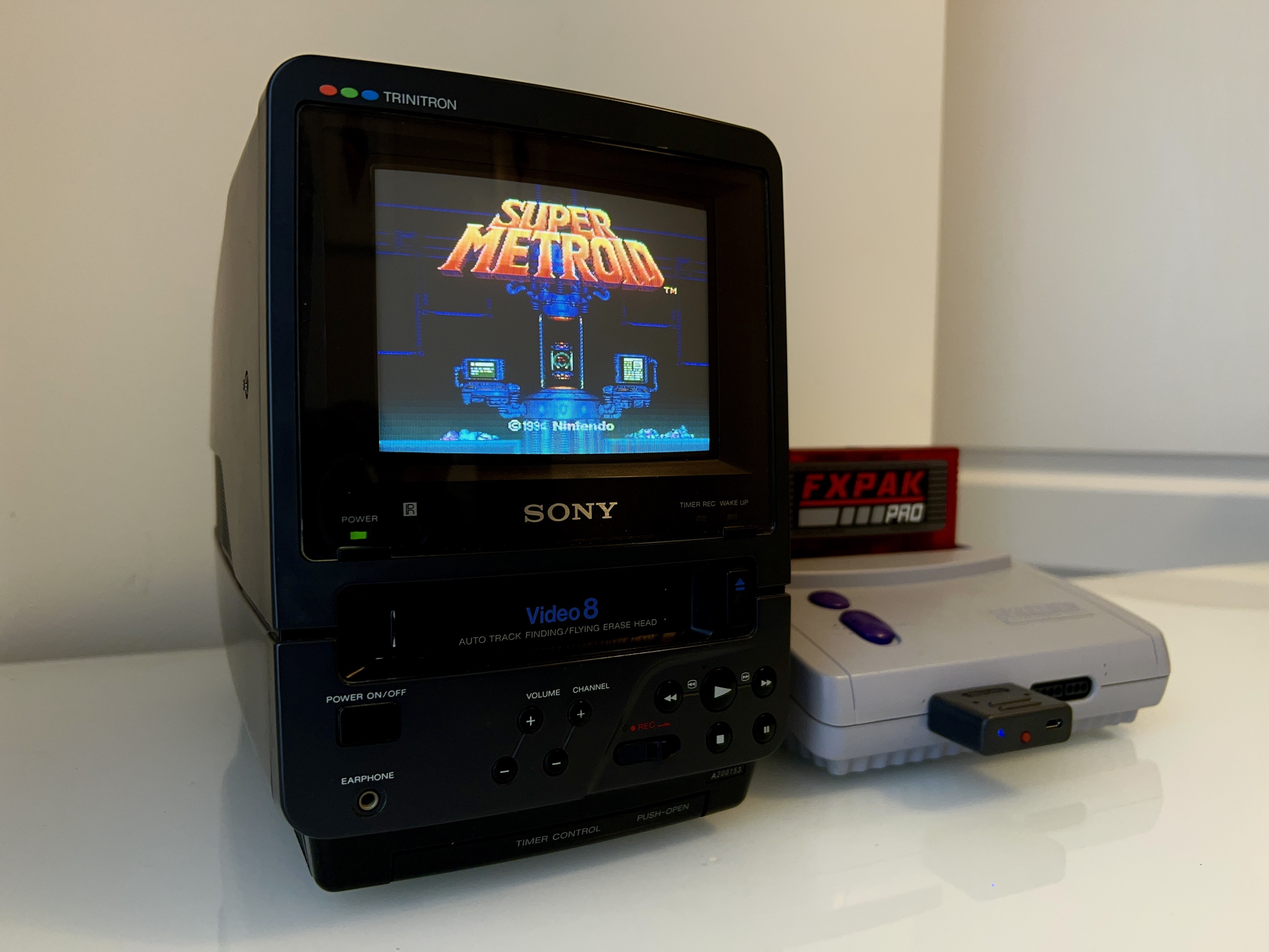
Video input - SNES (Contra III) 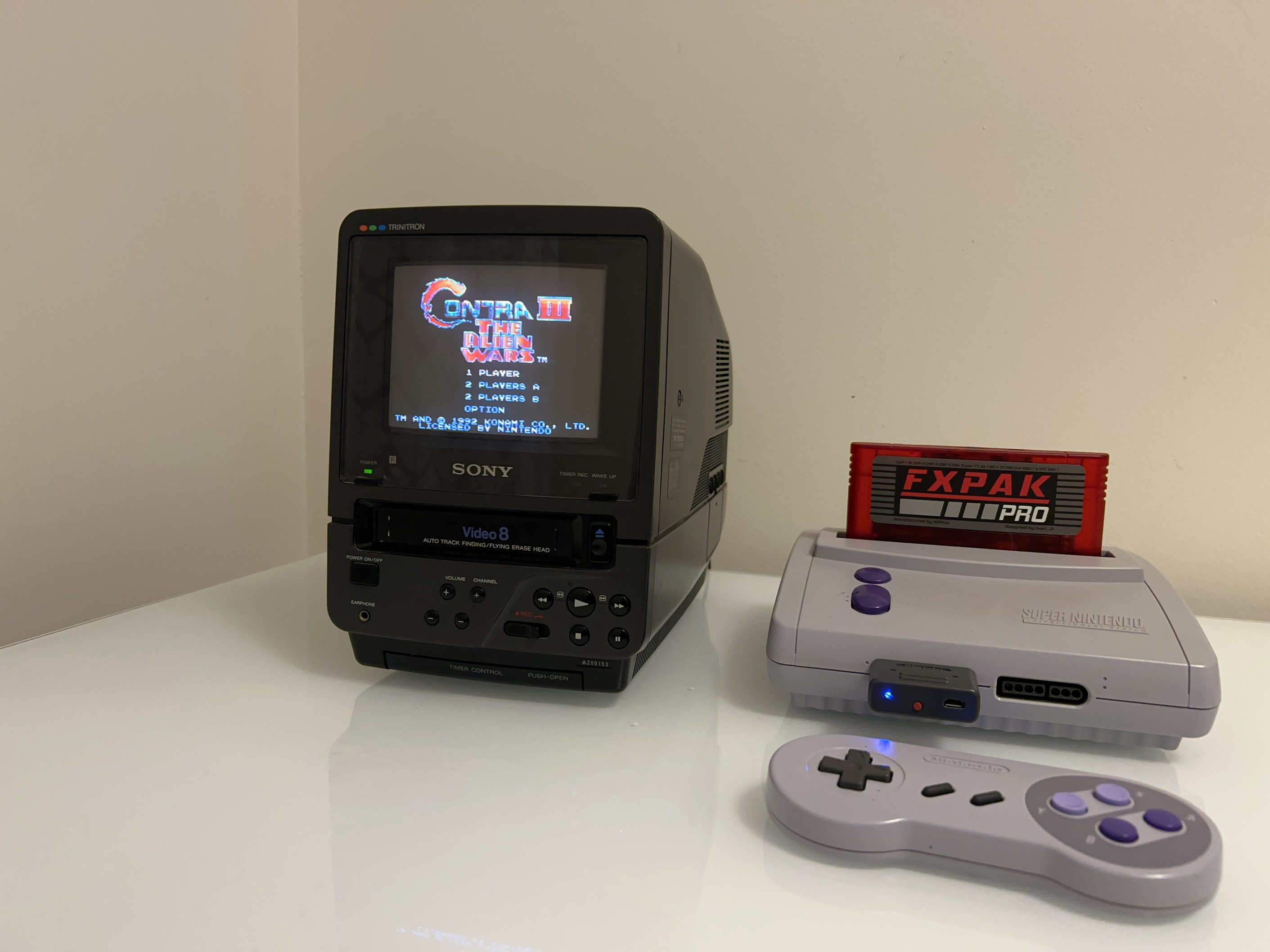
Video8 Playback 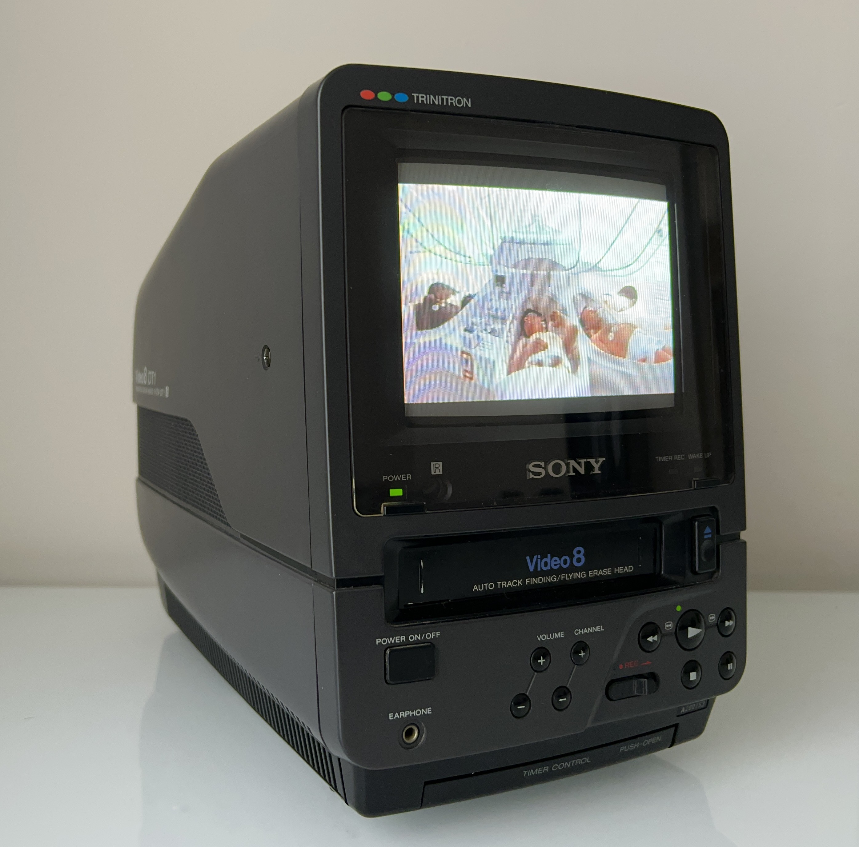
Sony Corp. of America has introduced two portable video products for personal use that the company predicts will revolutionize the electronics industry and the way people use video.
The products are the GV-8 Video Walkman TV-VCR combination unit, a portable hand-held unit about the size of a book, and the slightly larger EV-DT1 desktop video system.
The EV-DT1, available now for about $1,700, is a complete video unit designed for desktop use. It takes up little more room than a telephone, contains a 5-inch color monitor and a full-featured VCR with a seven-day, three-event timer with on-screen display.
Washington Post (Jun 6, 1988)
User and Service Manuals
You can read more about the specs of this unit in the brochure or user manual.
PAL service manual is the only one I have. It seems very close to the NTSC version. If you happen to have the NTSC service manual, please consider sharing it.
Specs
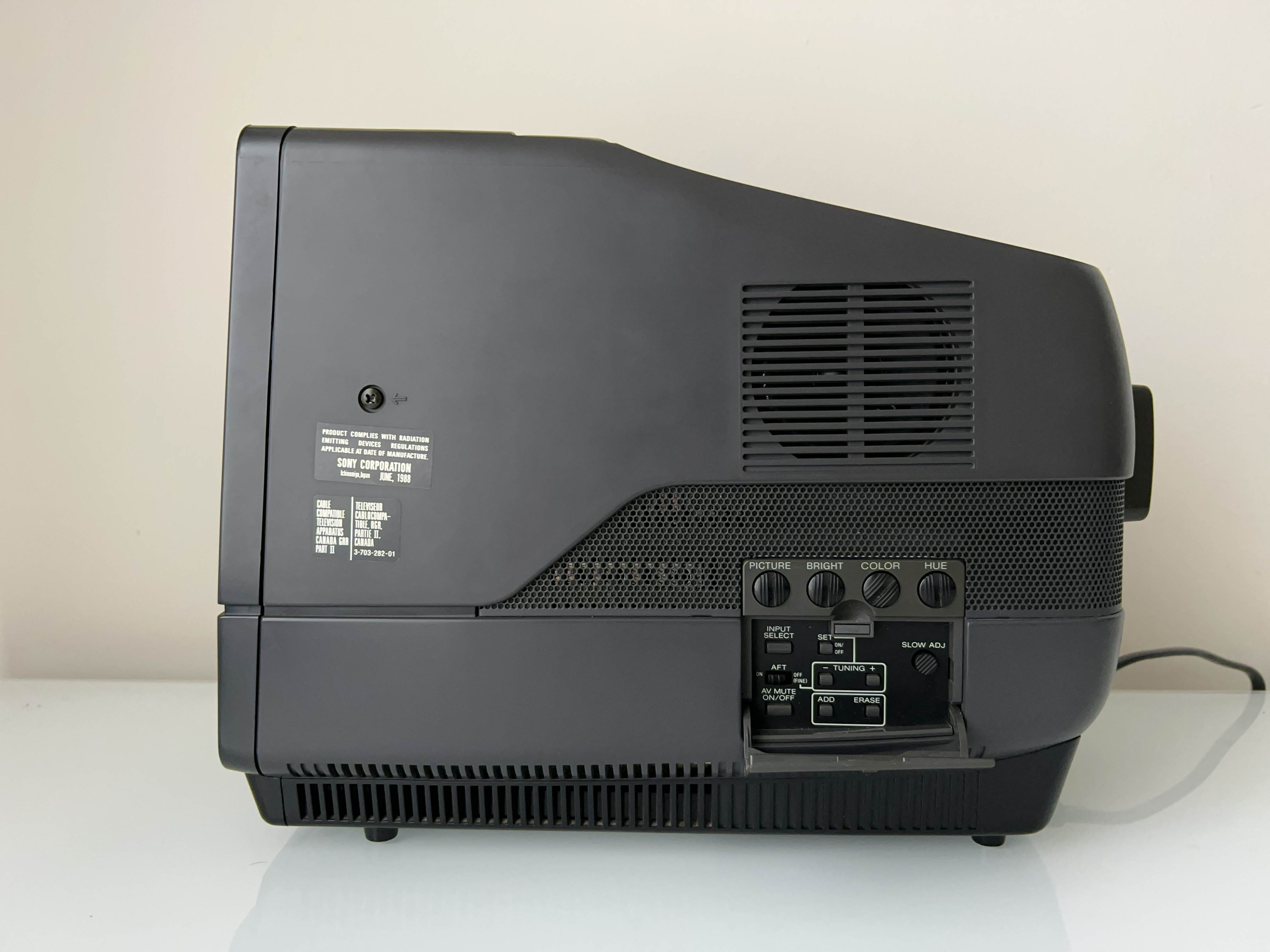
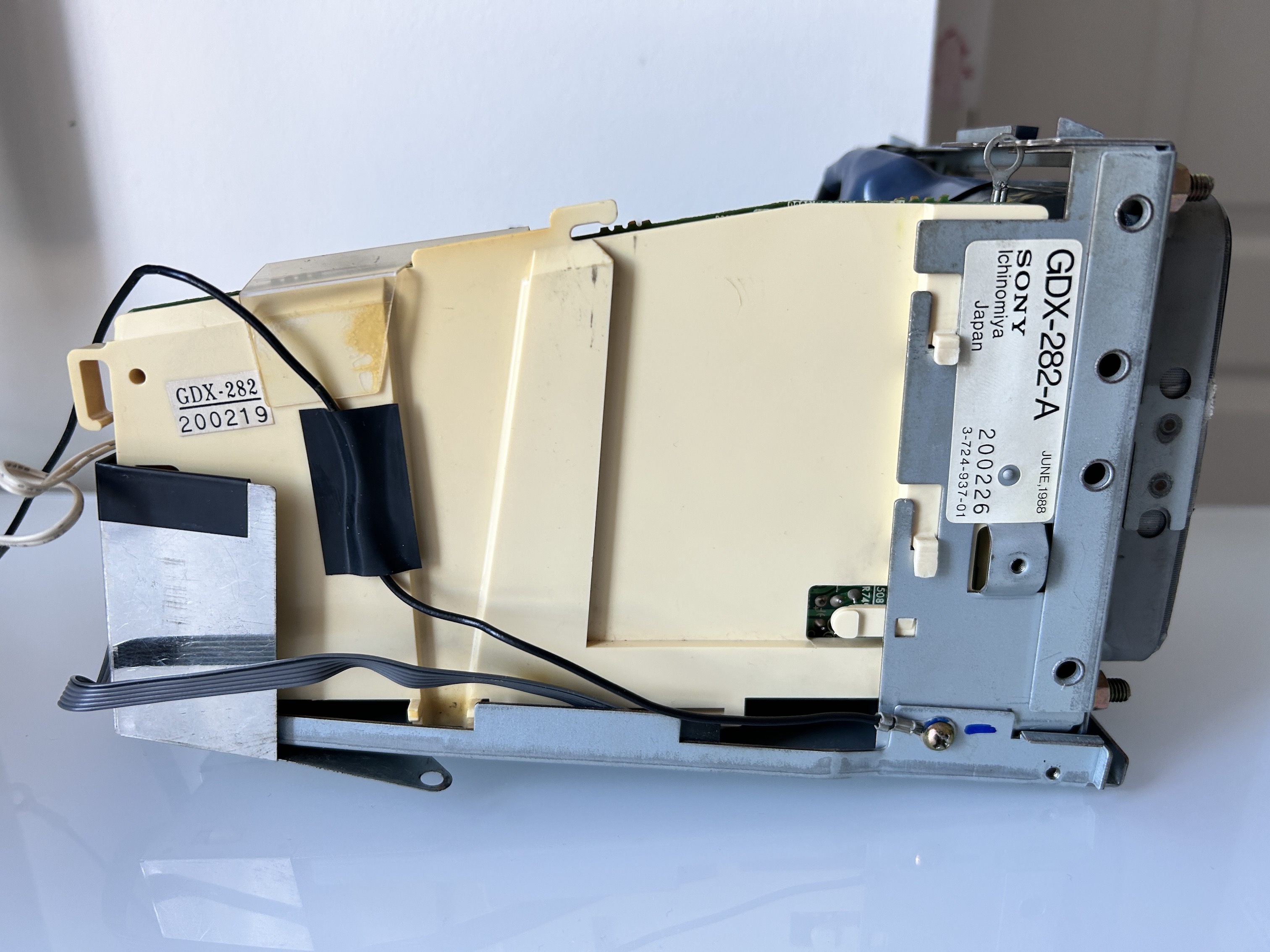
- Manufactured: June 1988
- NTSC, 60 Hz
- Speakers: 8 ohms, 700mW
- Remote: RMT-442
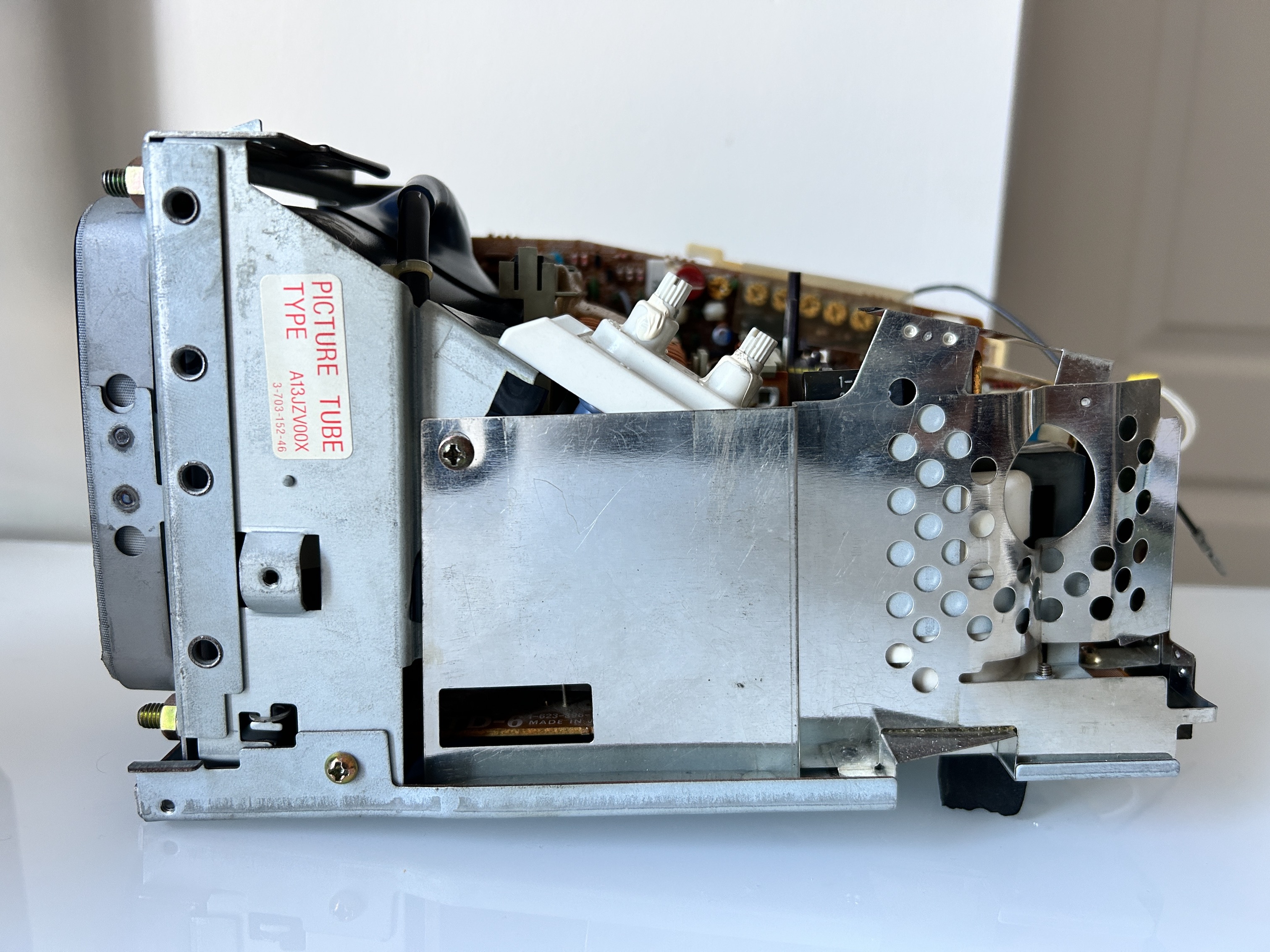
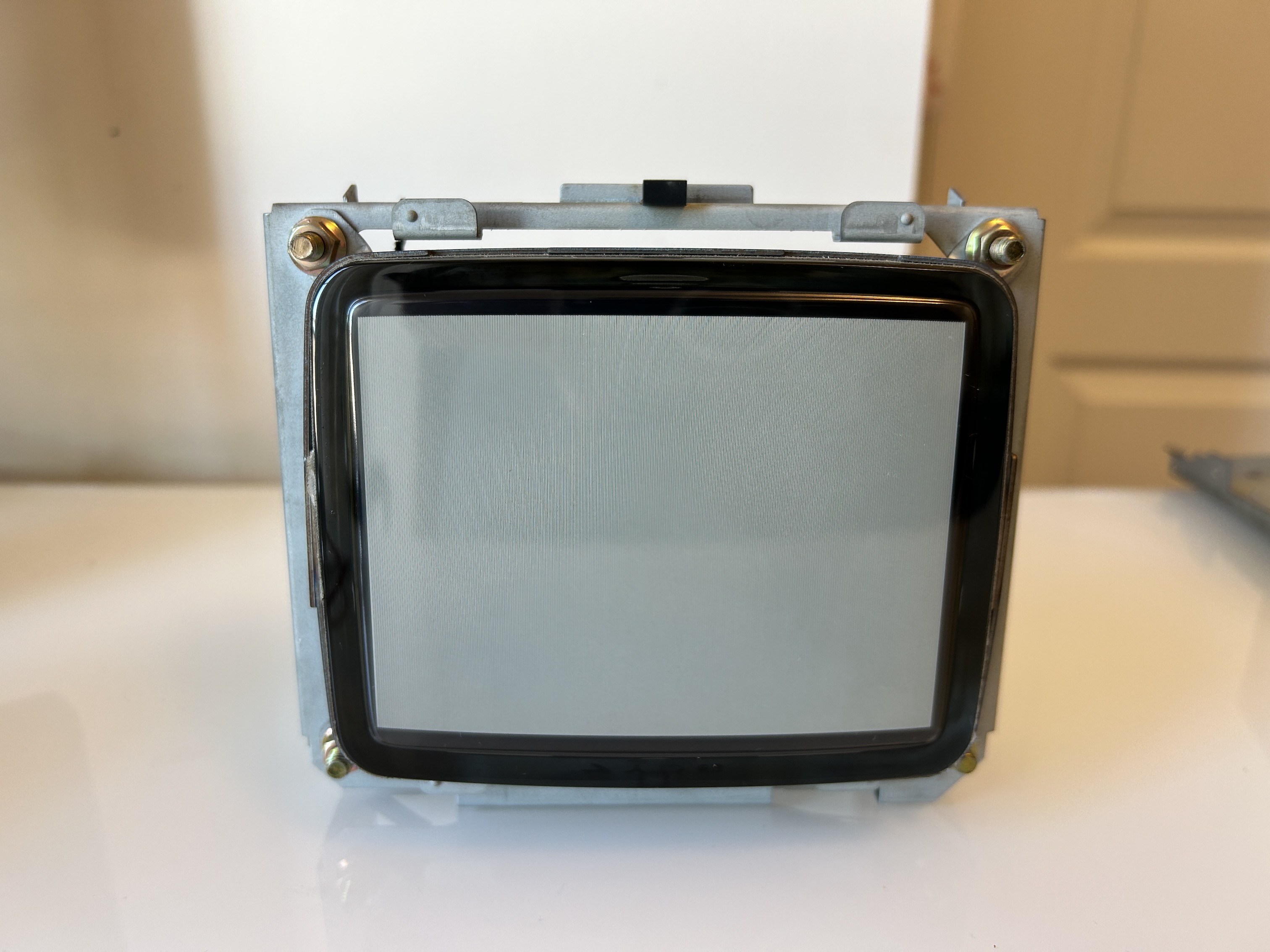
- Picture Tube: Trinitron A13JZV00X (also used in Sony PVM-5041Q)
- Video recording system: Rotary two-head helical scanning FM system
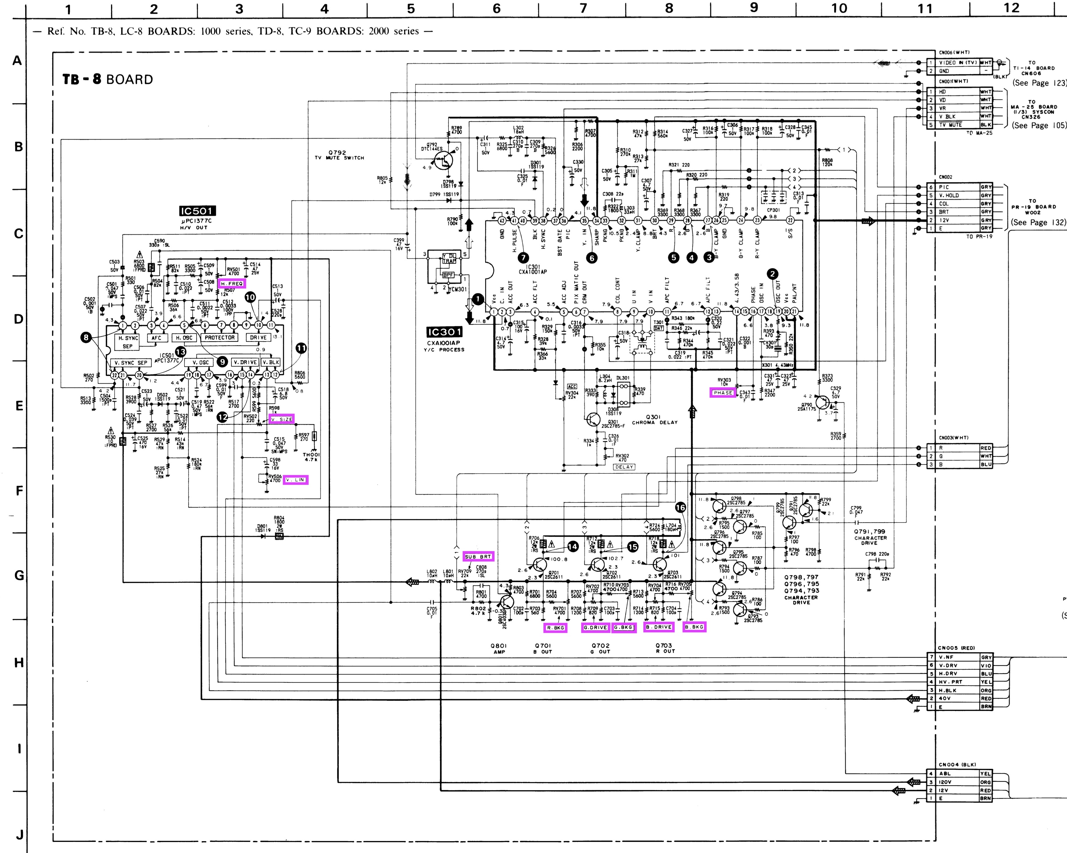
Sony EV-DT1 Schematics
Sony EV-DT1 PAL TV Schematics (NTSC has a very similar layout) 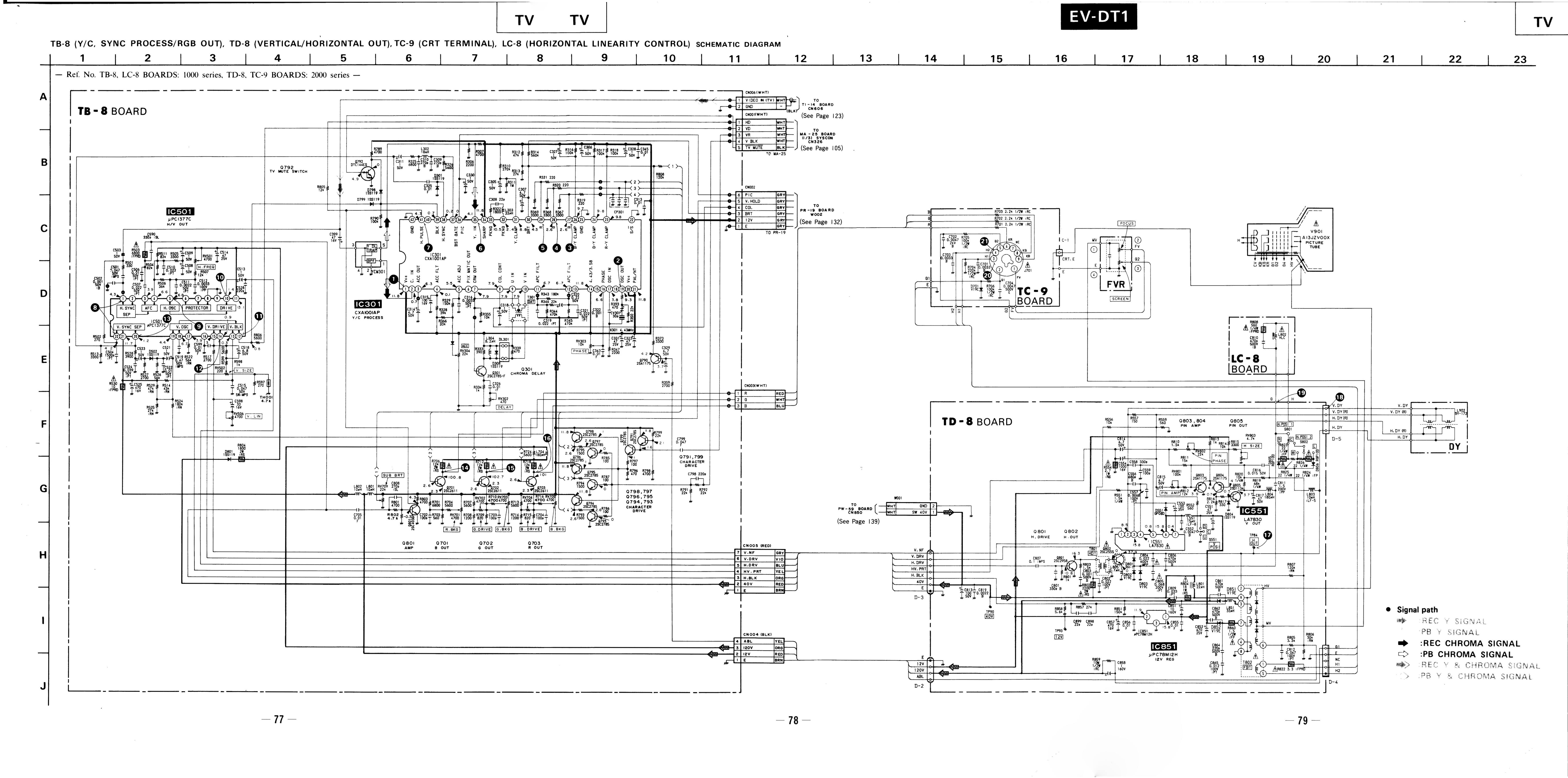
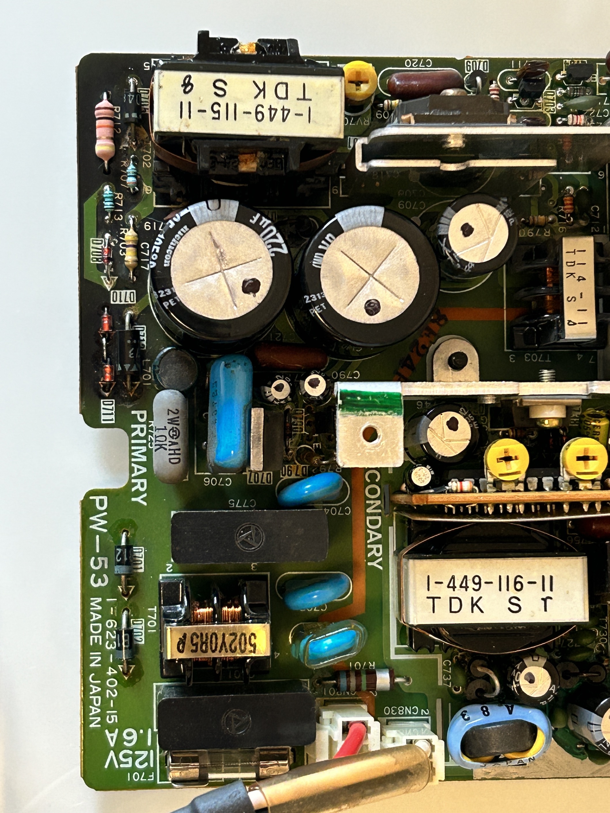
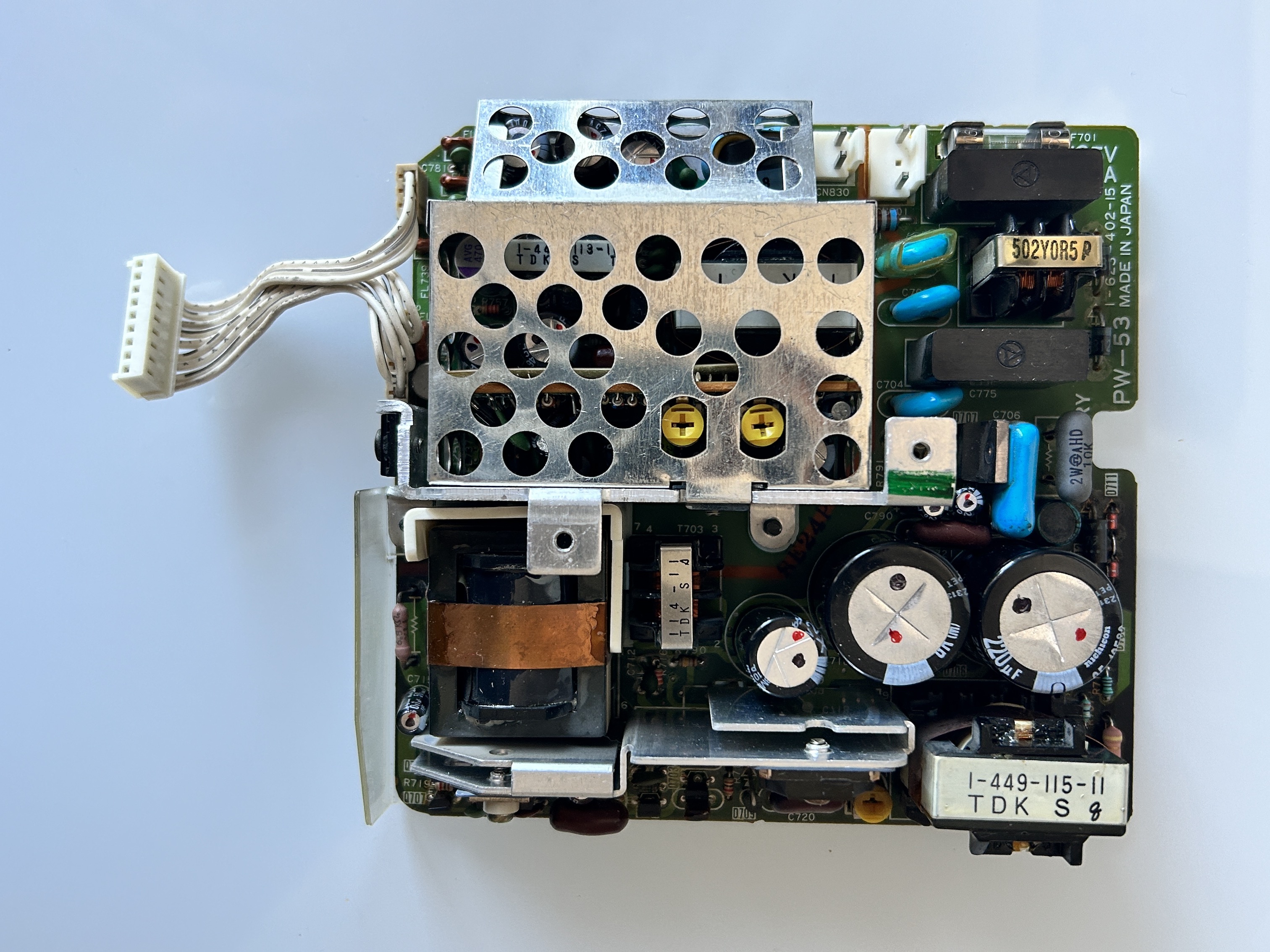
Power supply board (PW-53)
I got this off ebay as a non-working unit. I wanted to bring this to life. I tried powering on the set and there was absolutely no sign of life.
Removed the upper cabinet. Then had to remove PW-56 board to get to the power supply unit. Had to disconnect several wires. Once the power supply unit was out, removing a few screws brings you to the power supply board (PW-53).
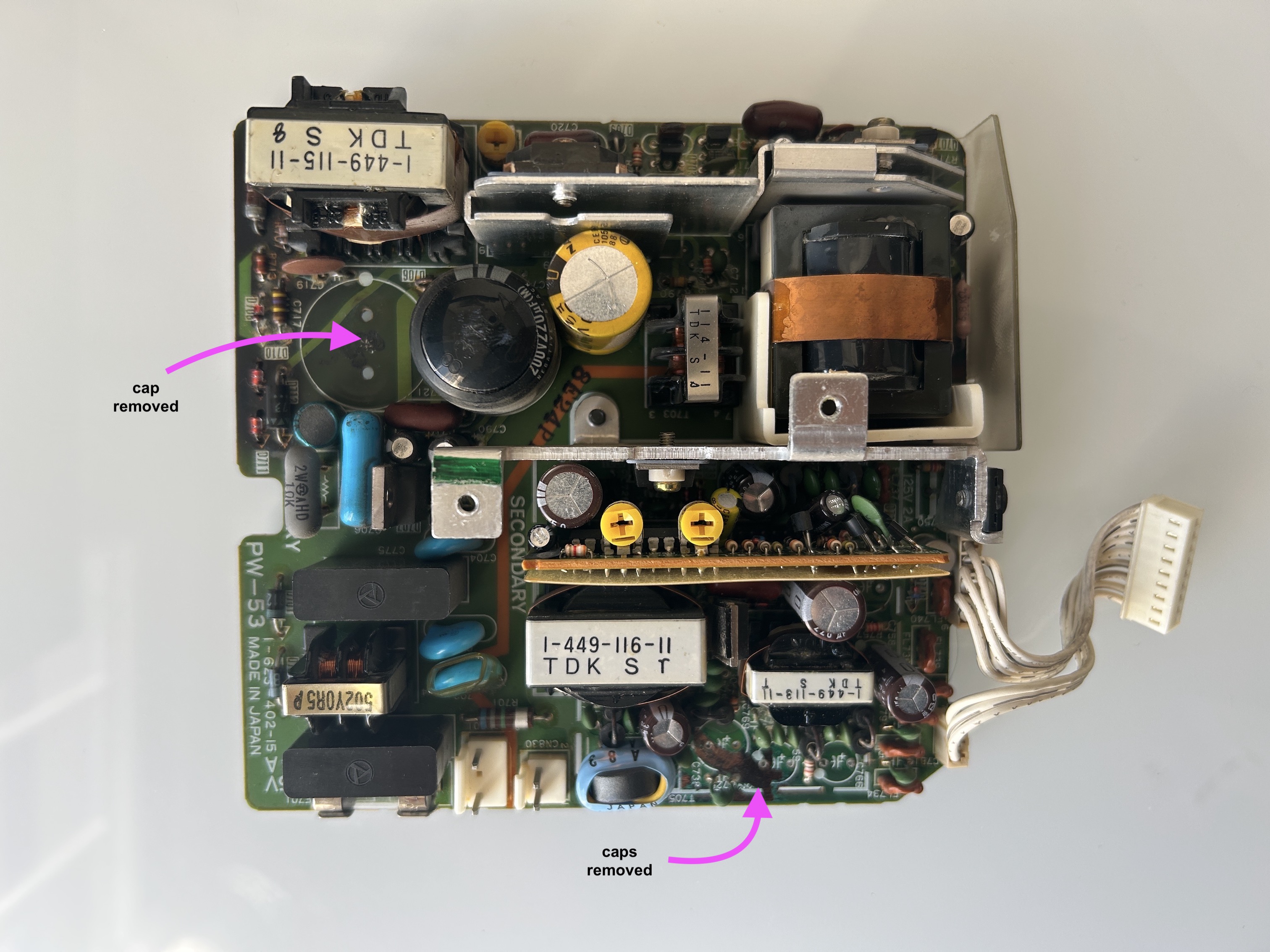
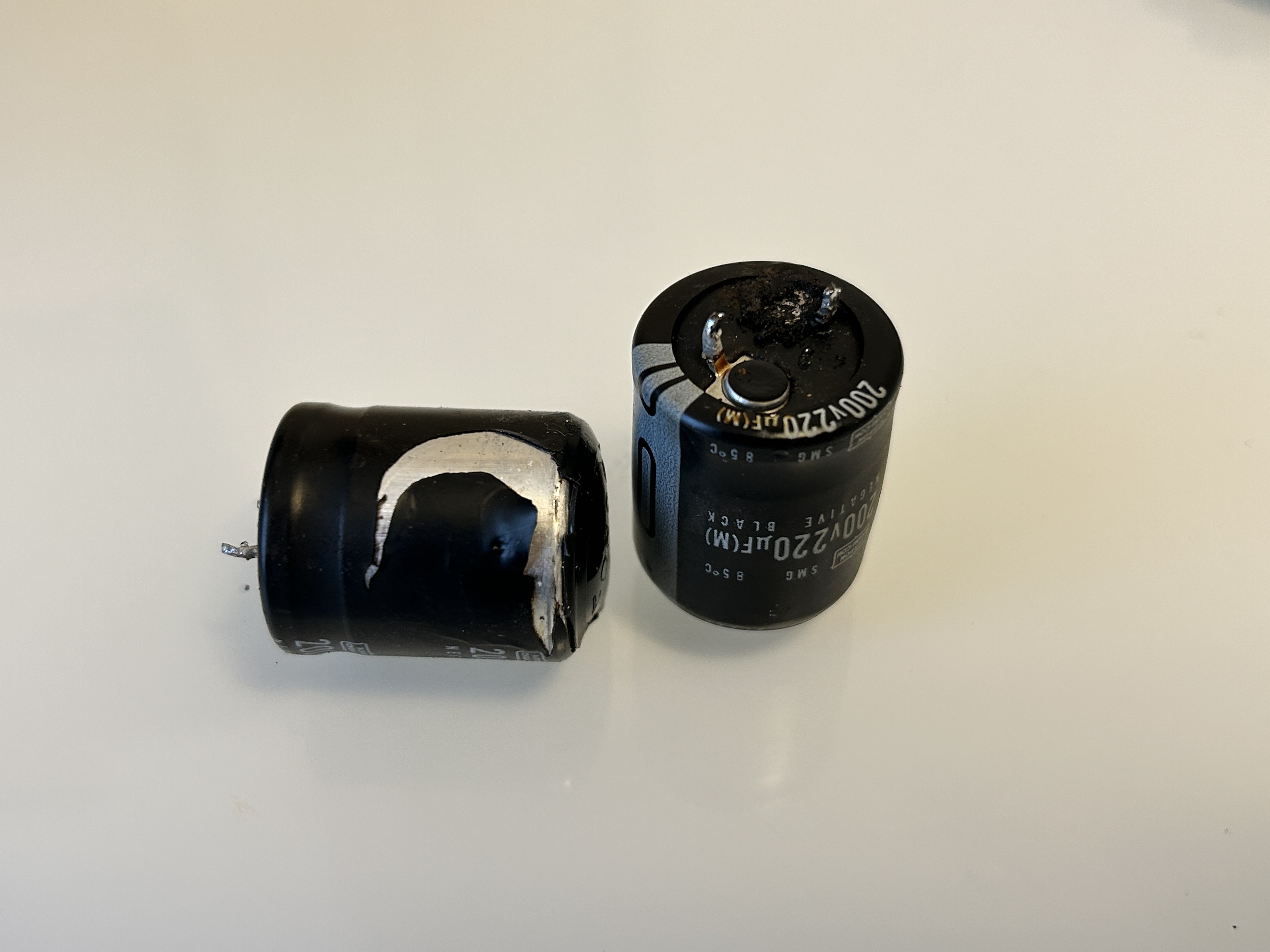
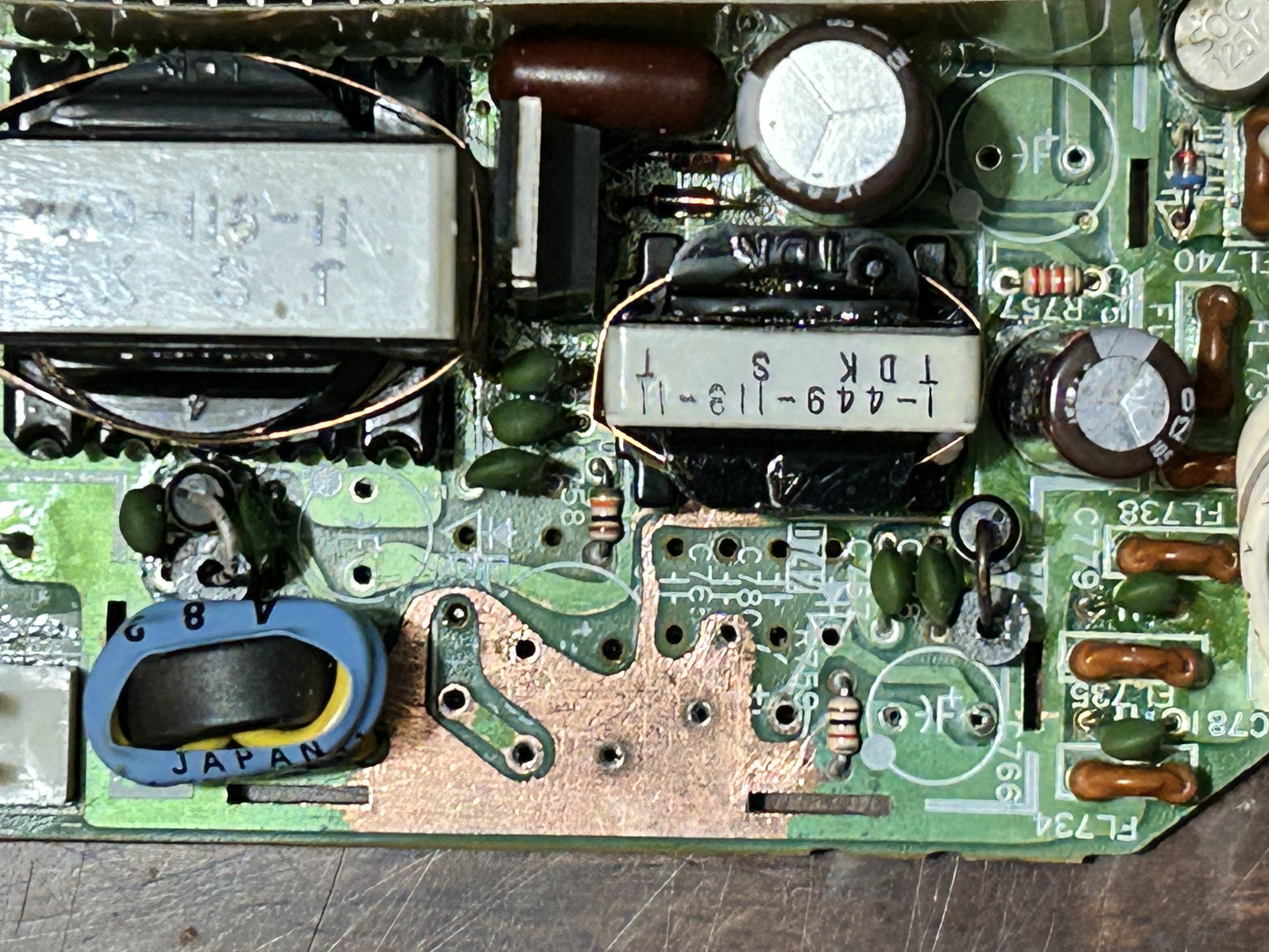
Without a surprise, several capacitors were completely blown. There was a lot of soot and, trace damage caused by leaking capacitors.
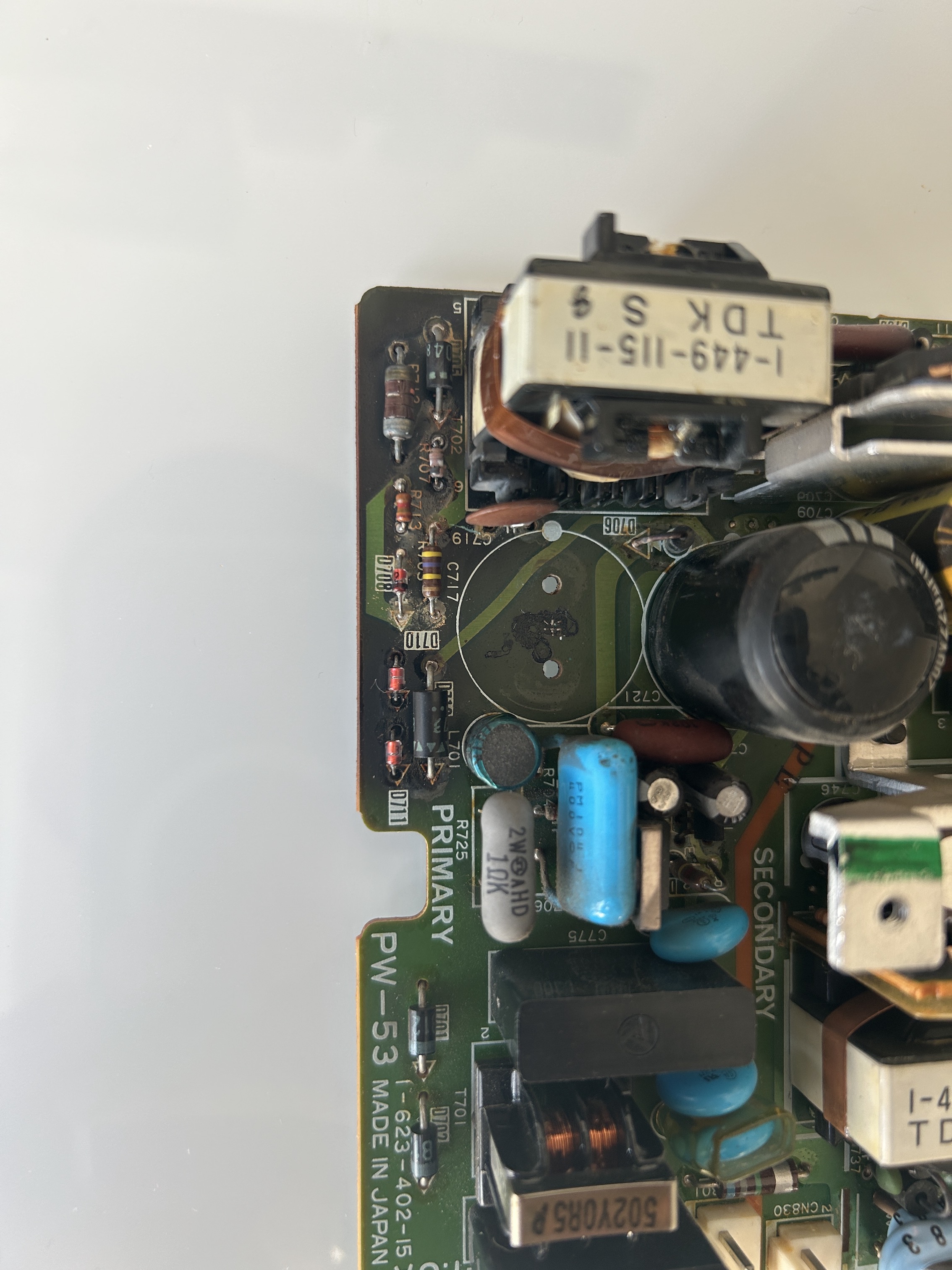
Corroded carbon resistors
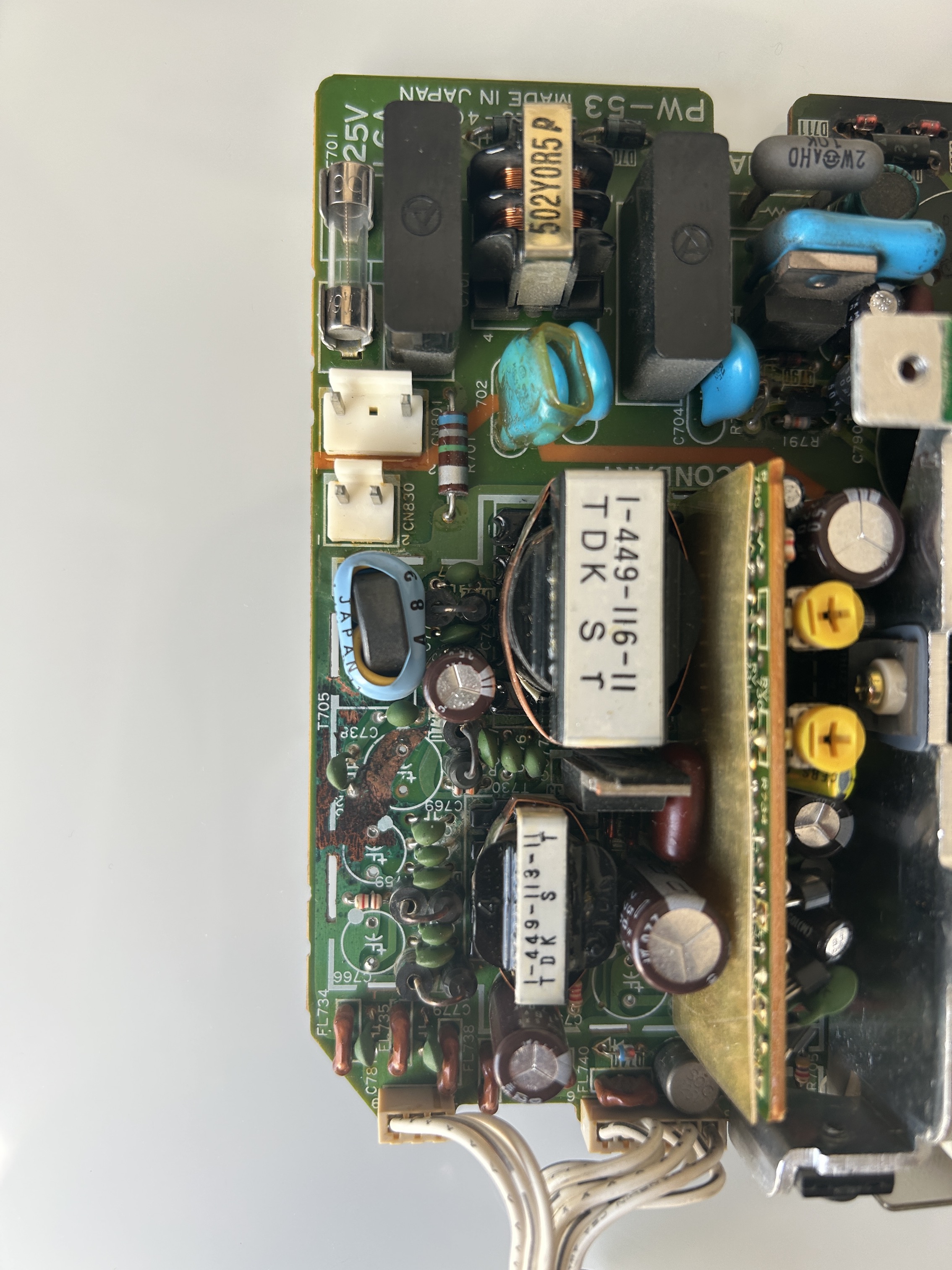
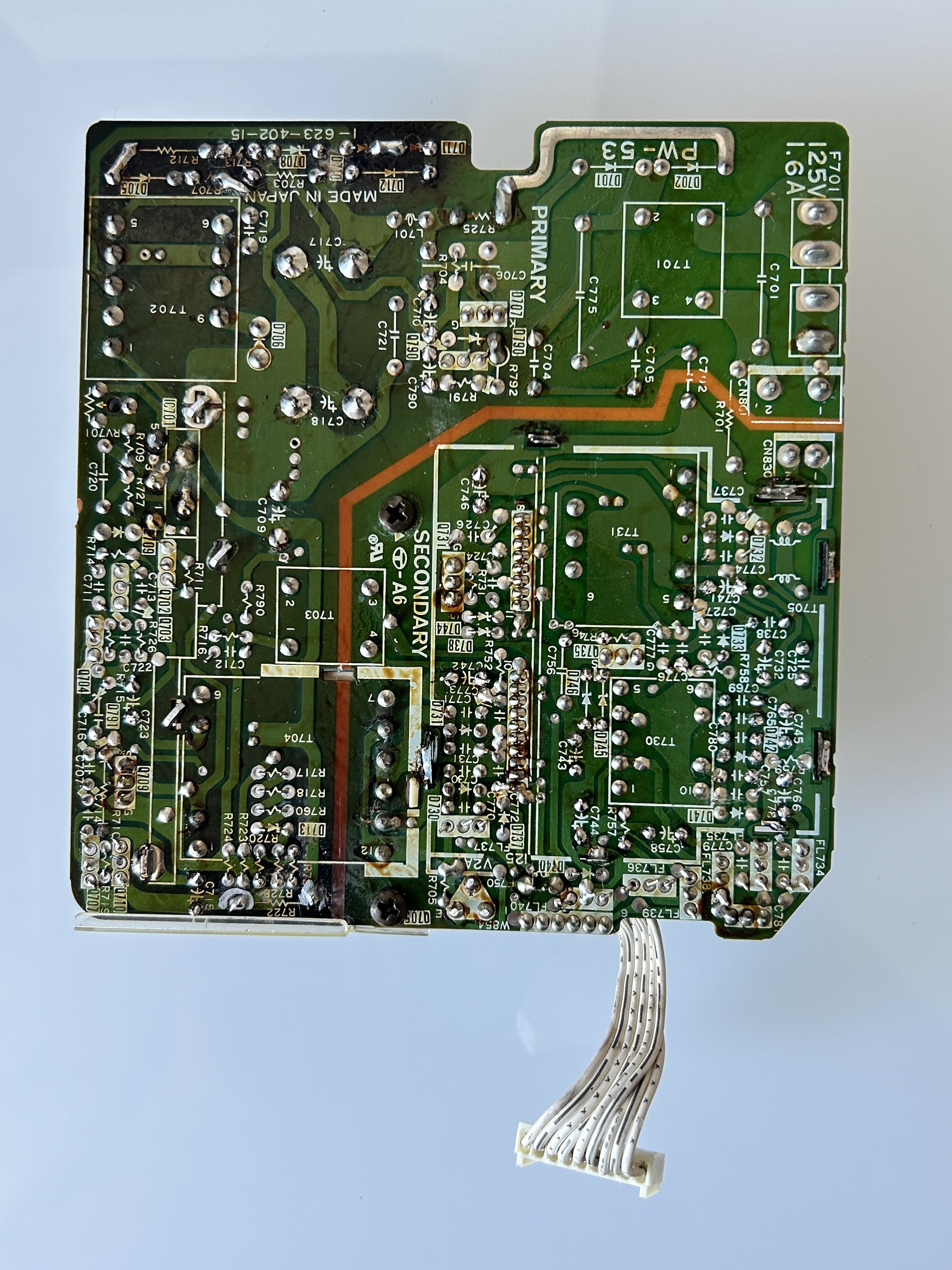
Leaked capacitors ate away some of the PCB. Pictures explain the situation well here.
First step was to clean the carbon residue with isopropyl alcohol, scrape and fix the damaged traces.
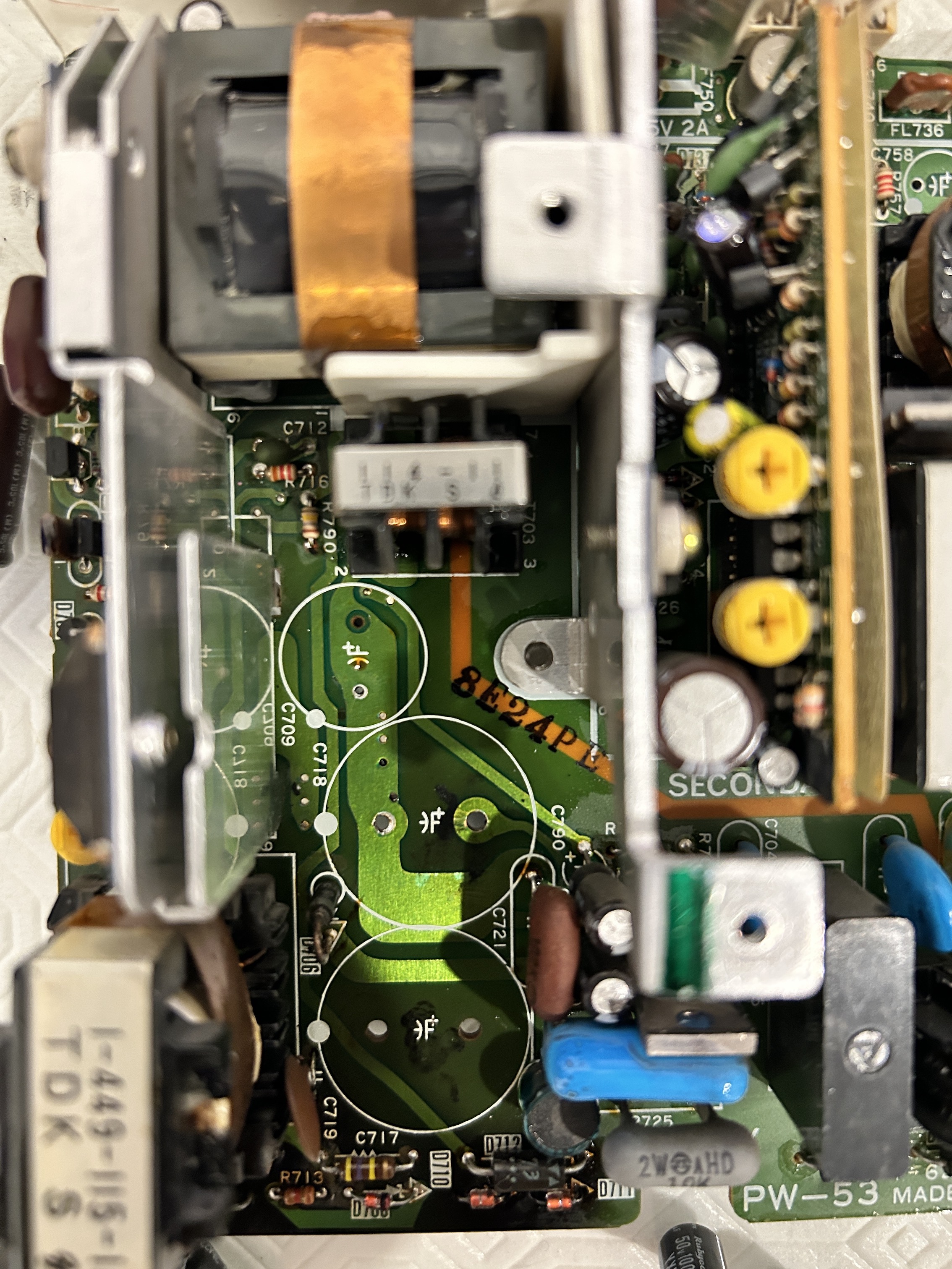
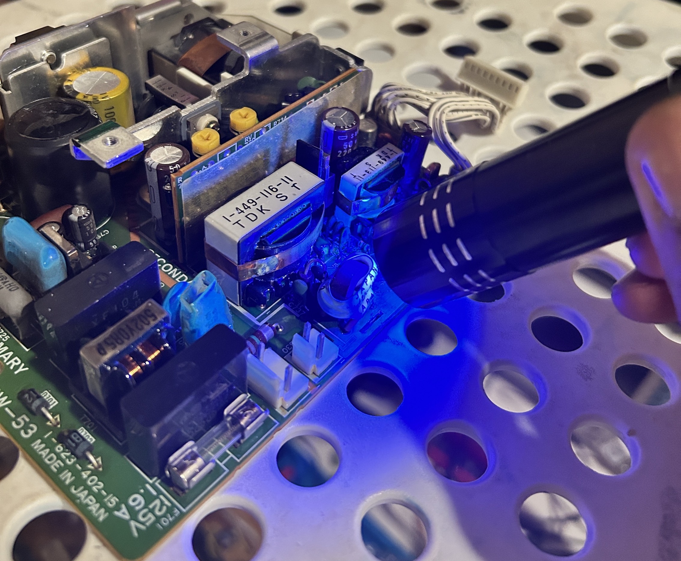
I applied a fresh solder mask, which was a novel experience for me, requiring a bit of effort to navigate. To facilitate the curing process, I found that the application of heat alongside UV light expedited the procedure.
Following the application of the solder mask, I decided to add an extra layer using a grey permanent marker.
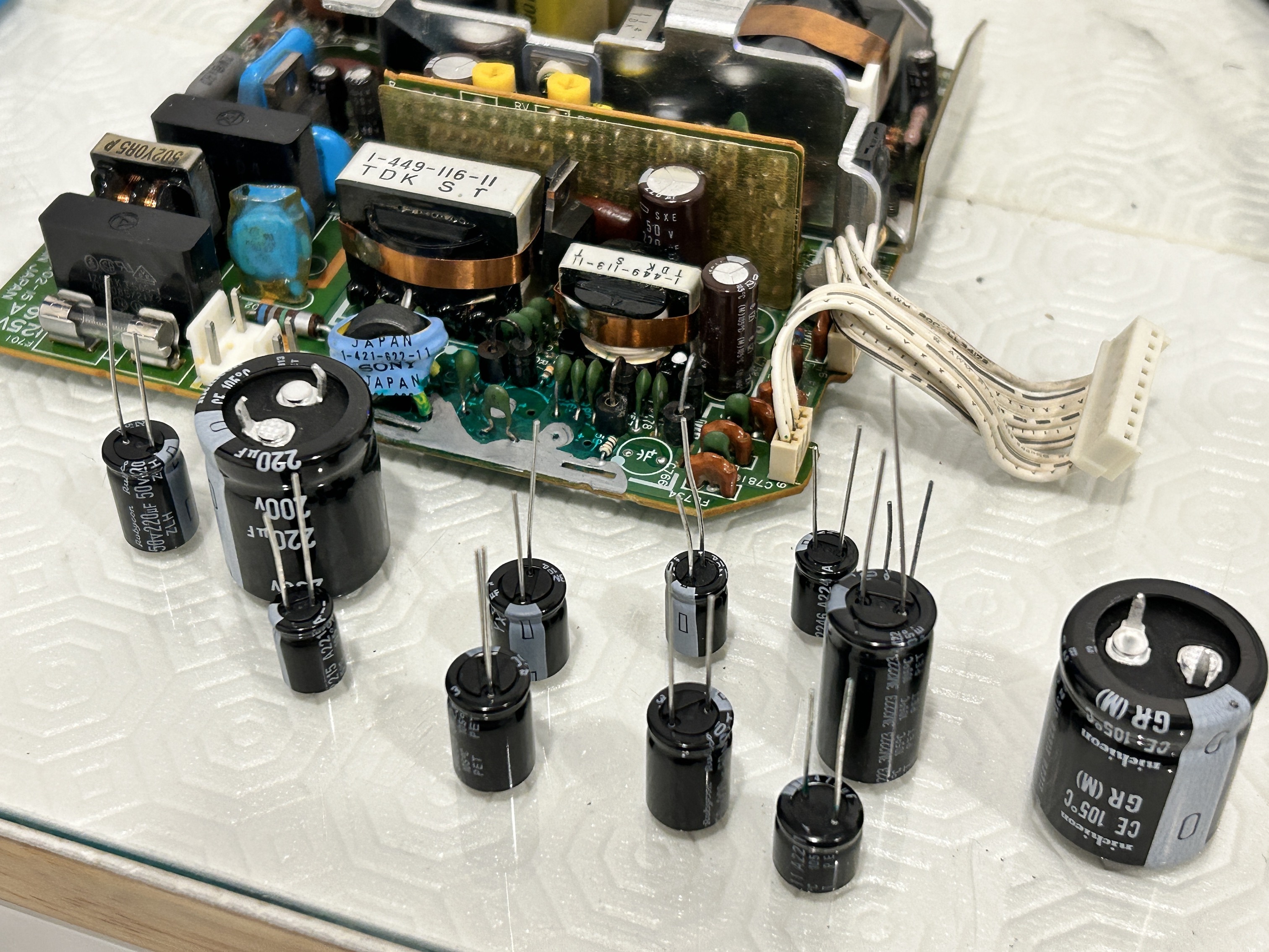
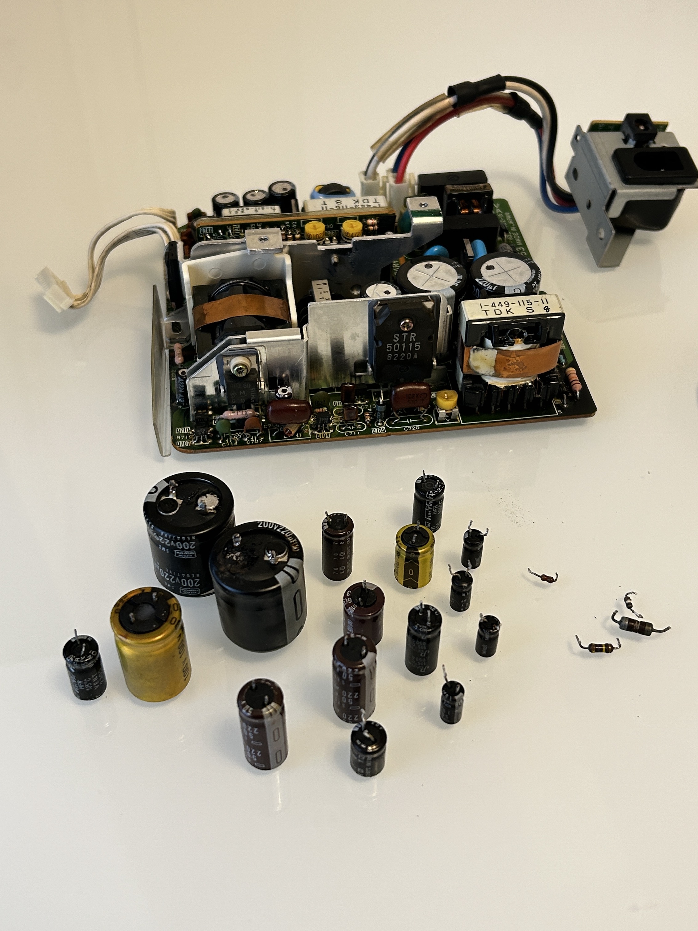
Replaced every single electrolytic capacitor, except two small capacitors that were on a small daughter board and was unreachable.
Replaced several out of spec, burnt carbon resistors with metal film resistors.
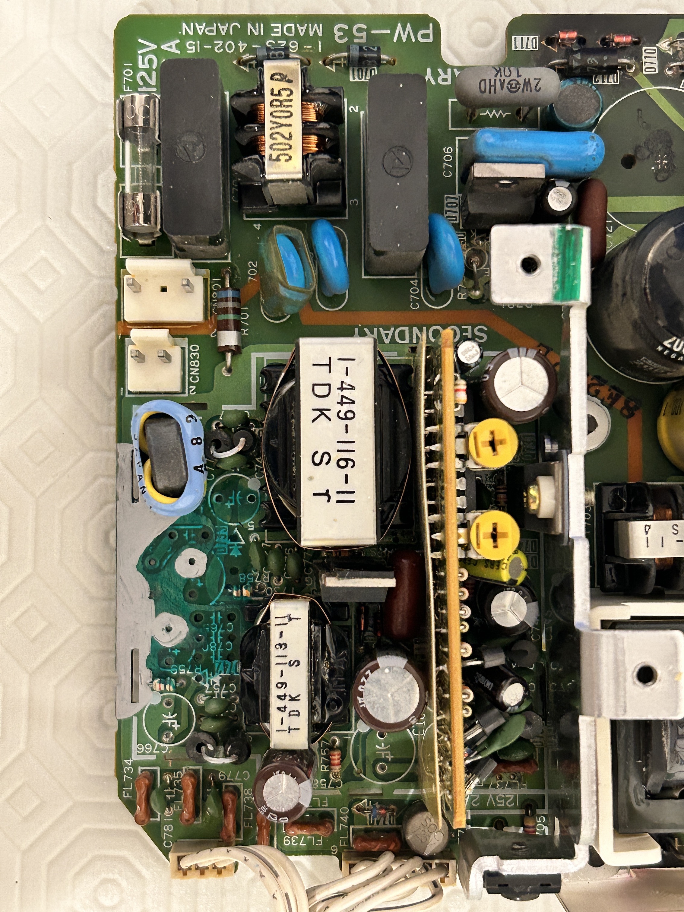
Had to reflow solder and fix several traces on the back
After changing the caps
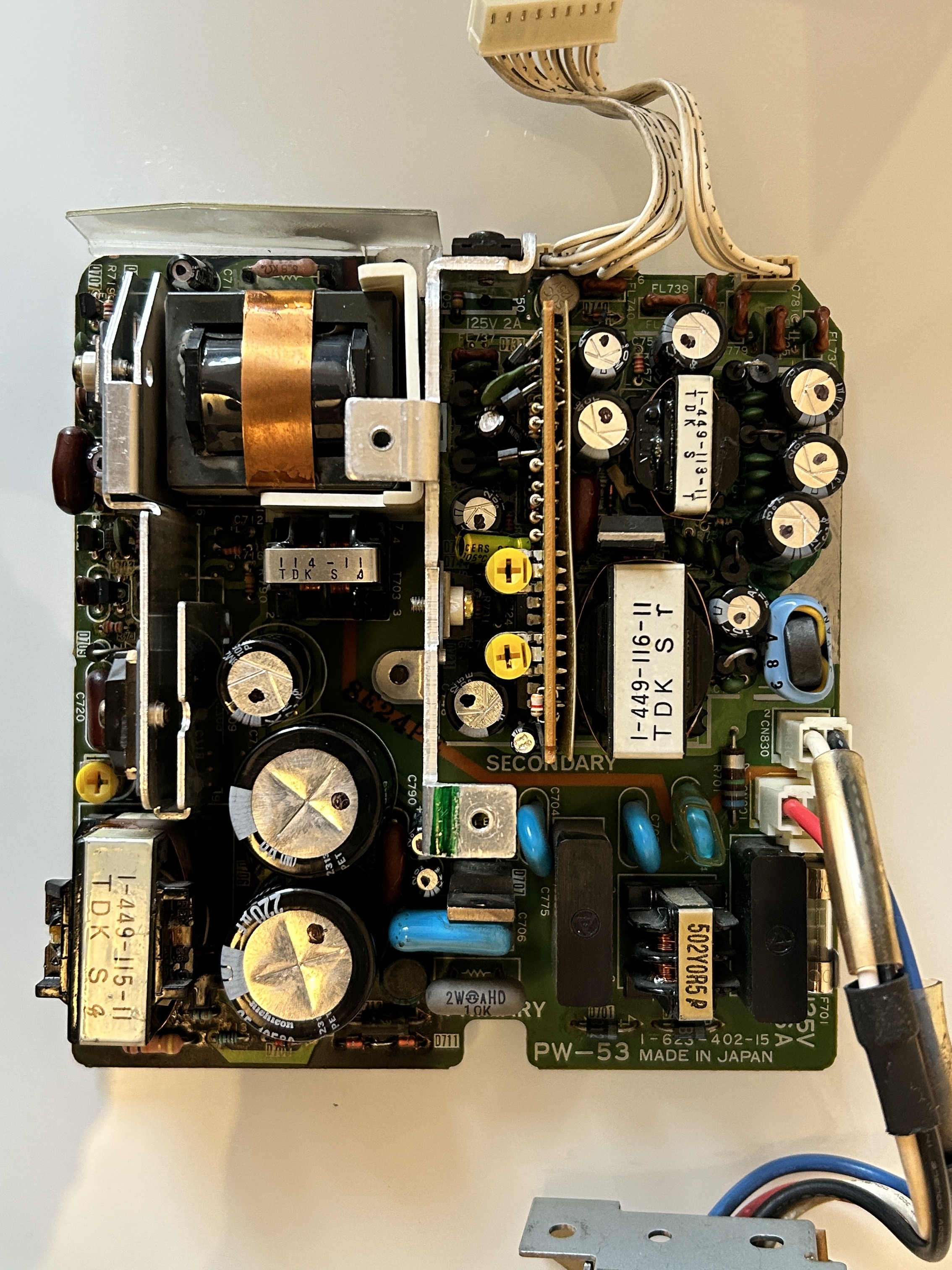
Final power supply board with caps, resistors replaced and metal shield added
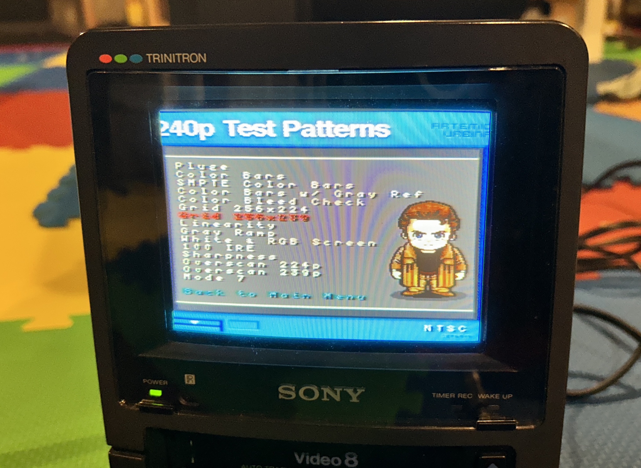
Turning on the CRT after replacing the caps
The positive development was that the CRT successfully powered on and functioned, and the Video 8 playback was operational as well. However, there was a noticeable horizontal overscan issue, indicating the necessity for further maintenance on additional boards.
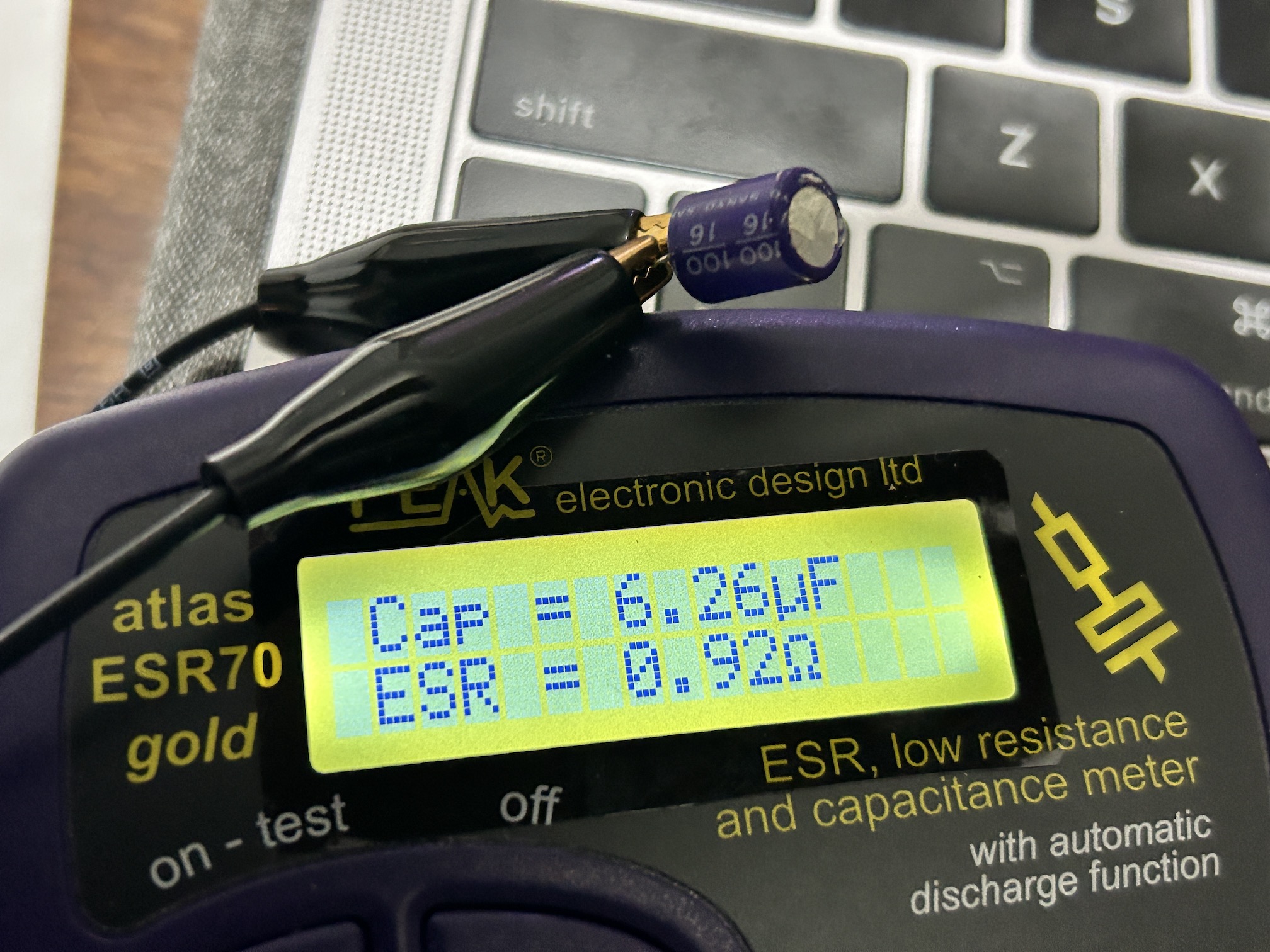
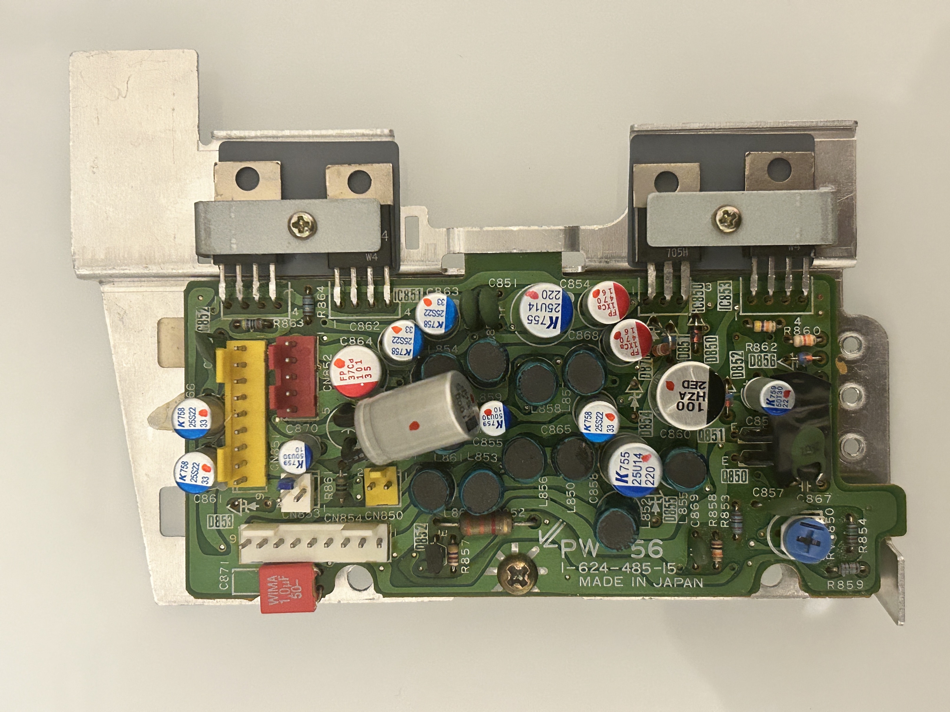
Regulator board (PW-56)
This board had an out of spec 100uF capacitor. Several solder joints were also cold and were ready to crack. Therefore, reflowed the board completely and decided to replace all caps with organic solid polymer/film capacitors.
Deflection board (TD-6)
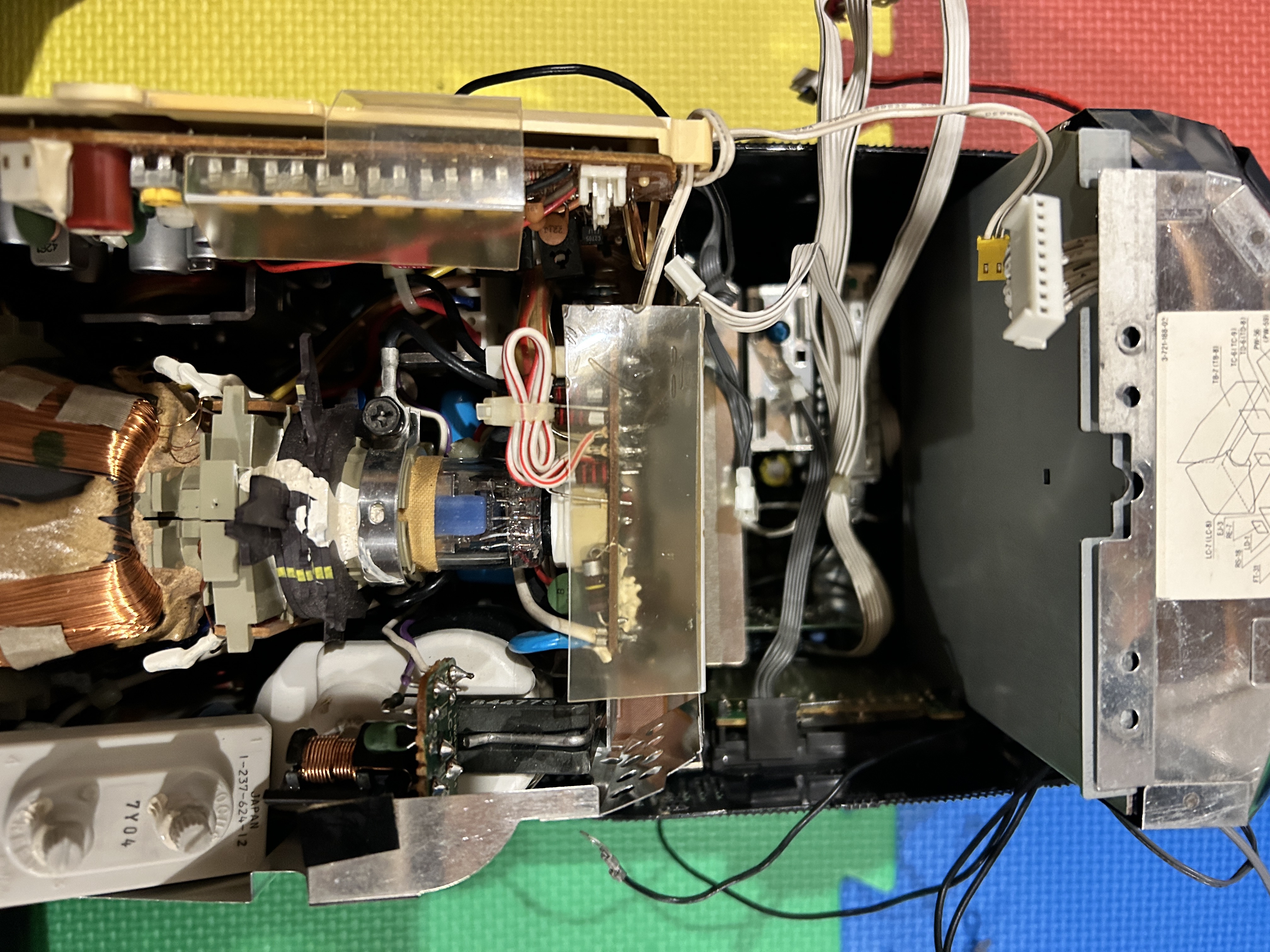
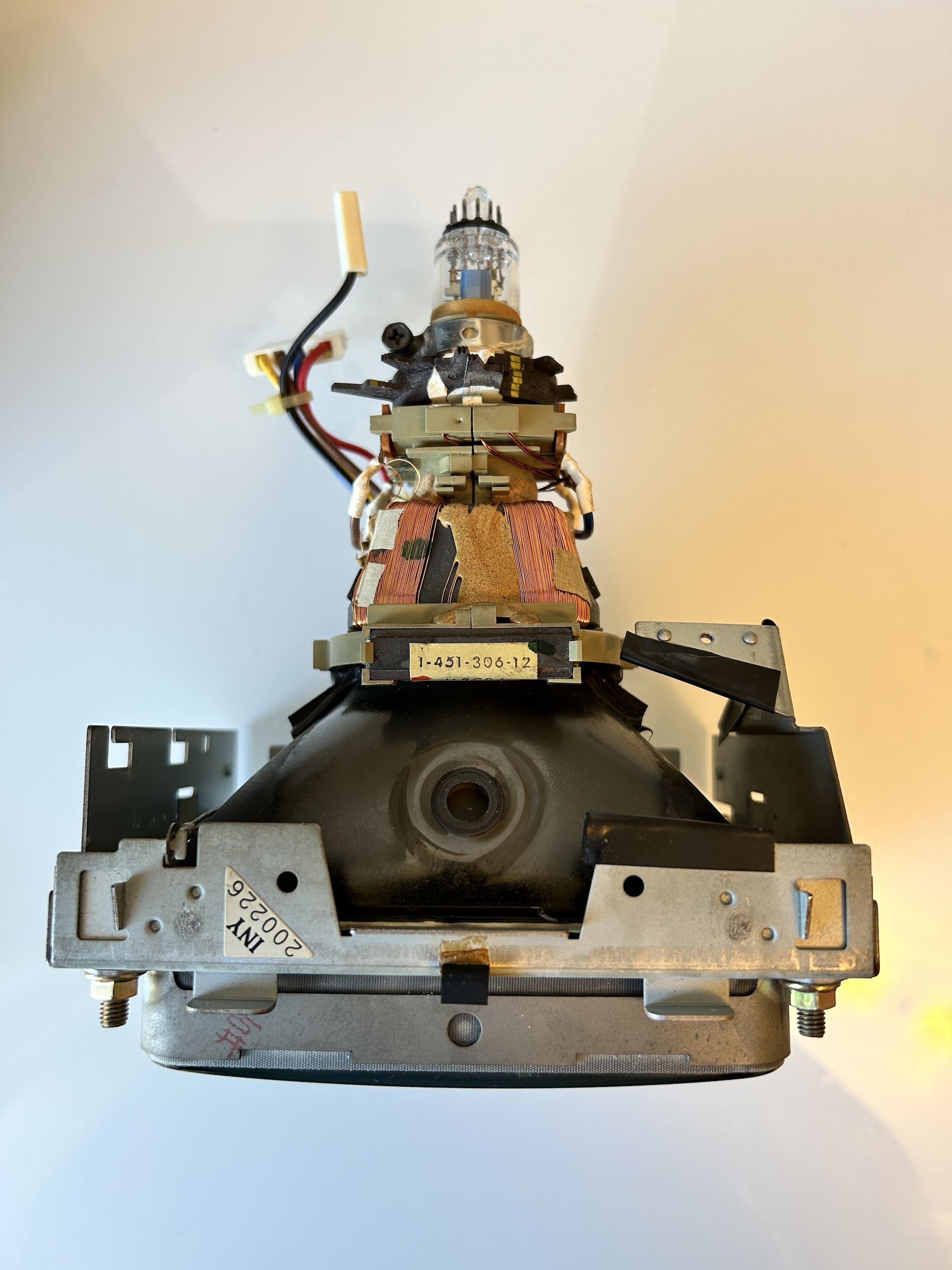
To get to the deflection board, the tube assembly needs to be taken out first.
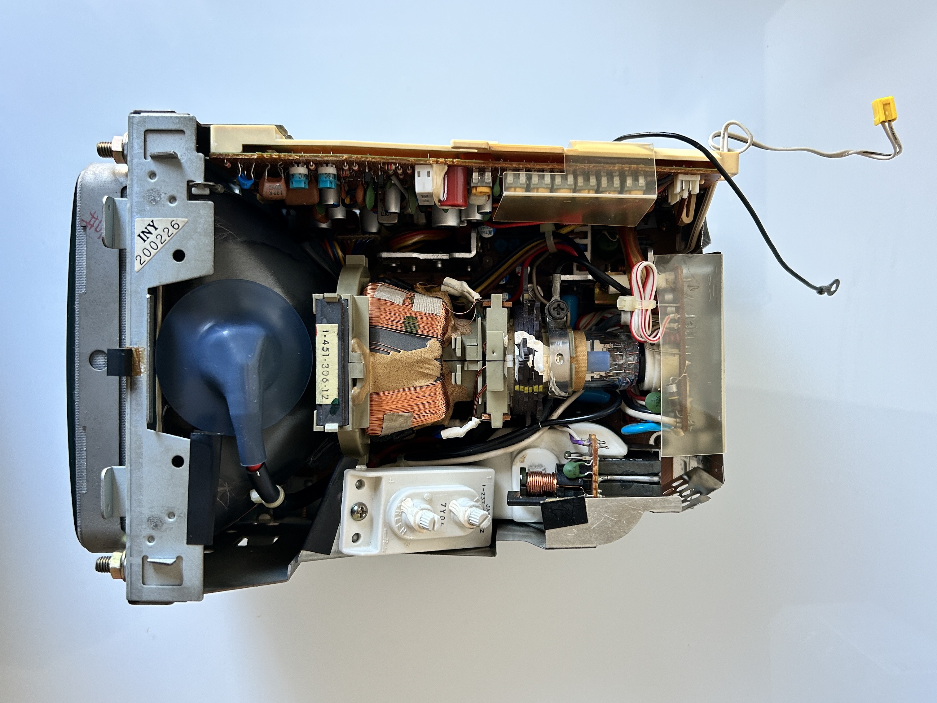
Then the tube should be separated out. Metal shield should be removed.
Remove the anode cap, flyback pots, neck board
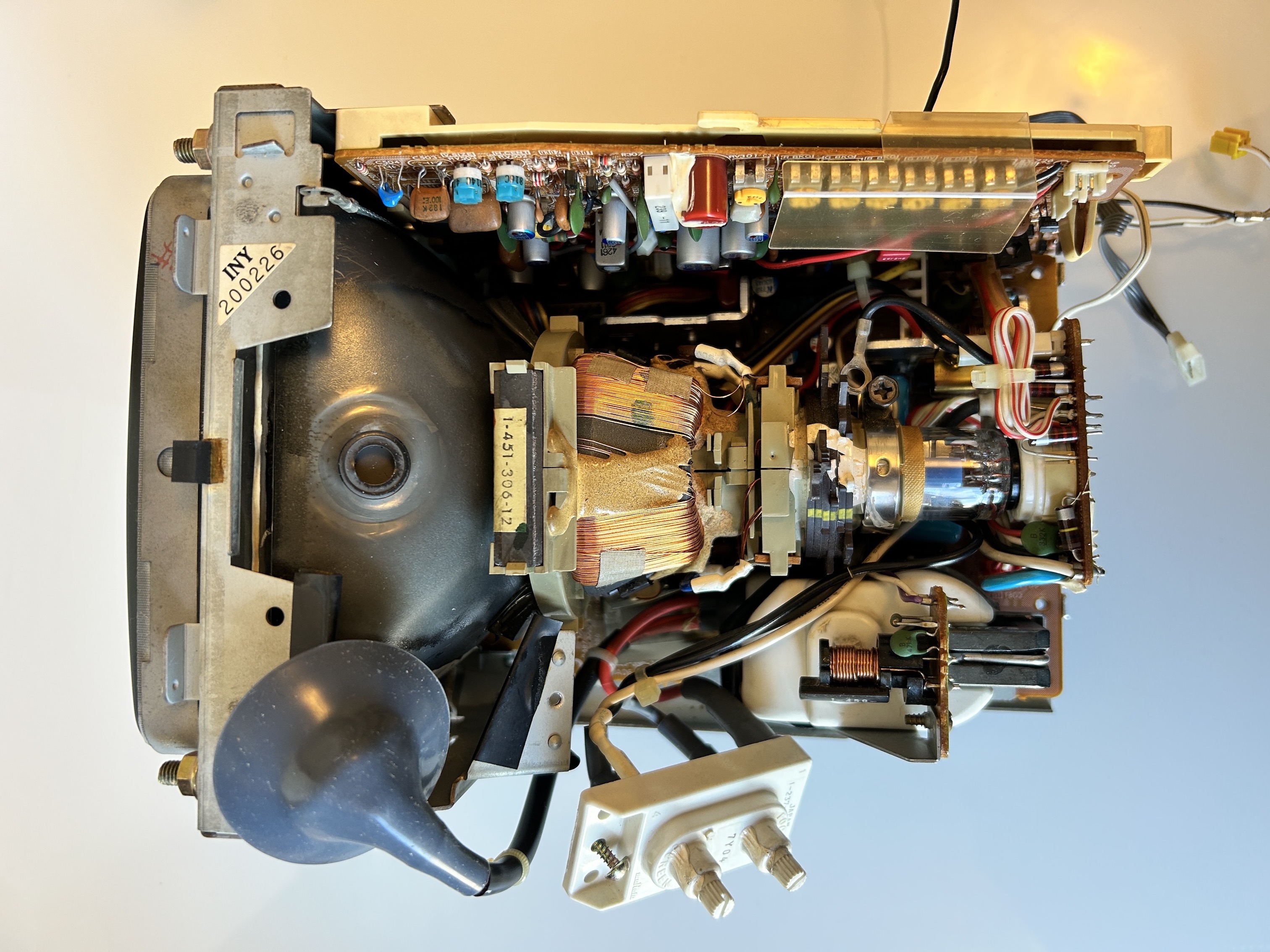
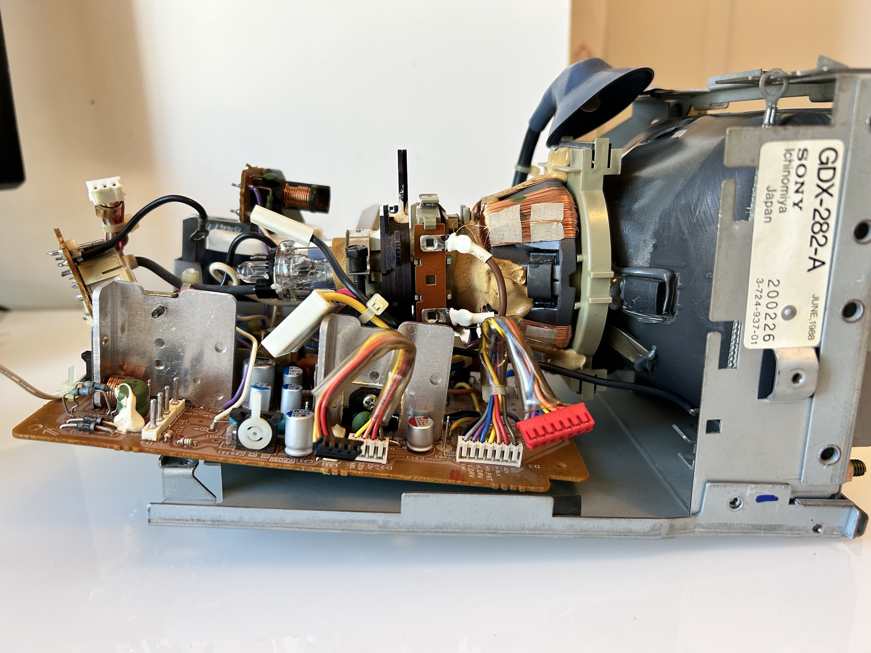
Tube separated out.
Deflection board, Before recapping. 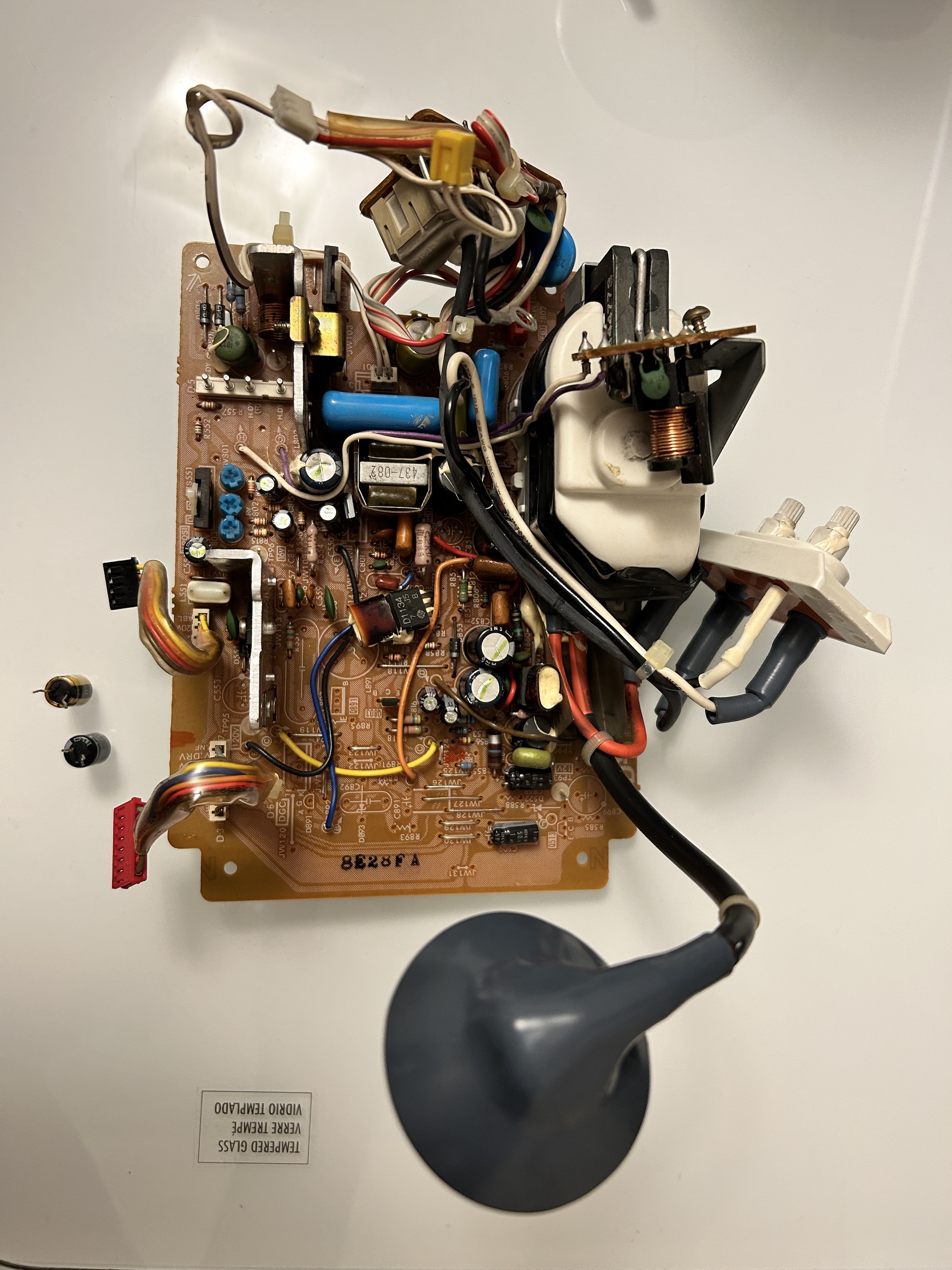
There was a 47uF, 50V capacitor that was completely dried out. 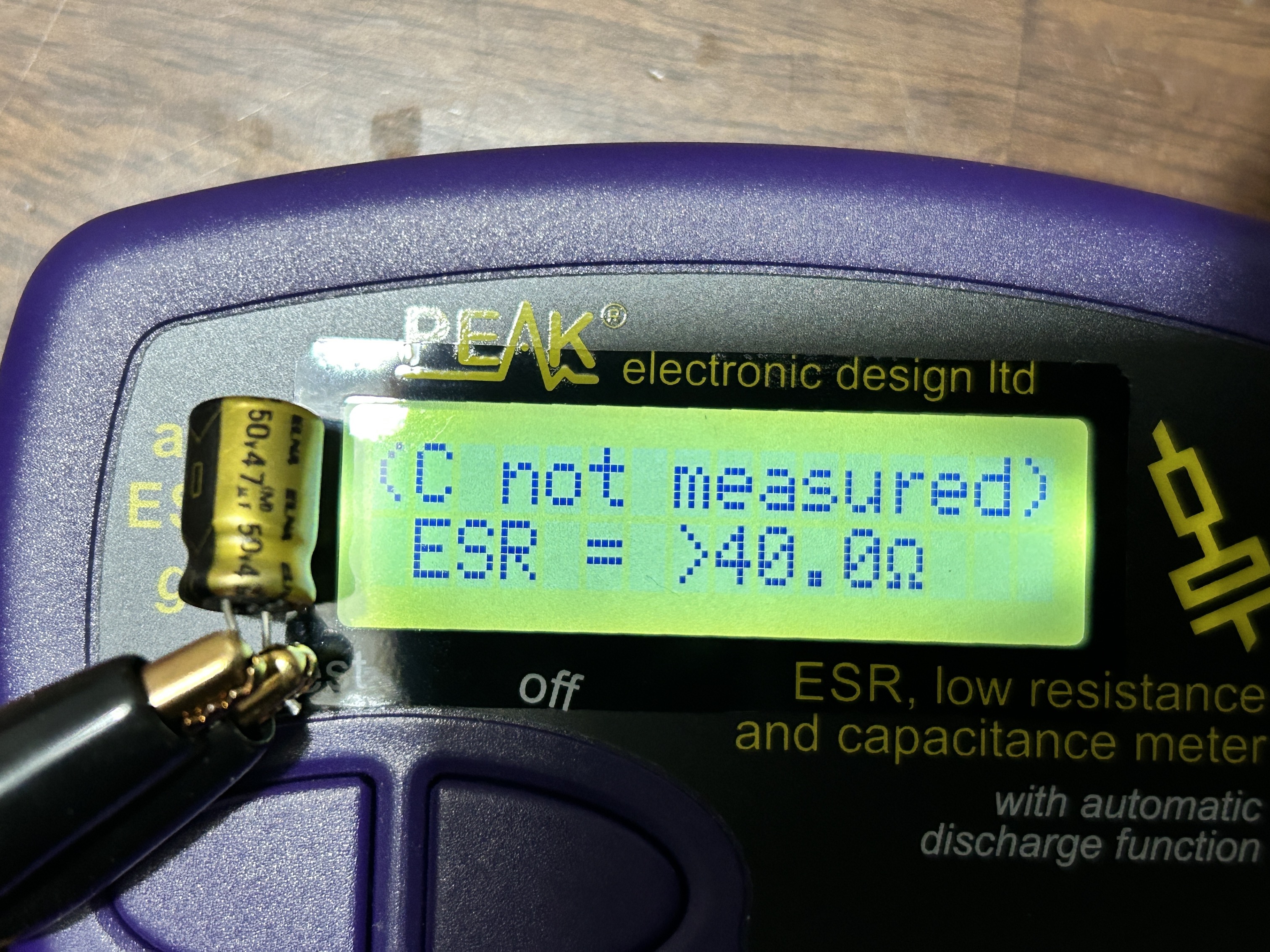
Replaced with solid polymer caps 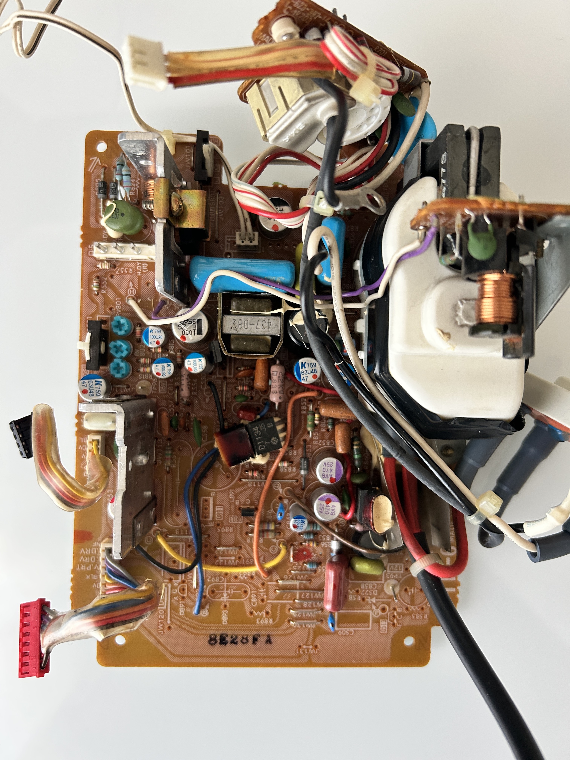
Entire board at the bottom had to be reflowed. There were noticeable cracks in solder joints in several places 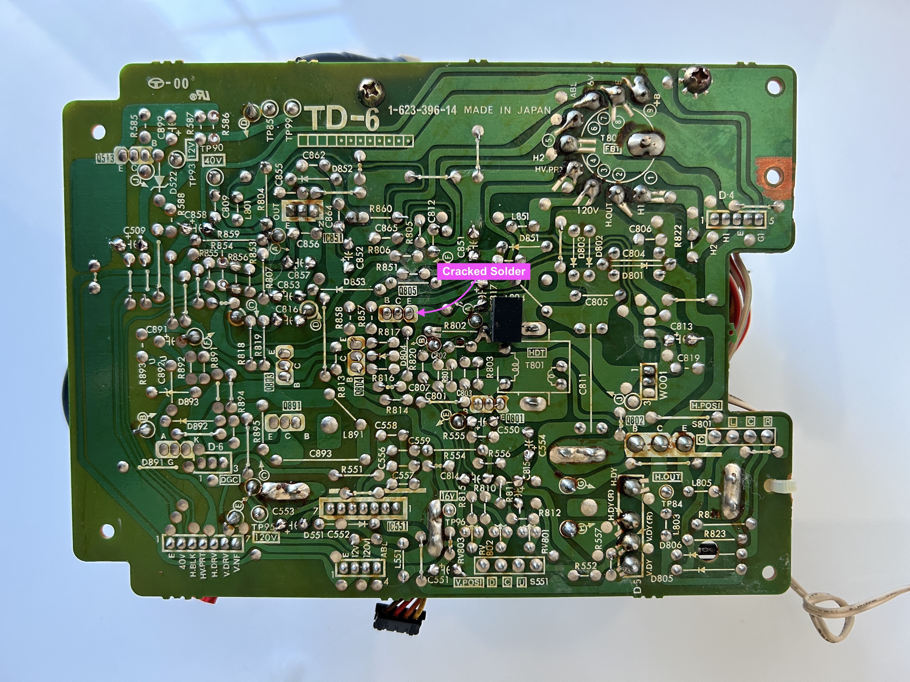
Deflection board after reflowing the full board 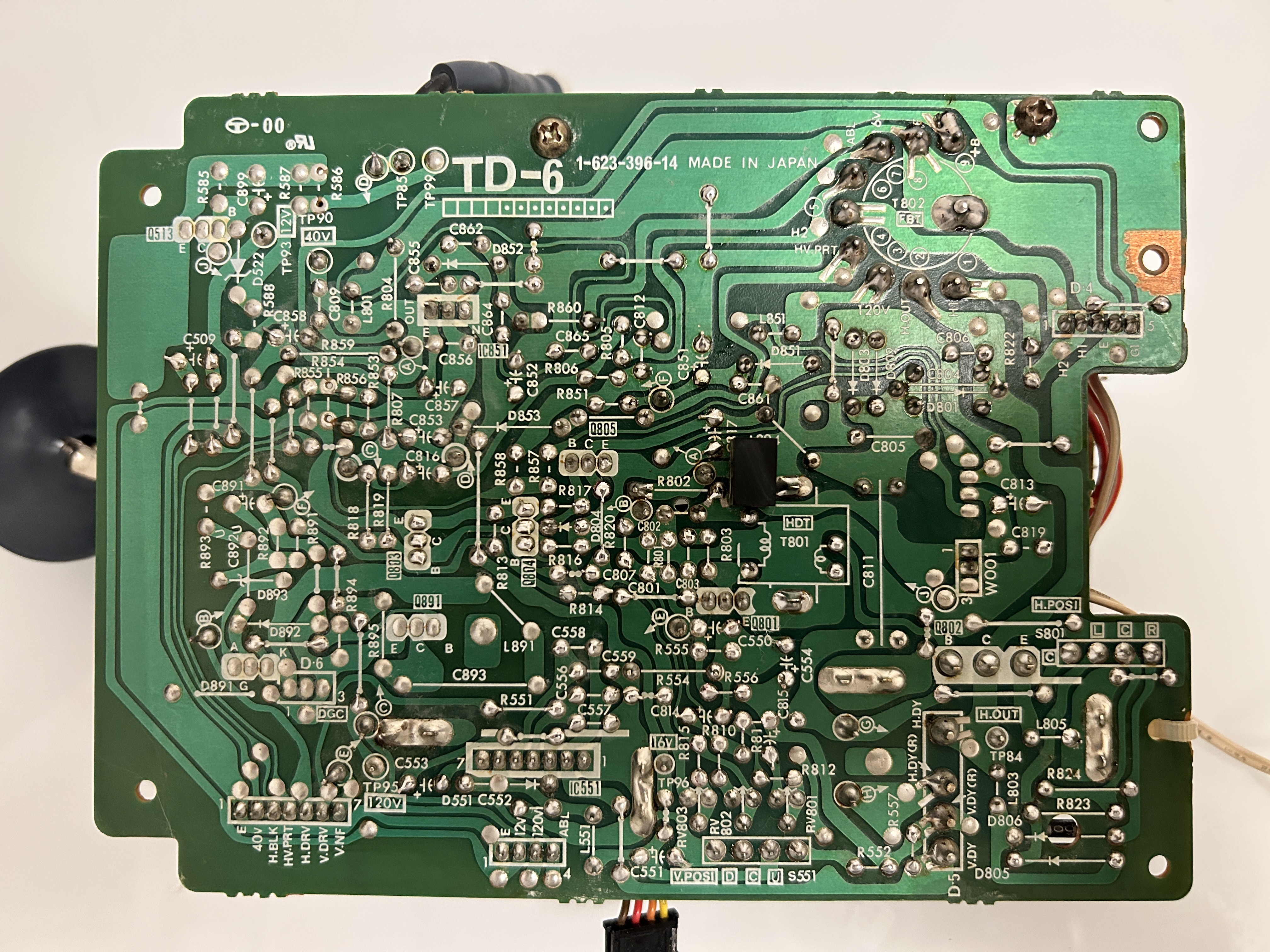
Final deflection board with solid capacitors. 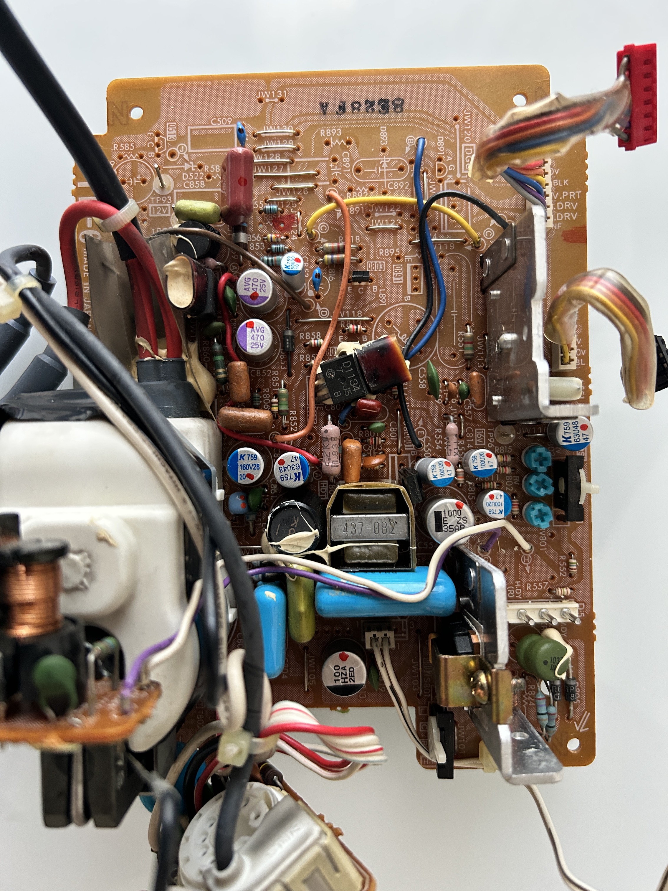
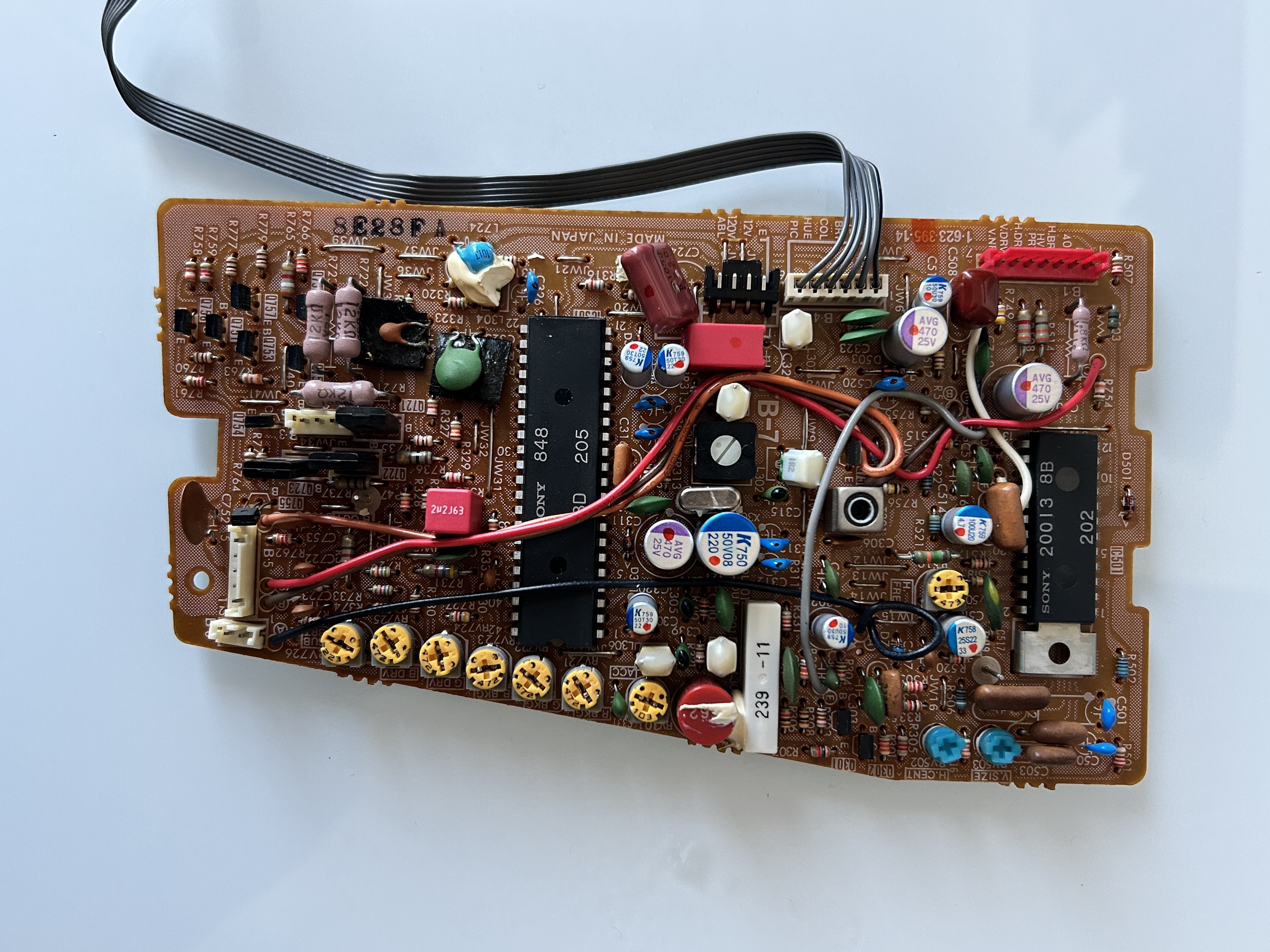
Video board (TB-7)
While most capacitors were ok, several caps on this board also degraded in-terms of capacitance and ESR. While not entirely needed, I also decided to change the capacitors on this board as well.
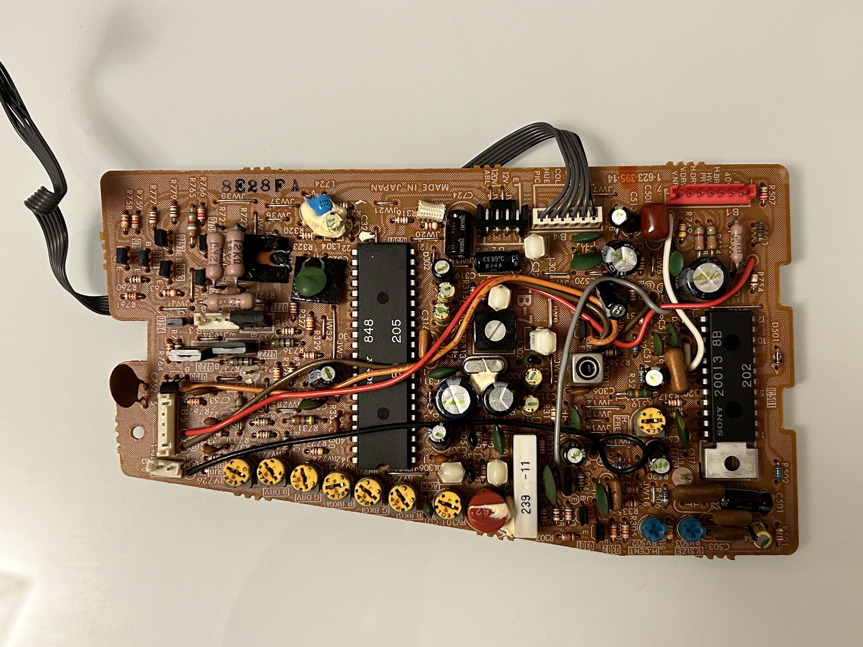
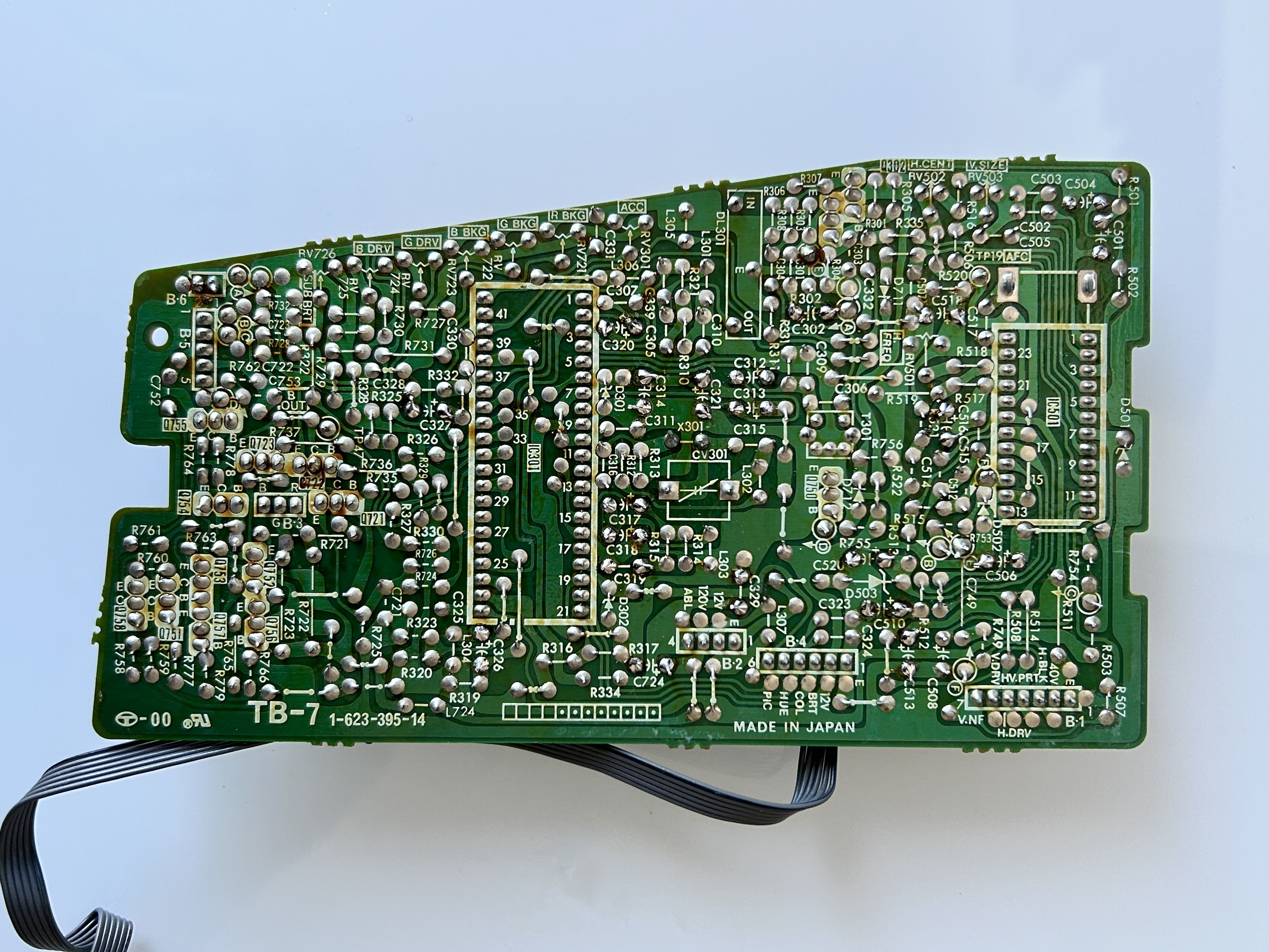
After reflowing and changing to solid capacitors.
Neck board (TC-6)
Neck board also had several solder joint cracks, so this board was also completely reflowed.
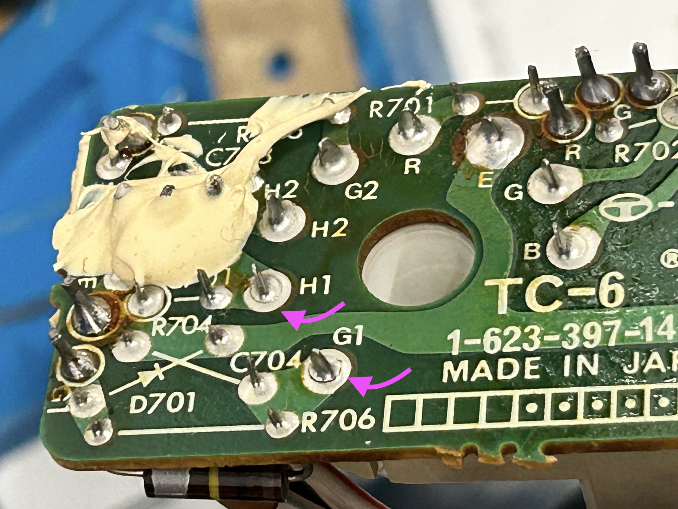
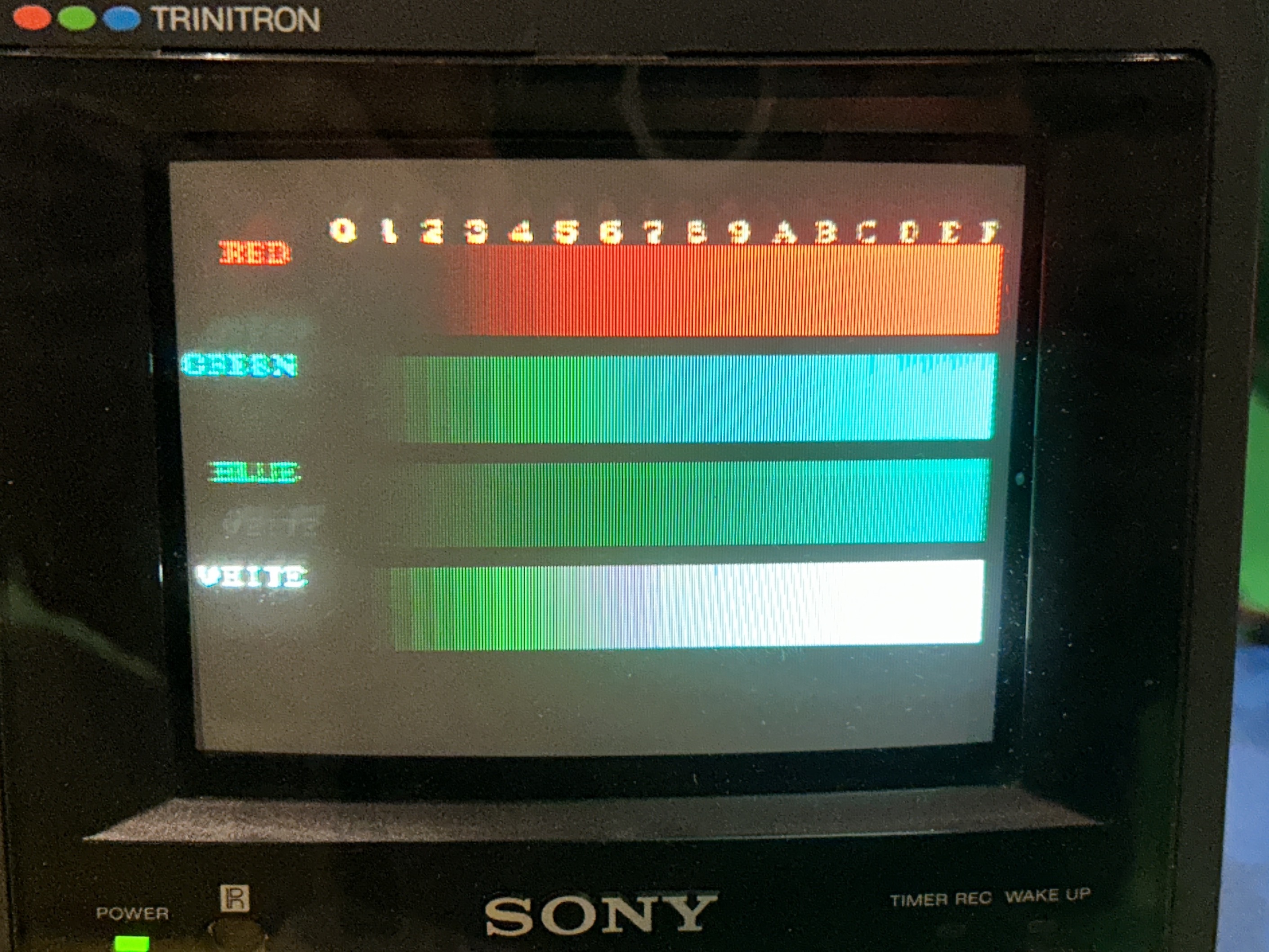
During reflow I accidentally shorted G and B. This is how the screen looked with that issue.
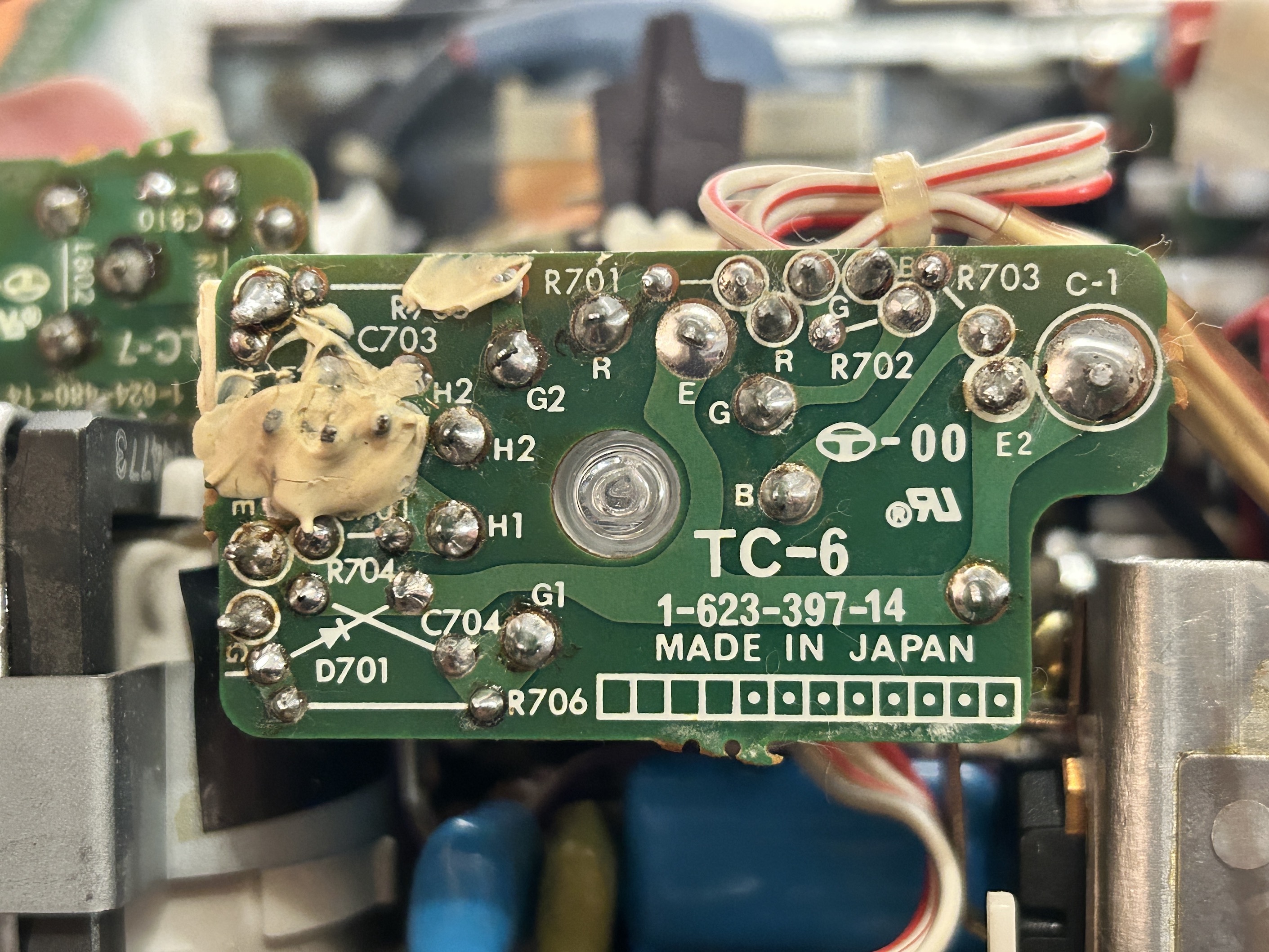
Yet, following a thorough reflow and flux cleaning, the neck board appeared as it was ready for some action.
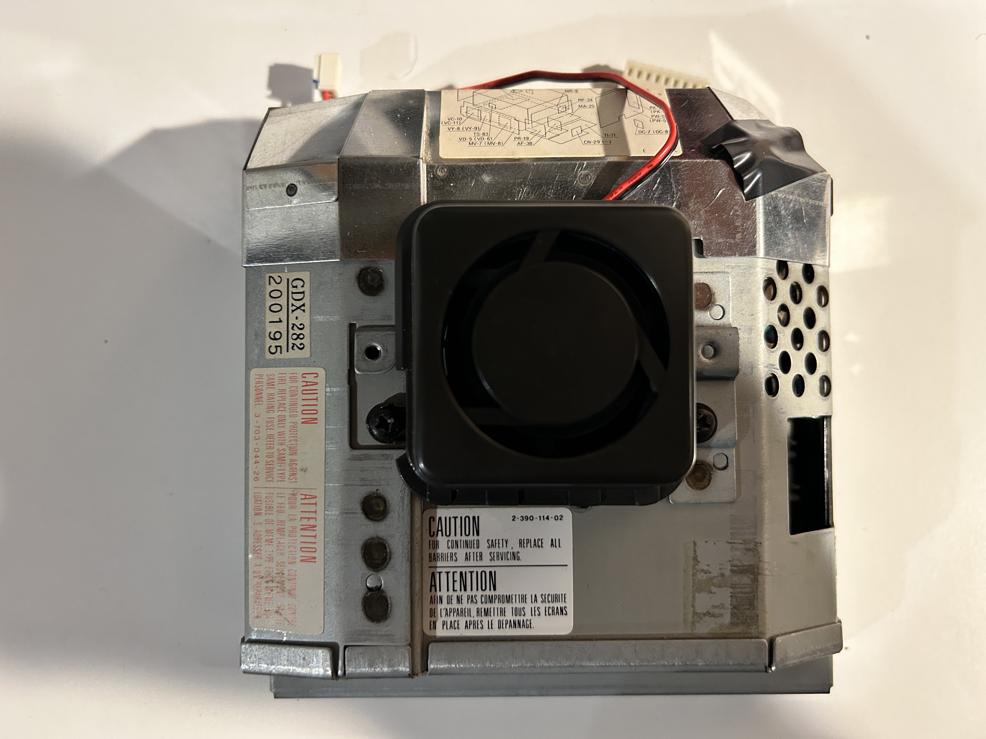
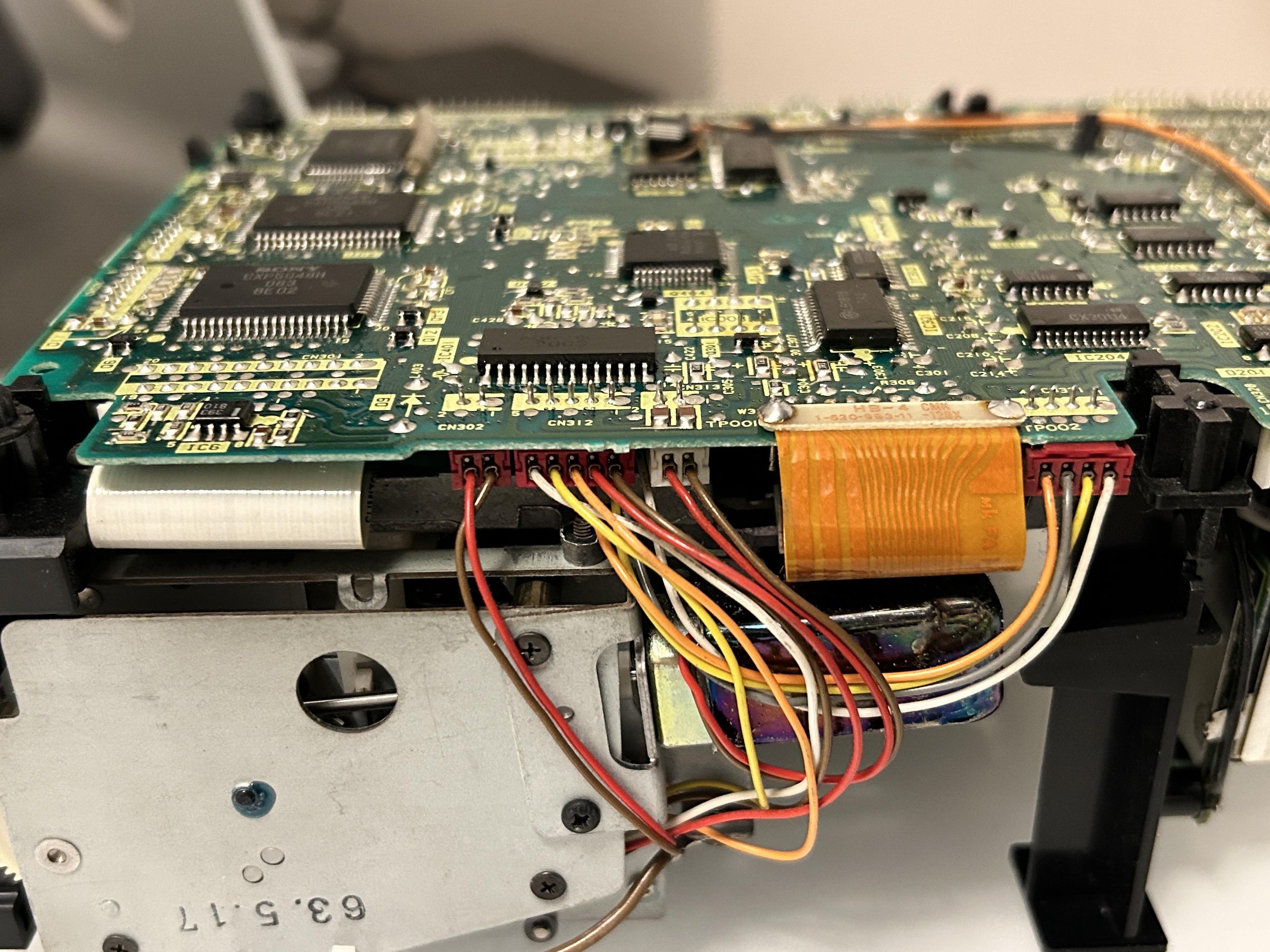
Pictures of the VCR unit
I did not touch anything on this unit as it was functioning well. However, took some pictures.
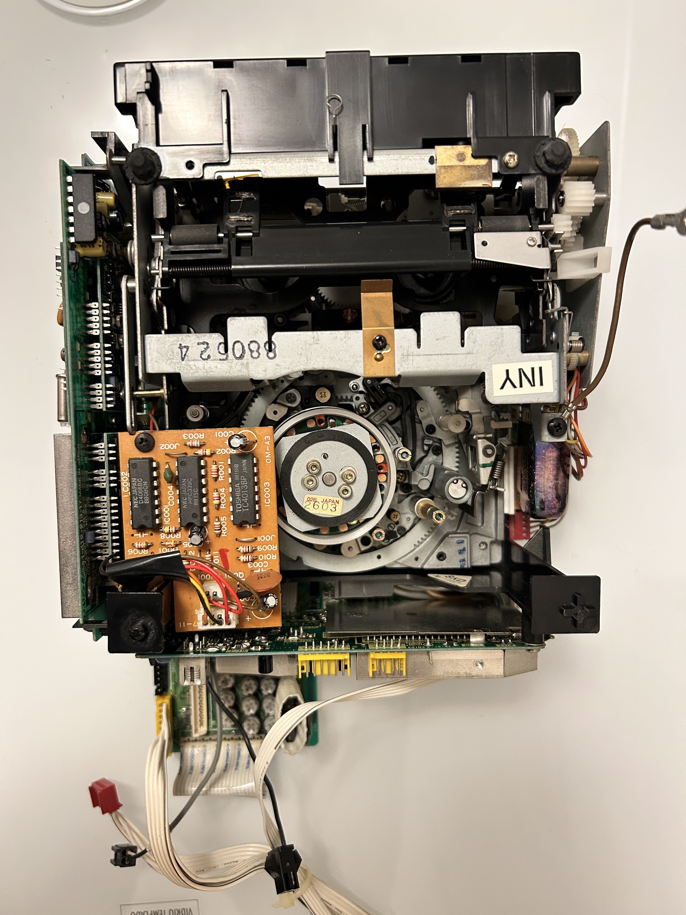
Mechanism 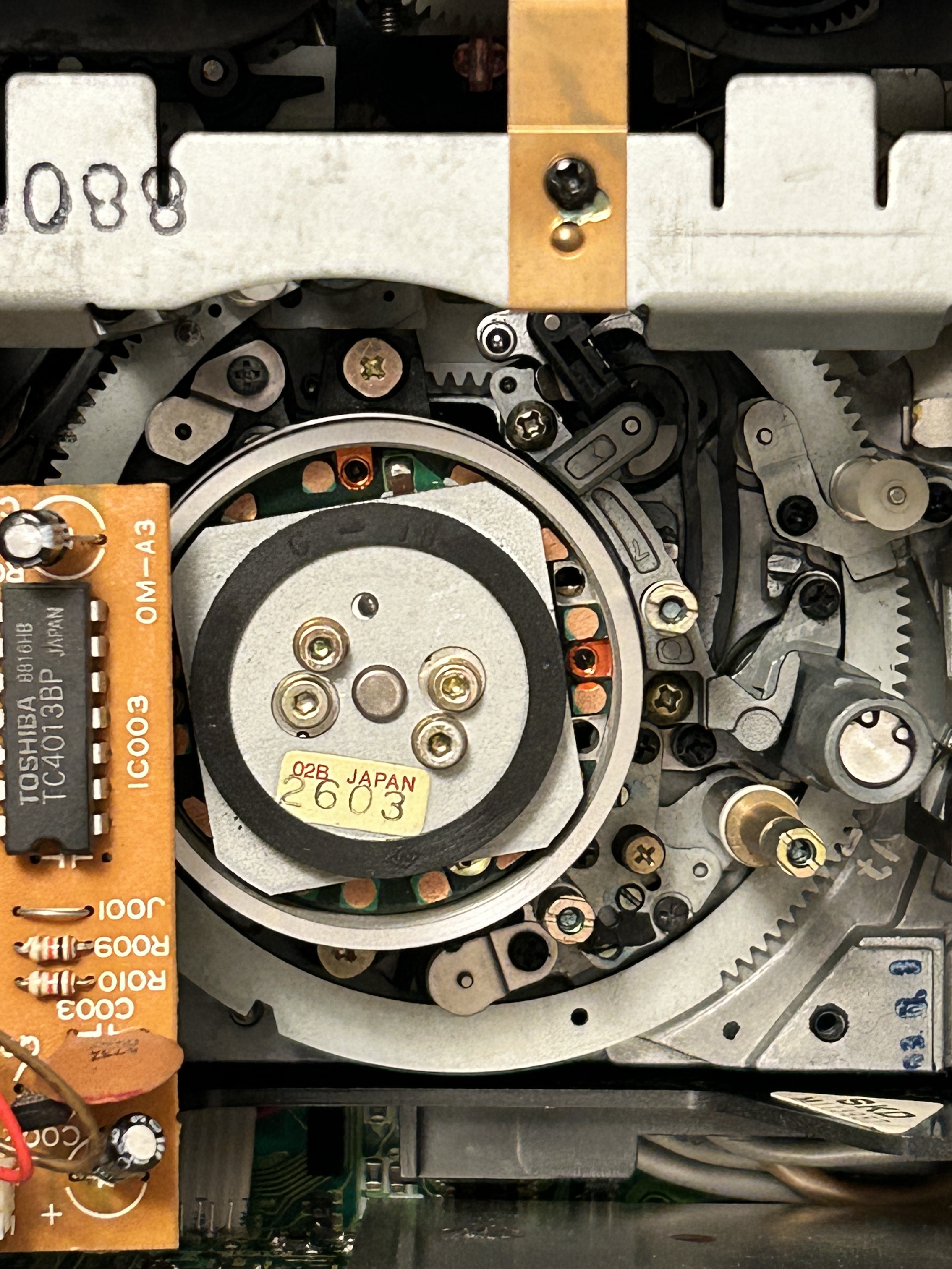
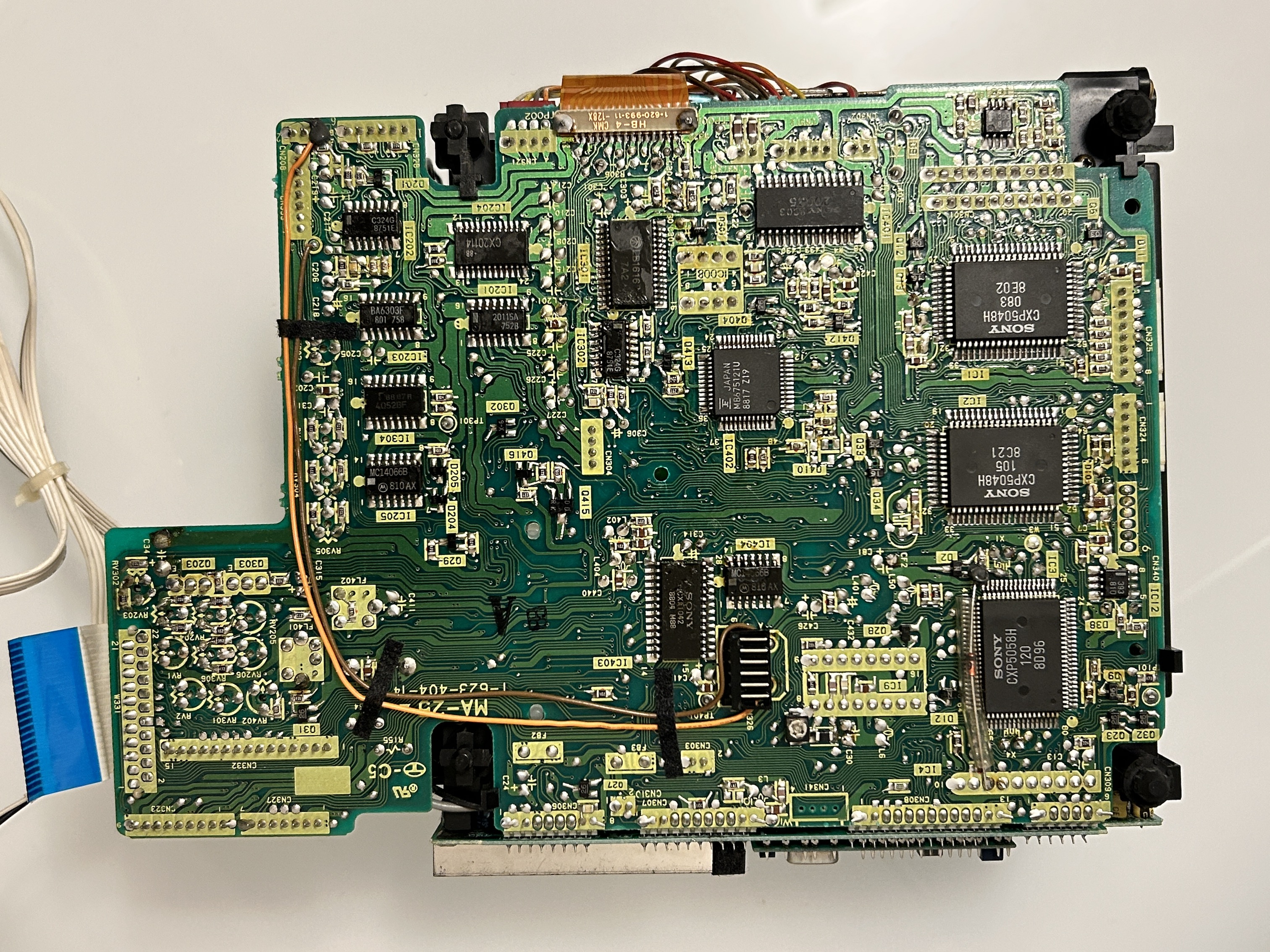
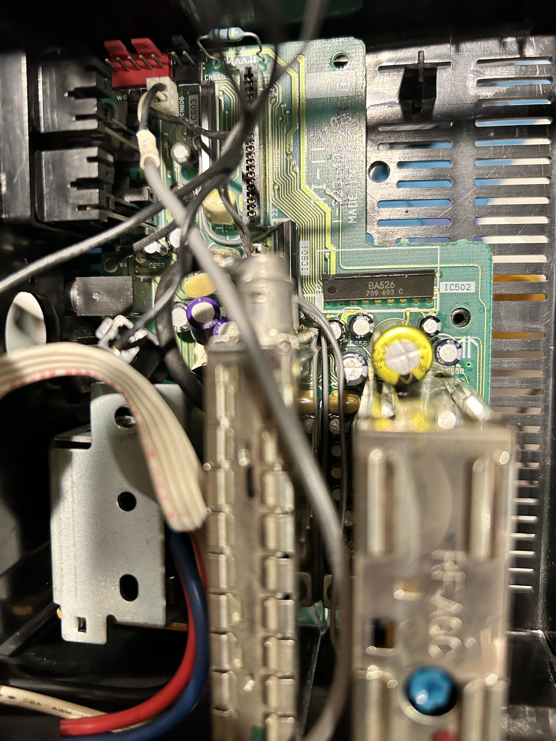
Tuner board
Bottom casing and power connector
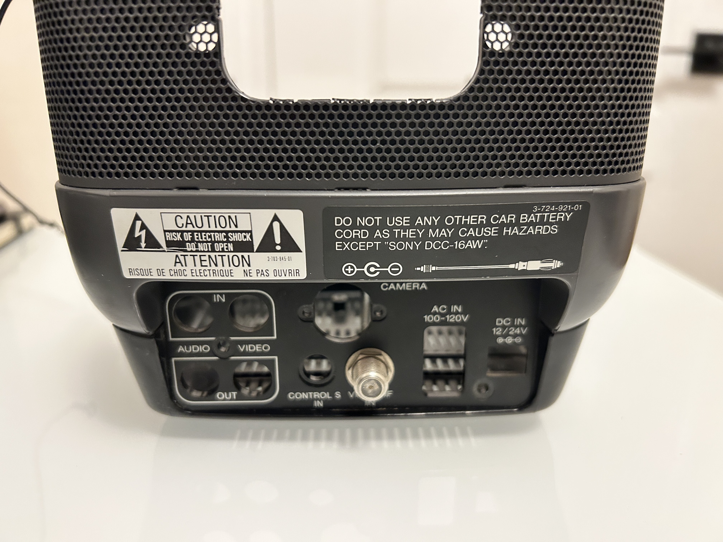
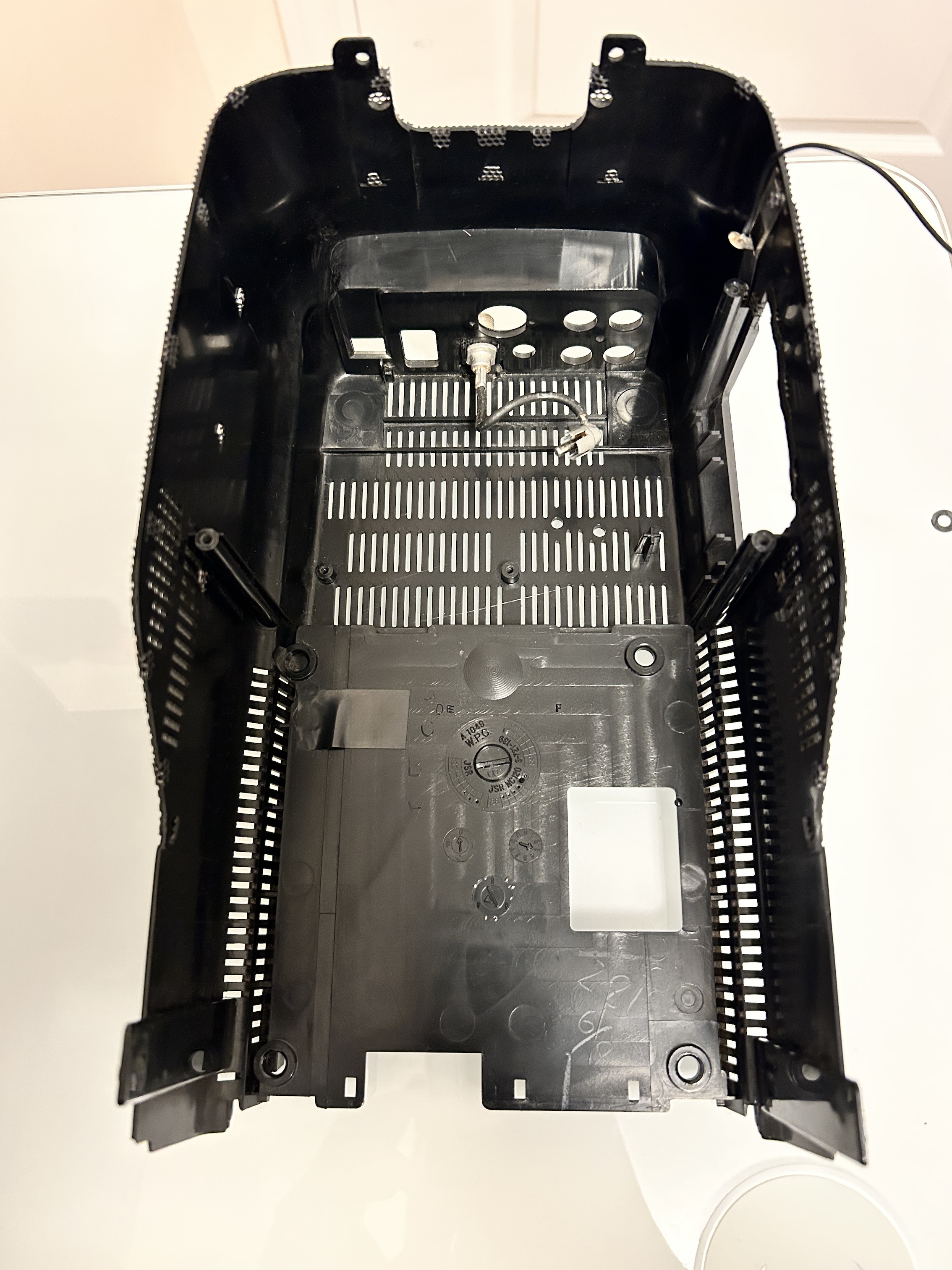
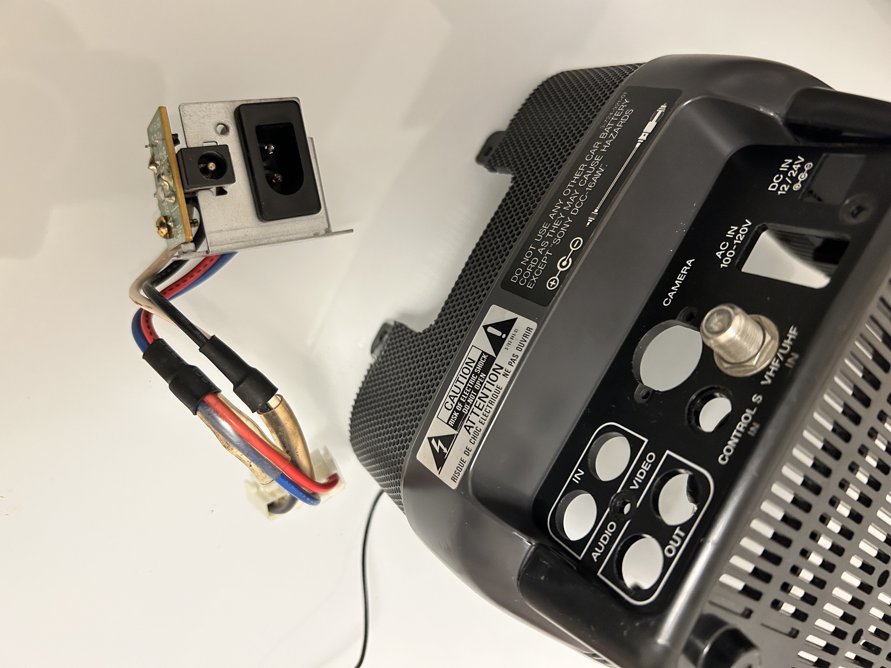
Pictures