Sony FDL-330S (FDM-330)
Sony FDL-330S tear down
In 1988/1989, the FDL 330S color Watchman TV/Monitor with LCD display was introduced. As of this writing, it's almost 33 years since this device has been in existence. I found one of these units in my local marketplace and was lucky to pick it up for $30 CAD. It was a complete set. All I had to do was a bit of cleaning and some minor maintenance to bring it back to life.
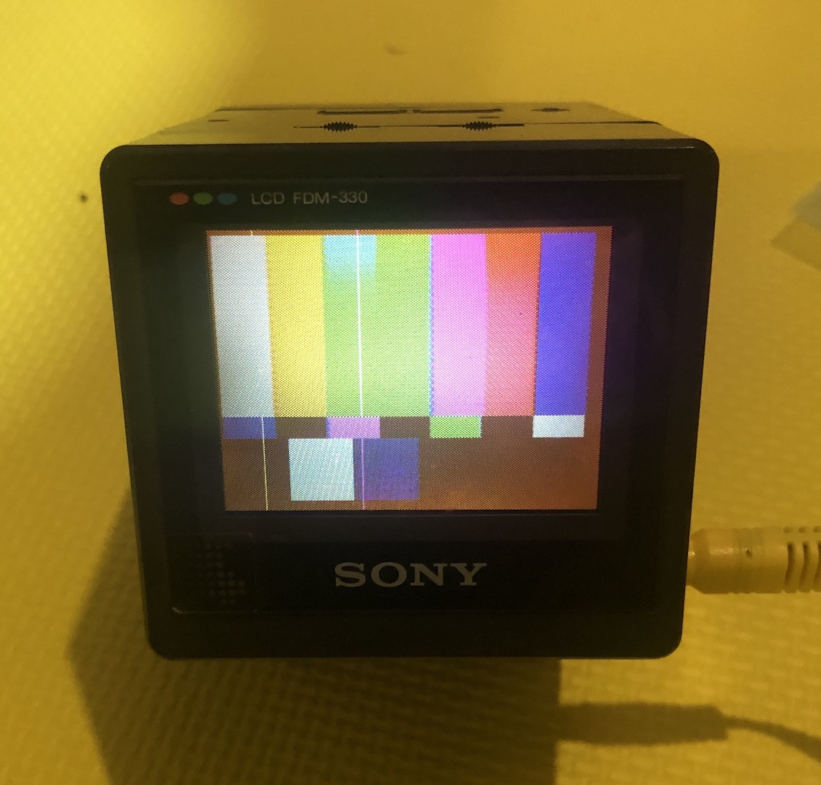
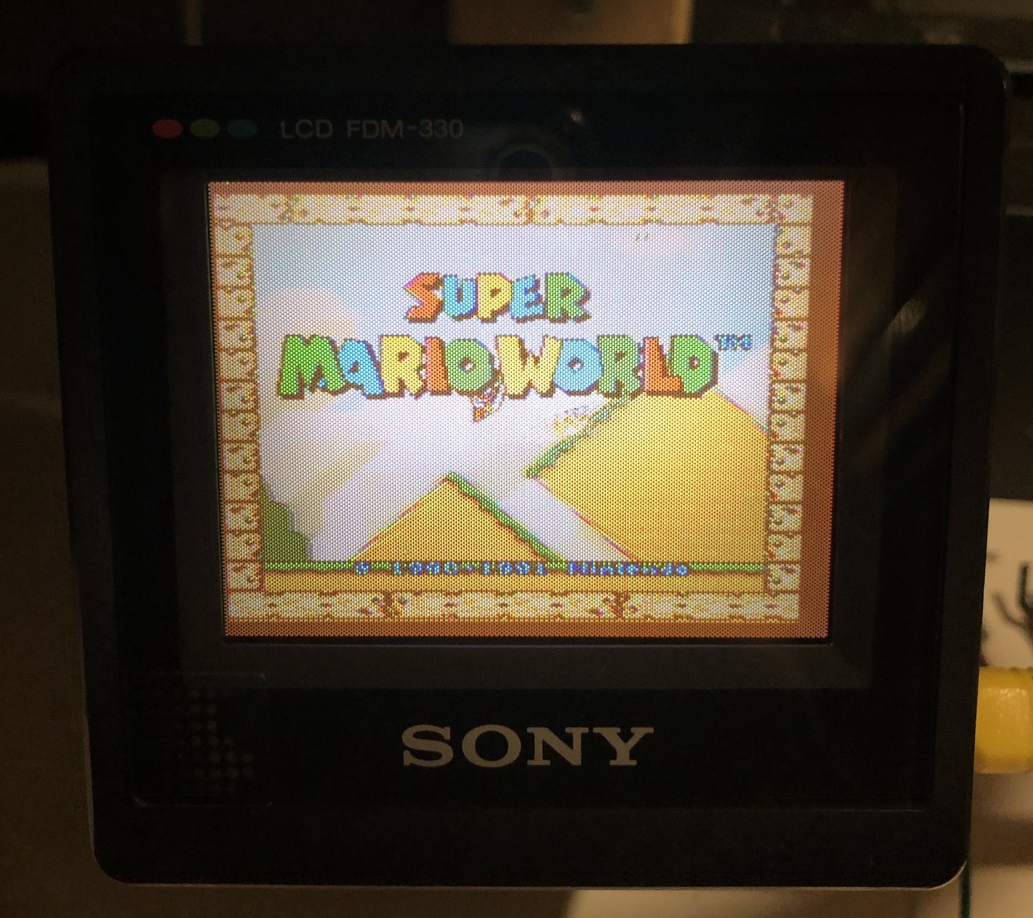
Here is a picture of it working after 33 years. It is really small. The boxy, modular design is something to behold. 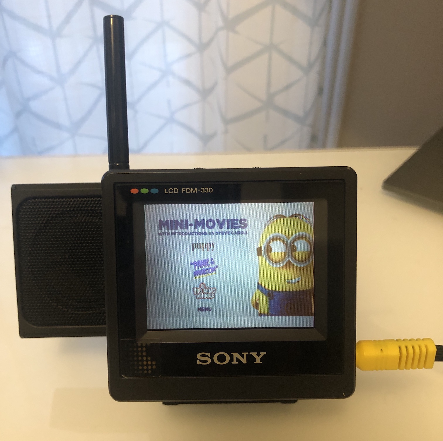
Table of contents
Structure
There were 4 modules in this unit. You had to push the lever on the side to detach the module. I thought it was very cleverly designed.
- Battery
- Tuner
- Speaker
- LCD unit
First try
The battery compartment had some sulfur deposits and corossion. The seller probably didn't scrub it enough, it didn't work for him with new batteries. Therefore he sold the entire package as is. However after taking it apart and cleaning with vinegar and alcohol it just worked without any issues. When I heard the static noise, and some image, I was plesantly surprised. After 33 years, this still continues to function.!
Pictures
Top 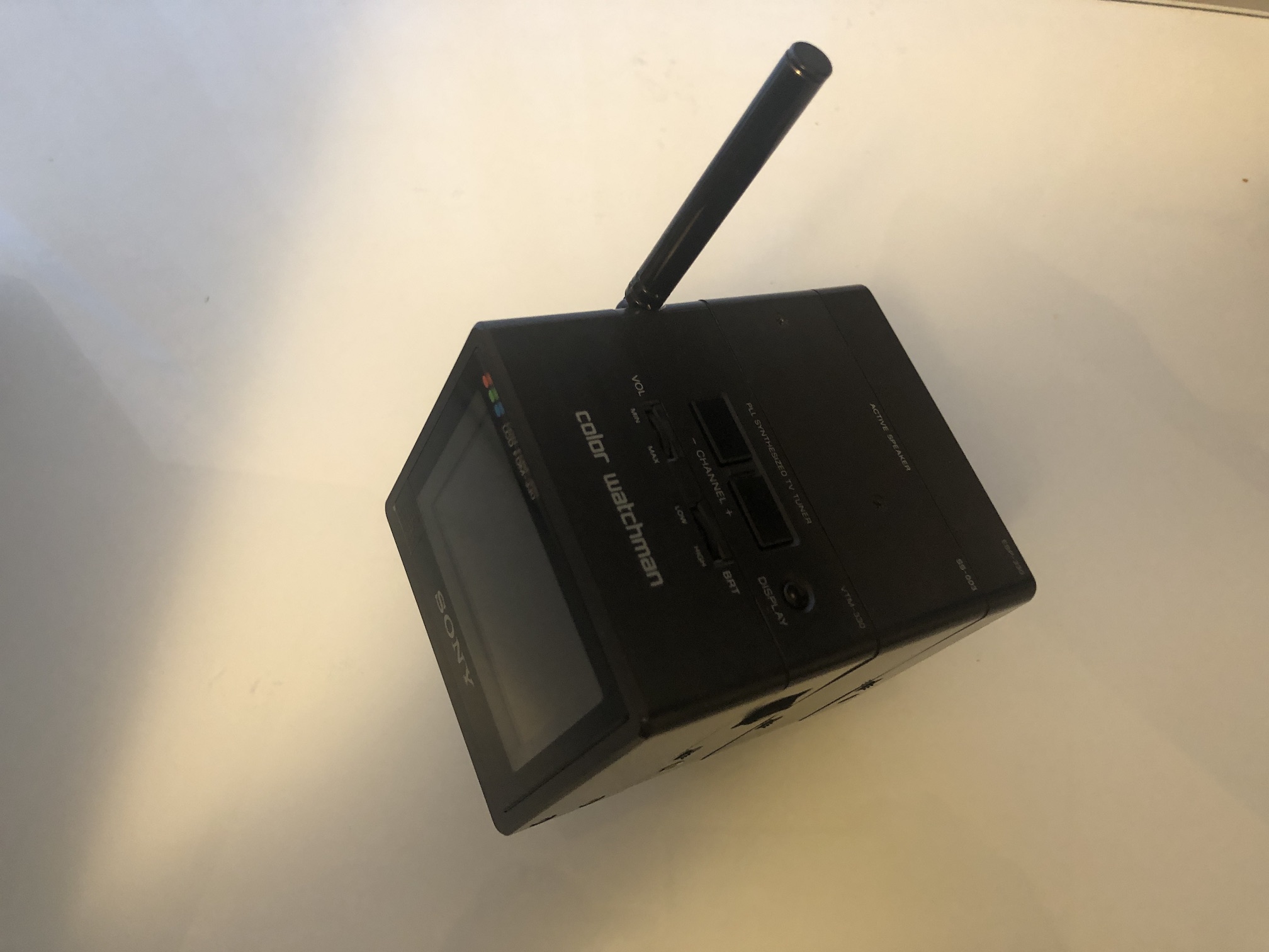
Right 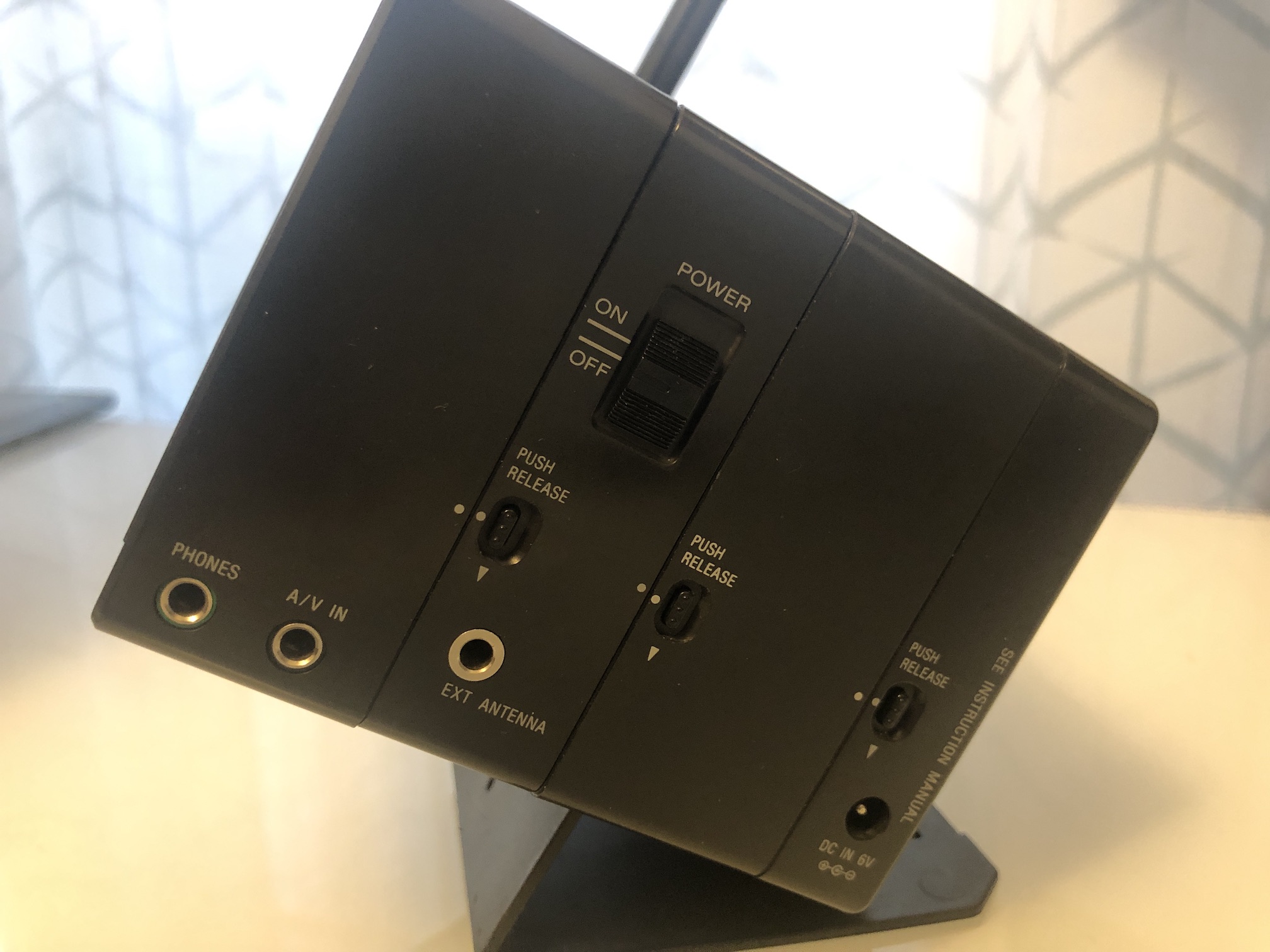
Left 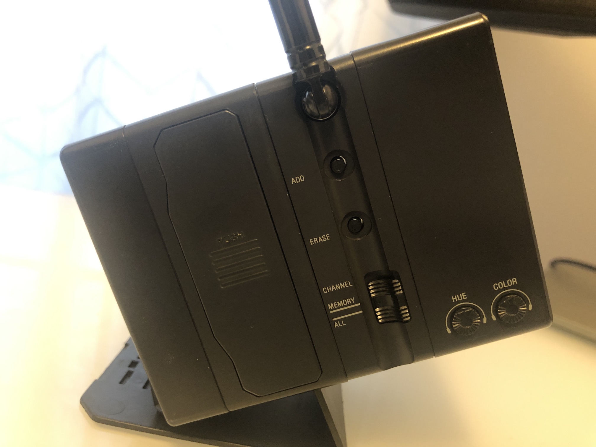
Speaker 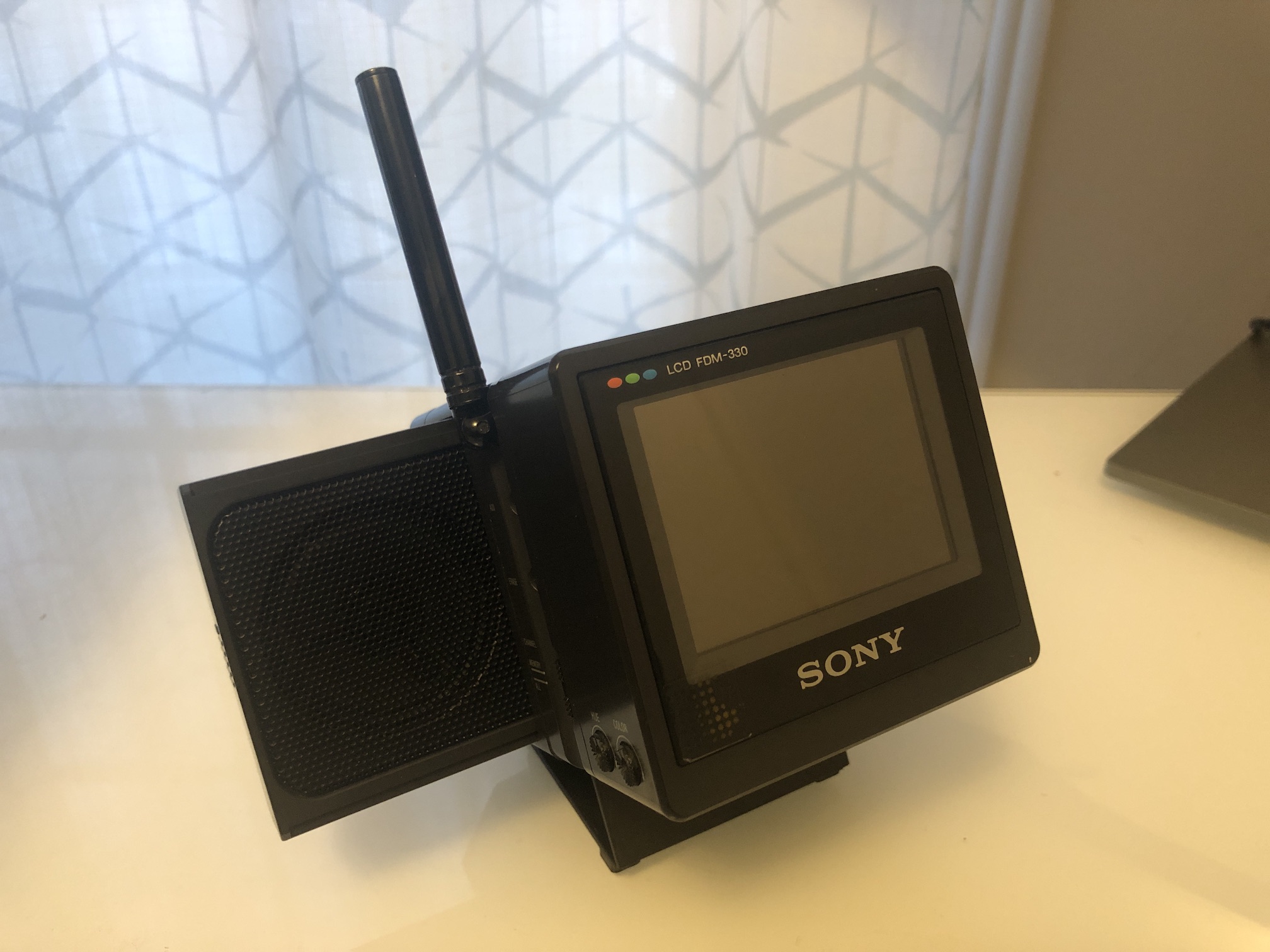
Modules
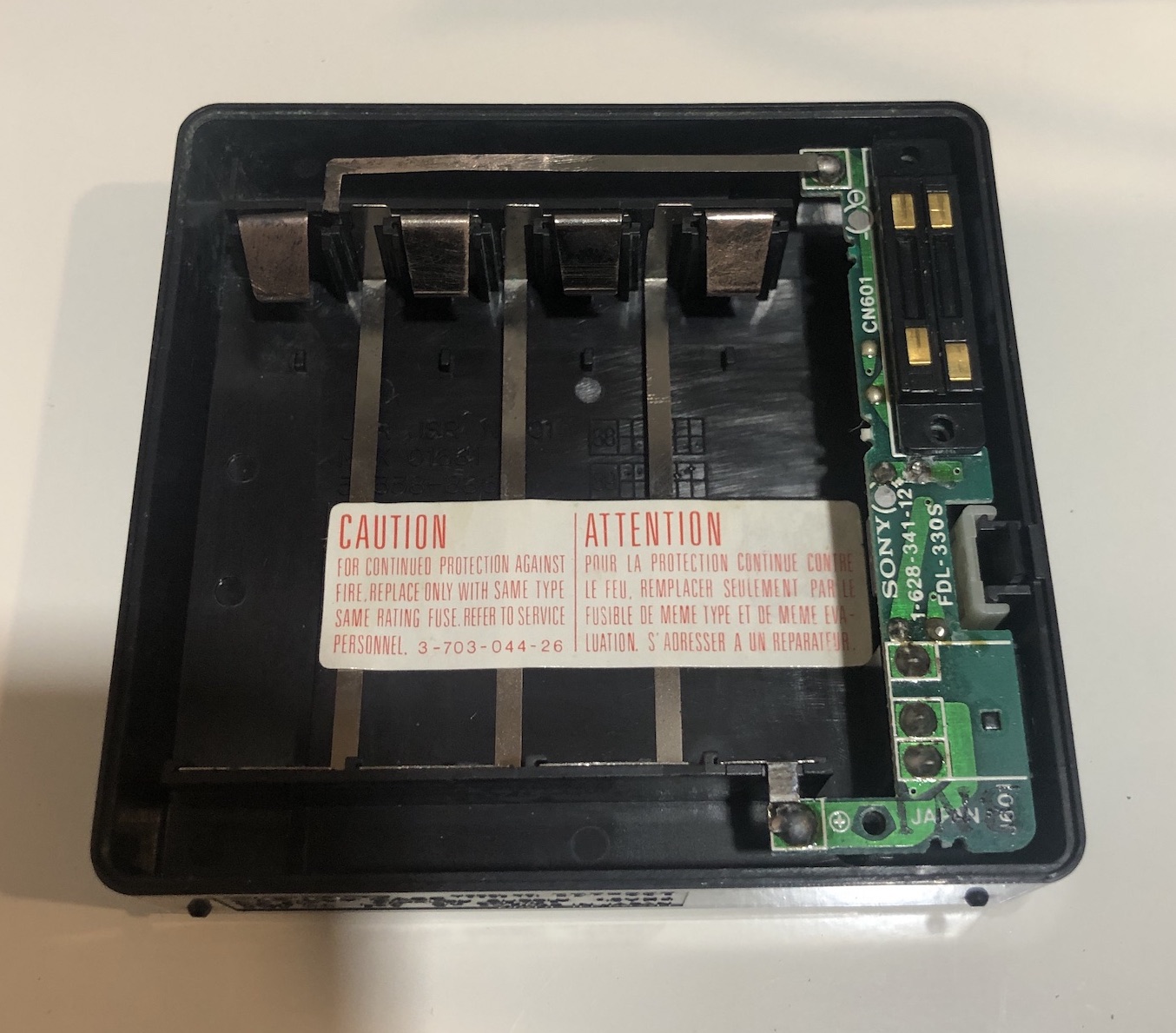
Battery Module
Unfortunately, I didn't take any pictures of the battery compartment before cleaning the corrosion. Here is the picture after cleaning up. It's almost like new.
I also replaced the 10V, 470uF capacitor with 16V, 470uF (105C).
Before changing the capacitor 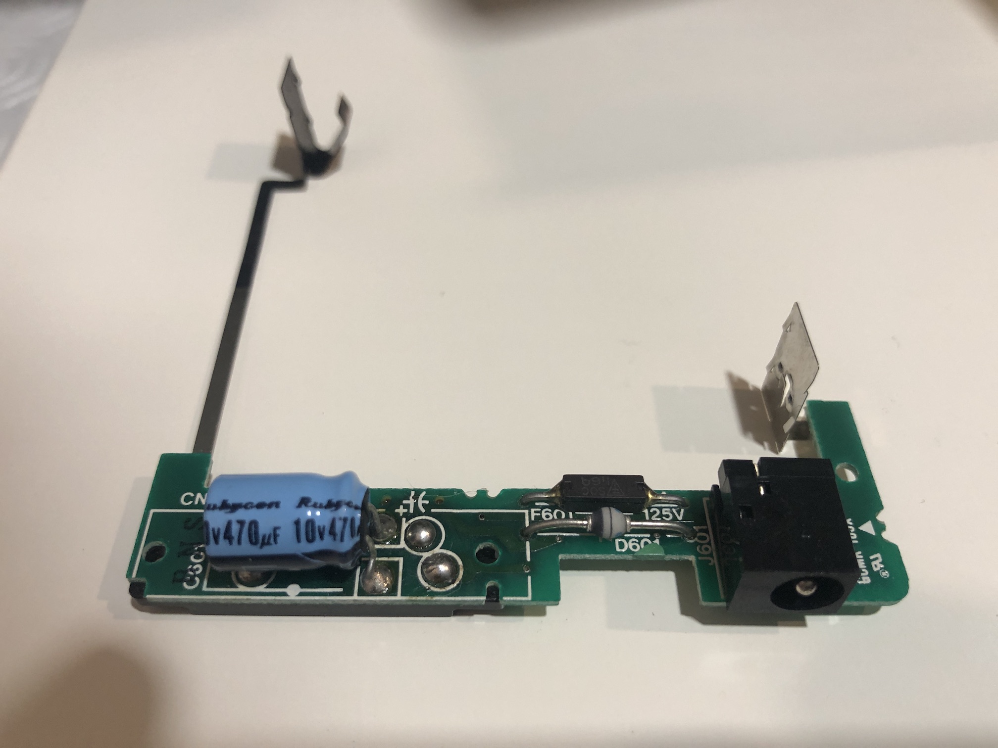
After the capacitor change 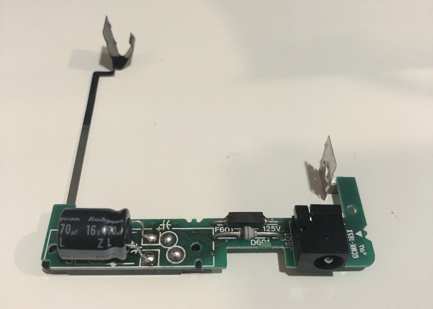
Speaker Module
There was a small board and speaker in there. I opened it up to dust it a bit, otherwise, I didn't want to take it apart further since this module was working perfectly fine.
Tuner Module
When you open the tuner module, this is what you see first. 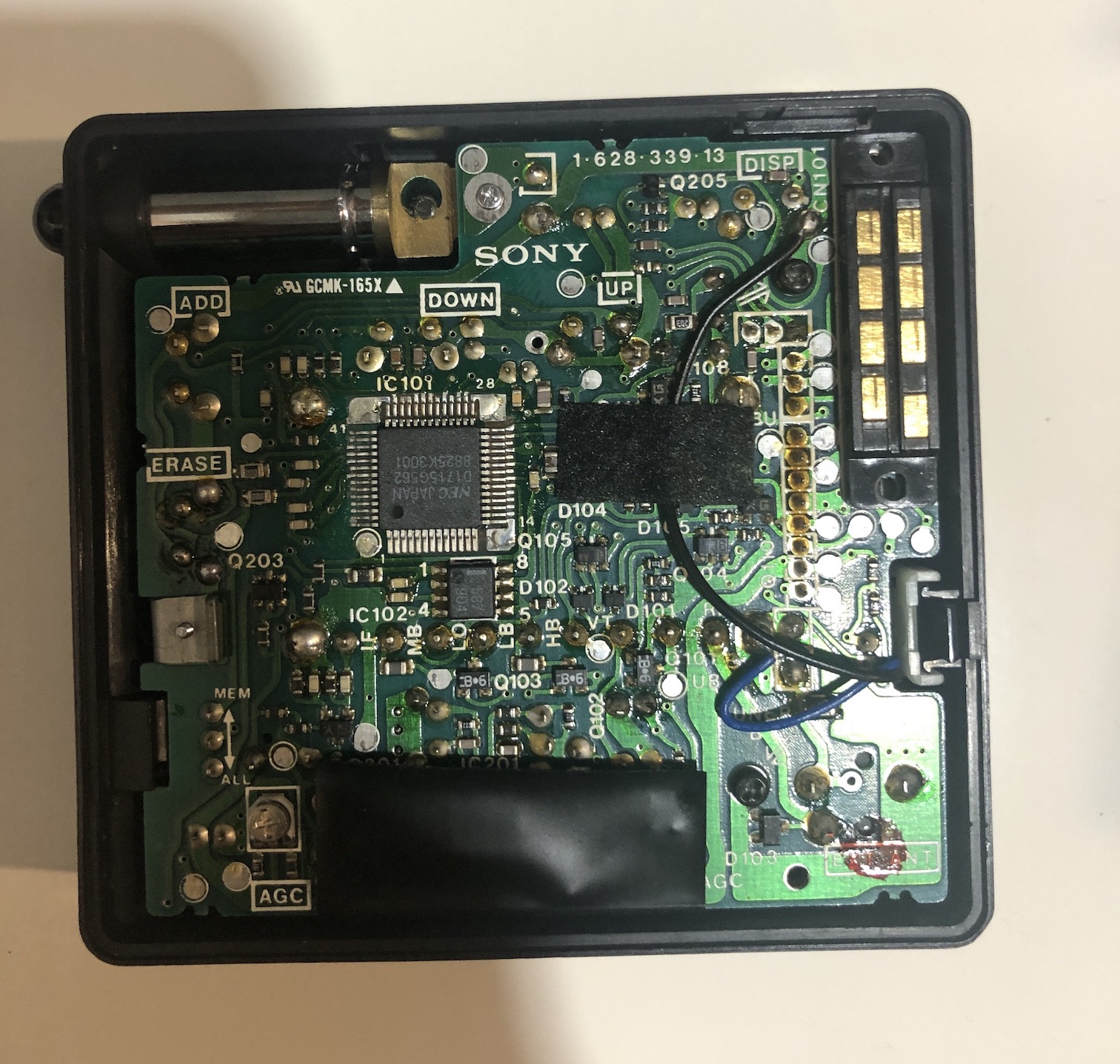
You will be wondering how you are going to get this out as a lot of things are jam packed in here. However, you can with enough patience.
First remove the top board. There are couple of screws holding it down. You have to remove them and wiggle out the board. 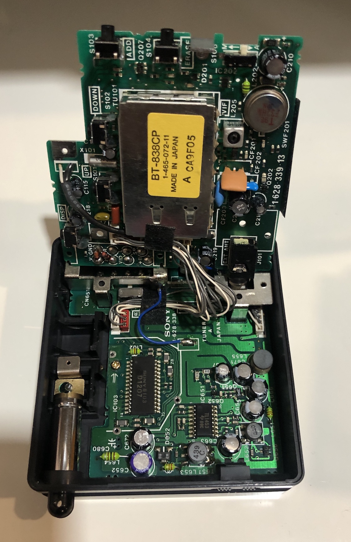
Several electrolytic capacitors were revealed. Fun!
Next remove the bottom board. Pay attention to the screws as there are various kinds. More board pictures below.
Bottom board - Side A 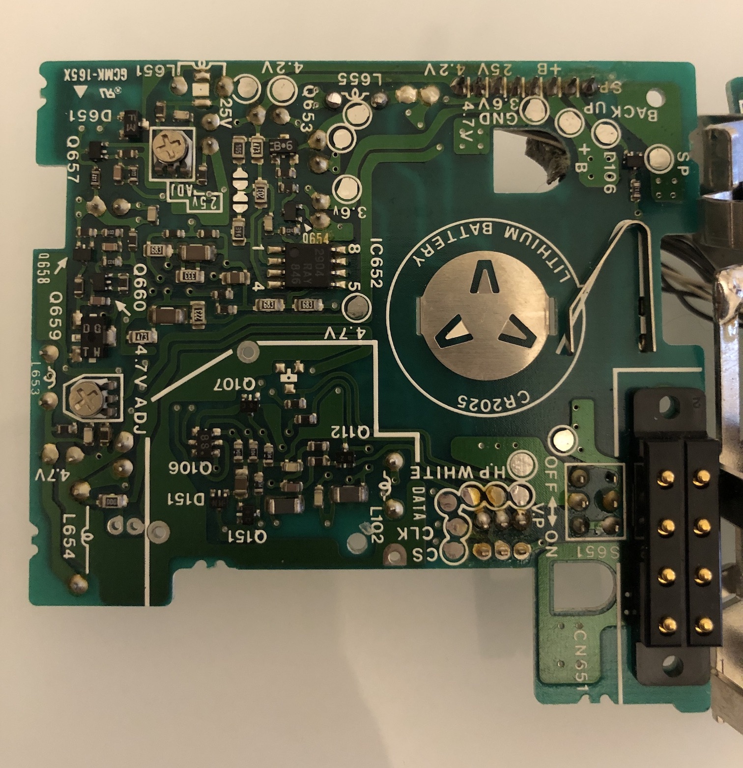
Bottom board - Side B 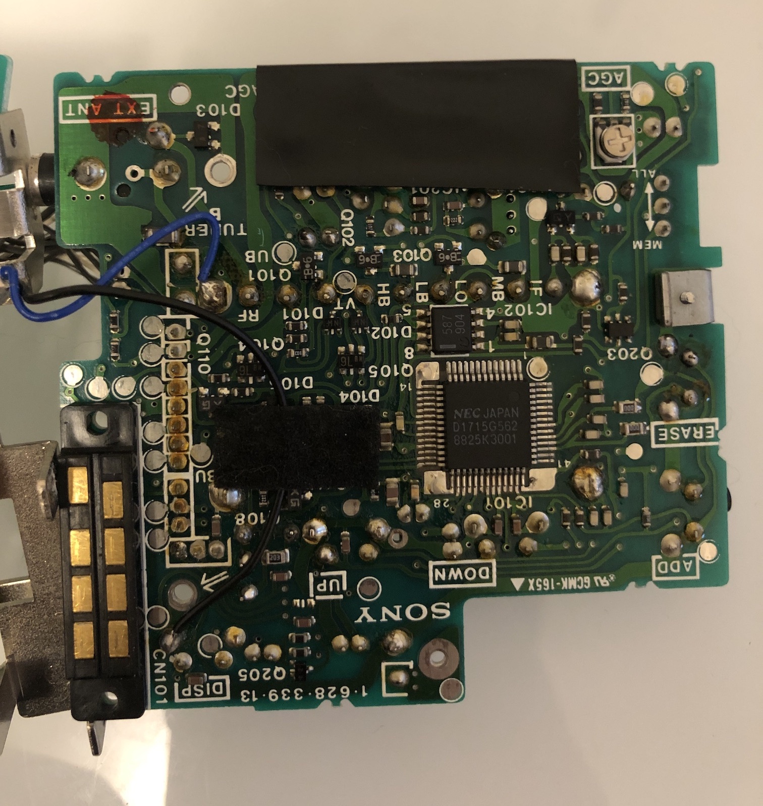
Top board - Side A 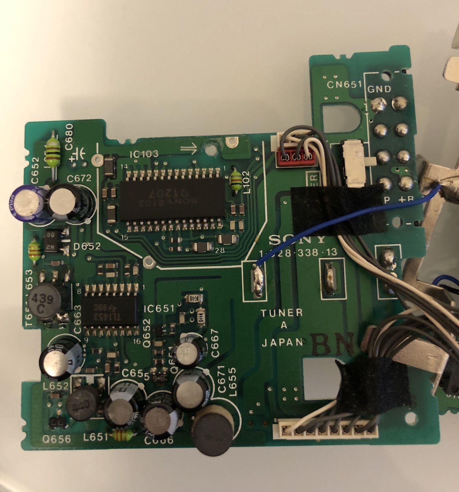
Top board - Side B 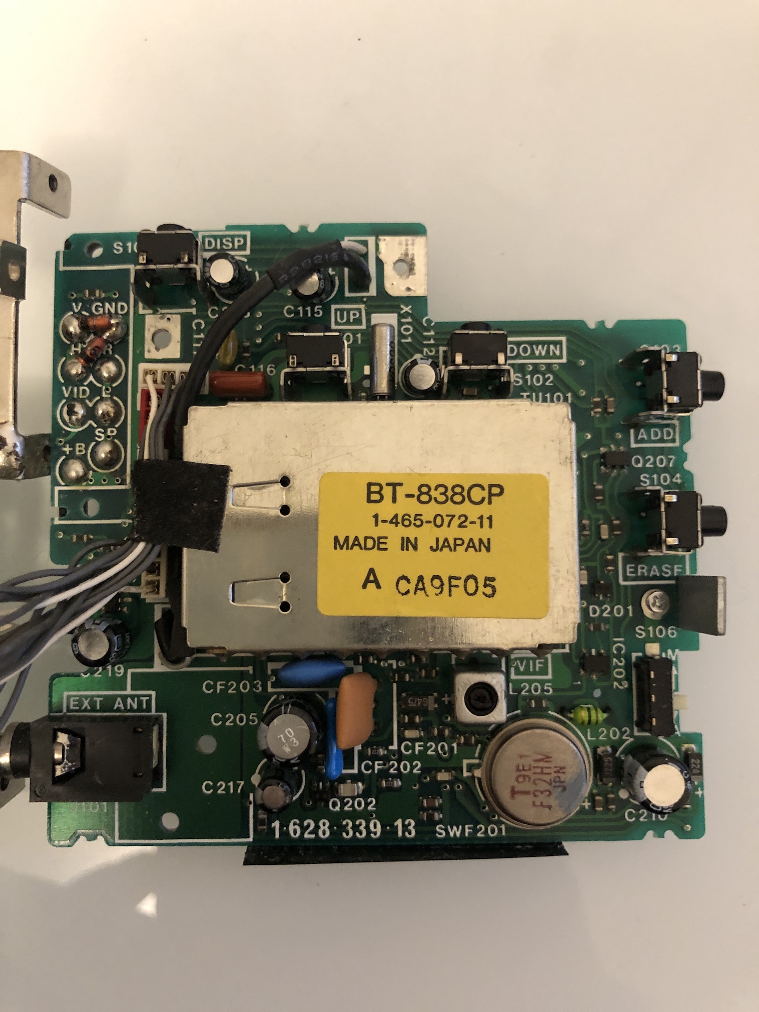
Both tuner boards - Full view 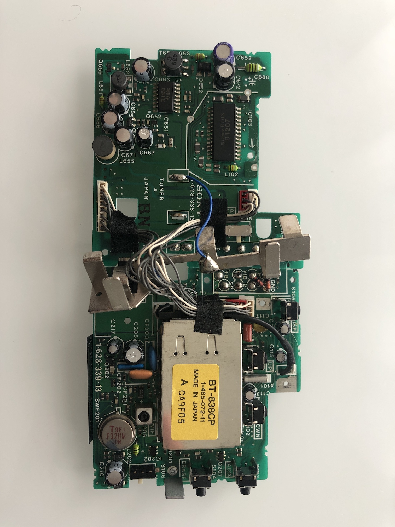
FDM-330 LCD Module
I took a picture of the LCD module before fixing the issue. I noticed two issues.
- There were color issues in the SMPTE color bar test
- There were several lines on the LCD screen.
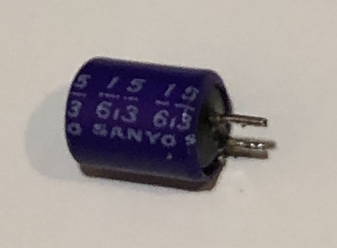
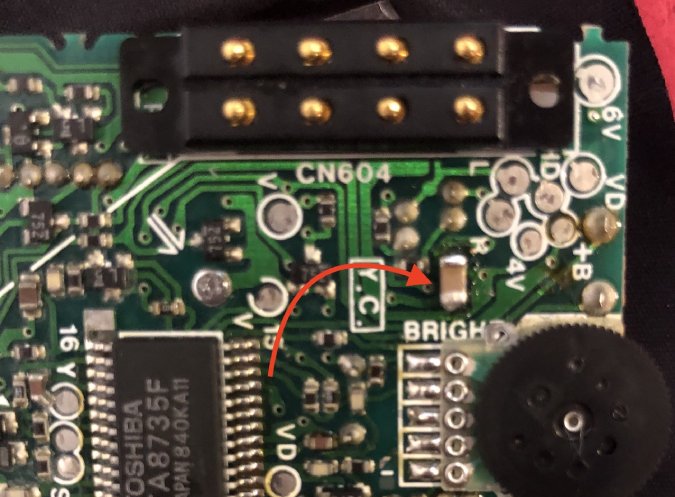
Fix for #1 was to change the below bulged capacitor. I chose to replace it with a 100uF, 6.3V SMD capacitor (C605). I looked at the specs to make sure with DC bias taken into account, it was a good replacement for the bulged 15uF, 6.3V electrolytic capacitor.
Fix for #2 was easy. Just let the LCD run for an hour. Lines fixed themselves. This is because the ribbon cable that was previously detached was now attached back to the LCD with heat.
After fixing both issues, LCD unit looks solid. 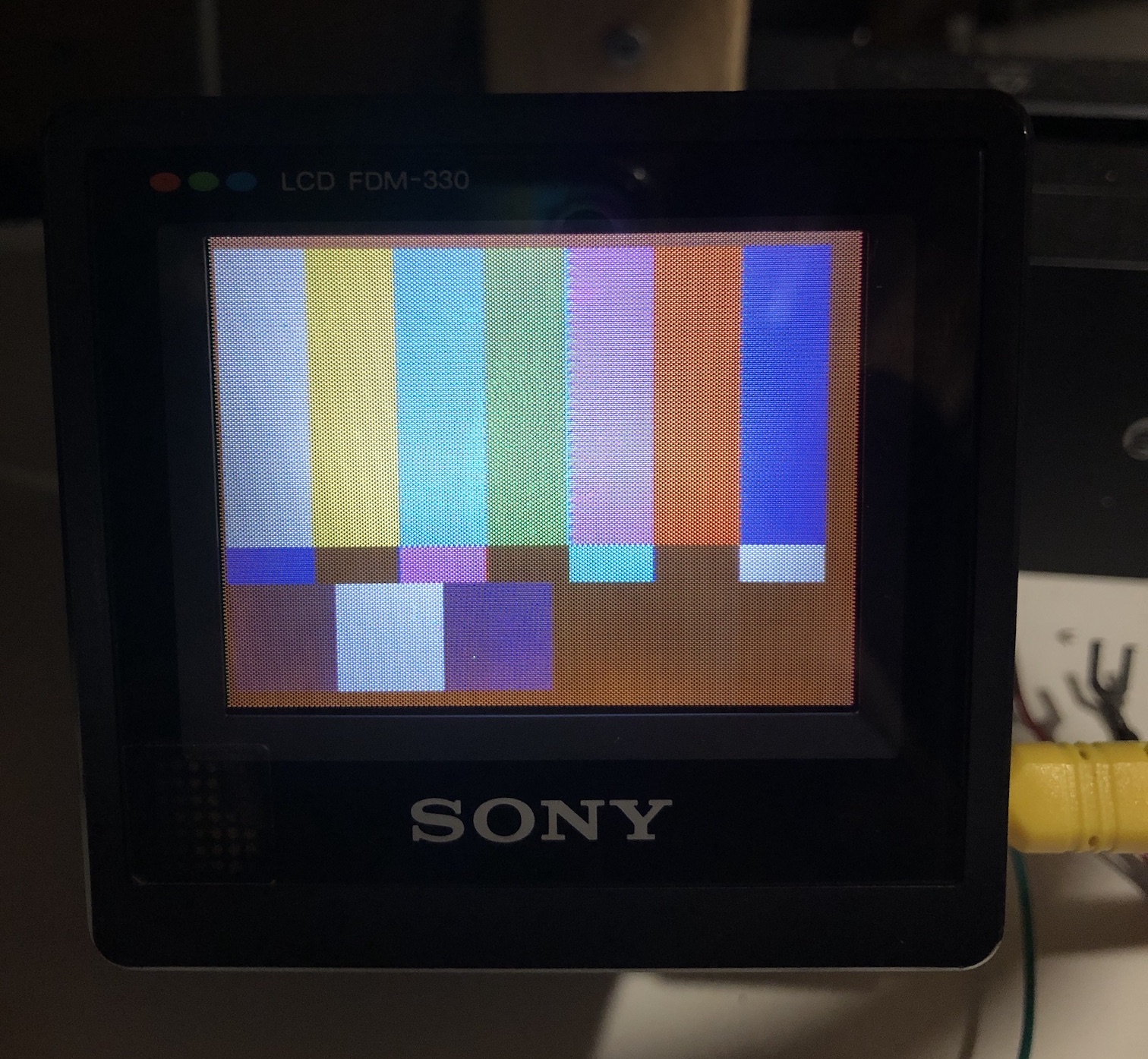
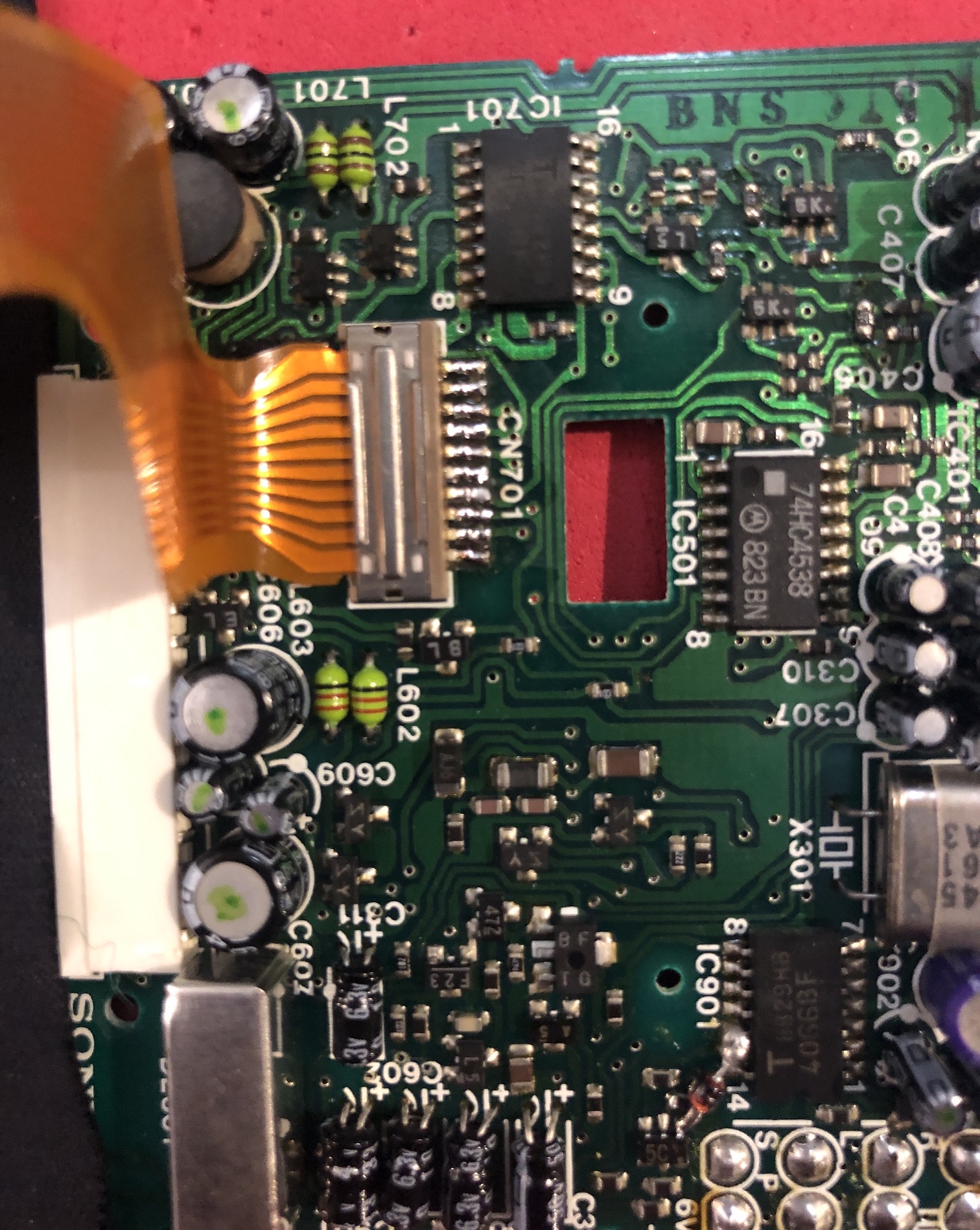
Inverter board. 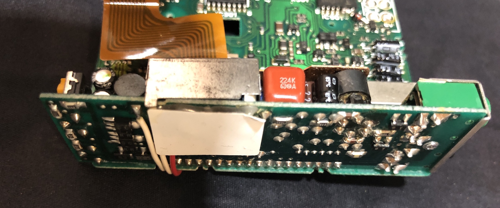
Inverter board can be a pain to take apart from the main board. This inverter board is the one that powers the oldschool LCD backlight. 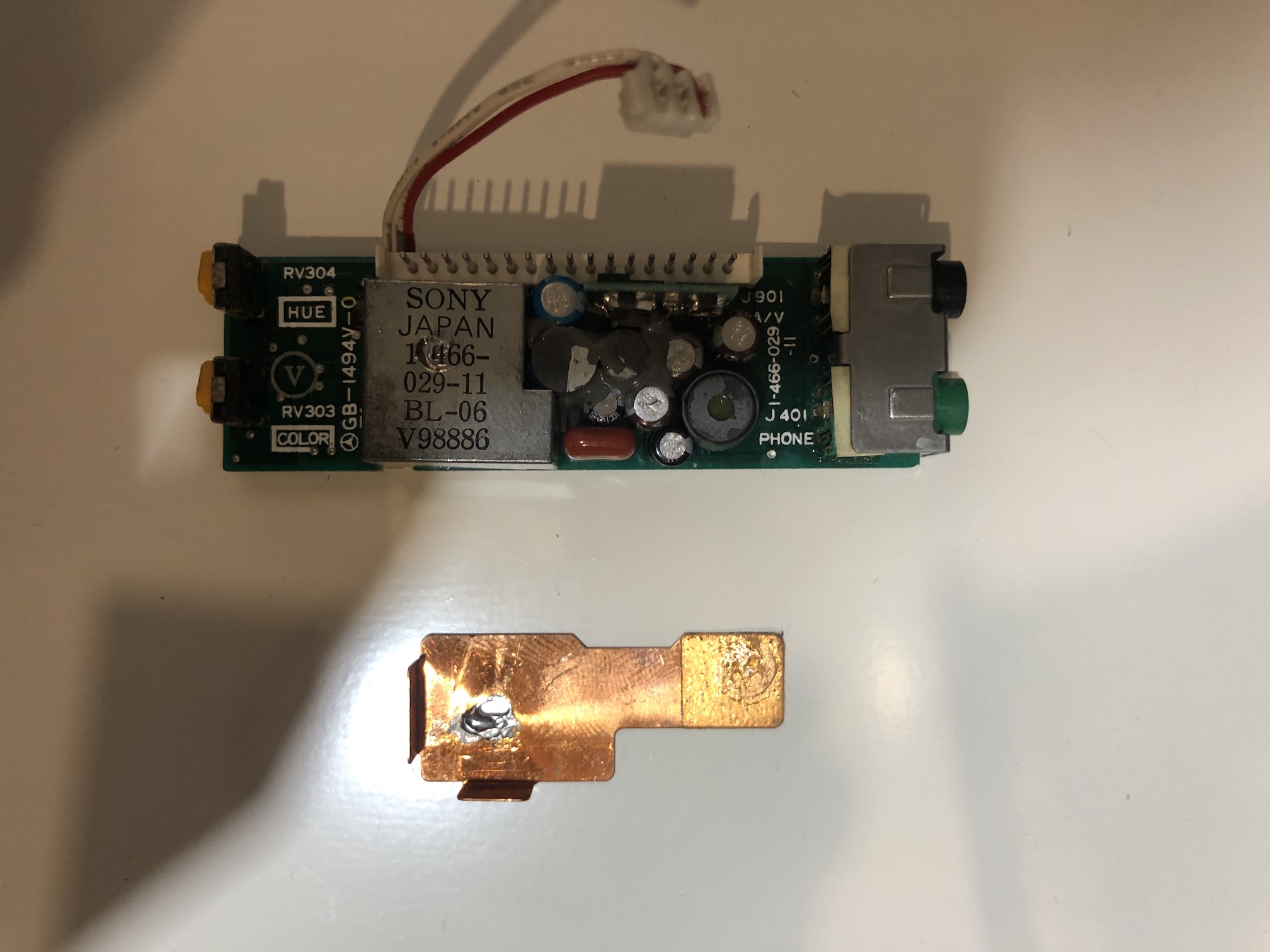
CN701 connector and the ribbon cable that attaches the LCD panel to the mainboard is another weak link. You have to be super careful not to damage it. In my case, I just ended up desoldering it and re-soldering it when I was ready re-assemble.
Issues
The backlight on this unit uses CCFL tubes, similar to Sega Game Gear. Therefore you can see the backlight is not even.
Another issue I noticed was the yellow tint. I'm assuming this is due to the age. I was thinking of removing the top polarizing layer from the LCD and replacing it with a new one. Similar to how Gameboy LCDs were repaired. However, didn't end up doing it.
Capacitor List
It took me quite some time to make this electrolytic capacitor list. However, I'm hoping this will help someone save these rare units. There were around 47 electrolytic capacitors (excluding the speaker module - as I didn't remove the board on that module). Most of them were in great shape except for couple.
There were 6 caps on the inverter board. Several of the inverter board caps were 105C. But, they were all in great shape and were glued together. Therefore, didn't bother to take them apart and measure them.
| V | uF | Location | Current Temp | Height | Diameter/Size | Location Description |
|---|---|---|---|---|---|---|
| 6.3 | 33 | C652 | 85 | 6.5mm | 6.5mm | Tuner Board A |
| 6.3 | 220 | C672 | 85 | 6.5mm | 6.5mm | Tuner Board A |
| 10 | 100 | C663 | 85 | 6mm | 6.3mm | Tuner Board A |
| 35 | 22 | C655 | 85 | 6mm | 6.3mm | Tuner Board A |
| 6.3 | 100 | C666 | 85 | 6mm | 6.3mm | Tuner Board A |
| 10 | 100 | C671 | 85 | 6mm | 6.3mm | Tuner Board A |
| 6.3 | 100 | C667 | 85 | 6.5mm | 5mm | Tuner Board A |
| 6.3 | 220 | C205 | 85 | 6.5mm | 6.5mm | Tuner Board B |
| 6.3 | 100 | C210 | 85 | 6mm | 6.3mm | Tuner Board B |
| 50 | 1 | C217 | 85 | 5mm | 4mm | Tuner Board B |
| 6.3 | 36 | C219 | 85 | 5mm | 5mm | Tuner Board B |
| 4 | 47 | C112 | 85 | 5mm | 5mm | Tuner Board B |
| 6.3 | 22 | C218 | 85 | 5mm | 5mm | Tuner Board B |
| 50 | 1 | C115 | 85 | 5mm | 5mm | Tuner Board B |
| 6.3 | 15 | C605 | 85 | 6.5mm | 5mm | LCD Board |
| 16 | 47 | C607 | 85 | 5.5mm | 6.3mm | LCD Board |
| 10 | 220 | C608 | 85 | 7.2mm | 8mm | LCD Board |
| 10 | 33 | C401 | 85 | 5.5mm | 5mm | LCD Board |
| 10 | 33 | C402 | 85 | 5.5mm | 5mm | LCD Board |
| 10 | 100 | C405 | 85 | 5.5mm | 6mm | LCD Board |
| 6.3 | 10 | C406 | 85 | 5.5mm | 3mm | LCD Board |
| 6.3 | 10 | C407 | 85 | 5.5mm | 3mm | LCD Board |
| 50 | 1 | C902 | 85 | 5.5mm | 3mm | LCD Board |
| 50 | 1 | C902 | 85 | 5.5mm | 3mm | LCD Board |
| 50 | 0.47 | C315 | 85 | 5.5mm | 3mm | LCD Board |
| 6.3 | 10 | C603 | 85 | 5.5mm | 3mm | LCD Board |
| 6.3 | 10 | C602 | 85 | 5.5mm | 3mm | LCD Board |
| 4 | 33 | C601 | 85 | 5.5mm | 3mm | LCD Board |
| 6.3 | 10 | C311 | 85 | 5.5mm | 3mm | LCD Board |
| 16 | 4.7 | C609 | 85 | 5.5mm | 3mm | LCD Board |
| 6.3 | 10 | C610 | 85 | 5.5mm | 3mm | LCD Board |
| 10 | 100 | C606 | 85 | 5.5mm | 6.3mm | LCD Board |
| 16 | 22 | C706 | 85 | 5.5mm | 5mm | LCD Board |
| 6.3 | 47 | C707 | 85 | 5.5mm | 5mm | LCD Board |
| 6.3 | 10 | C308 | 85 | 5.5mm | 3mm | LCD Board |
| 6.3 | 10 | C307 | 85 | 5.5mm | 3mm | LCD Board |
| 50 | 1 | C408 | 85 | 5.5mm | 3mm | LCD Board |
| 6.3 | 10 | C308 | 85 | 5.5mm | 3mm | LCD Board |
| 50 | 1 | C409 | 85 | 5.5mm | 3mm | LCD Board |
| 4 | 33 | C604 | 85 | 5.5mm | 3mm | LCD Board |
| 6.3 | 56 | ? | 105 | 6.5mm | 5mm | Inverter Board |
| ? | ? | ? | 105 | Inverter Board | ||
| ? | ? | ? | 105 | Inverter Board | ||
| 10 | 39 | ? | ? | 6.5mm | 5mm | Inverter Board |
| ? | ? | ? | 85 | 4mm | Inverter Board | |
| ? | ? | ? | 85 | 4mm | Inverter Board | |
| 10 | 470 | C601 | 85 | 8mm | Battery Board |