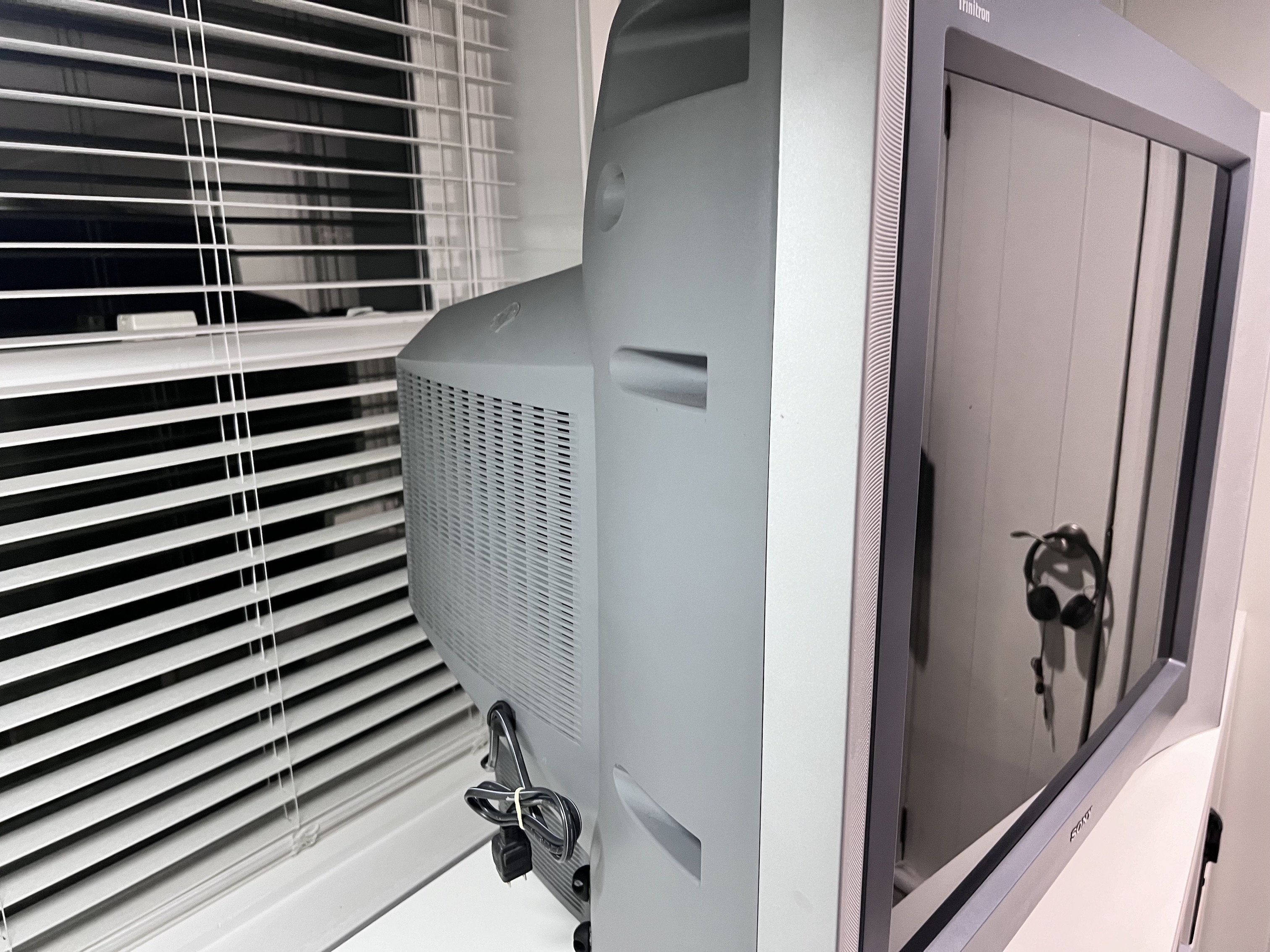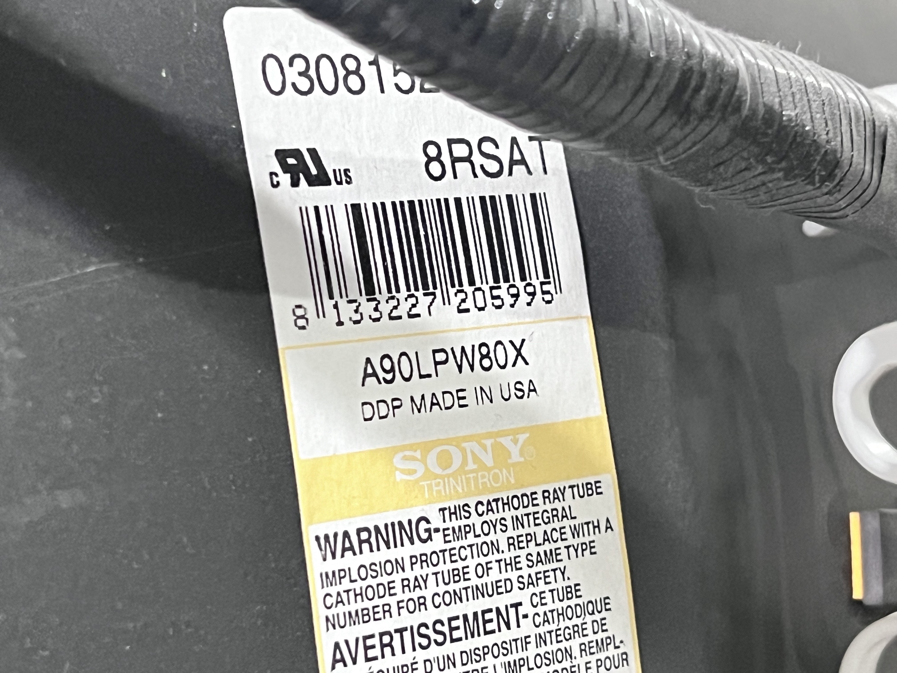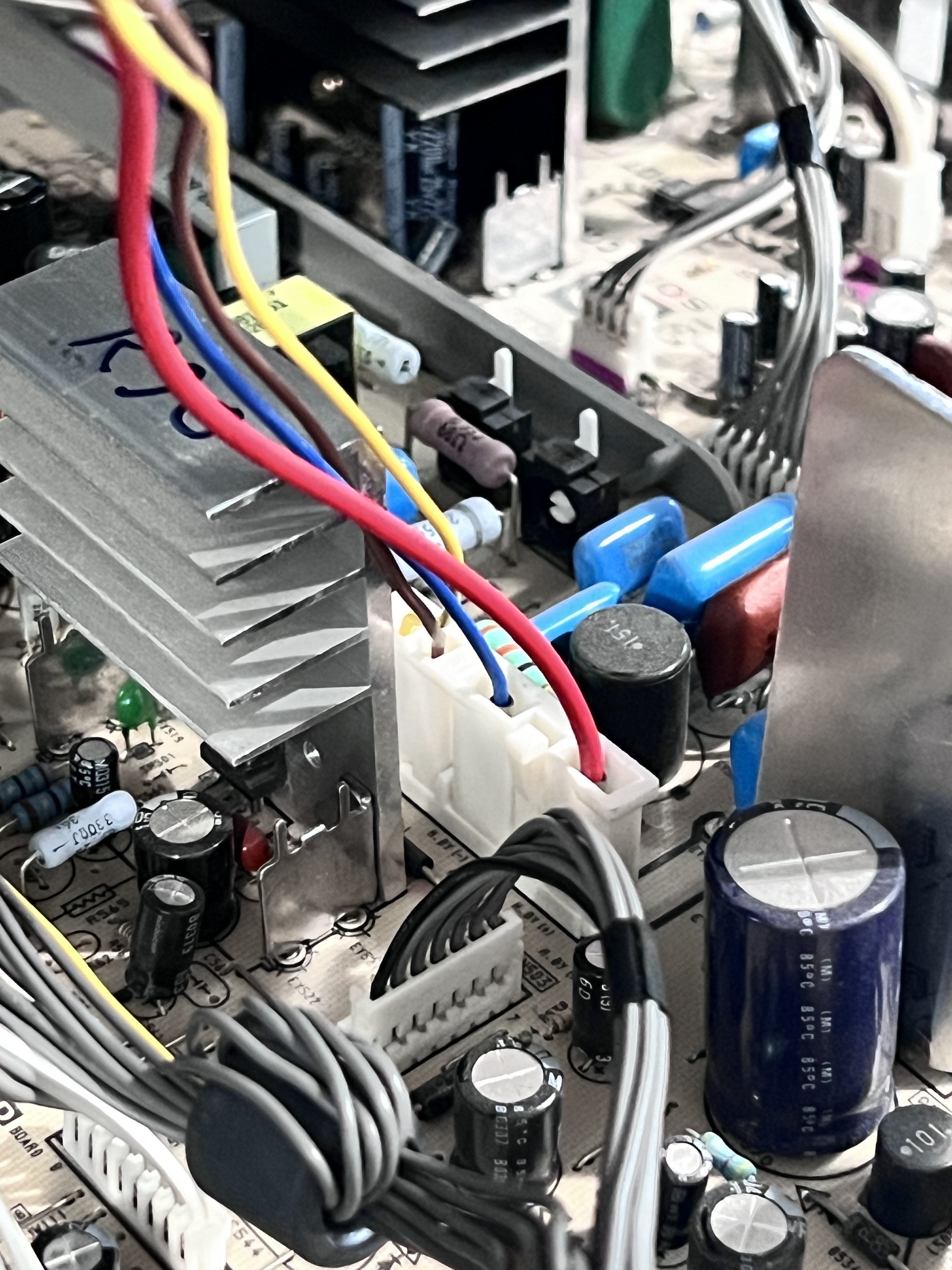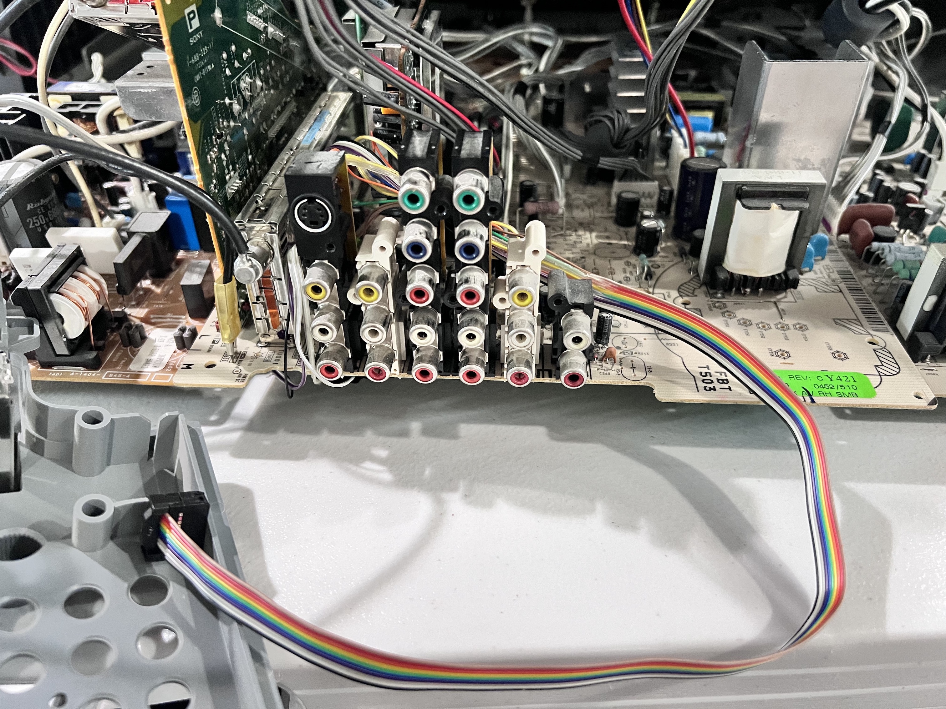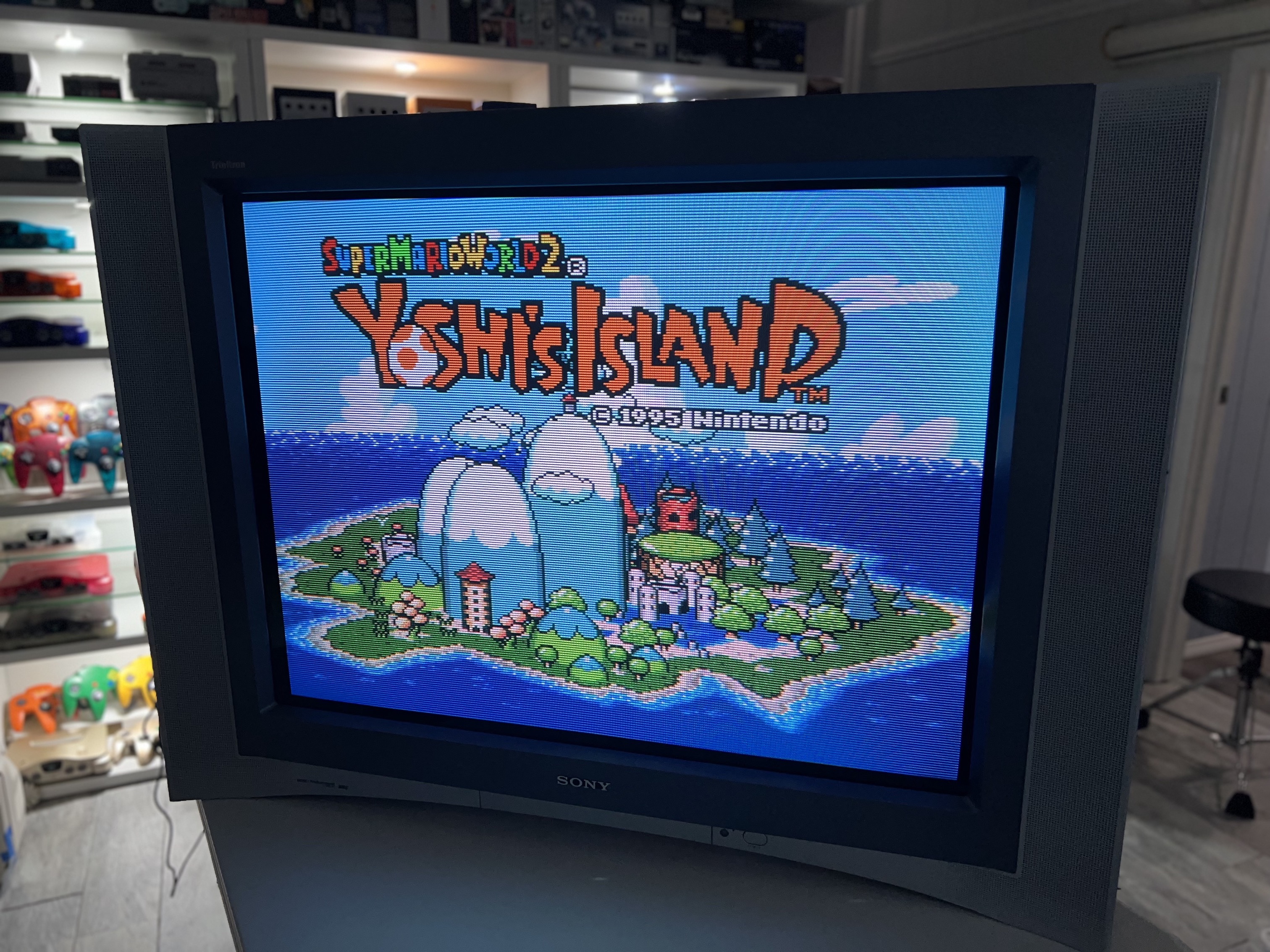
Sony KV (BA-5D) 32FV310
Sony BA-5D chassis (Sony KV-32FV310) CRT RGB mod
Modified by Christopher Cuevas!
After a long runway of working up the courage and skill, I finally RGB modded my precious Sony KV-36FV310 and the results are an ultra-crisp image unaffected by the TVs own artificial picture enhancements!
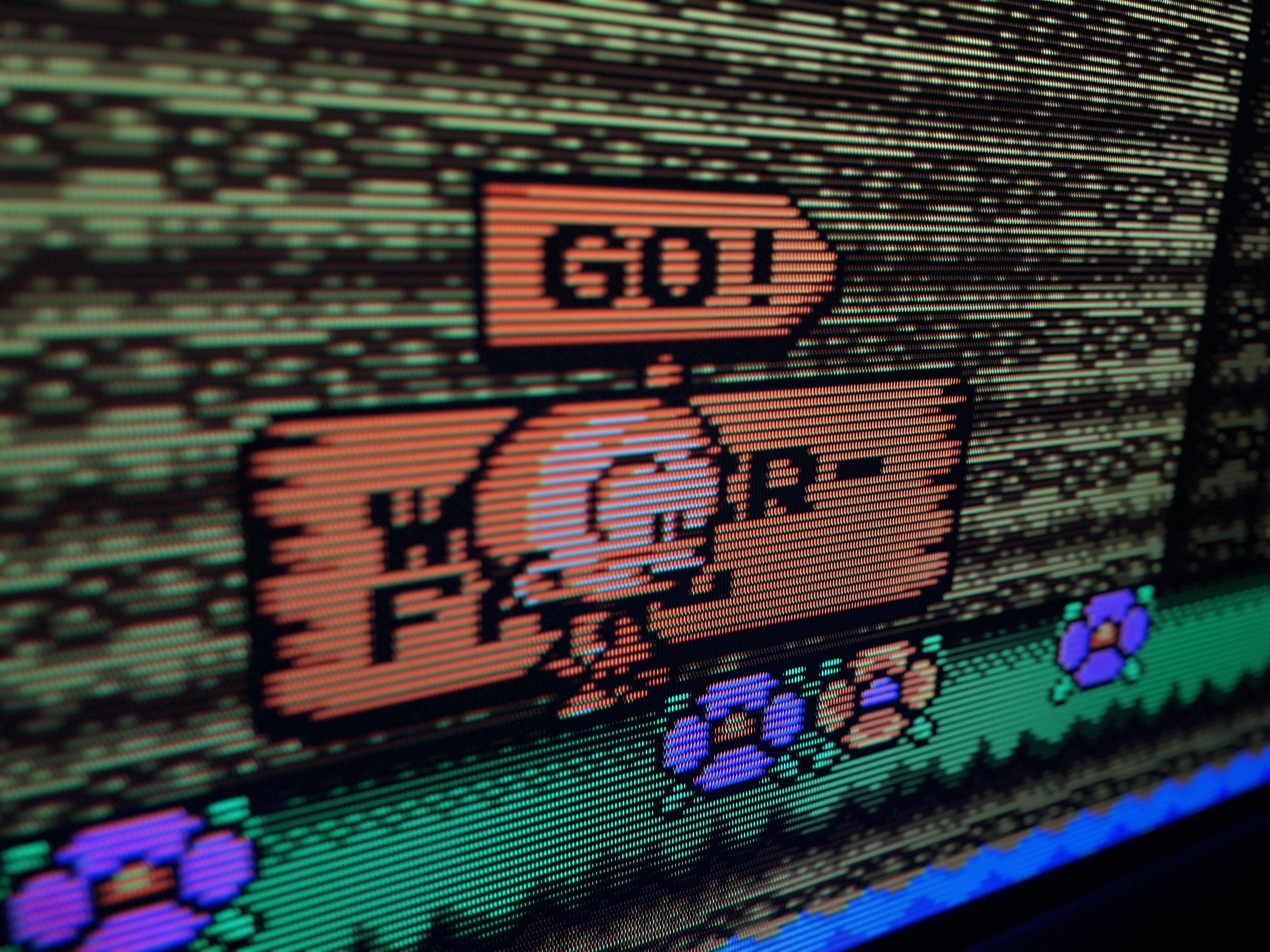
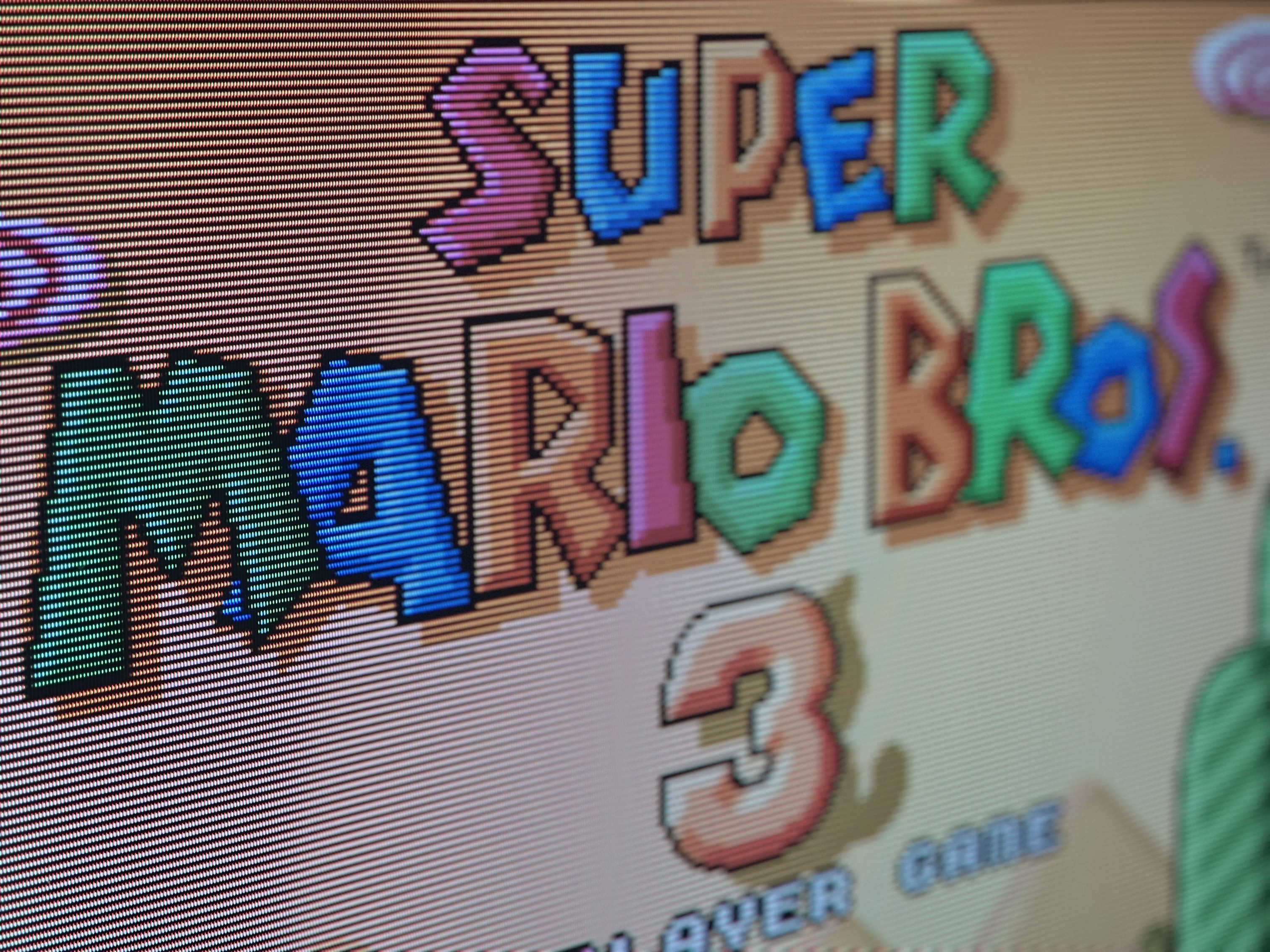
Once I realized a few years back that RGB via SCART was more cost effective at scale and bypassed the processing TVs apply to an image, I’ve wanted to see what a pure RGB signal looked like on a large consumer set as sought-after as the FV310. I’ll admit that it isnt a tremendous jump over the previous RGB to Component transcoded signal I had before, I can absolutely notice the difference when artificial enhancements like velocity modulation, Dynablack, red push, sharpening, color and hue changes are no longer impacting the picture. When connected via RGB, the only adjustments are contrast (picture) and brightness.
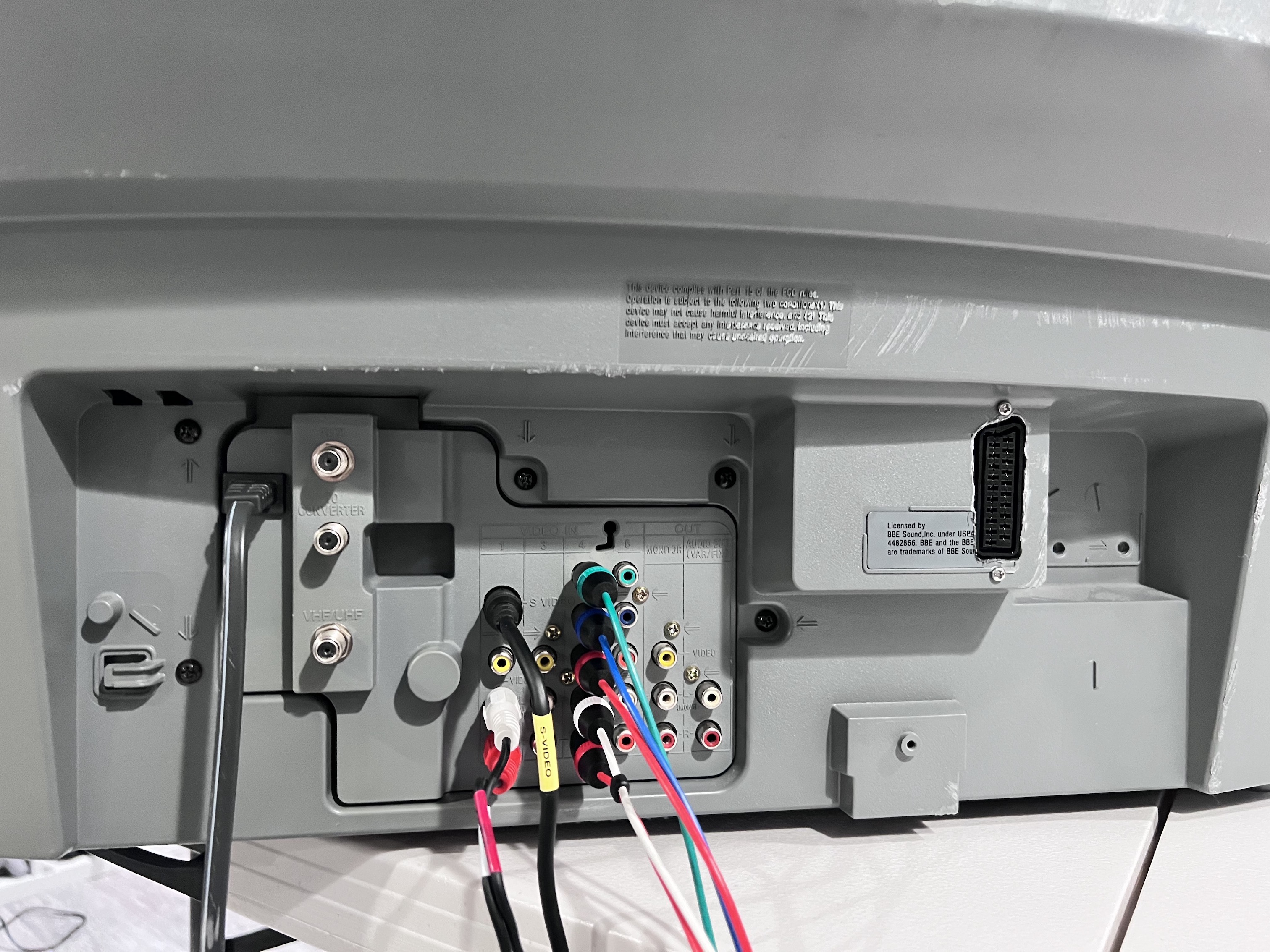
Much like the KV-27S25 I modded for RGB, this one requires something to be plugged into the right audio port of the Video 1 input to enable stereo audio (the tv assumes mono otherwise) but does NOT require something in the S-Video port to enable sync. I have cables plugged into those ports anyway (for anything S-video like a laserdisc or PC-FX) and the default behavior of the all the original composite, s-video and component ports on the front and rear remain unchanged.
I used Sunthar’s RGB mux board for the mod, and the installation itself wasn’t any more difficult than the 9” and 27” trinitrons I modded previously. The insane size, weight and complexity of this thing absolutely made it feel more difficult than previous mods, with me having to disconnect substantially more wiring harnesses to completely remove the board I needed to work on. With that said, it was absolutely worth it to be able to remove the A board from the TV so that I could take my time and have the proper space to perform the modification. Anyway, I’m super happy with the results. I’m not suggesting this is a must-perform mod by any means, but I love that my setup is now simplified with direct RGB access and that I no longer have to fuss with getting the settings in the menu & service menu just right in disabling the artificial enhancements. Having the component inputs freed up for other devices is also a nice bonus, despite already having a component switch.
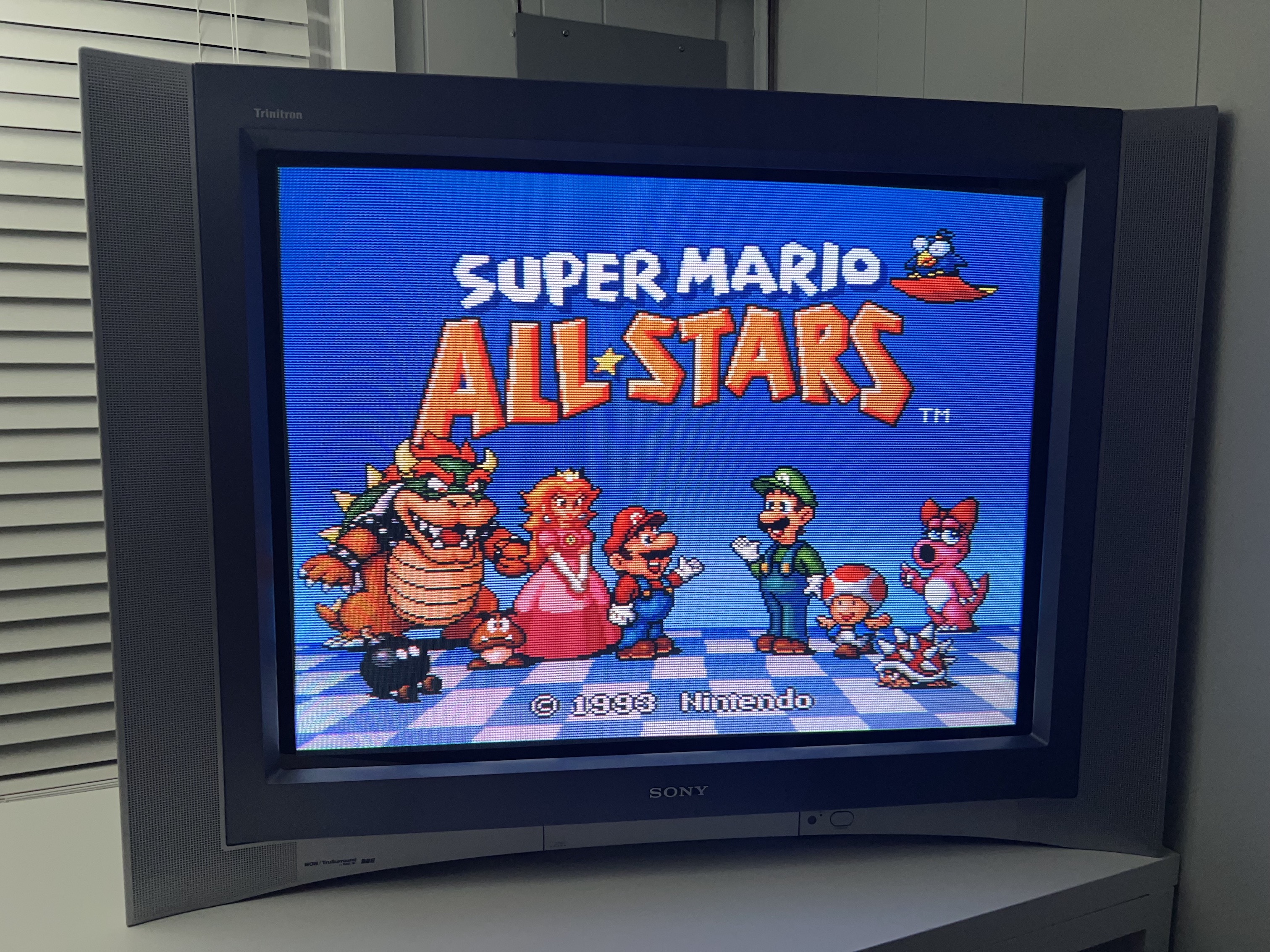
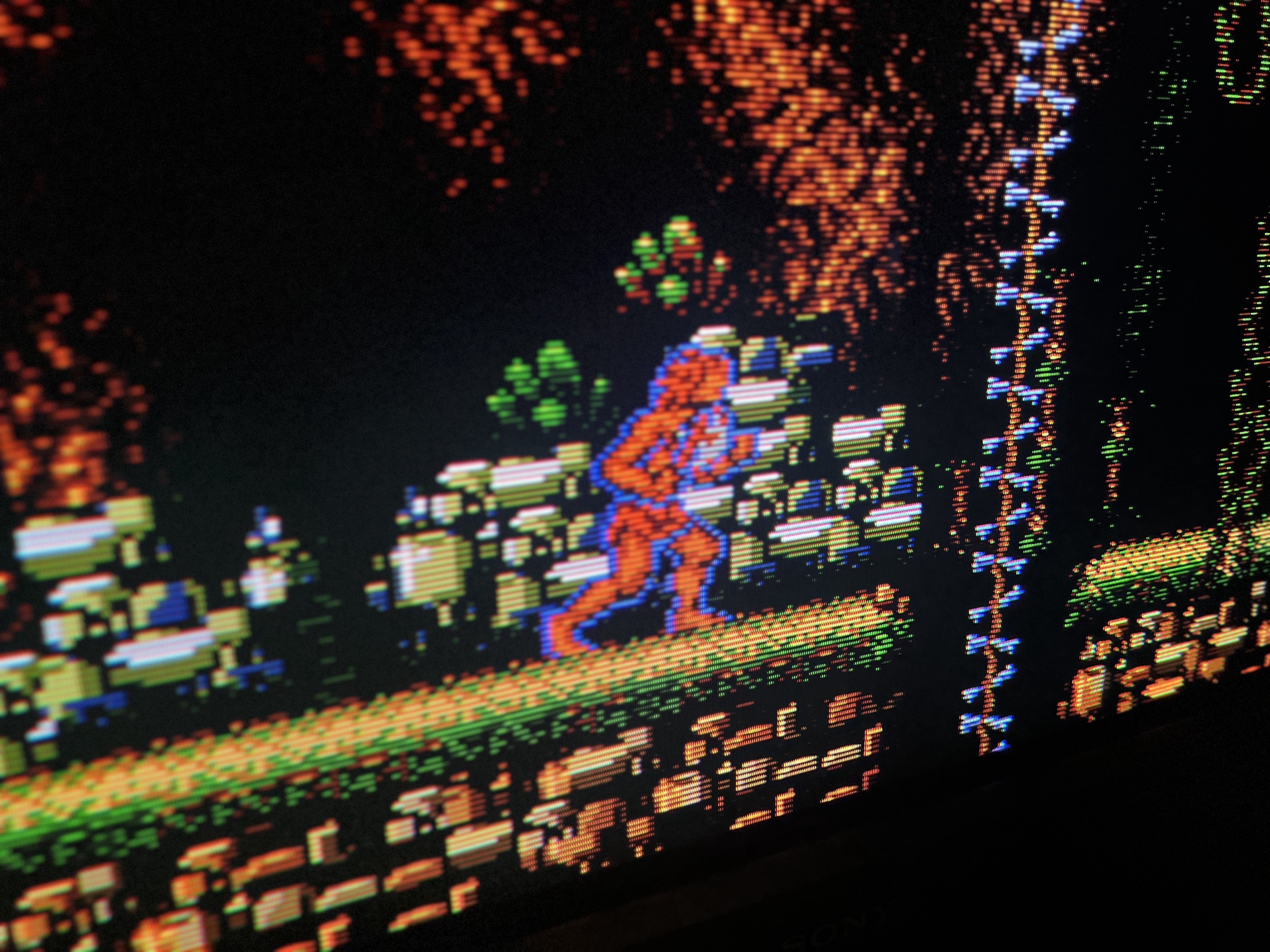
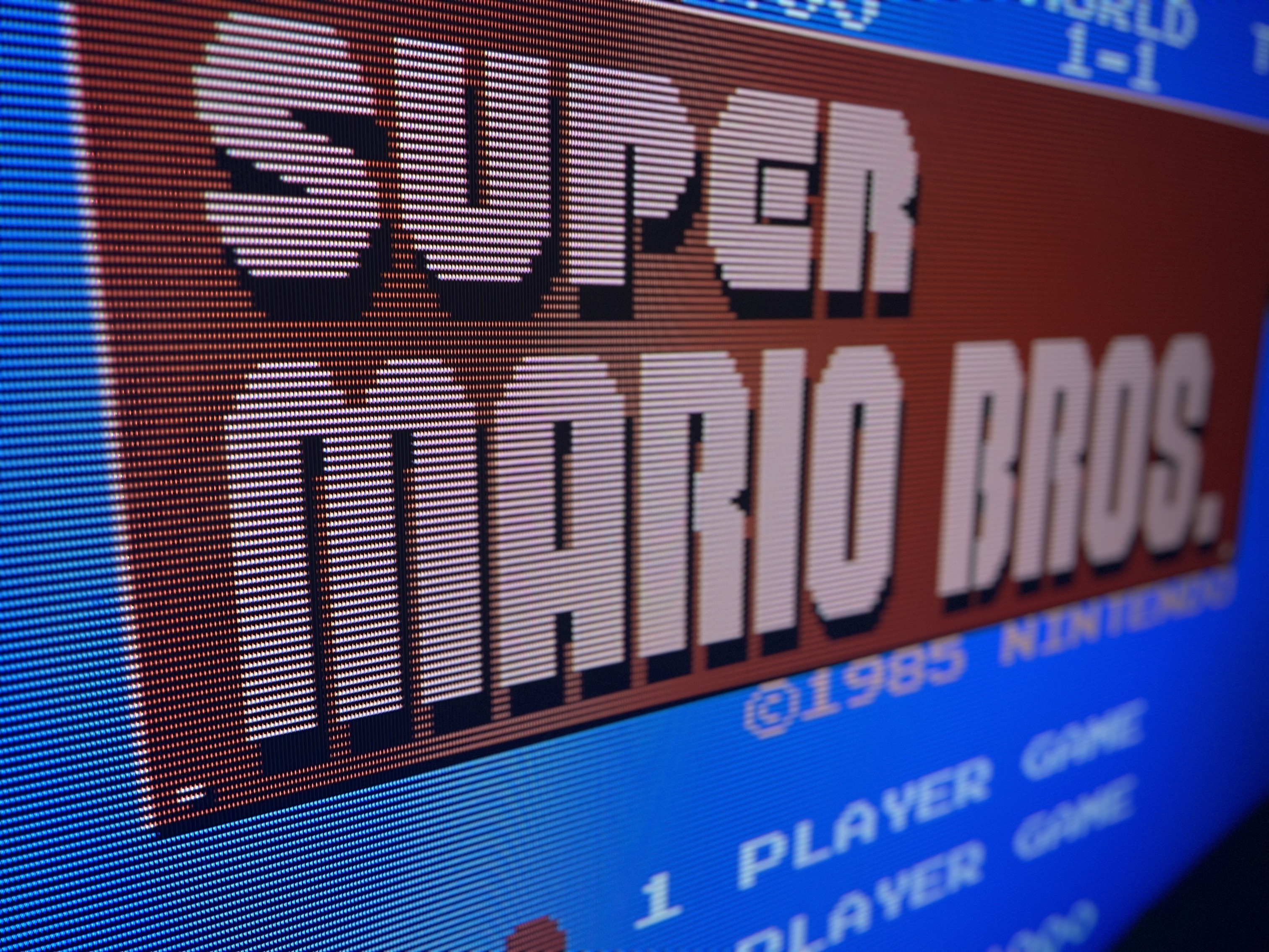
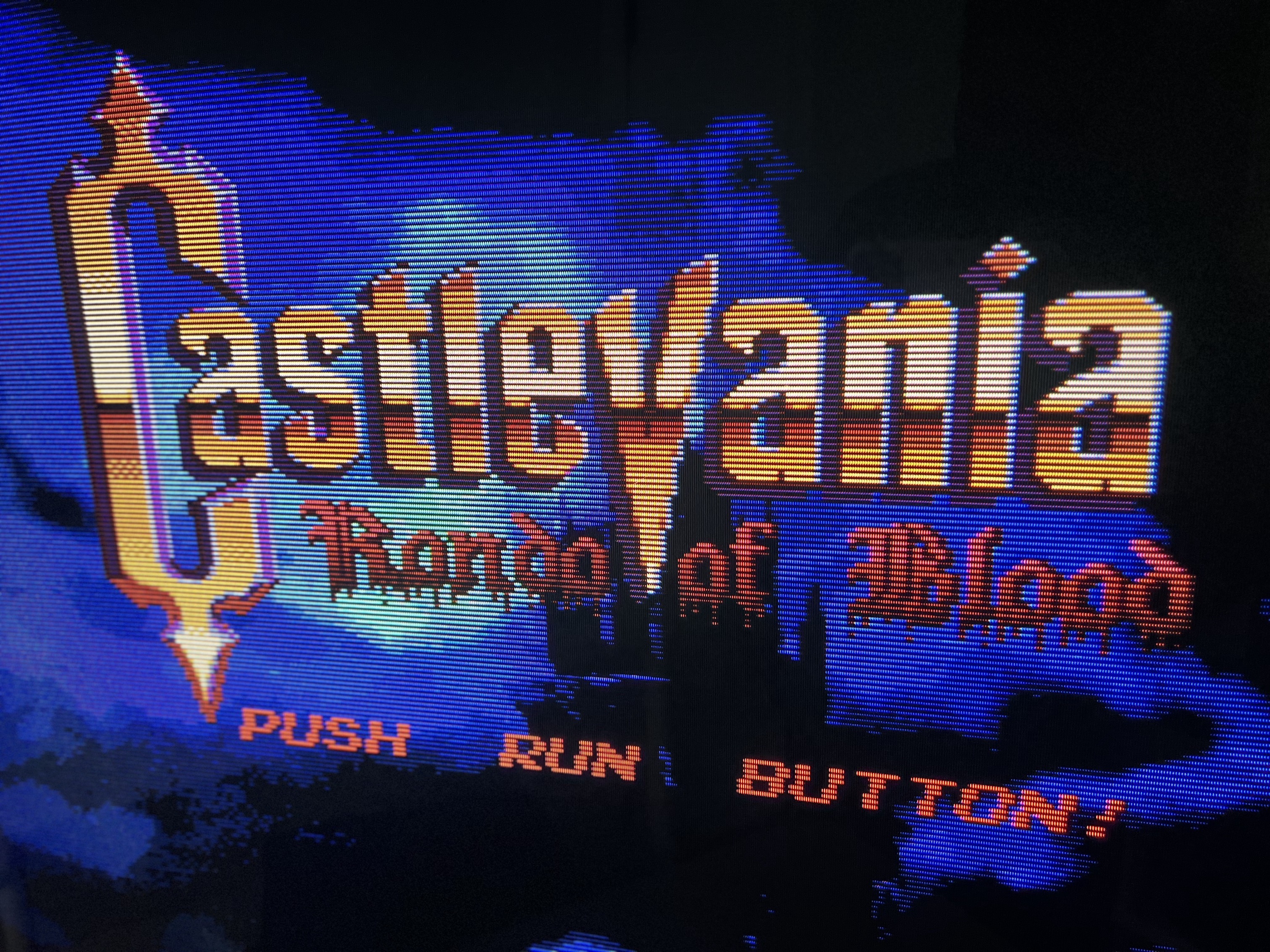
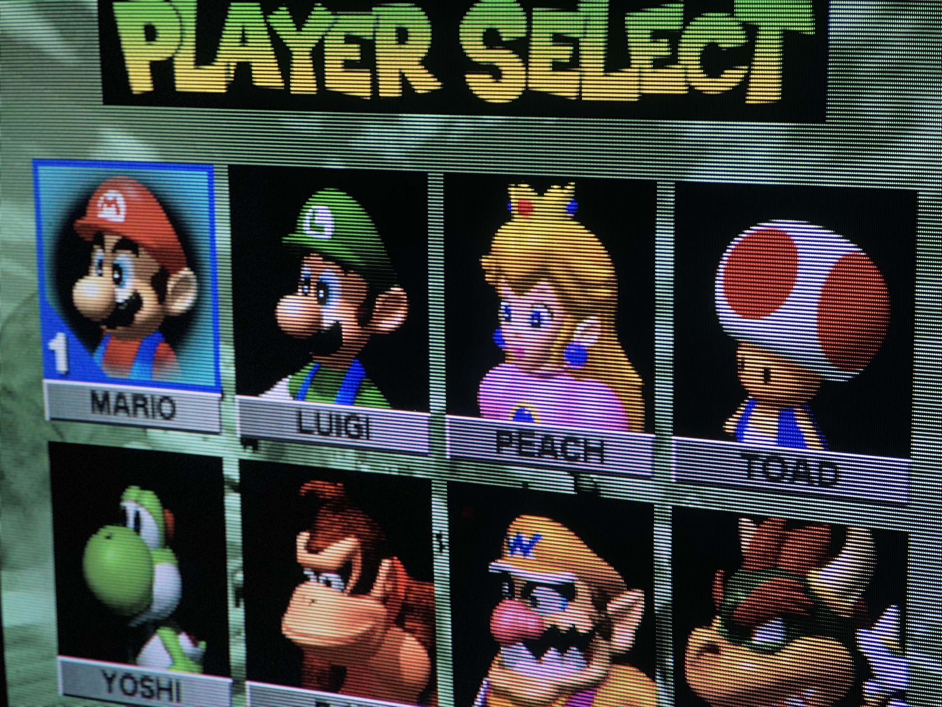
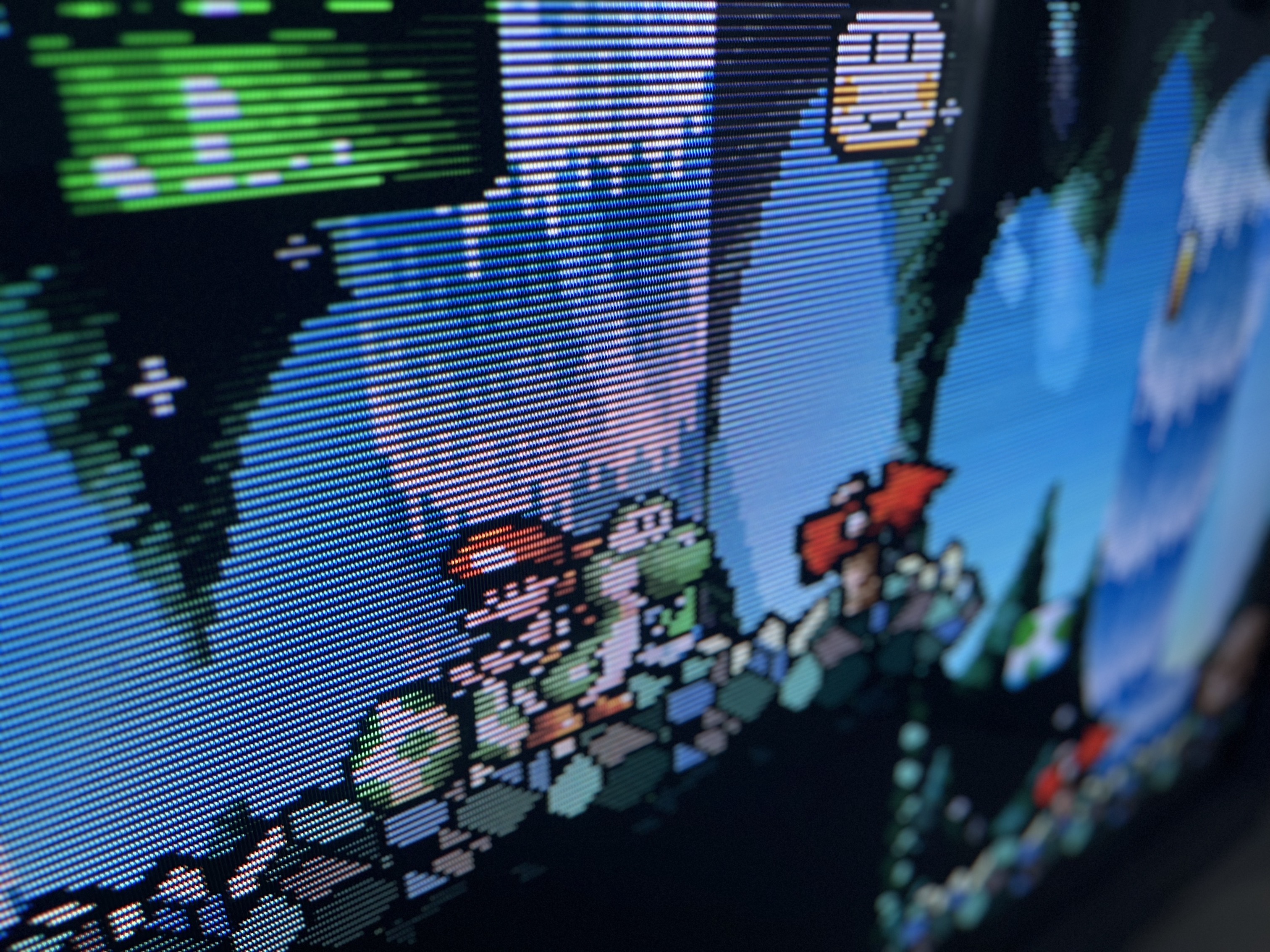
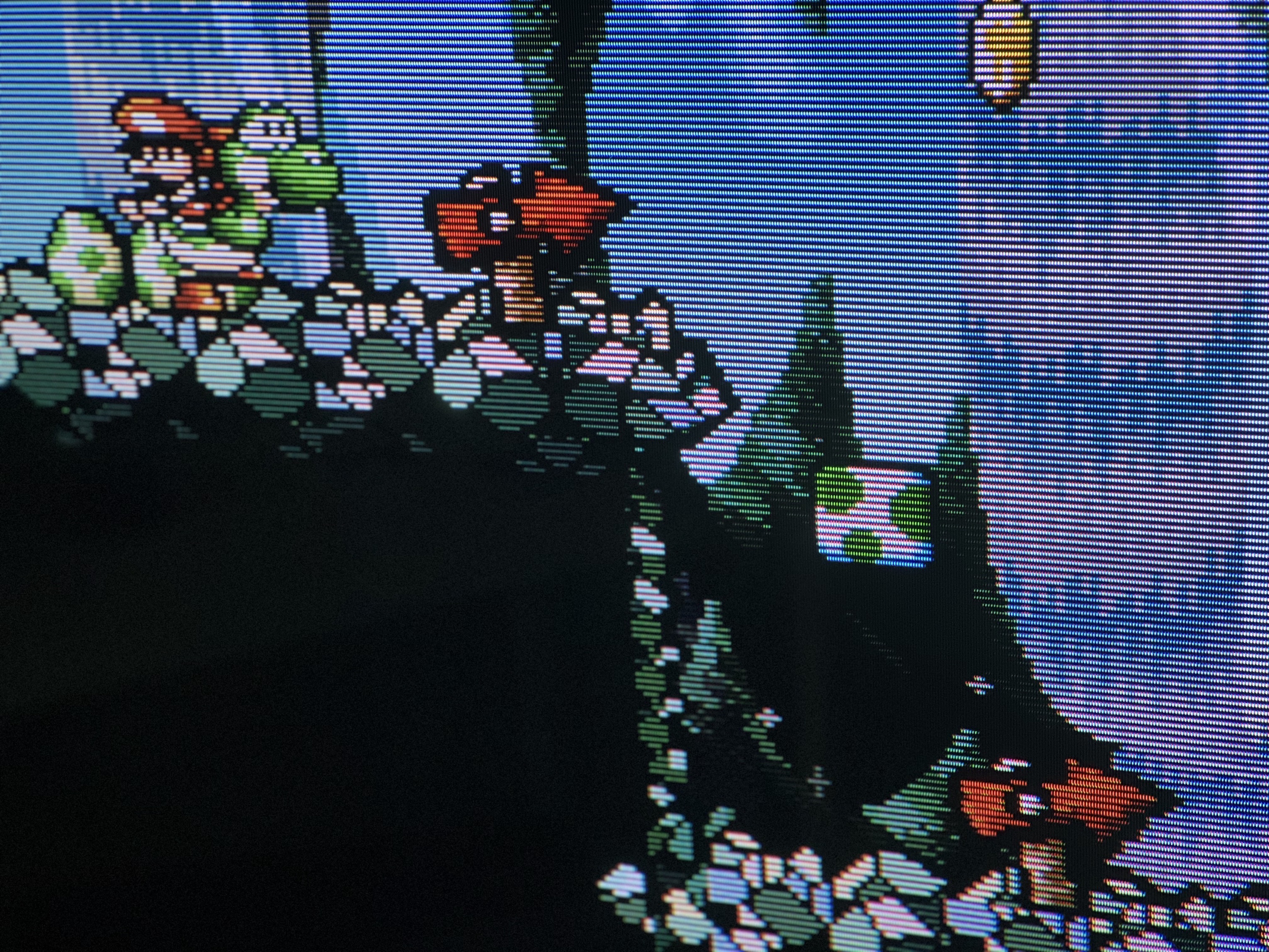
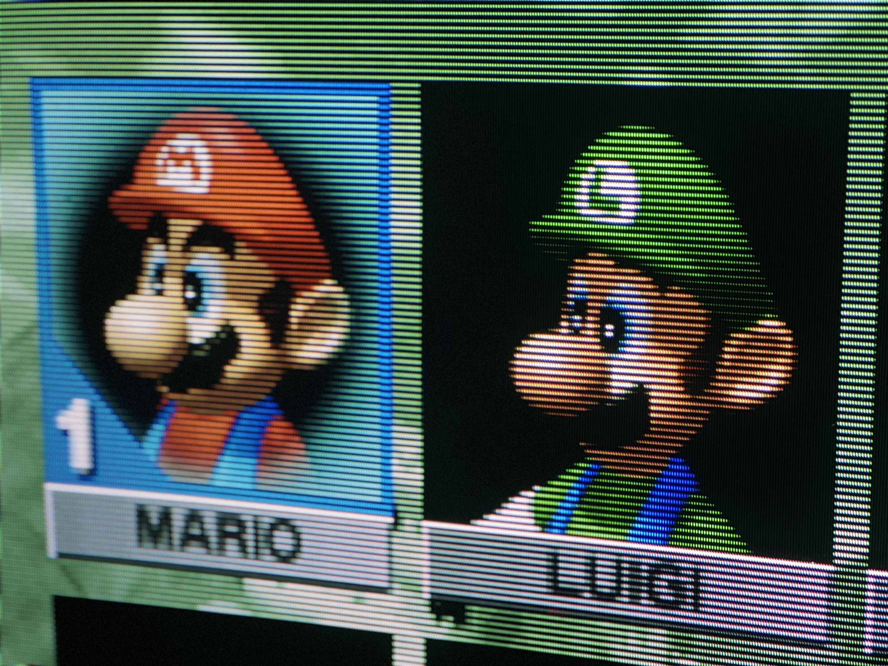
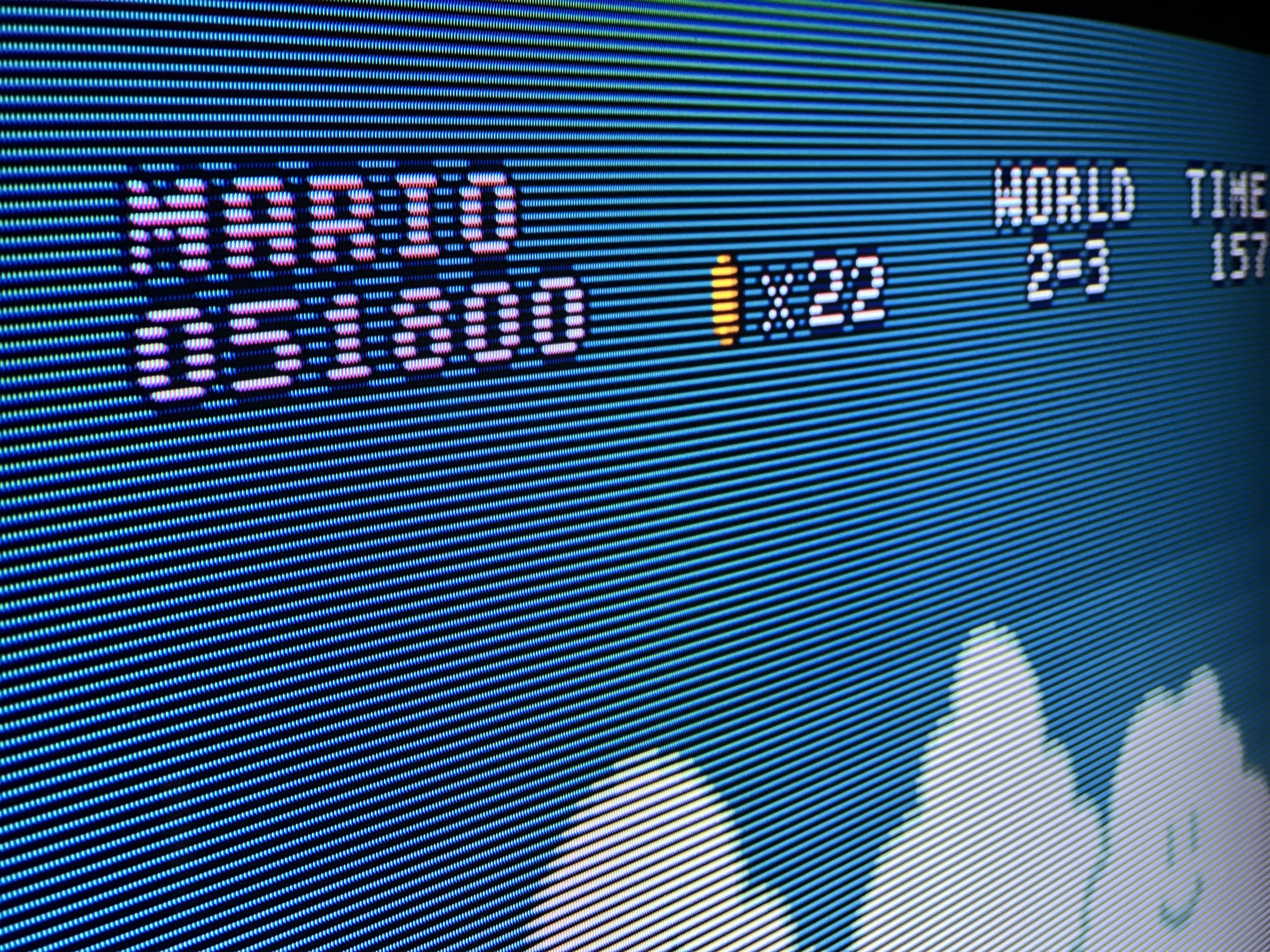
Sometime in the near future I may get in there to do some more geometry adjustments and file down the scart cutout. Enjoy the pics I took of the process and the resulting thick, beautiful scanlines.
Special thank you to Sunthar for the amazing mod kit, instructions and patience of a saint as I fumbled my way through this process. Also shoutout to George Portugal who helped me troubleshoot when I swapped two of the wire harnesses on reassembly and Pickles Jar who let me practice on RGB modding his FV310 first. Couldn’t have done it without all the help!
- KV-27FV310
- KV-29FV310
- KV-32FV300
- KV-32FV310
- KV-34FV310
- KV-36FV310
- KV-38FV310
CRT safety
Caution
You can die doing this! So read carefully! CRT TV is not a toy. Do not open a CRT TV. If you don't have any prior knowledge about handling high voltage devices, this guide is not for you. CRT TV contains high enough voltage (20,000+ V) and current to be deadly, even when it is turned off.
Plan of attack
Theory
Sometimes it is nice to know the theory behind the mod. I have put this on a separate page. This shows how the various resistor values are calculated.
Service manuals
Schematics
Mux diagram 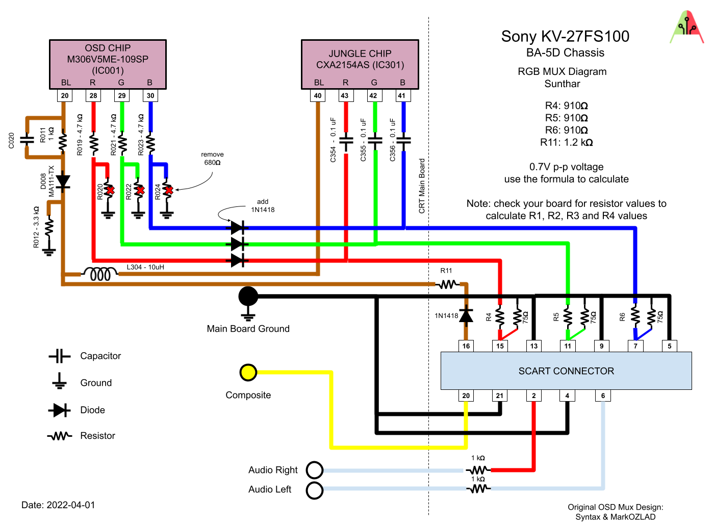
Relevant schematics 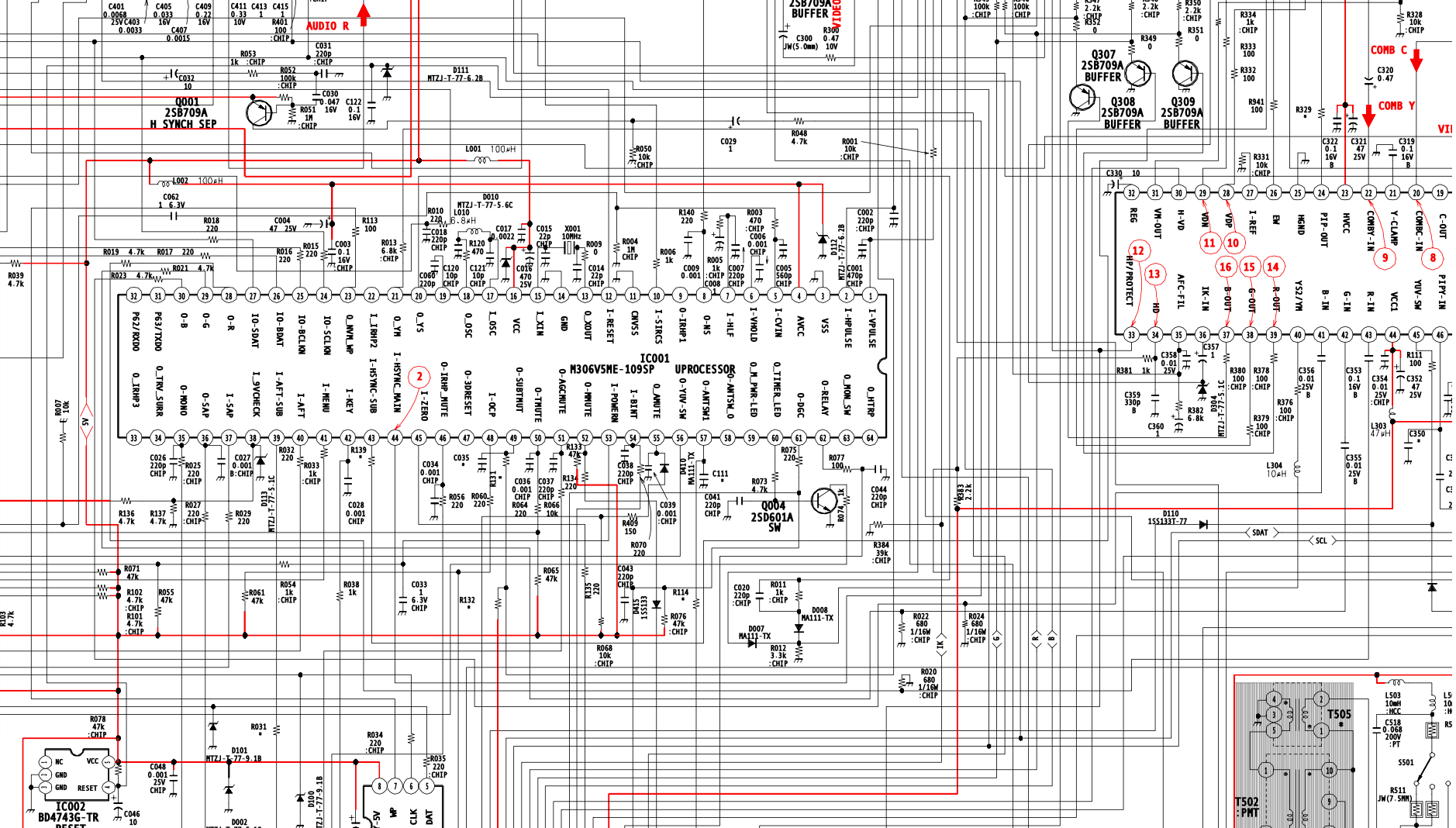
Performing the mod
Now that you roughly know what needs to be done, prepare for the mod. Place the board on a comfortable place. Make sure you are not putting pressure on the flyback or other components. There are few wires that needs to be disconnected.
- Degauss wire
- Power wire
- Ground wire attached to the neck board
- Yoke deflection coil wire
- Anode wire (this is the one with the rubber cap)
- Left and right audio wires
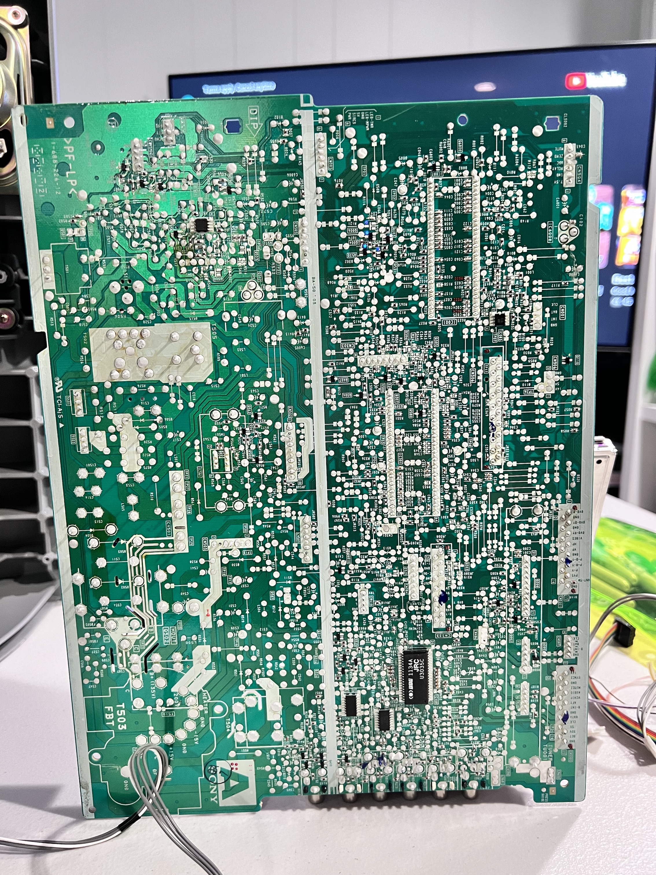
STEP 1: Remove the following components
- R020
- R022
- R024
Before removing resistors 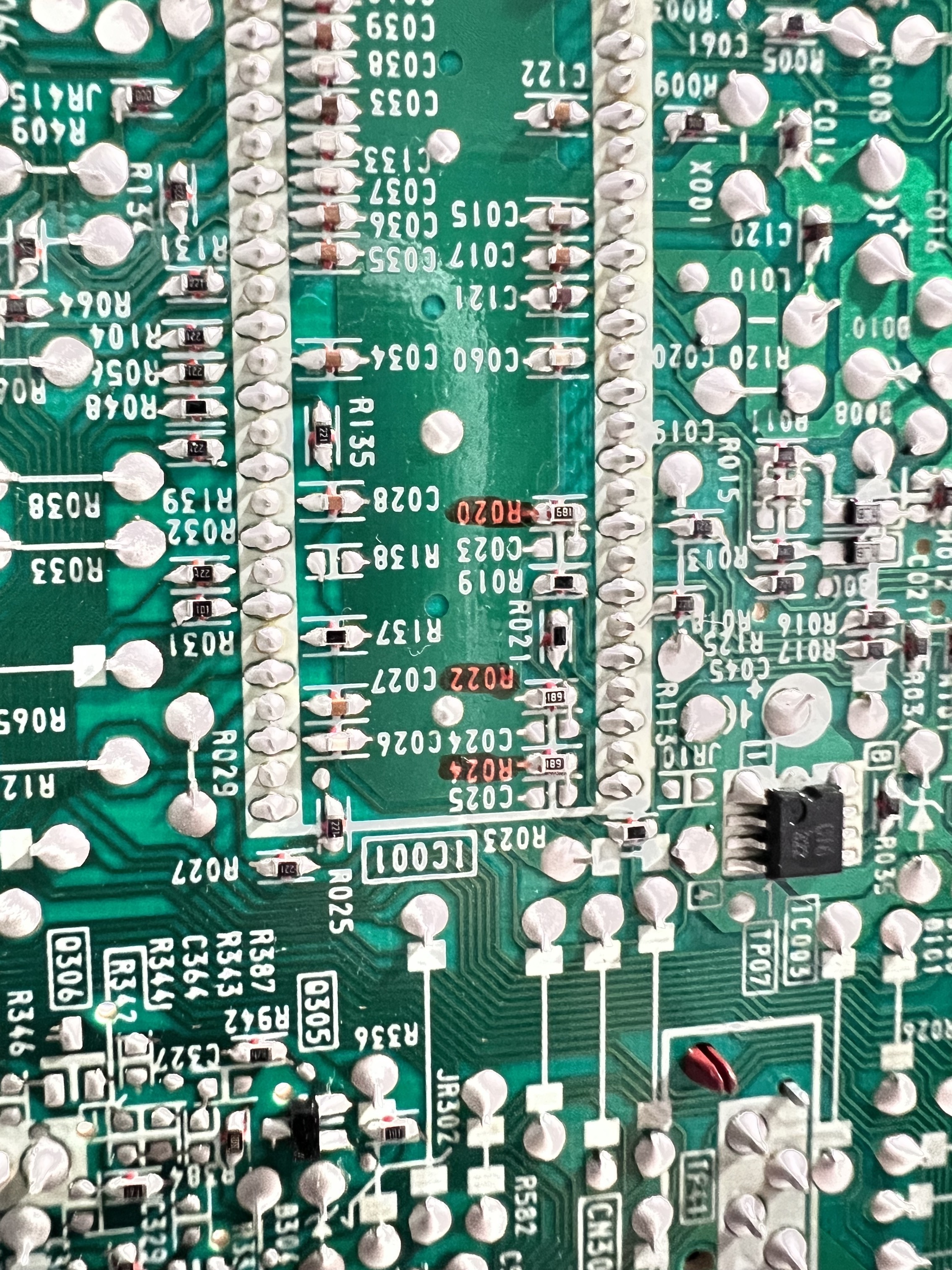
After removing resistors 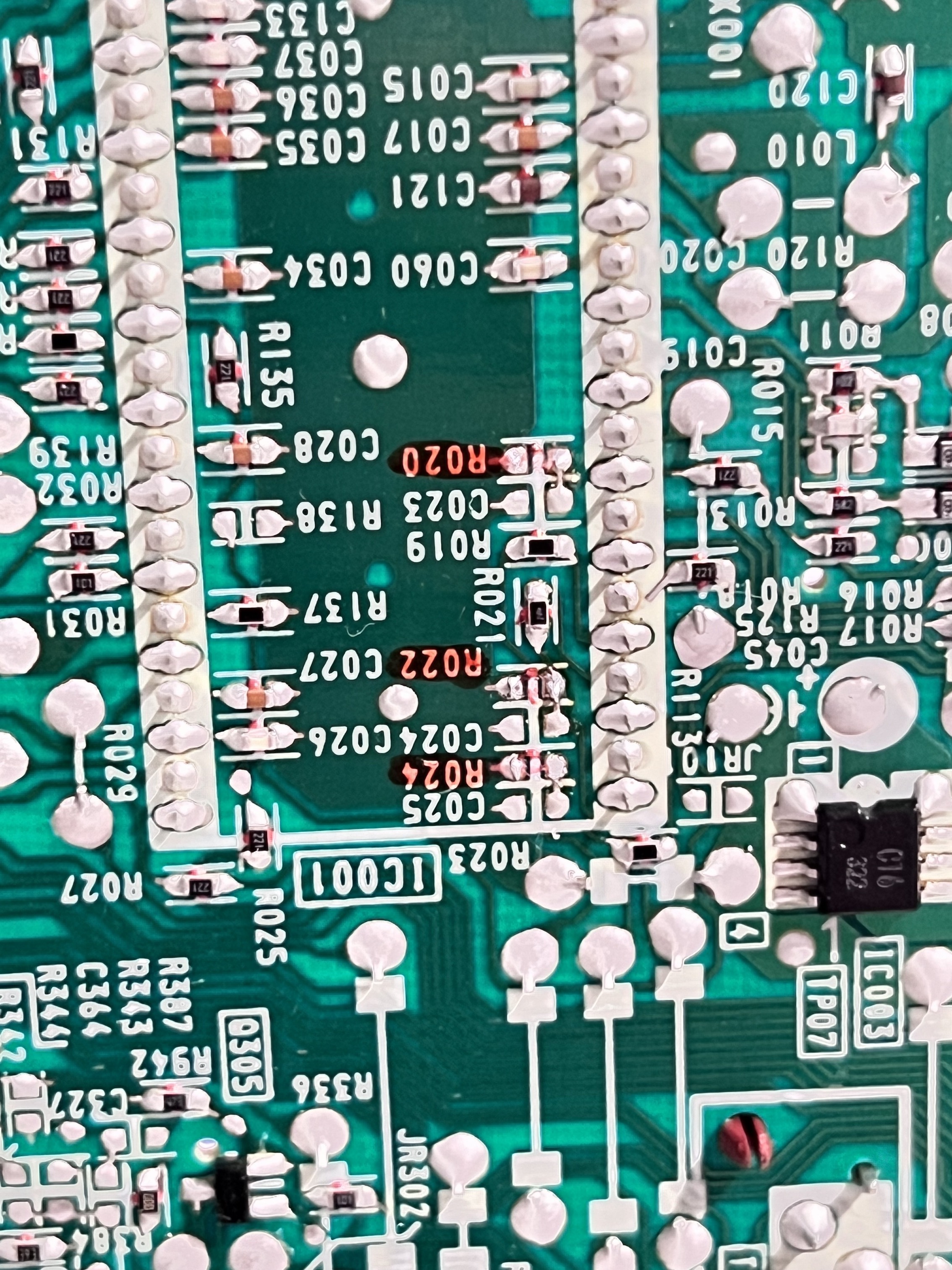
STEP 2: Connect RGB
Find jumpers JW42 (green), JW43 (blue), JW44 (red).
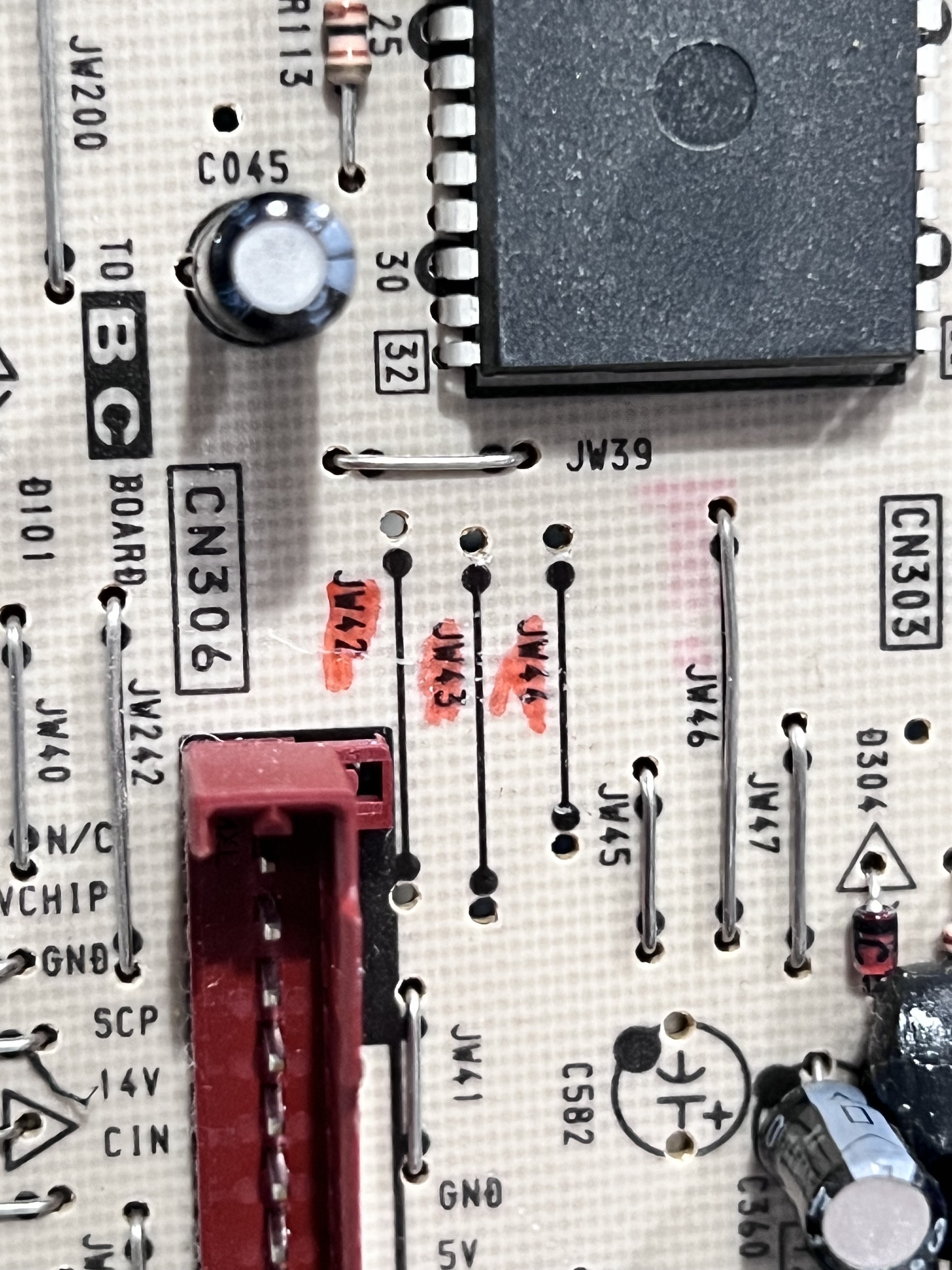
Replace them with diodes.
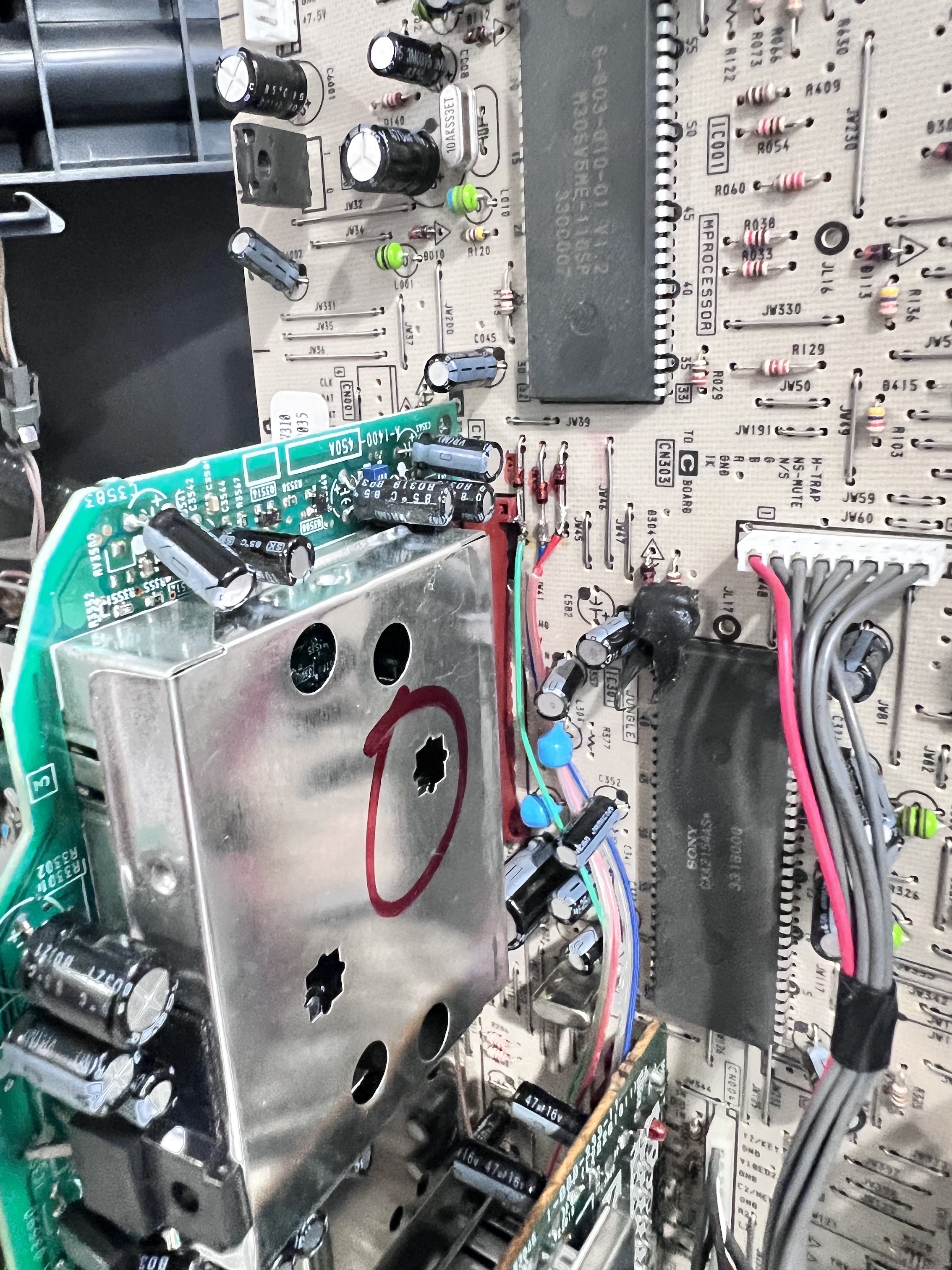
STEP 3: Connect Blanking
3V is the caluclated voltage for blanking. We can calculate 1.2kΩ resistance needed on the RGB mux board with a diode to produce the correct blanking voltage.
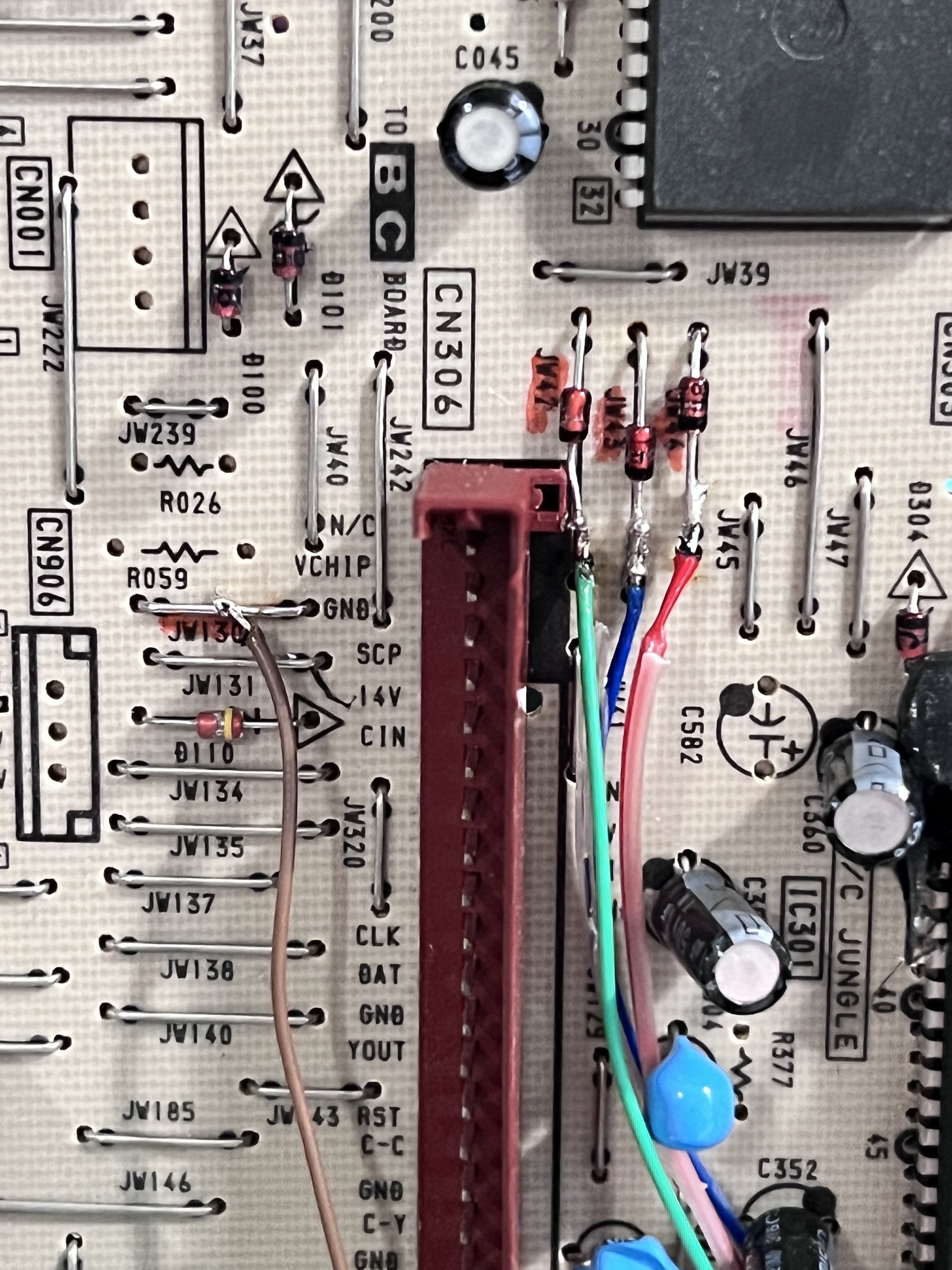
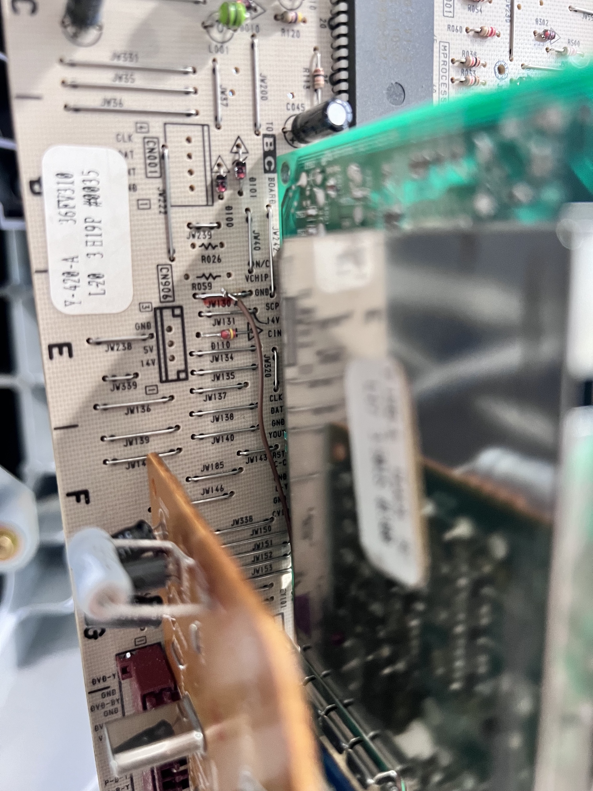
STEP 4: Connect Sync
Below picture is from KV-36FS100. But, the idea is the same. 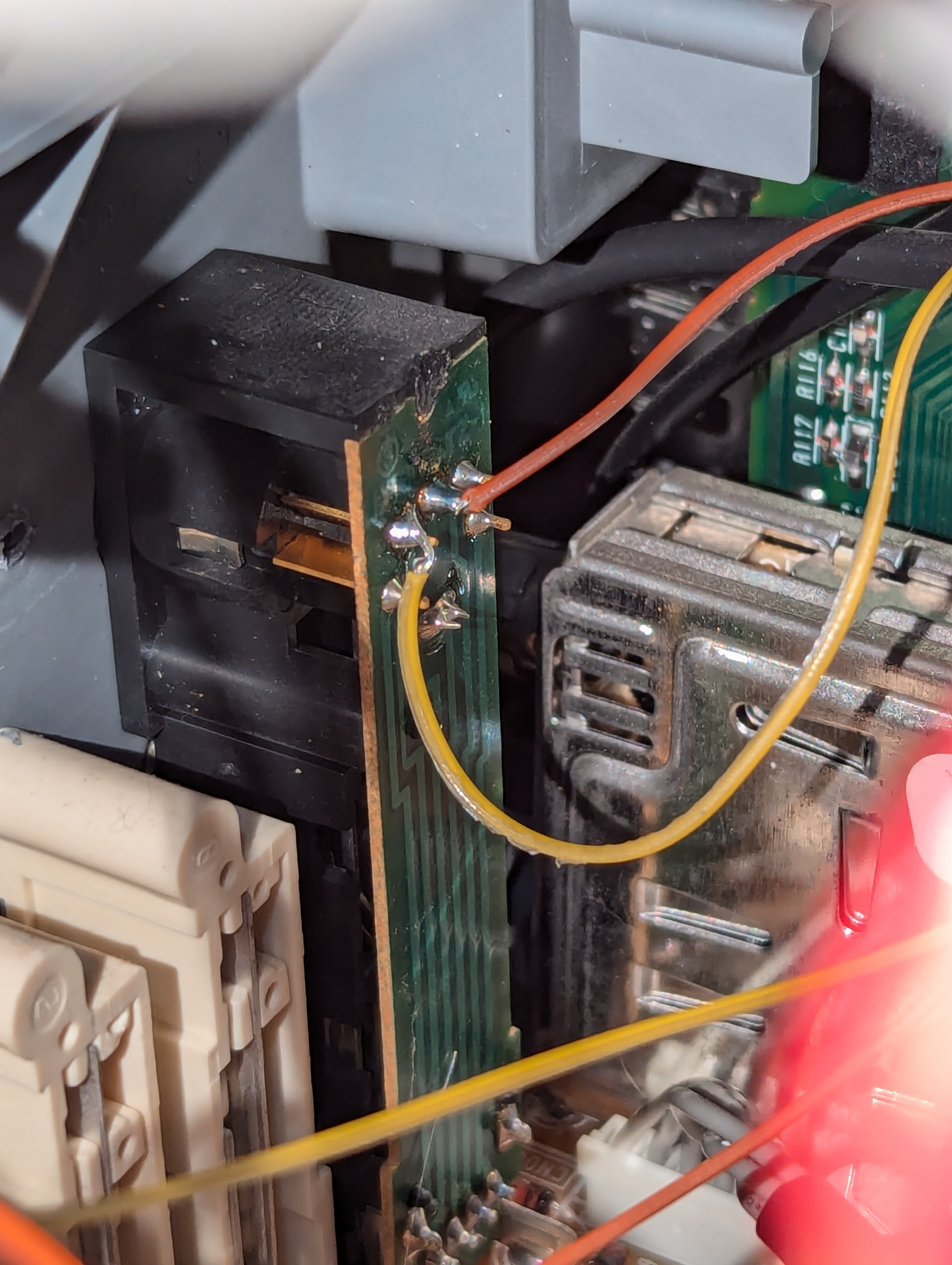
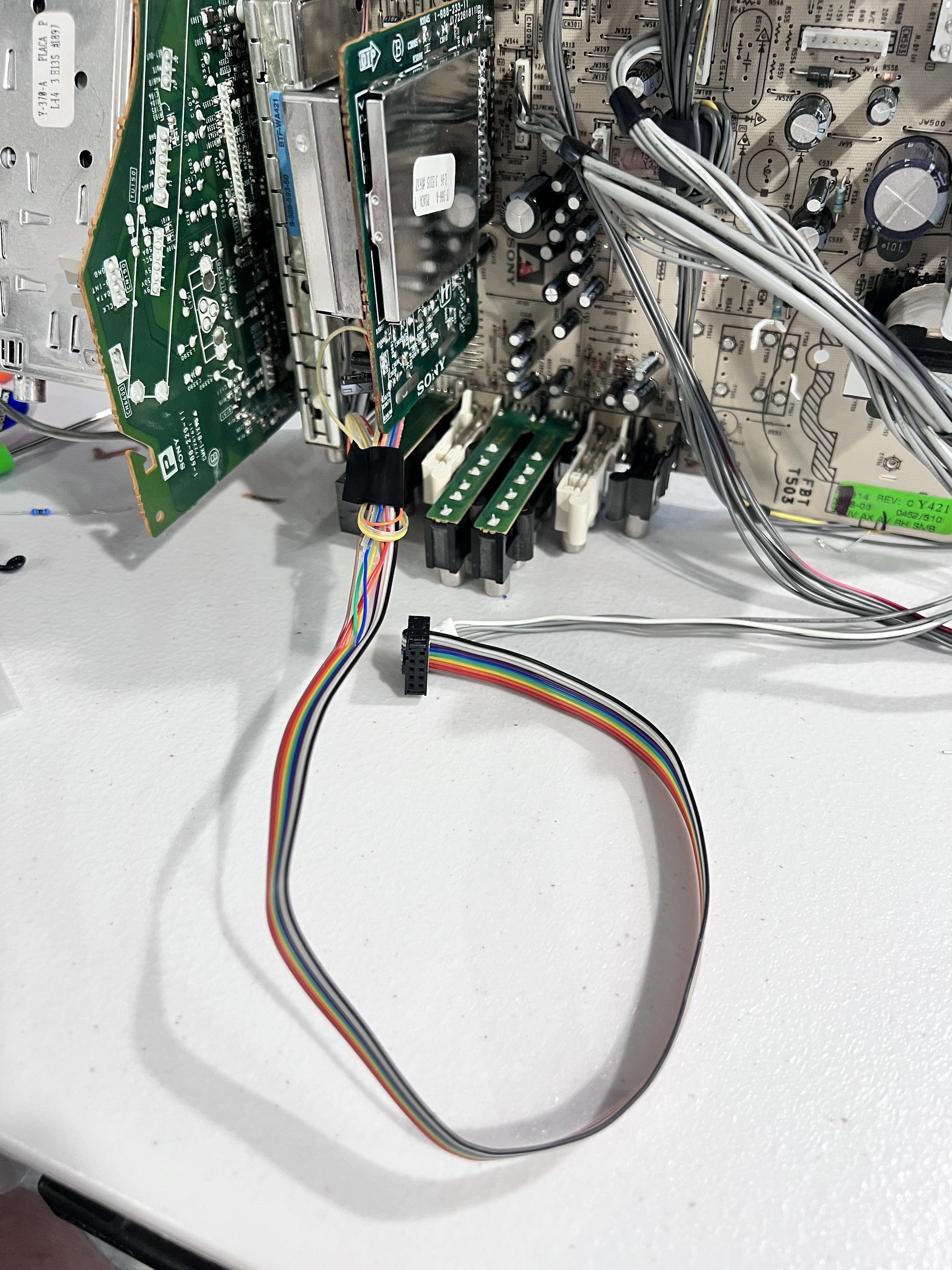
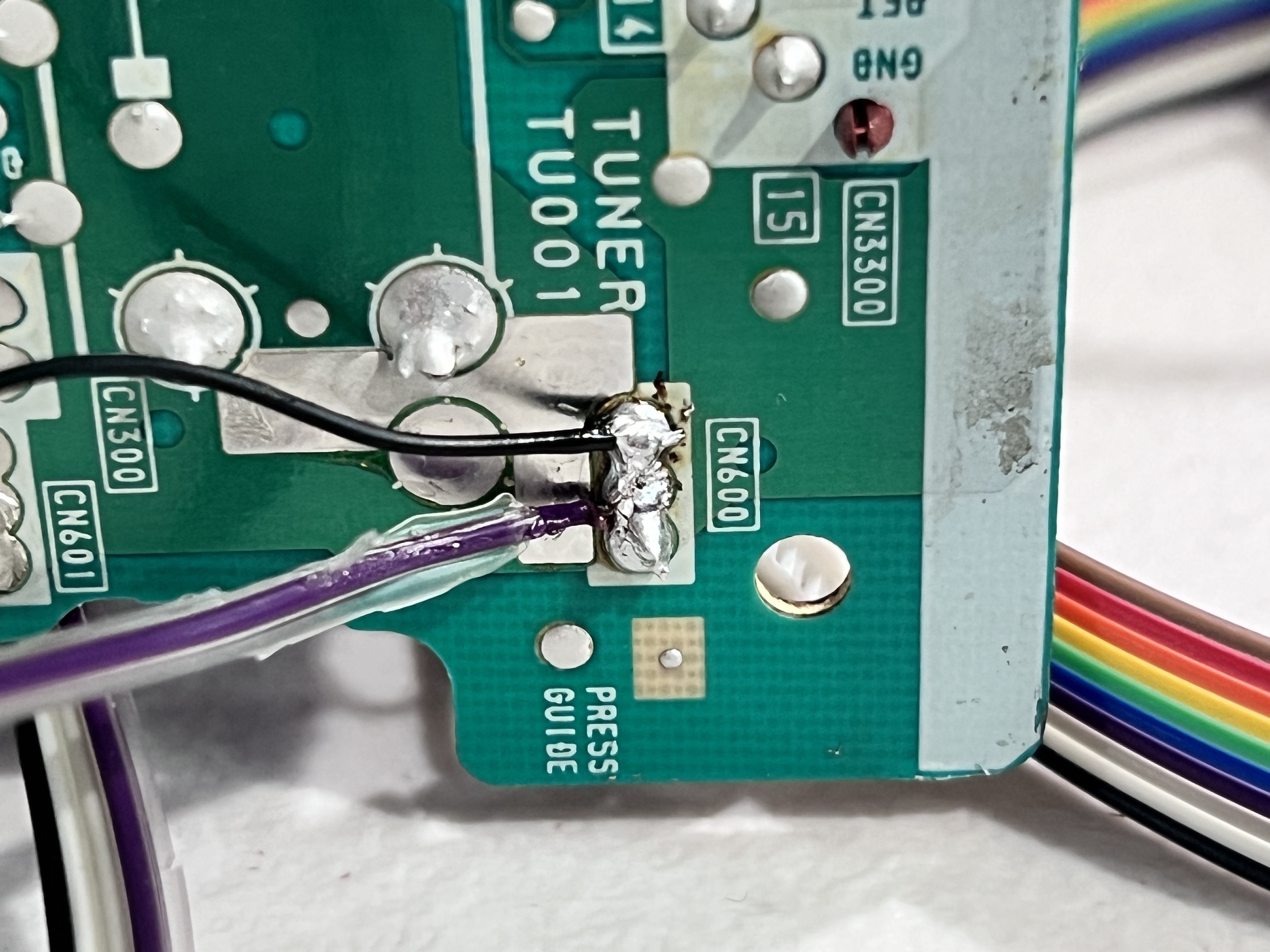
STEP 5: Connect Ground and Audio
Audio Left and Audio Right wires 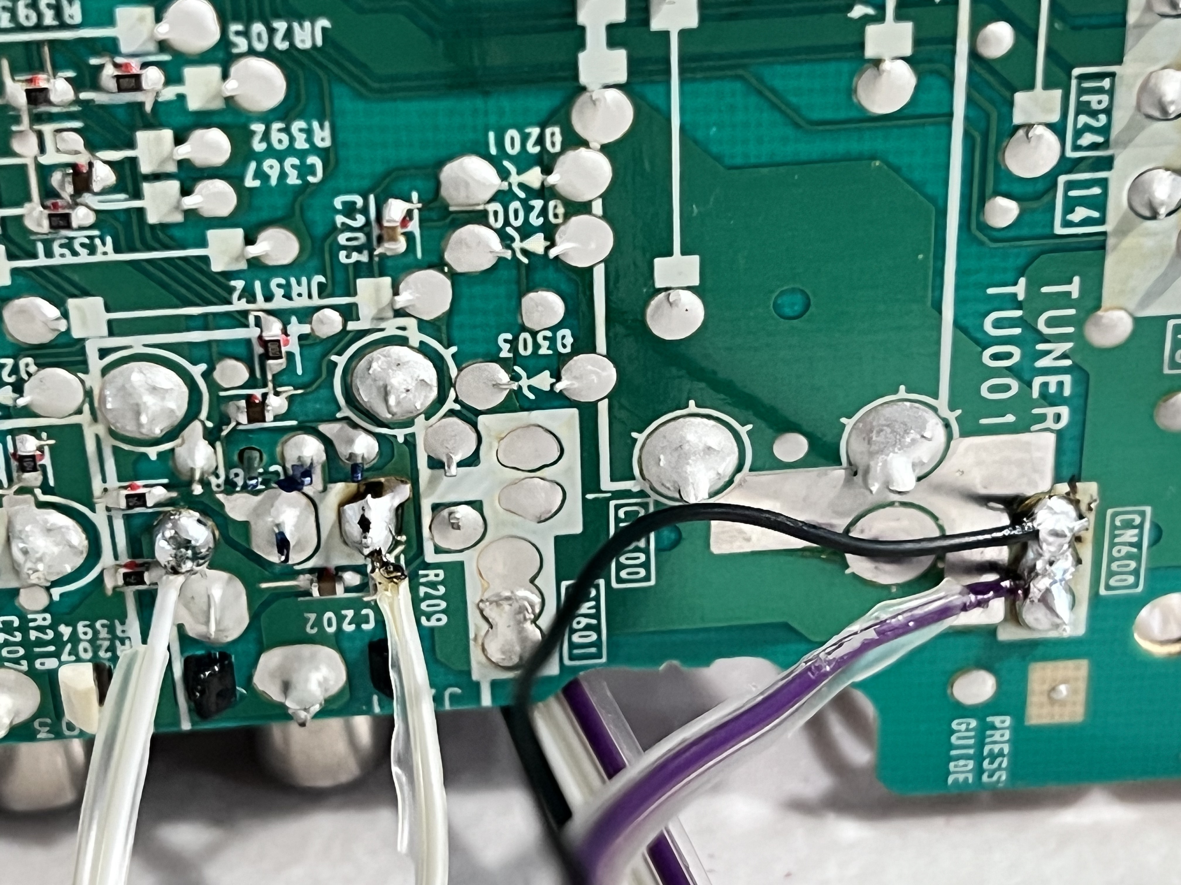
Wire routing
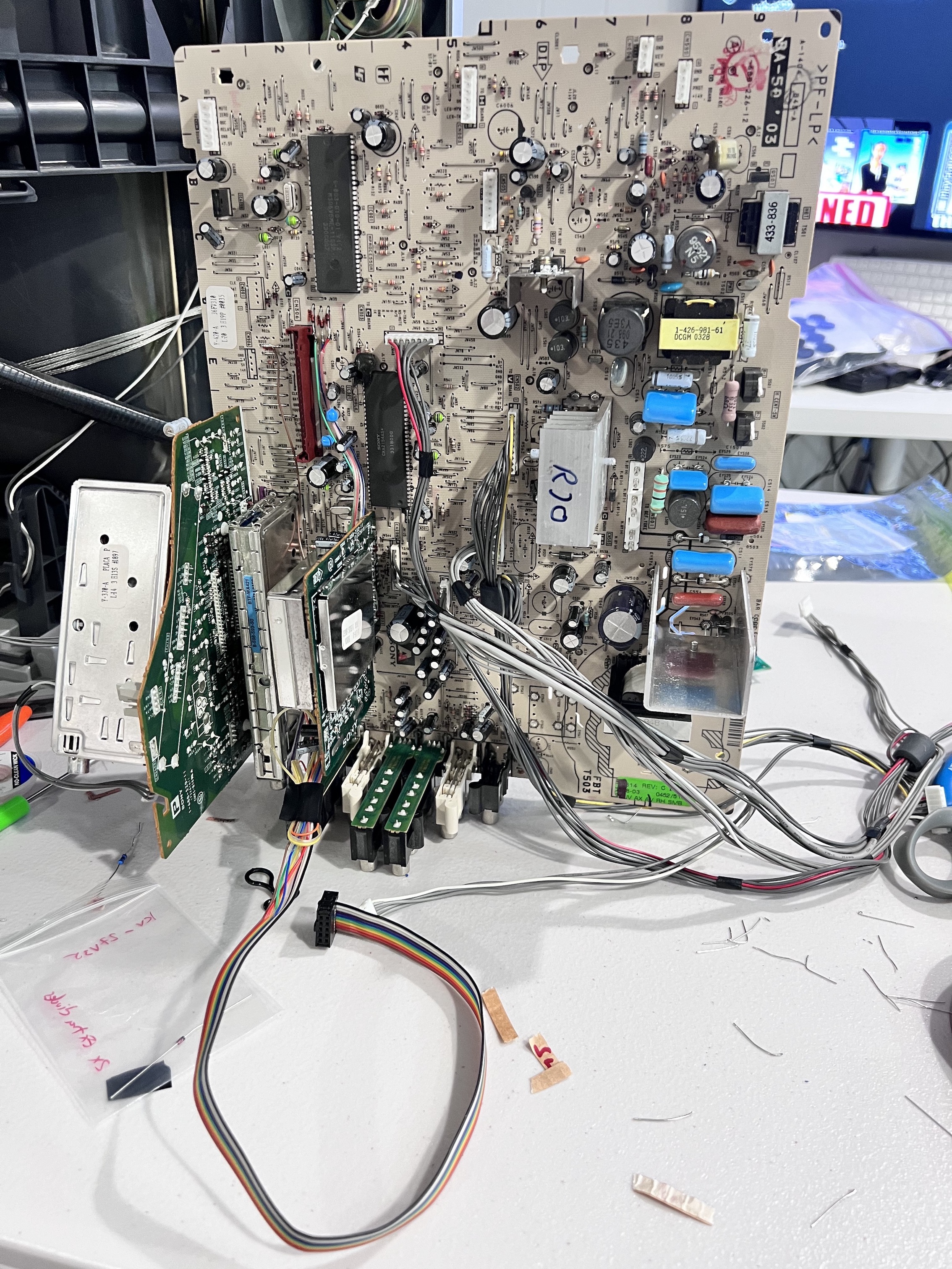
If you are not planning to cut the appropriate traces (this mod did not perform these optional steps) and enable Sync and Audio, you'll have to plug something in the S-Video port to enable luma sync and the red audio RCA port to enable stereo.
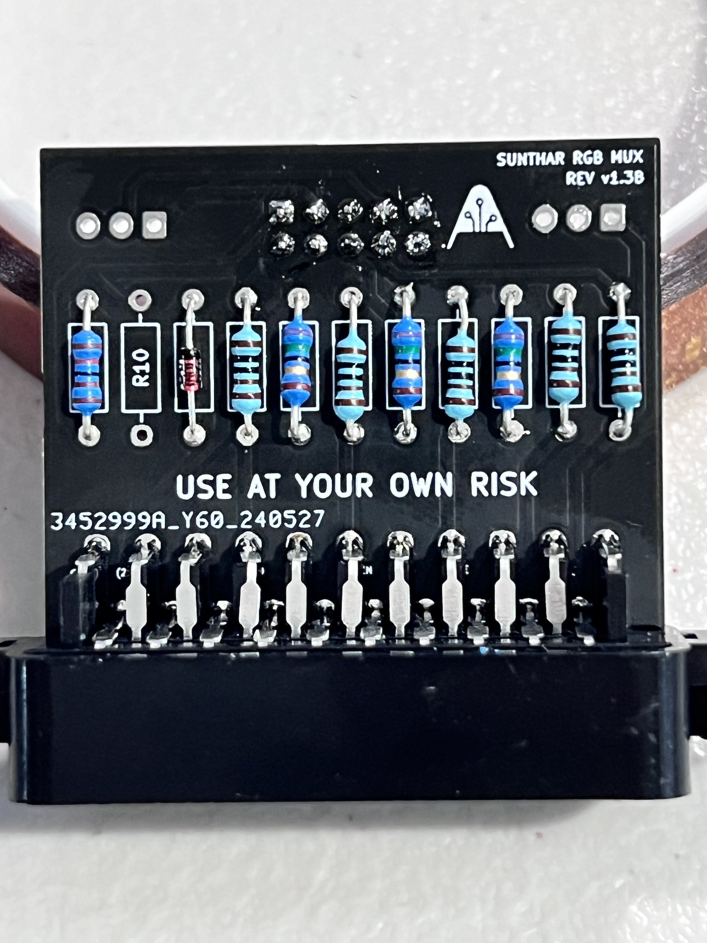
STEP 6: Build your mux board
| Changes on the mux board | KV-27FS100 | KV-36FS100 | KV-32FV310 |
|---|---|---|---|
| CRT RGB inline resistor (on chassis) | 4.7kΩ | 4.7kΩ | 4.7kΩ |
| Removed resistor value (on chassis) | 680Ω | 680Ω | 680Ω |
| Add diodes to RGB lines (optional) | Yes | Yes | Yes |
| Add blanking diode on chassis? | No | No | No |
| RGB termination (R1, R2, R3) | 75Ω | 75Ω | 75Ω |
| RGB inline resistors (R4, R5, R6) | 1kΩ | 1kΩ | 1kΩ |
| Audio LR (R7, R8) | 1kΩ | 1kΩ | 1kΩ |
| Diode (R9) | 1N4148 | 1N4148 | 1N4148 |
| Blanking Ground Resistor (R10) | open | open | open |
| Blanking Resistor (R11) | 1.2kΩ | 1.2kΩ | 1.2kΩ |
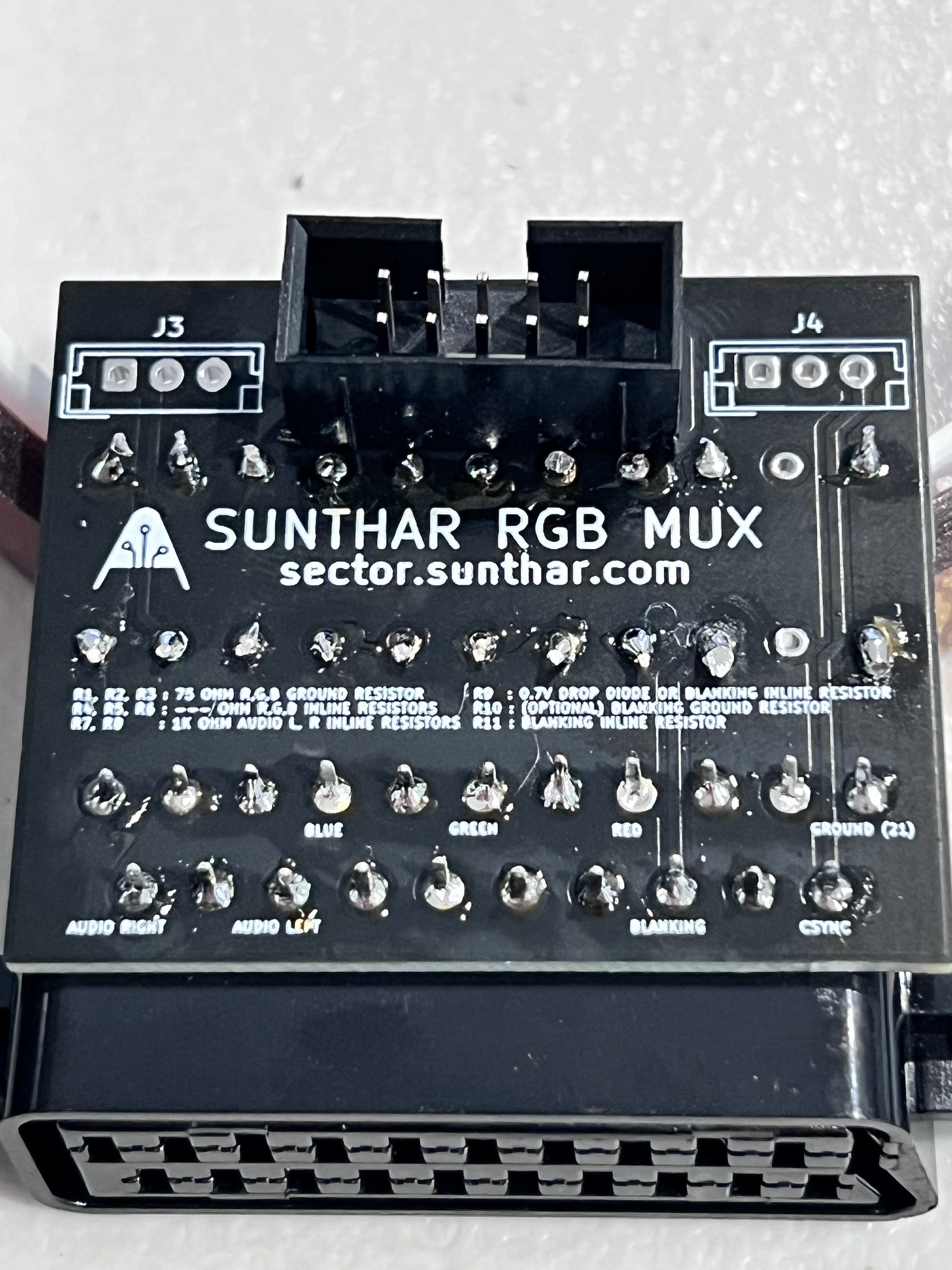
Testing before buttoning up.
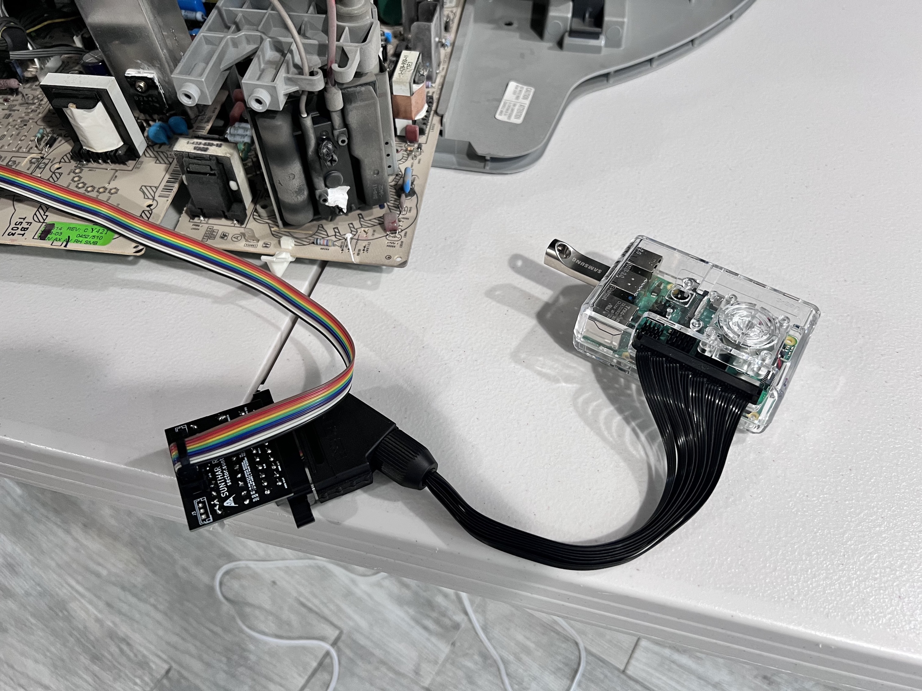
STEP 7: Attach the female SCART connector to TV
Creating a SCART cutout and mounting it is an art. I have a dedicated section for it. How to create and mount a SCART female plug?
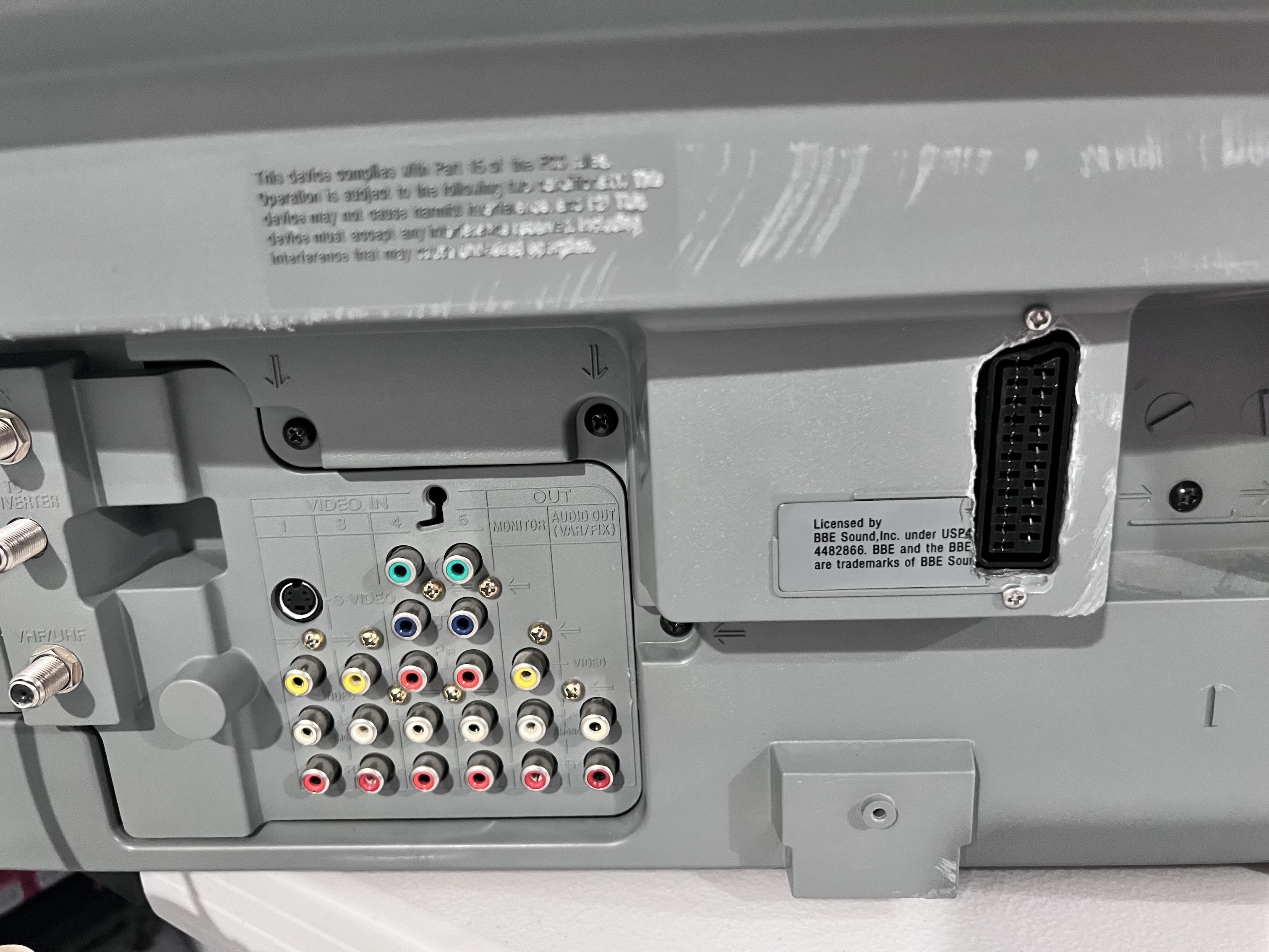
Pictures
Games

TV
