Samsung TXH1973
Samsung TXH1973 CRT RGB mod
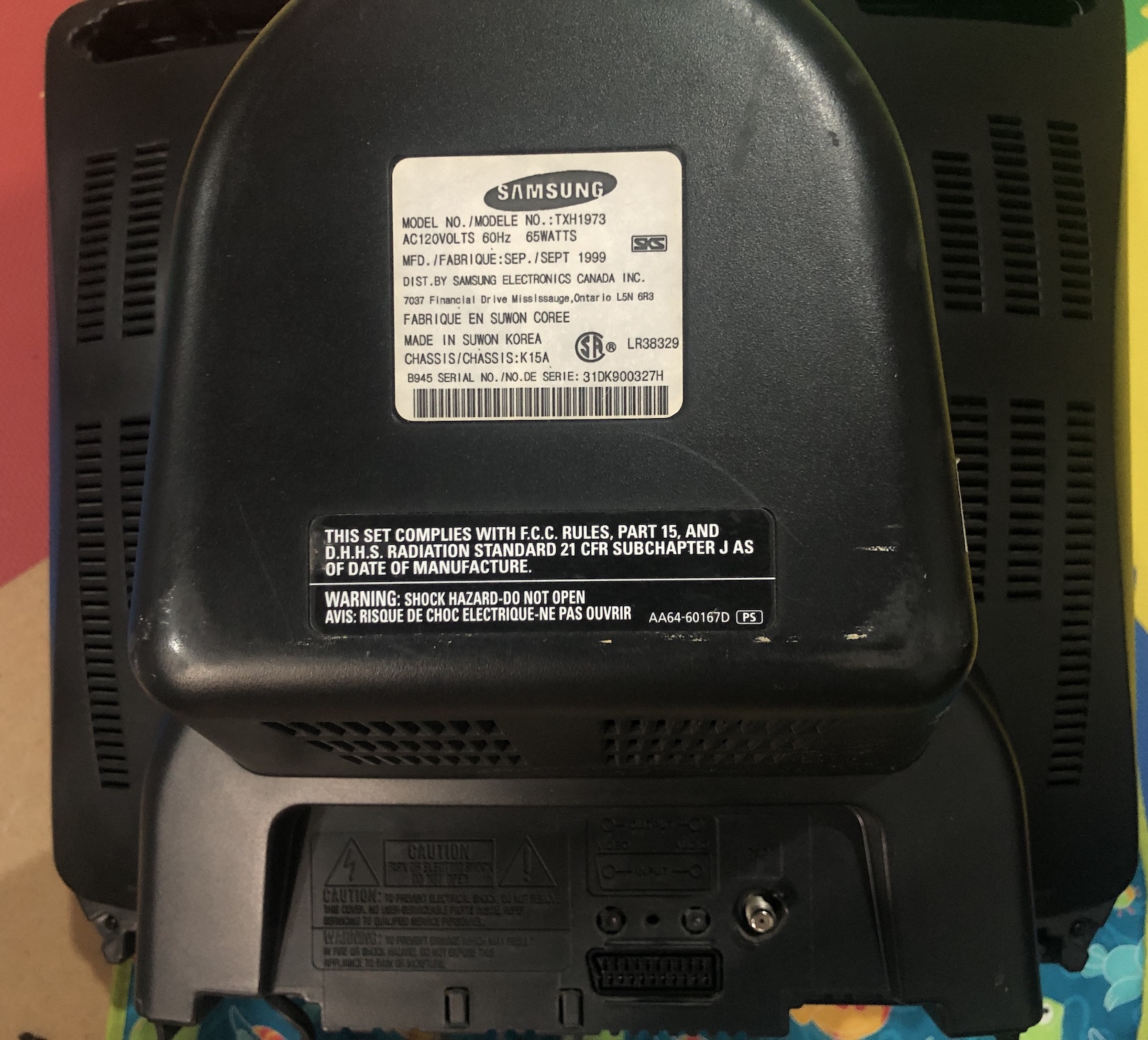
The Samsung TXH1973 is a 19", 4:3 CRT television from the early 2000s. This set is fortunately RGB moddable.
View full CRT details and more mod examples →
This tutorial covers the RGB mod for the Samsung TXH1973 CRT TV. Instructions should be similar for the below CRTs.
- Samsung TXH1370
- Samsung TXH1372
- Samsung TXH1373
- Samsung TXH1386
- Samsung TXH1970
- Samsung TXH1972
- Samsung TXH1973
- Samsung TXH1986
Read below for special instructions on how to improve image contrast and brightness.
Contributors
Thank you to everyone who contributed to this guide:
- Sunthar — contributor, RGB mod and pictures
CRT safety
Caution
You can die doing this! So read carefully! CRT TV is not a toy. Do not open a CRT TV. If you don't have any prior knowledge about handling high voltage devices, this guide is not for you. CRT TV contains high enough voltage (20,000+ V) and current to be deadly, even when it is turned off.
Plan of attack
Manuals and Datasheets
Specs
- Manufactured: Korea ()
- Chassis: K15A
- Tube: Samsung A48KRD82X
- Jungle Chip: Samsung KA2163B
- OSD Chip: Zilog SZM-354ET1
- Screen Size: 19"
Prepare for the mod
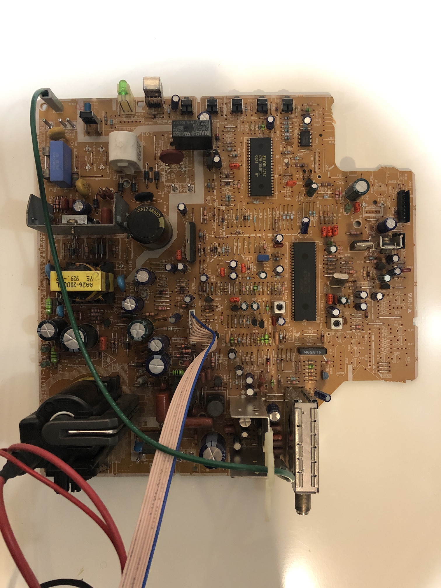
The main board is fairly compact. The main board also comes off the CRT completely, if all the wires are carefully disconnected. This makes it easier to perform the mod. Please make sure to remember or take photos as you disassemble, so that you can reassemble the way it was prior to disassembly.
RGB mux diagram
Prepare the mux diagram. If you are building your own circuit, this diagram should help.
Performing the mod
This CRT was fairly straightforward to mod. You can perform the mod on the board itself and make use of the stock SCART port.
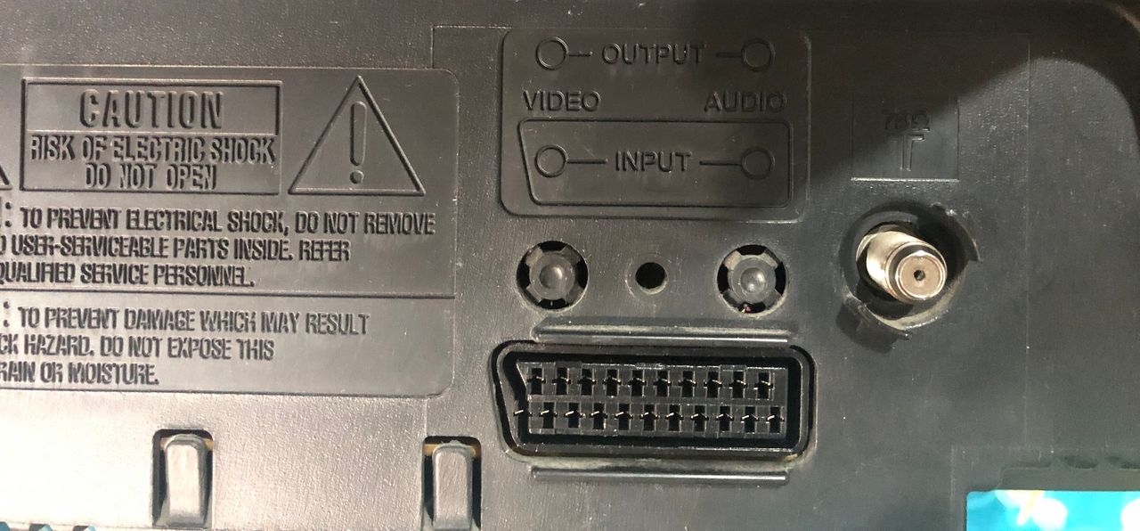
Using the stock SCART port
This CRT comes with a stock AV port that has a SCART cutout. I wanted to utilize this to give this CRT a clean look. Here is how it looks when finished.
You will soon realize this is not as easy as it looks. There isn't that much space on the board to accomodate a SCART plug and the necessary wiring.
How was this achieved?
Remove the existing A/V connector.
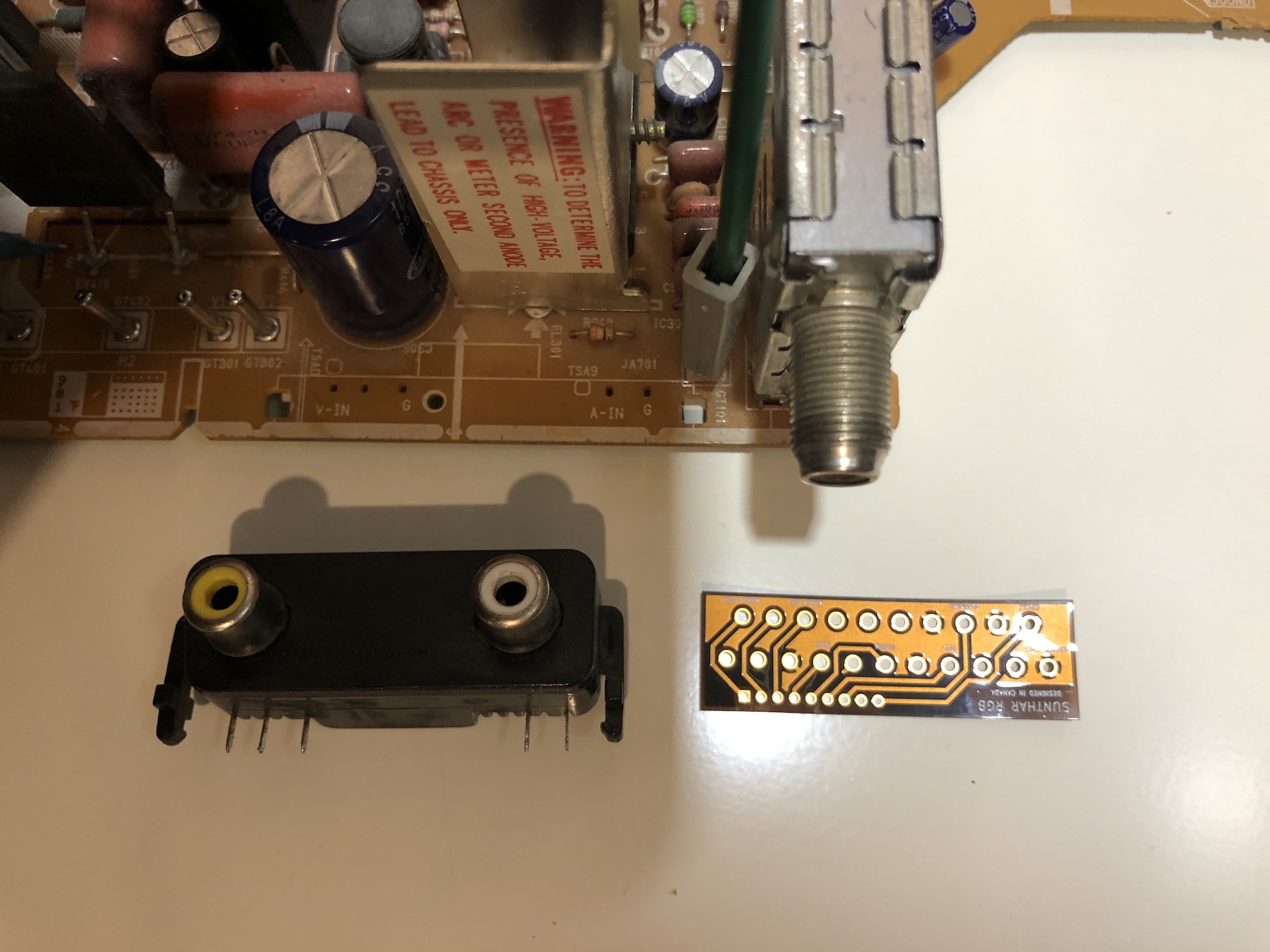
Move this resistor to the bottom of the board to make some space. Compared to TXD1973, I only had to move this one resistor to the bottom of the board.
Create a flexible pcb that grouned the relevant pins together and allowed for routing of the wires. Flexible pcb was used, because there is not much clearance and you want this to be flexible. I'll let the pictures below explain the process.
Prepare the ribbon cable. Make your own flex ribbon board at OSHPark or buy it here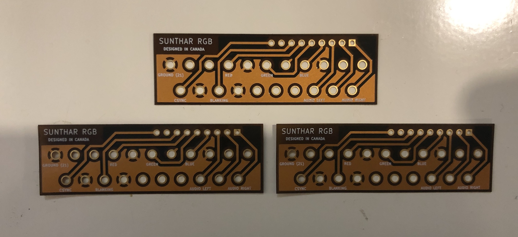
Flush cut the SCART pins and solder to the flexible pcb. 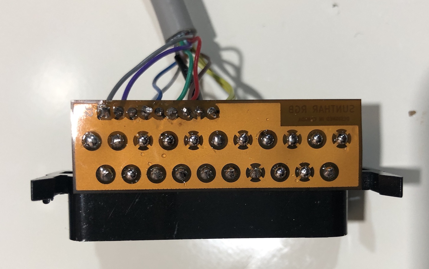
Solder the SCART connector and cable to it. I used an older printer cable. 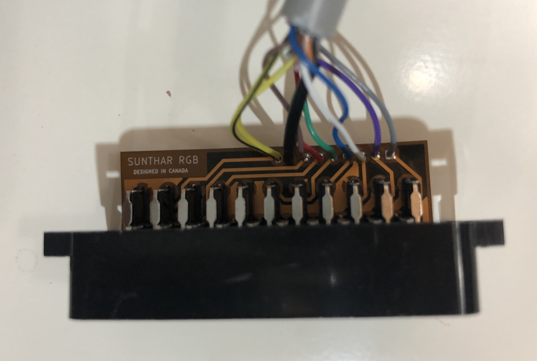
Insulate the SCART adapter with some electrical tape 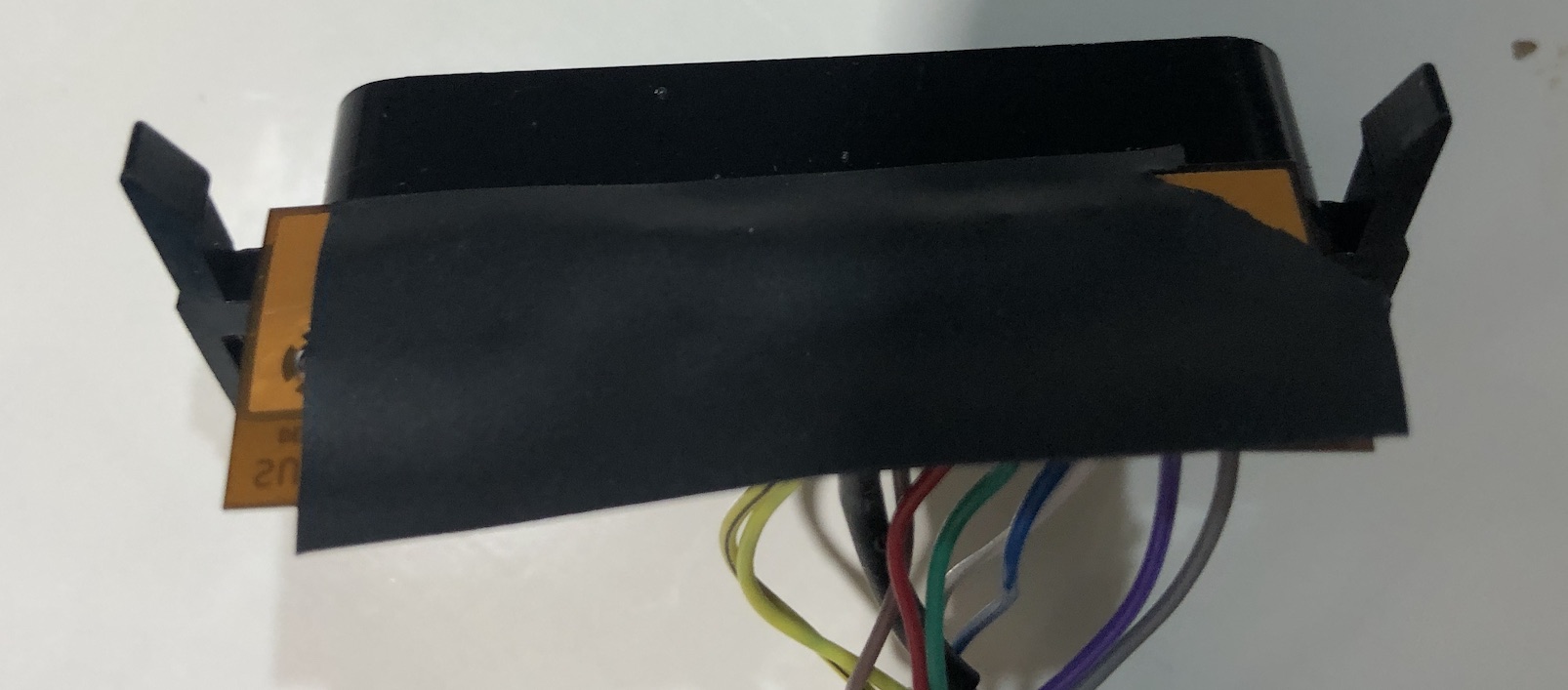
Insulate the main chassis 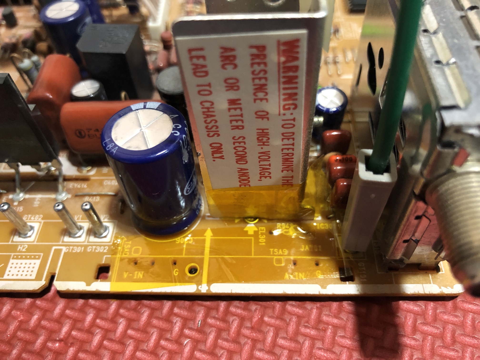
Now place this entiresetup on the board by carefully sliding the flex cable under the large capacitor. A little finesse and you should have the SCART connector with ribbon cable placed in the existing port. 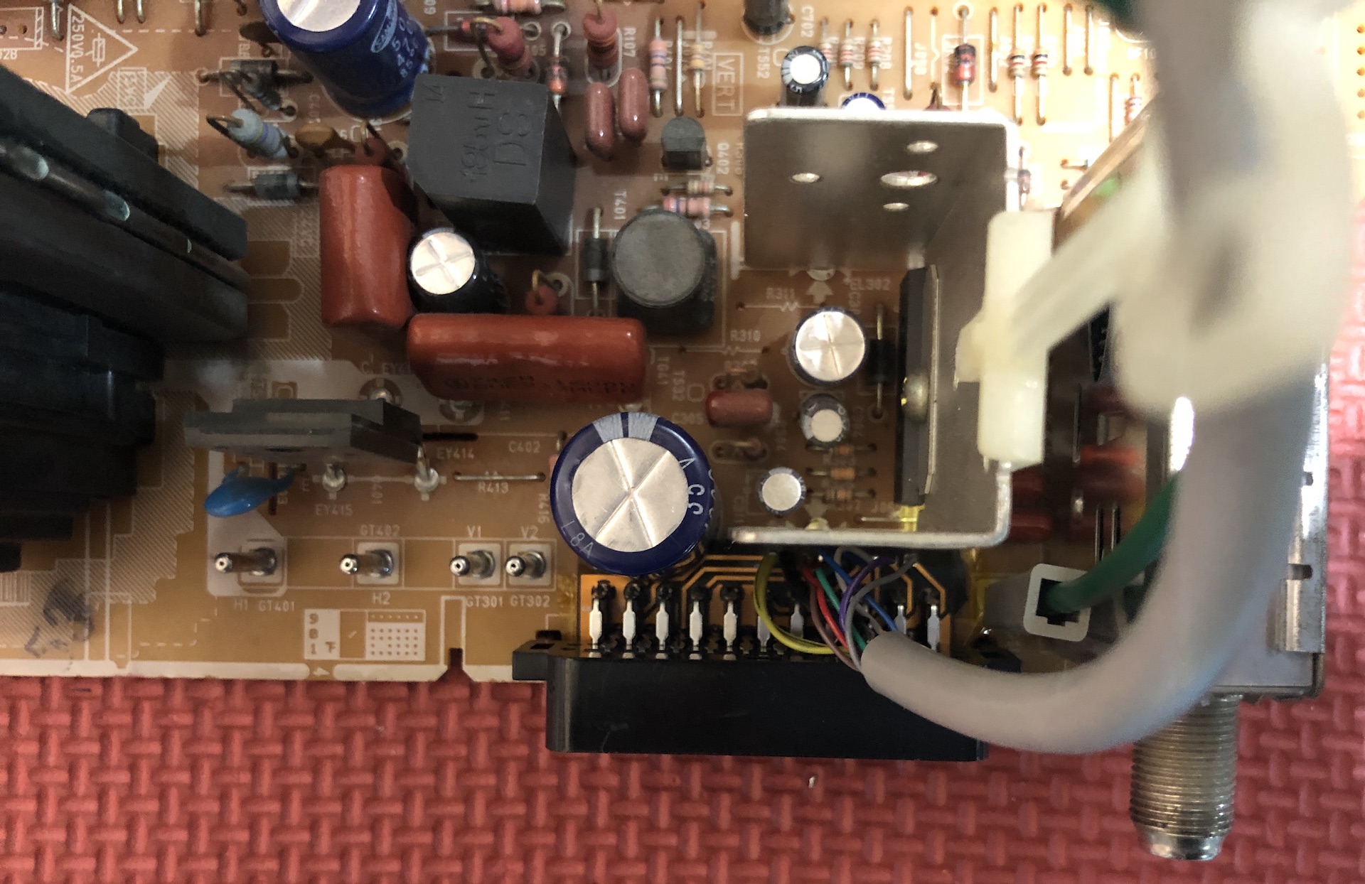
SCART side view 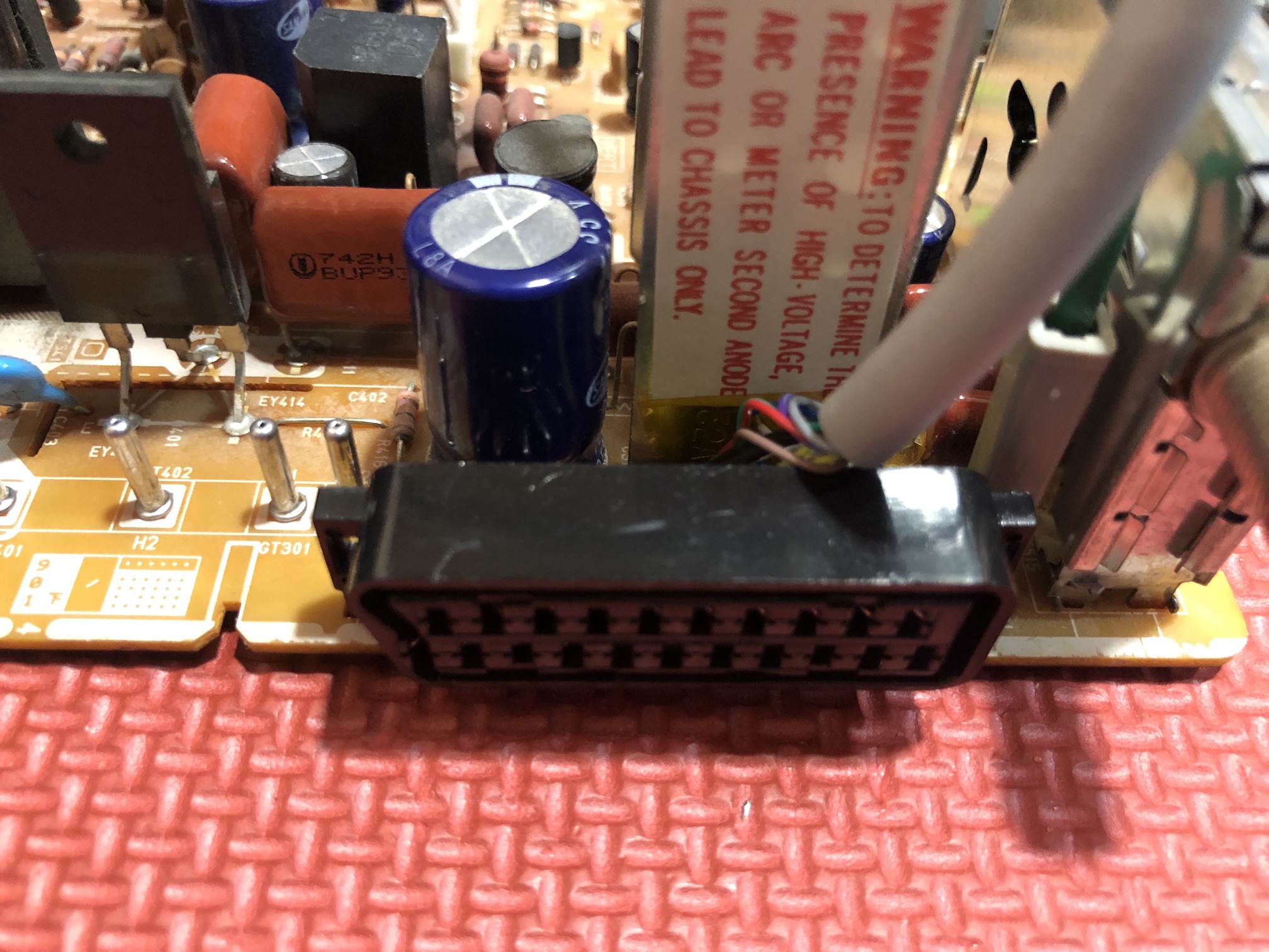
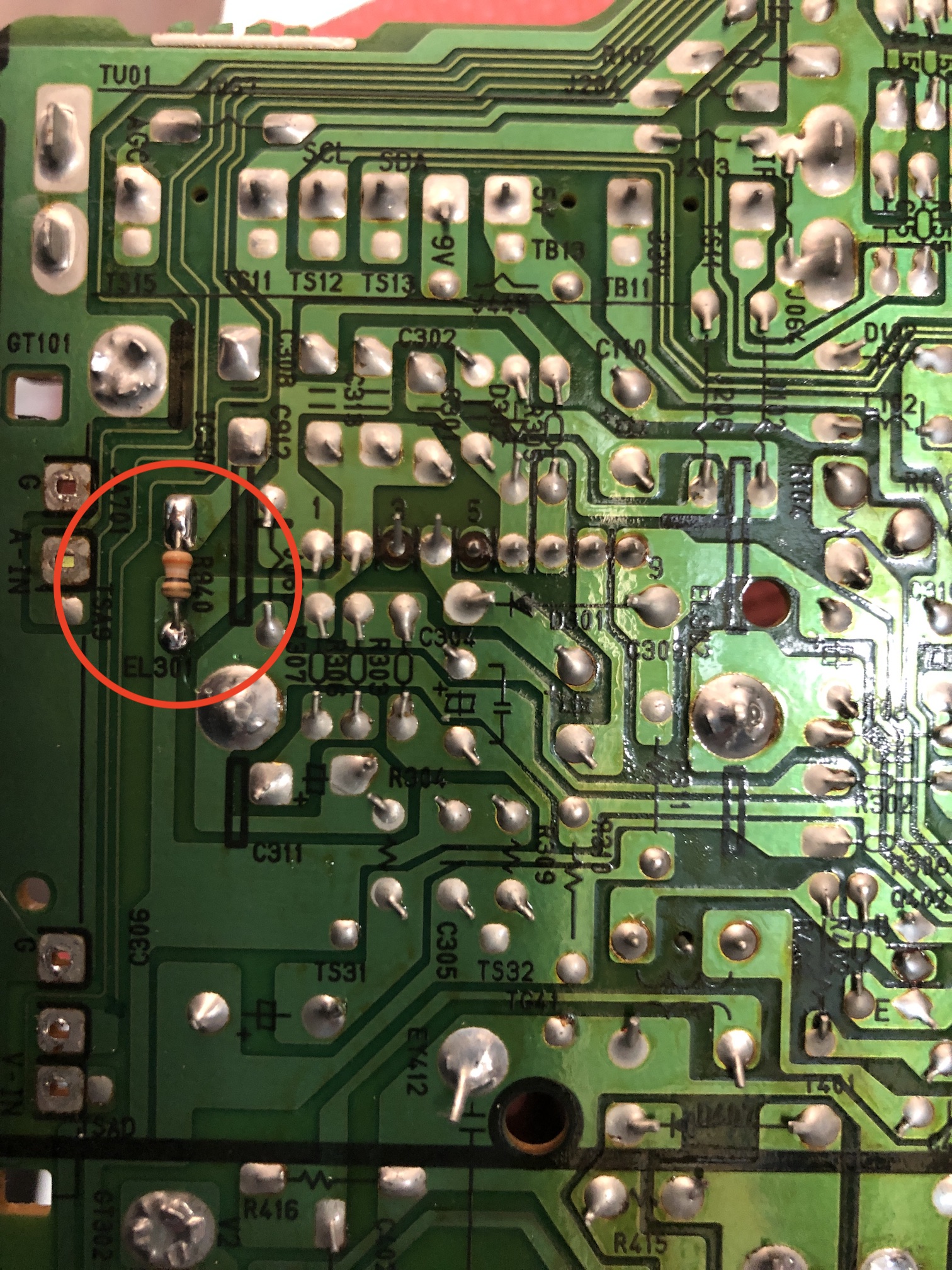
This is the picture of the board before the mod. Areas of interest are highlighted in green. 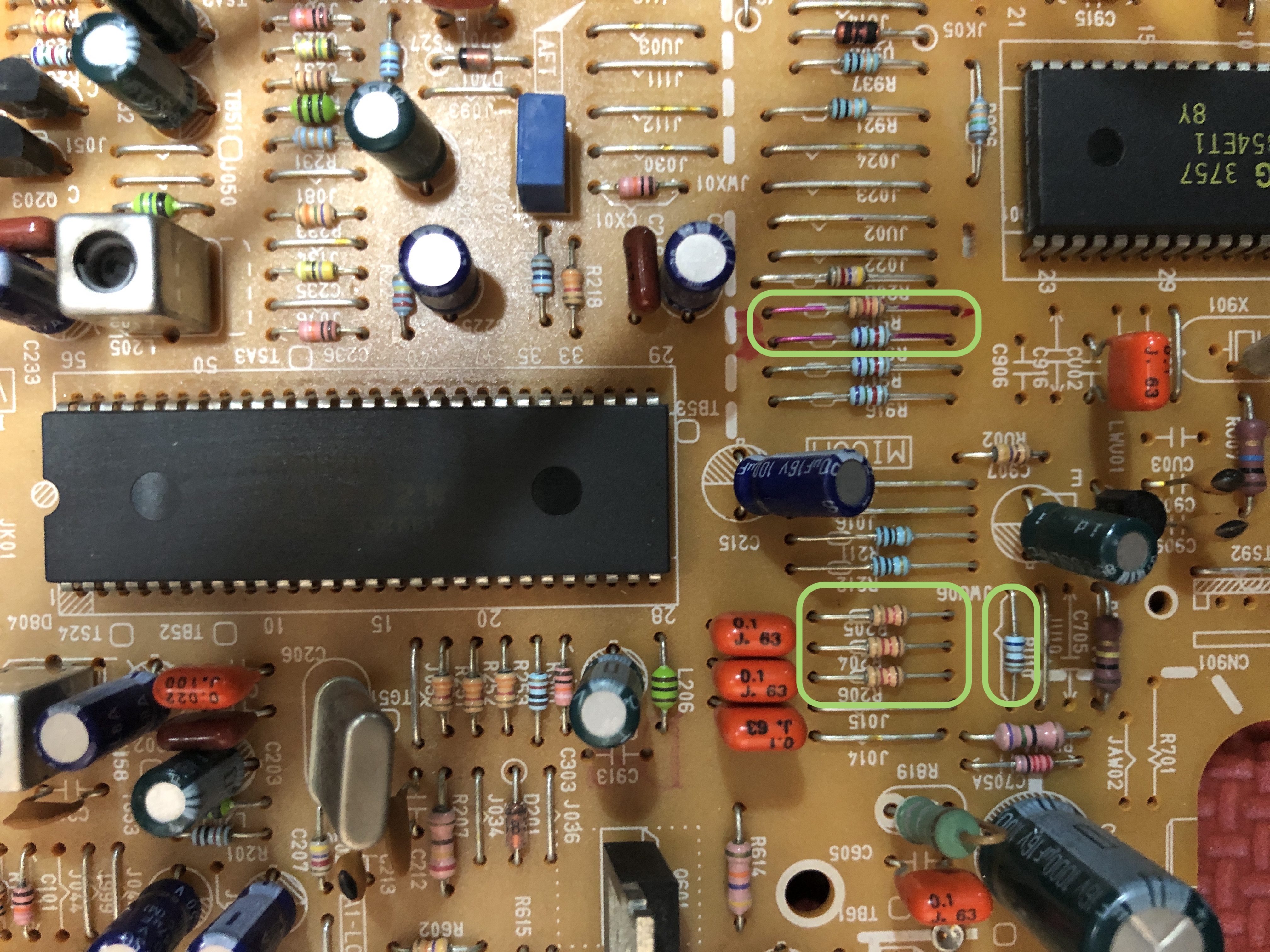
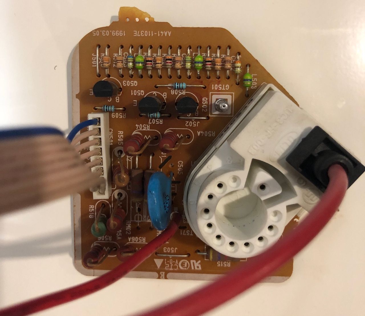
Removed resistors R204, R205, R206. Used the existing vias to connect R, G, B, blanking and ground. RGB wires needs a triangle formed between 220Ω and 1.2 kΩ. 220Ω goes to the grounding side. 1.2kΩ faces the 0.1uF capacitors. Below picture is from TXD1973 (idea is the same) 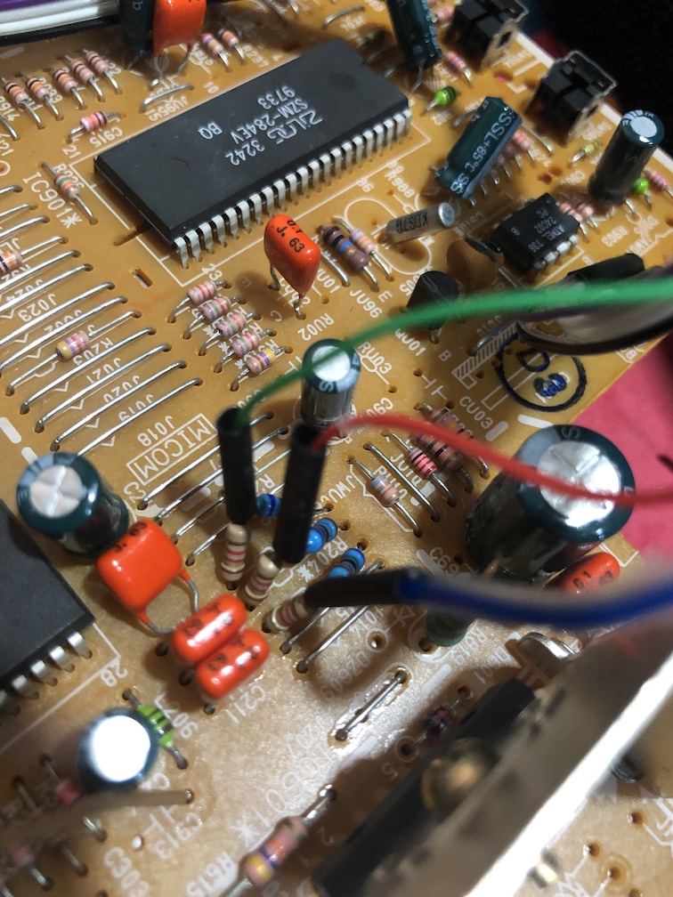
Increasing RGB termination resistance
Tips
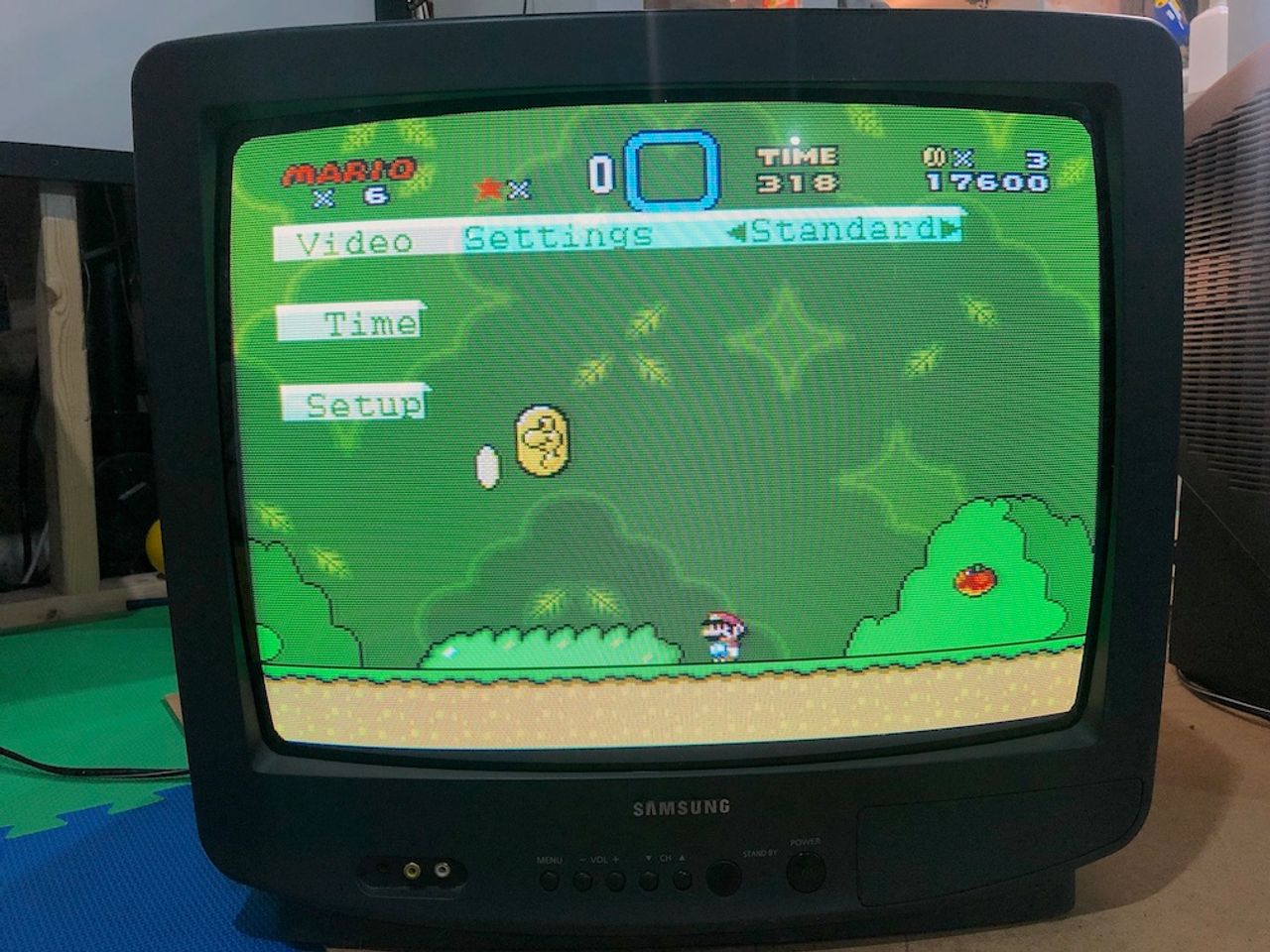
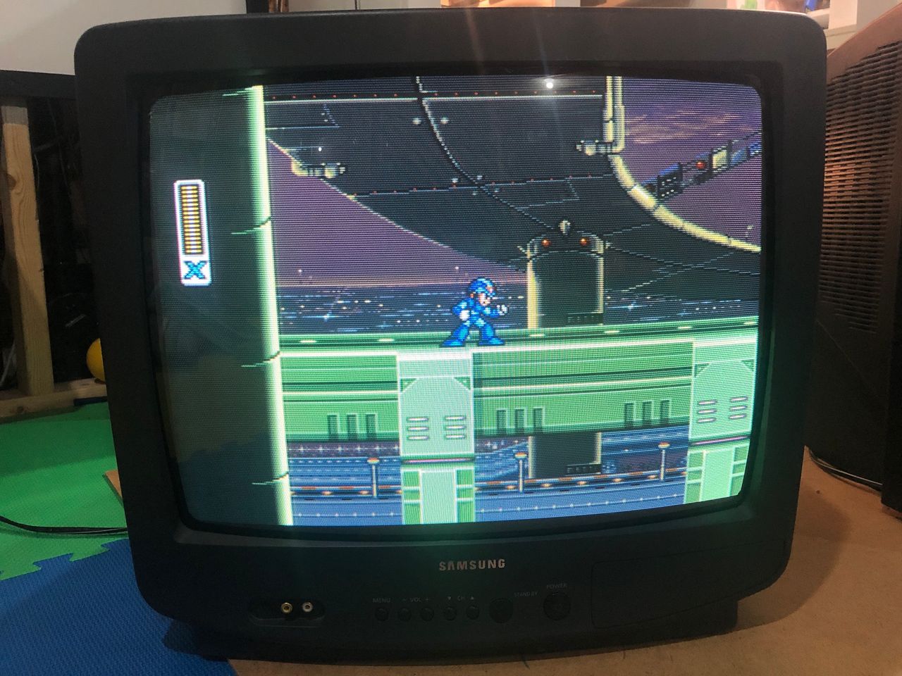
These sets use either a Toshiba or Samsung chroma IC. For noticeably better contrast and brightness, set mux RGB termination (R1–R3) to 180Ω–220Ω instead of the usual 75Ω. On my unit, 220Ω was the sweet spot. The picture went from slightly dark and washed out to punchy and vibrant. The jungle chips listed below are known to benefit from this tweak. It may also help on other chips where modded RGB only passes through the RGB cutoff stage, but results will vary.
I also made an apparatus which I named RGB tuner to sweep through multiple termination values. 220Ω termination seems to hold correct. Not entirely sure why this works, but it works.
Blanking setup needs a bit more work as we want to make sure 5V only goes in one direction. First remove the below blanking trace. We are going to route this through the diode (see schematics) 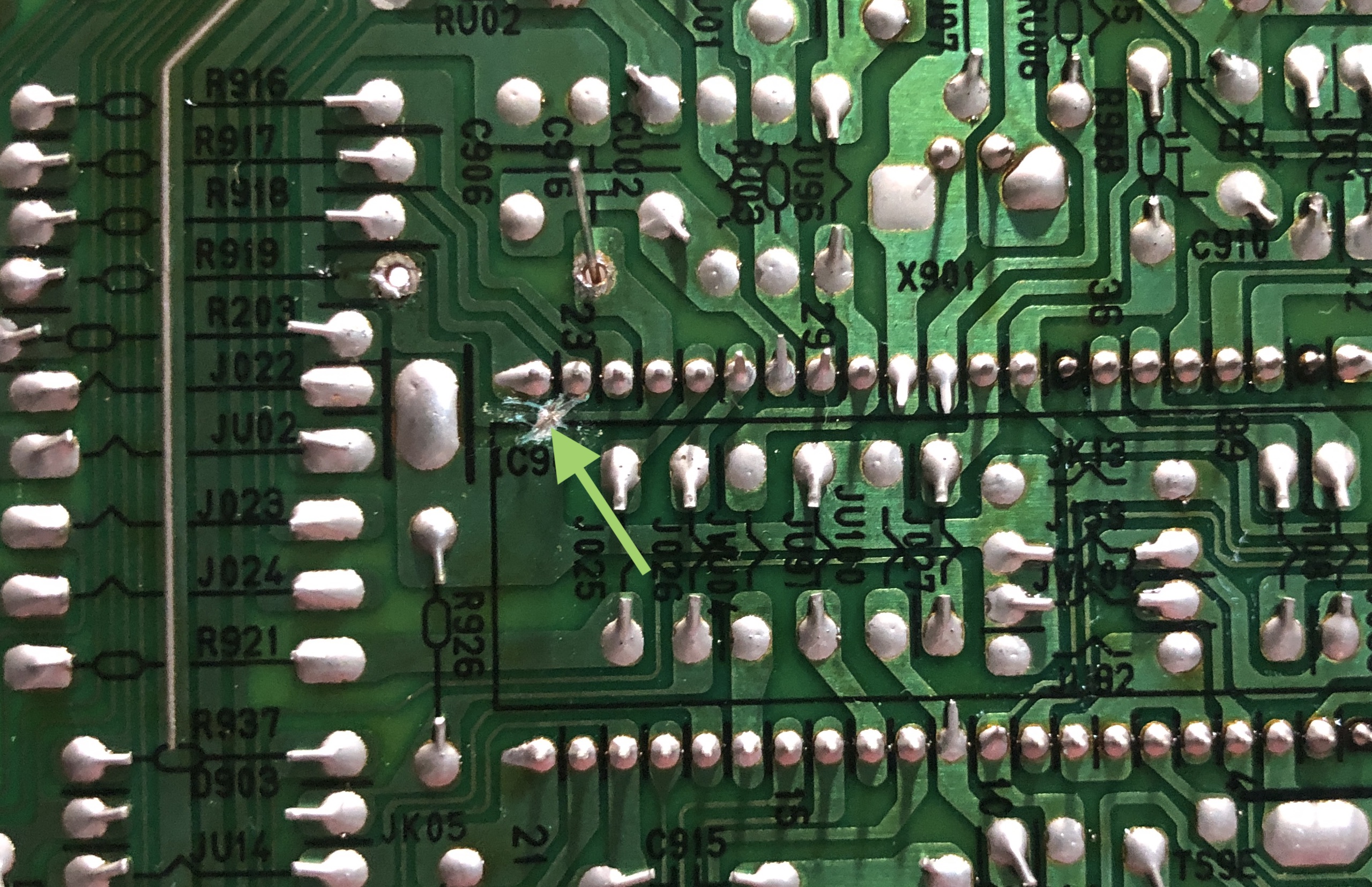
Replace resistor R919 (8.2kΩ) with 6.8kΩ resistor. Setup the diode as seen in the below picture. You will have to squeeze one end of the diode and the resistor through the single via. Pay attention to the direction of the diode. ![]()
Blanking wire from the SCART connector also needs a diode inline. Again, pay attention to the direction of the diode. ![]()
Connect CSYNC to this location. Below picture is from TXD1973 (idea is the same) 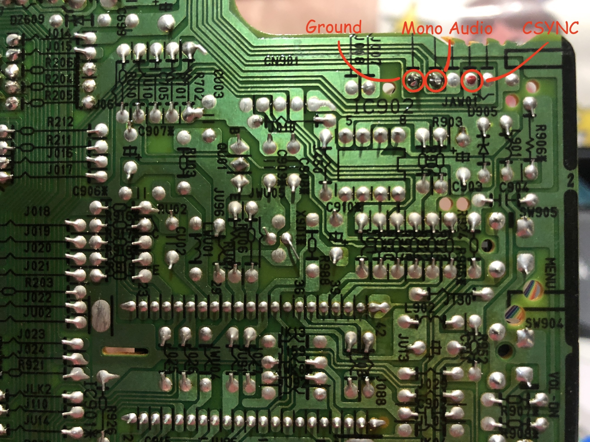
Warning
Use heat shrink tubes to prevent shorting. 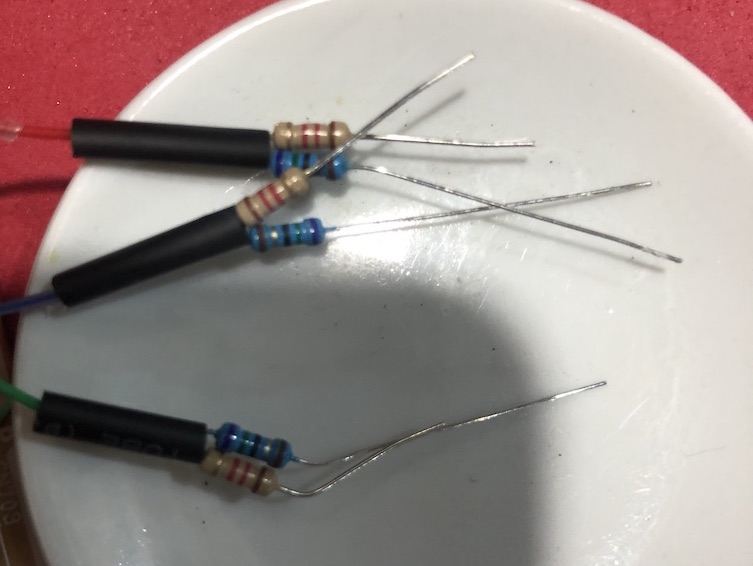
All wired up! 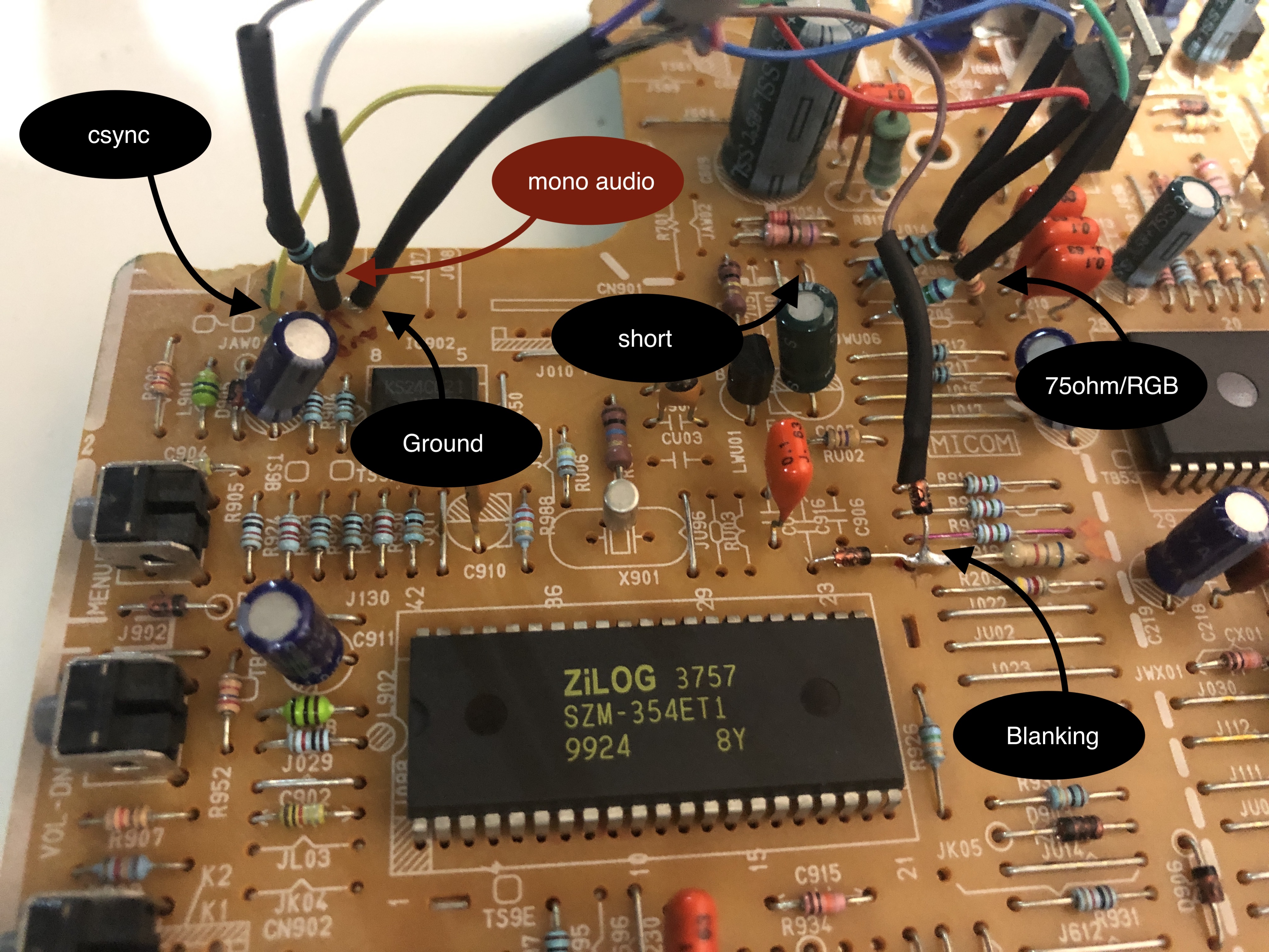
Tips
Connector will be a bit wobbly. However, once the back cover is put back in place and closed up with screws, connector should stay strong. Please be mindful not to push the connector in too tightly and break the connector. Understand the limitations of this mod and possibly use an extension not to damage the SCART connector. SCART closeup. Back cover holds connector in place. 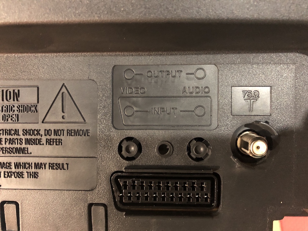
If you want to preserve the A/V inputs in the back and don't want to go through the additional effort of making the SCART port fit in the existing slot, you can also install the SCART port separately using the mux board.
This mod uses the RGB mux board. This is optional, but will make your mod easier and stable. You can also create the circuit presented in the schematics above without the board. Please also checkout the mux calculator to play with your own values.
| Component | Value |
|---|---|
| RGB/OSD inline resistor (chassis) | 7.5kΩ |
| Removed RGB/OSD resistor (chassis) | 1.2kΩ |
| RGB inline diode method (chassis) | Yes |
| 0.1μF caps replaced (chassis) | No |
| RGB termination (R1, R2, R3) | 220Ω |
| RGB inline (R4, R5, R6) | 1.2kΩ |
| Audio LR (R7, R8) | 1kΩ |
| Diode (R9) | 1N4148 |
| Blanking Ground Resistor (R10) | open |
| Blanking Resistor (R11) | 6.8kΩ |
Compatible mux boards:
Service Menu
While in Standby mode, using the remote MUTE > 1 > 8 > 2 > POWER should bring you to the service menu.
Default settings for this CRT 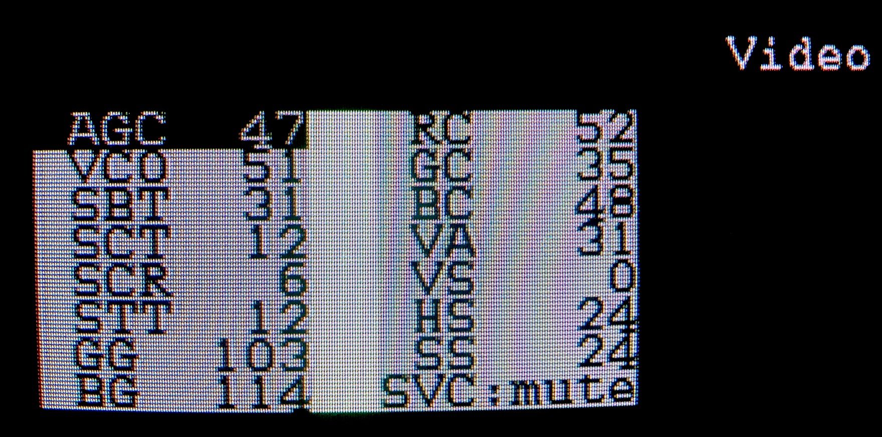
HS - Horizontal Shift was adjusted to center the RGB image
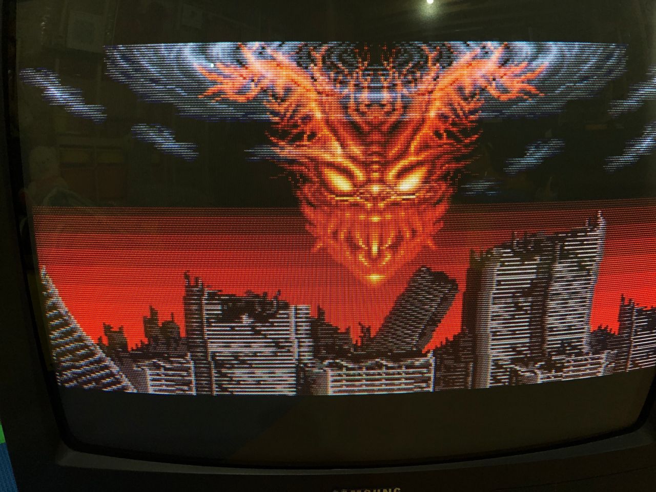
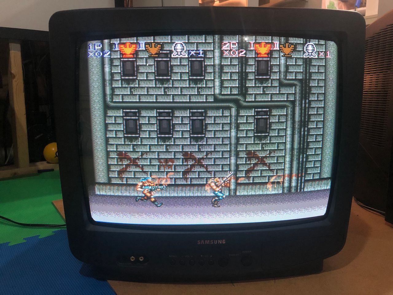
Pictures
Reference Photos