
Sony PVM-14L1
Sony PVM-14L1 CRT RGB mod
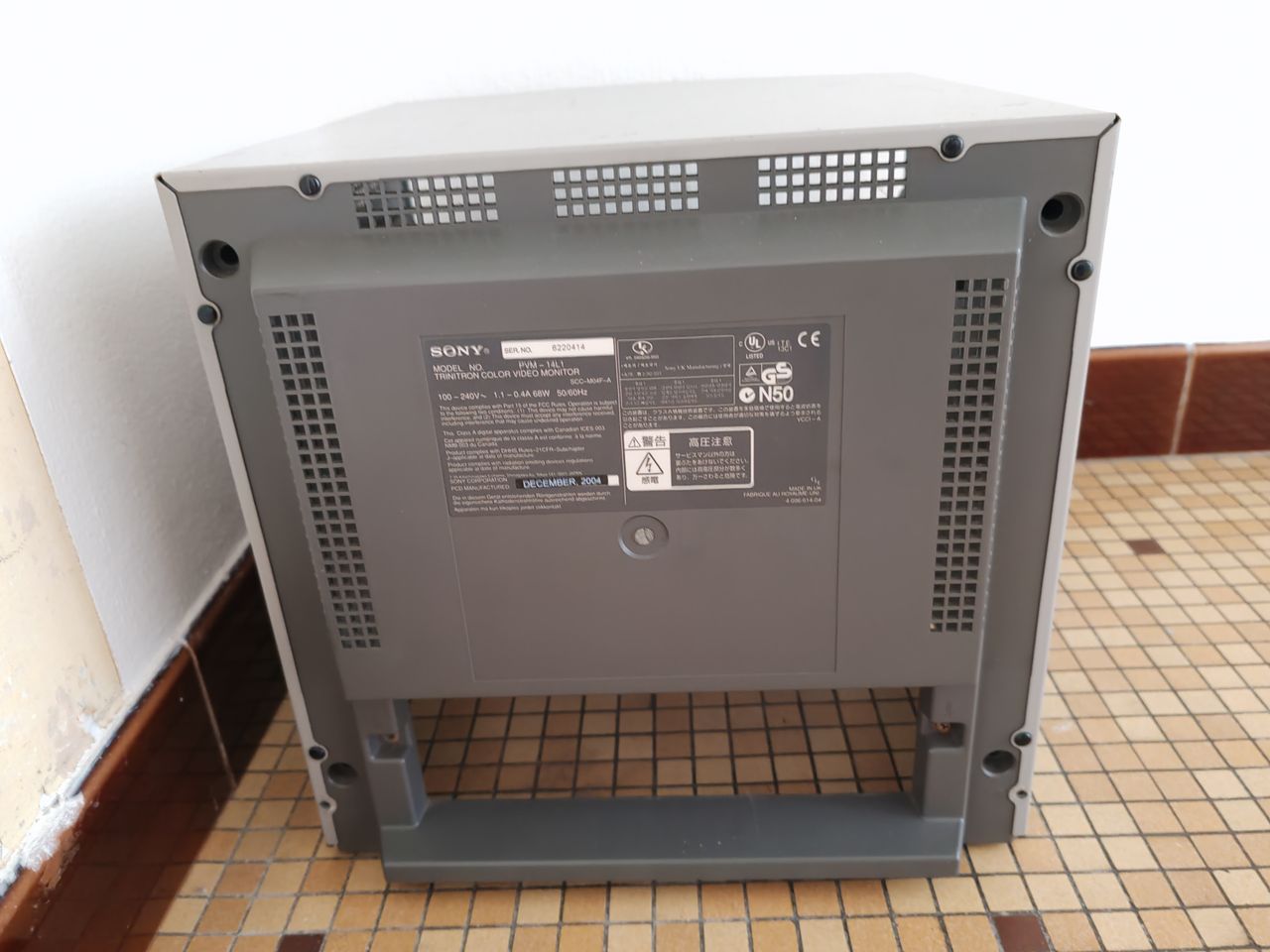
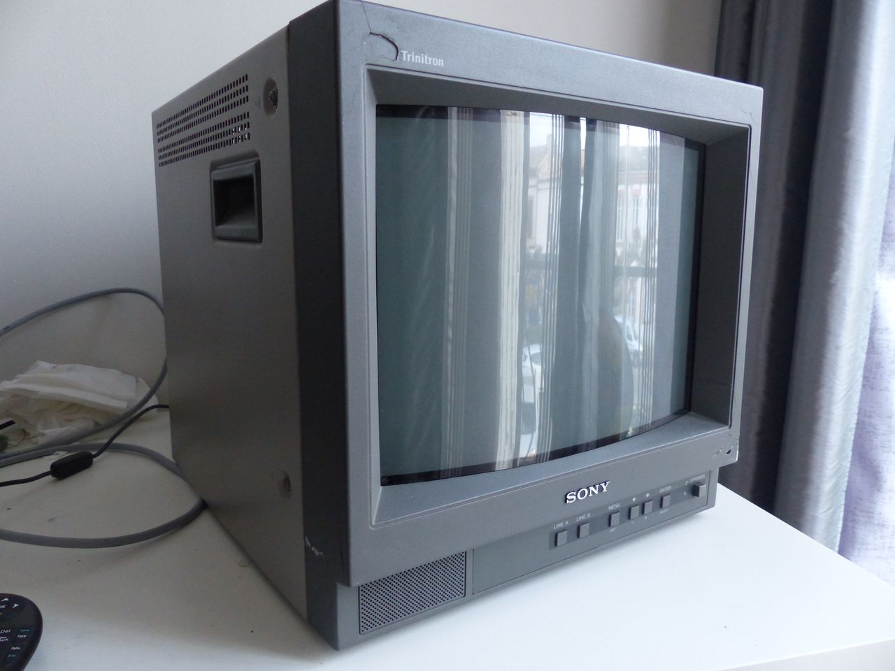
The Sony PVM-14L1 is a 14" professional CRT monitor featuring an aperture grille Trinitron display. Belonging to the final "L" series produced by Sony, it is an entry-level, cost-effective model designed for broadcast, corporate, and security applications. It offers a sharp 600 TV lines of resolution.
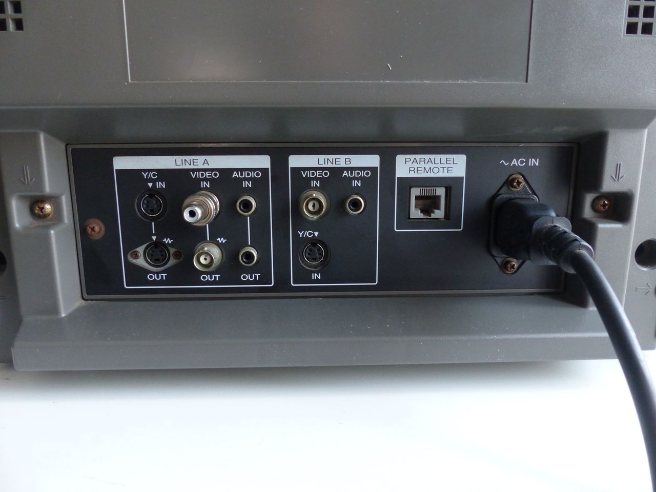
It sports two composite inputs and an S-Video input. Fortunately, this set can be RGB modded.
View full CRT details and more mod examples →
This RGB mod was completed for a PVM-14L1 using the guide for similar model PVM-20L1 written by immerhax https://immerhax.com/?p=573. This mod takes advantage of unused RGB/YUV pins on the jungle chip to allow for direct injection of RGB signals.
Table of Contents
Contributors
Thank you to everyone who contributed to this guide:
- Bertrand POUPEAU — showcase author
- Matt Ross — contributor, CRT specs from CRT Database.
- Immerhax — contributor, Guide to RGB mod
- Andres Ryes — contributor, Guide to RGB mod using sunthar's mux board
CRT safety
Caution
You can die doing this! So read carefully! CRT TV is not a toy. Do not open a CRT TV. If you don't have any prior knowledge about handling high voltage devices, this guide is not for you. CRT TV contains high enough voltage (20,000+ V) and current to be deadly, even when it is turned off.
Plan of attack
Manuals and Datasheets
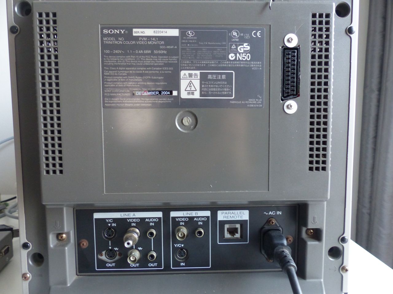
Specs
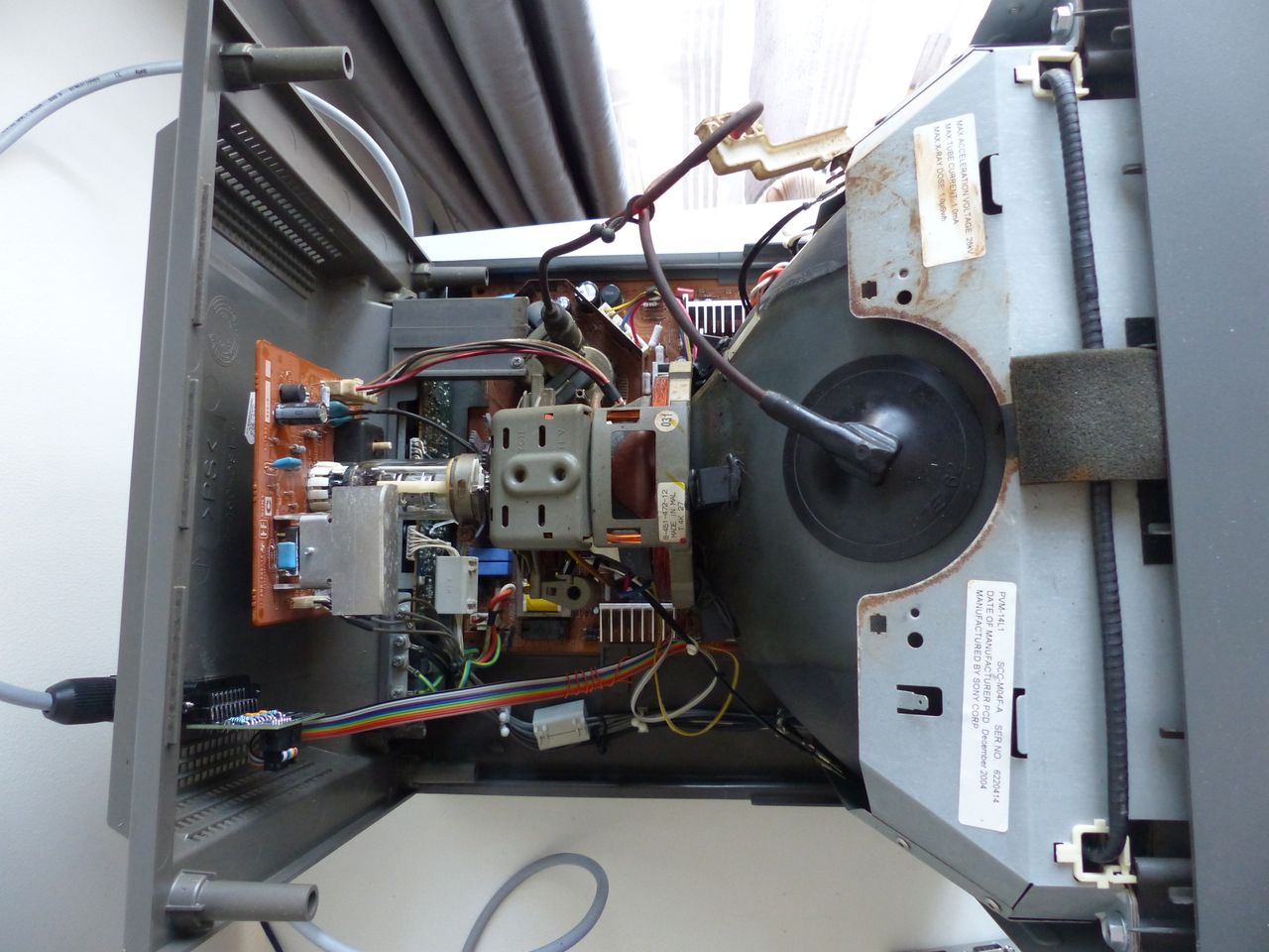
- Year: 2003, 2004
- Format: NTSC, PAL
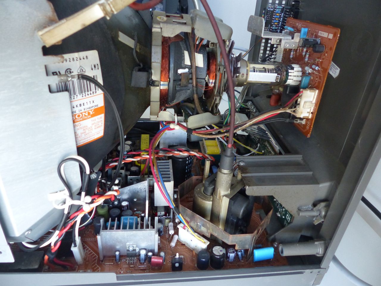
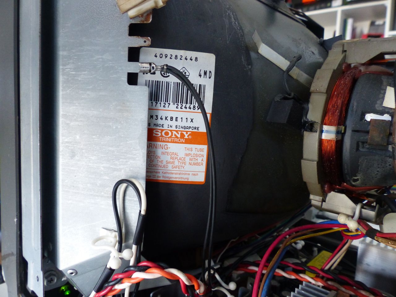
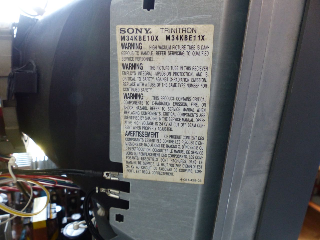
- Tube: Sony Trinitron M34KBE11X
- Jungle Chip: TDA9394H
- Screen Size: 13"
- Power: 68 W
- Weight: 33 lbs
- Inputs: Composite, S-Video
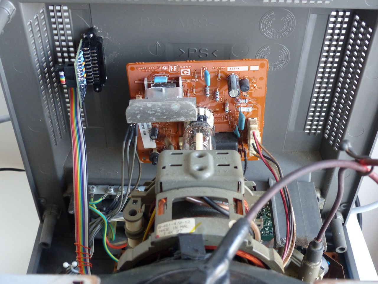
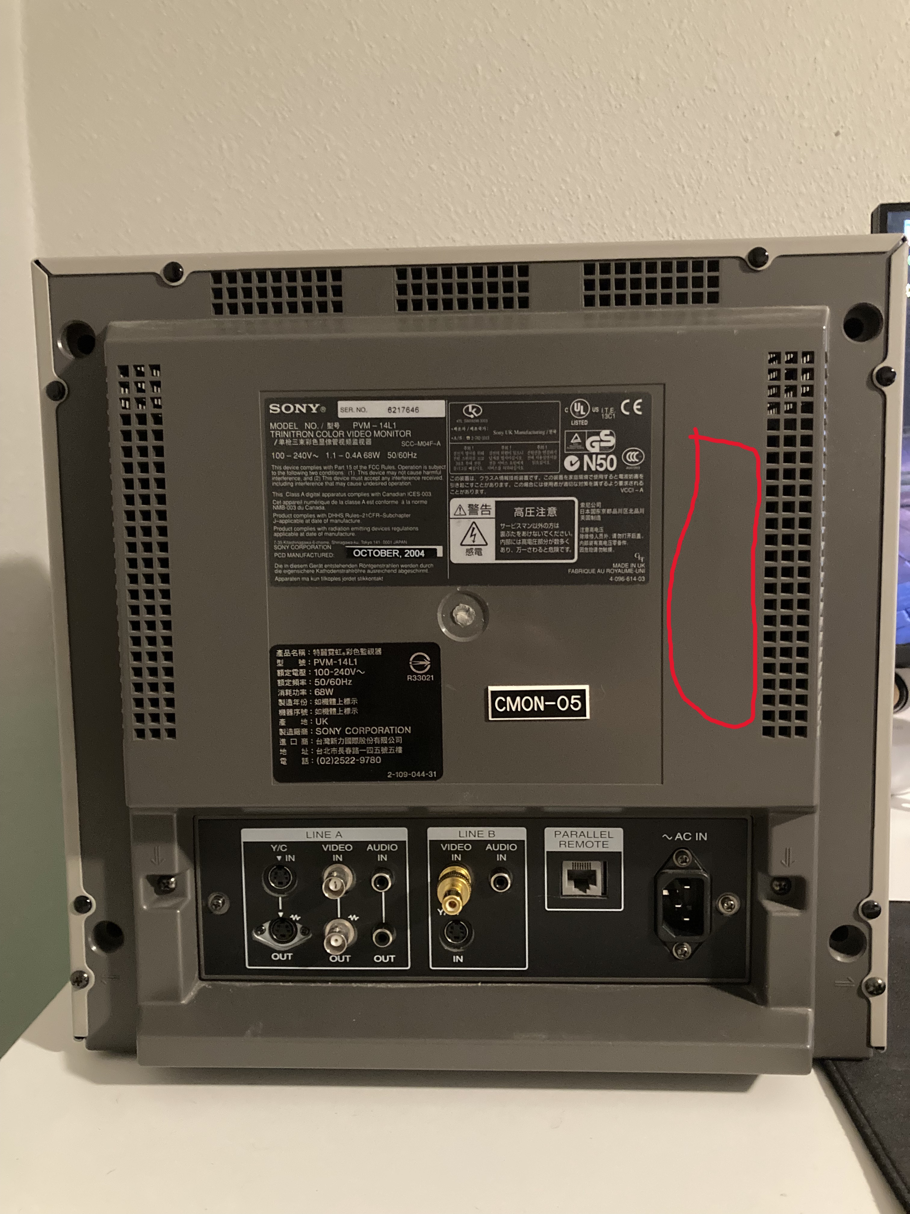 where the SCART port will be eventually attached is marked on the picture above
RGB mux diagram
Prepare the mux diagram. If you are building your own circuit, this diagram should help.
Performing the mod
STEP 1: RGB and blanking
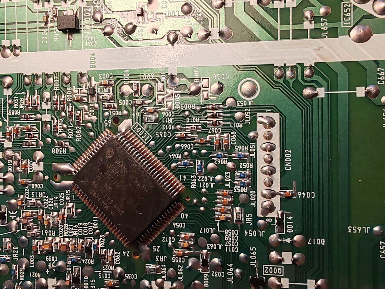
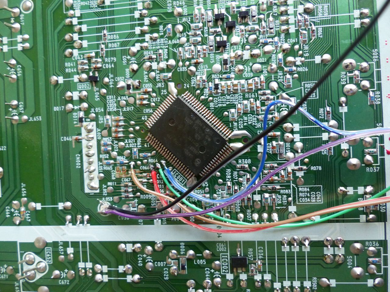
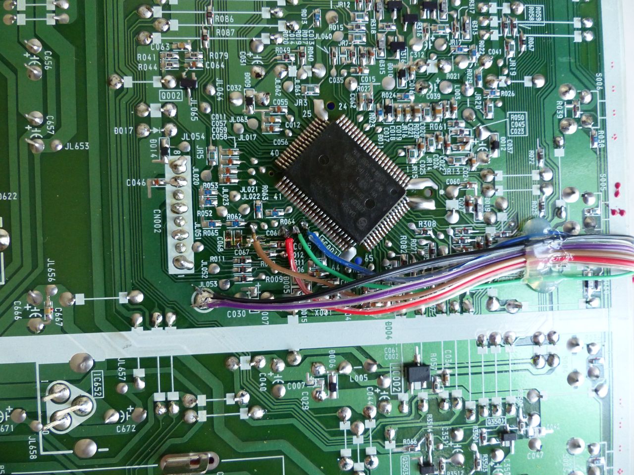
The first step is to open the TV. Remove all necessary screws to remove the cover. Safely discharge the tube. Look at the service manual and remove the connectors on the A board and Q board. The A board is where we will connect our RGB, blanking, common ground, and audio ground lines. The Q board will be where we add our audio left, audio right, and sync lines. Remove the Q board and set it aside. When all necessary connectors are removed, the A board should slide out backwards. Flip the A boards so that the underside is accessible. Direct your attention to the jungle chip. We are interested in pins 50-53.
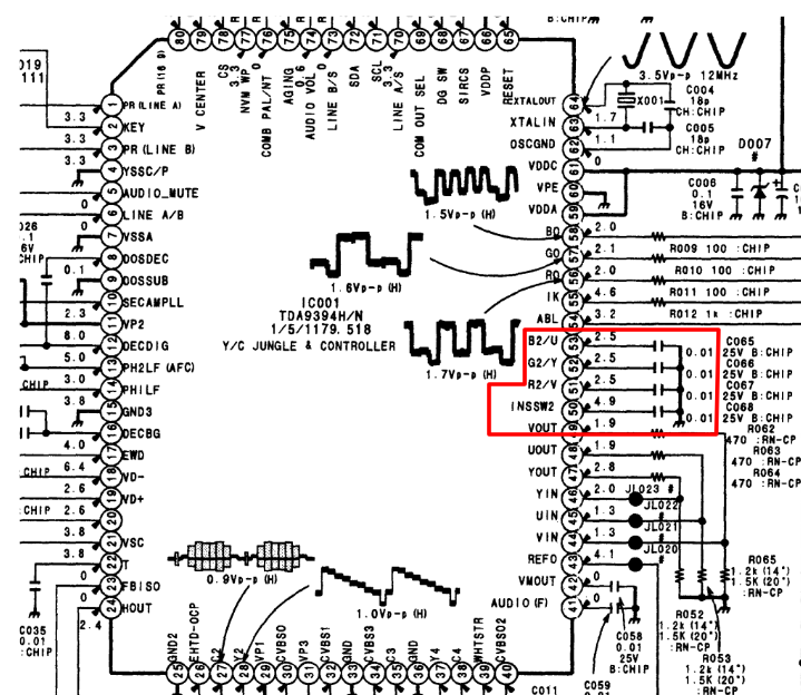
Pin 50, labeled INSSW2 is the blanking line. Pins 51-53 are the RGB lines.
STEP 2: Remove capacitors
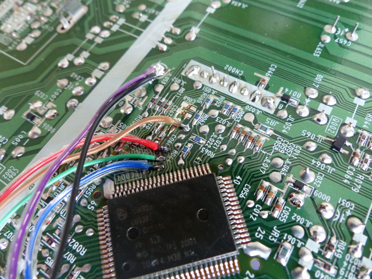
Once you have located these pins, find the nearby capacitors labeled C065, C066, C067, and C068. Remove these four capacitors. The lines for 4 pins of interest have test pads onto which we can solder our injected signals. This will be far easier than soldering onto the pads where the removed capacitors used to be. RGB lines will be passed through 0.1uF capacitors and terminated 75Ω to ground.
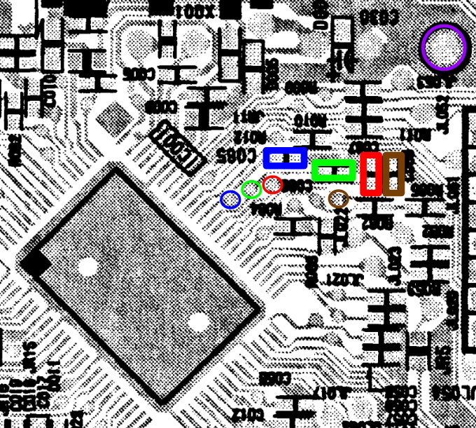
Colored rectangles indicate the capacitors to be removed. Colored circles show locations of test pads to solder R, G, B and blanking lines. Brown is used for the blanking line to be consistent with mux board ribbon cable. The purple circle shows where to solder common ground and audio ground lines.
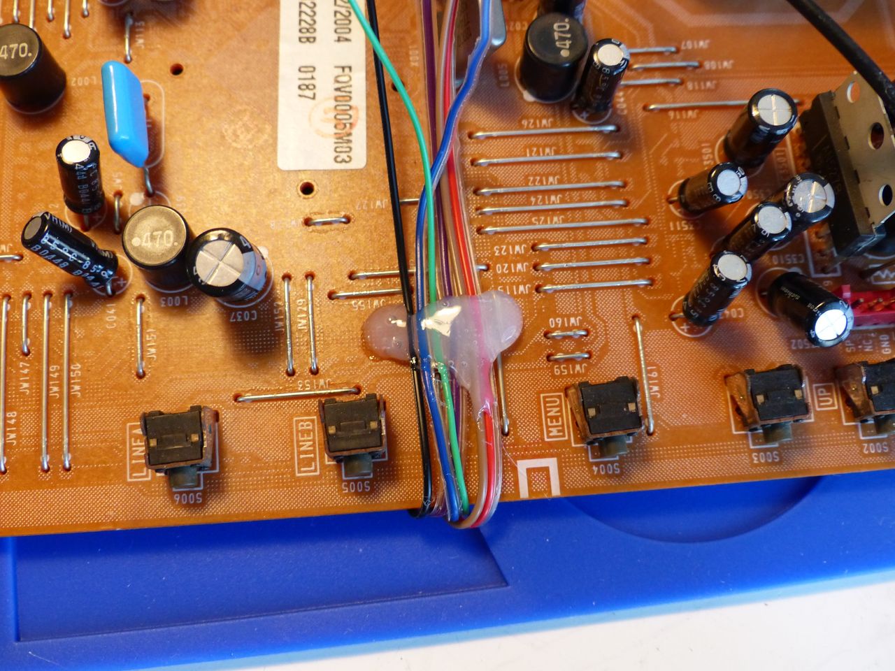
STEP 3: Sync and Audio
The next step is to solder the sync and audio left and audio right lines. We need to Q board that we previously set aside. This TV set has two inputs, Line A and Line B. We will be using the side of the Q board related to Line B.
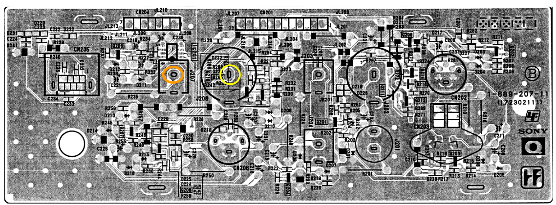
The yellow circle shows the existing connection point for the composite input on Line B. This is where we will solder the sync line. The orange circle is the Audio In connection for Line B. It should be noted that this TV uses mono audio. Therefore, we will solder both the audio left and audio right lines to this point.
STEP 4: Service Menu Settings
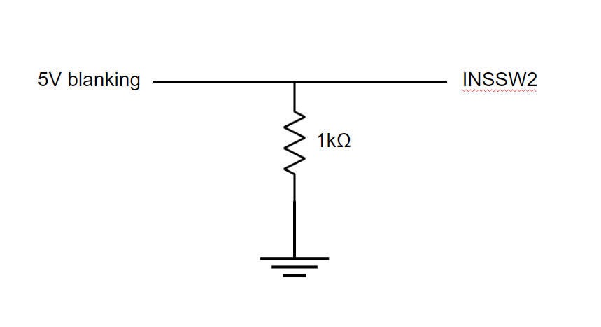
For this RGB mod to function, there are some settings in the service menu that must be changed. Open the service menu by holding the MENU and ENTER buttons on the front for a few seconds. Navigate down to the SYSTEM menu. Here, change the maintenance ID to 111. Return and navigate to the DESIGN menu. On page 2, select CONTROL0. Within the submenu, change IE2 from 0 to 1. Normally, if you were using Y/C input and enabled this option, the screen would turn black. In order to preserve the Y/C functionality of the TV while having IE2 enabled, a pulldown resistor that goes to ground must be connected to the blanking line. This ensures that when nothing is connected to the SCART port, Y/C inputs will still work with IE2 enabled.
Return to the main service menu. Navigate to the ENGINEER submenu. Change COMB FILTER from AUTO to FORCED. This option may only be available on version 1.2 and later of the TV. I personally had version 1.3. I am not sure if the comb filter option exists in any capacity on previous versions. If this setting is left on AUTO, the RGB image will appear only in black and white. Changing to FORCED makes colors appear properly.
Note: A diode was tested on the blanking line, but it caused interference in the form of a wavy purple pattern. As such, the final mux board had no diode installed.
STEP 5: Reassembly Tips
Because of the way the A board slides into place on the plastic frame of the TV, it is not possible to route the newly attached wires from the side. You must route the wires from the underside of the A board towards the front of the TV and back over to the top side of the A board. Do this step very carefully to make sure that you don’t get the wires caught on anything.Then you can guide the wires to the back panel where the SCART port will be mounted.
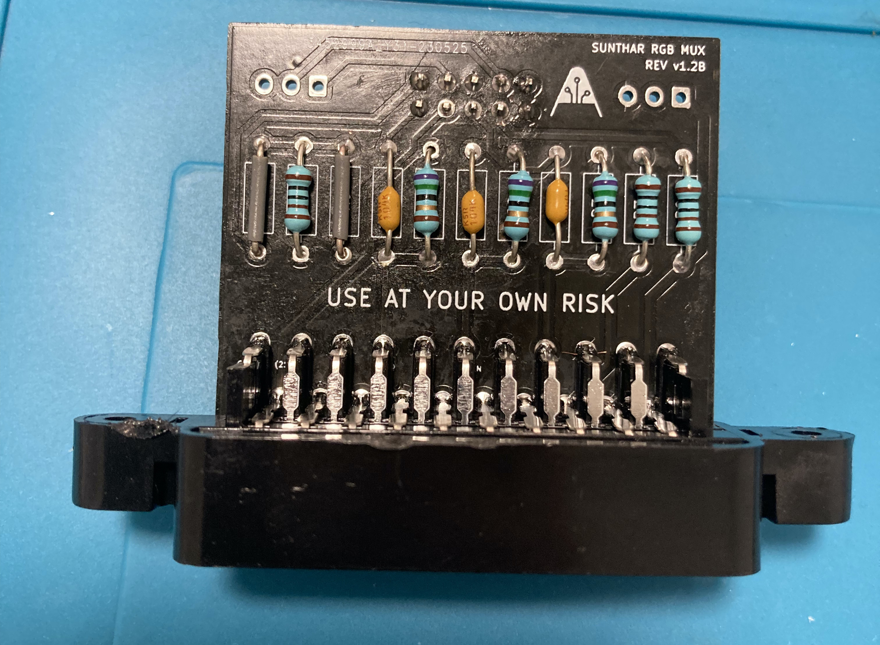
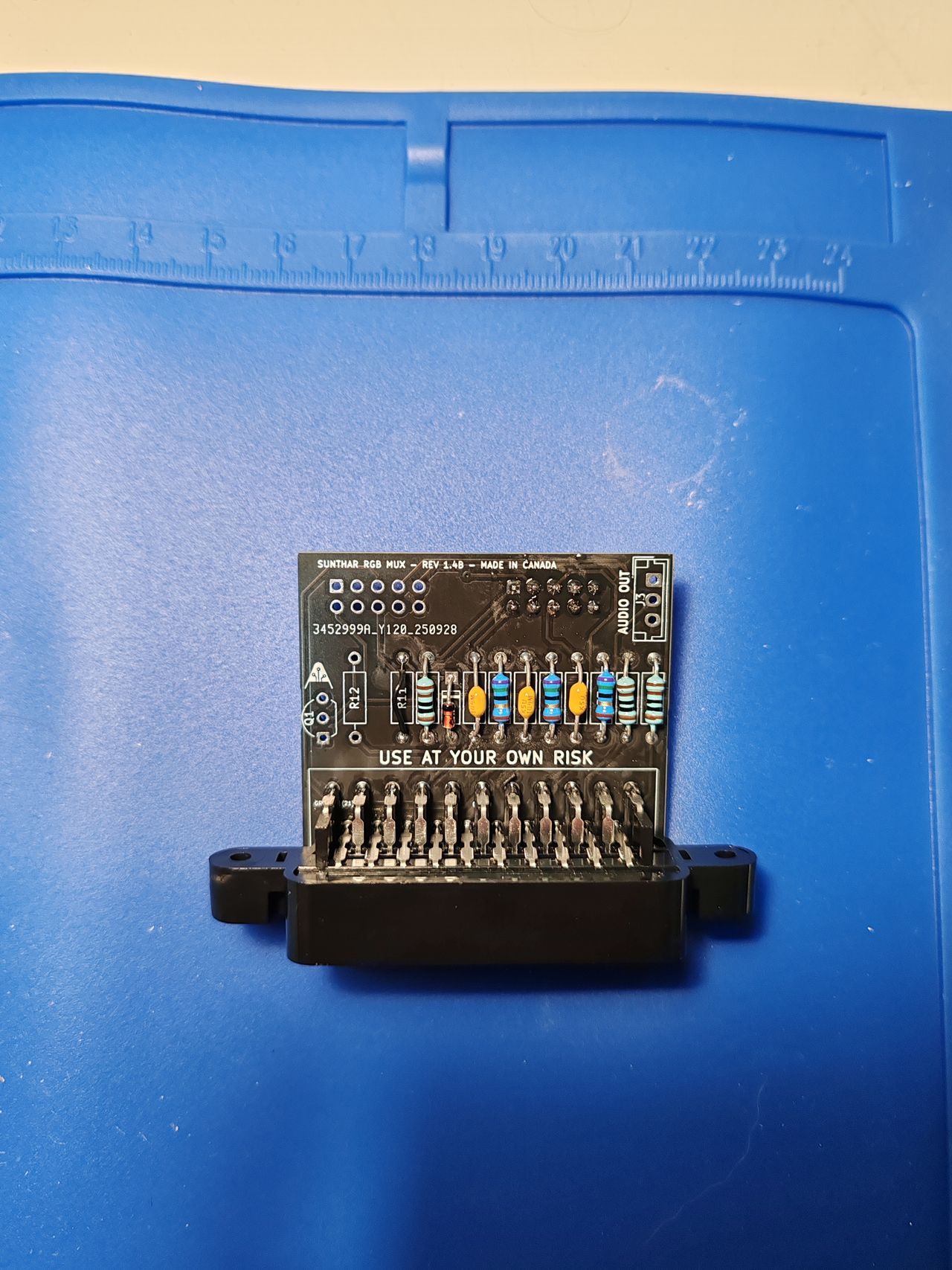
STEP 6: Build your mux board
This mod uses the RGB mux board. This is optional, but will make your mod easier and stable. You can also create the circuit presented in the schematics above without the board. Please also checkout the mux calculator to play with your own values.
| On Sony CRT Chassis | PVM-14L1 |
|---|---|
| 0.1μF caps replaced | No |
| Add diodes on chassis RGB lines? | No |
| Add blanking diode on chassis | No |
| RGB mux board | PVM-14L1 |
|---|---|
| Mux board RGB termination (R1, R2, R3) | 75Ω |
| Mux board Audio LR (R7, R8) | 1kΩ |
| Mux board blanking diode (R9) | 1N4148 |
| Mux board blanking ground resistor (R10) | 1kΩ |
| Mux board blanking resistor (R11) | short |
Back open 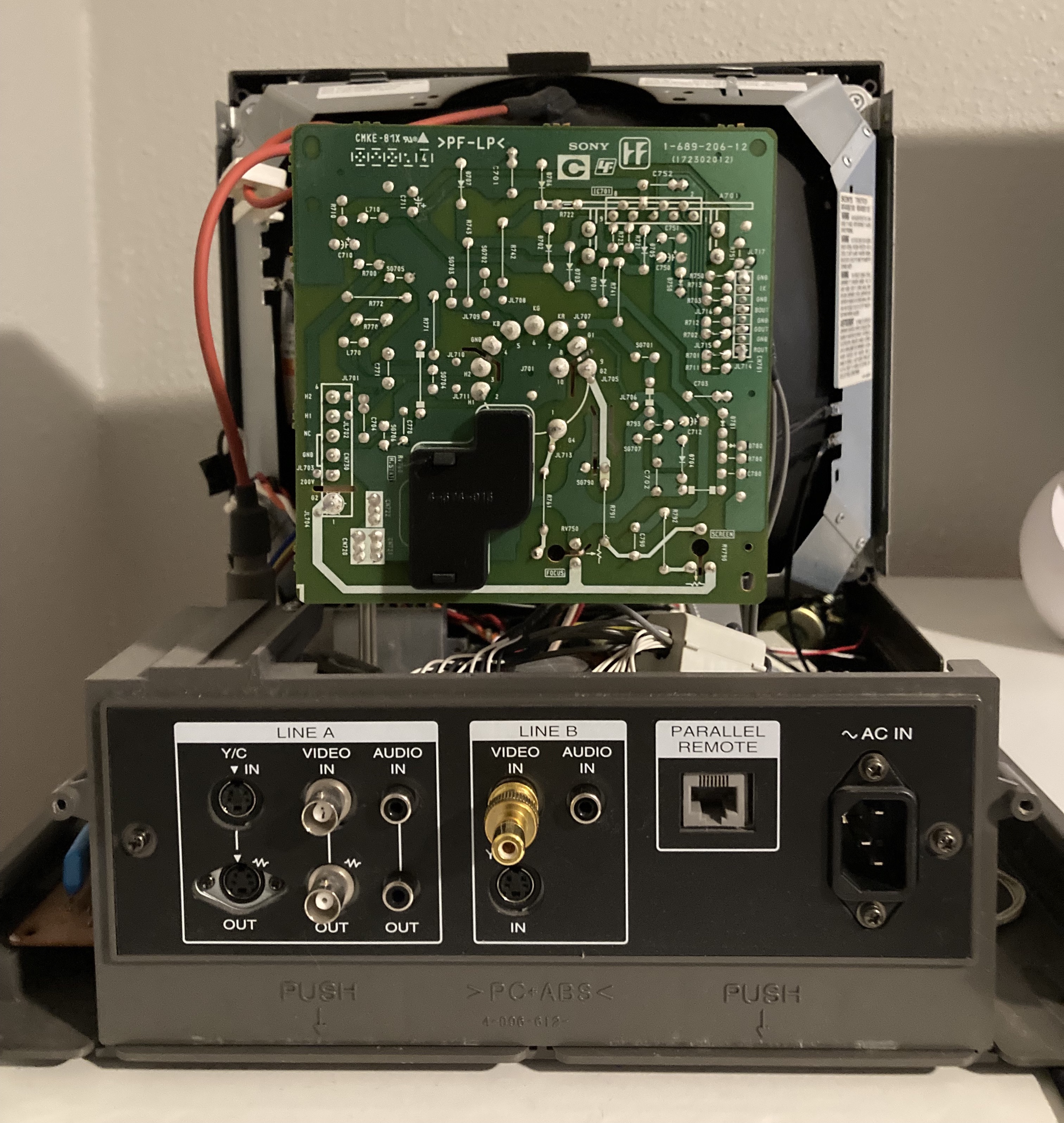
SCART port mounted 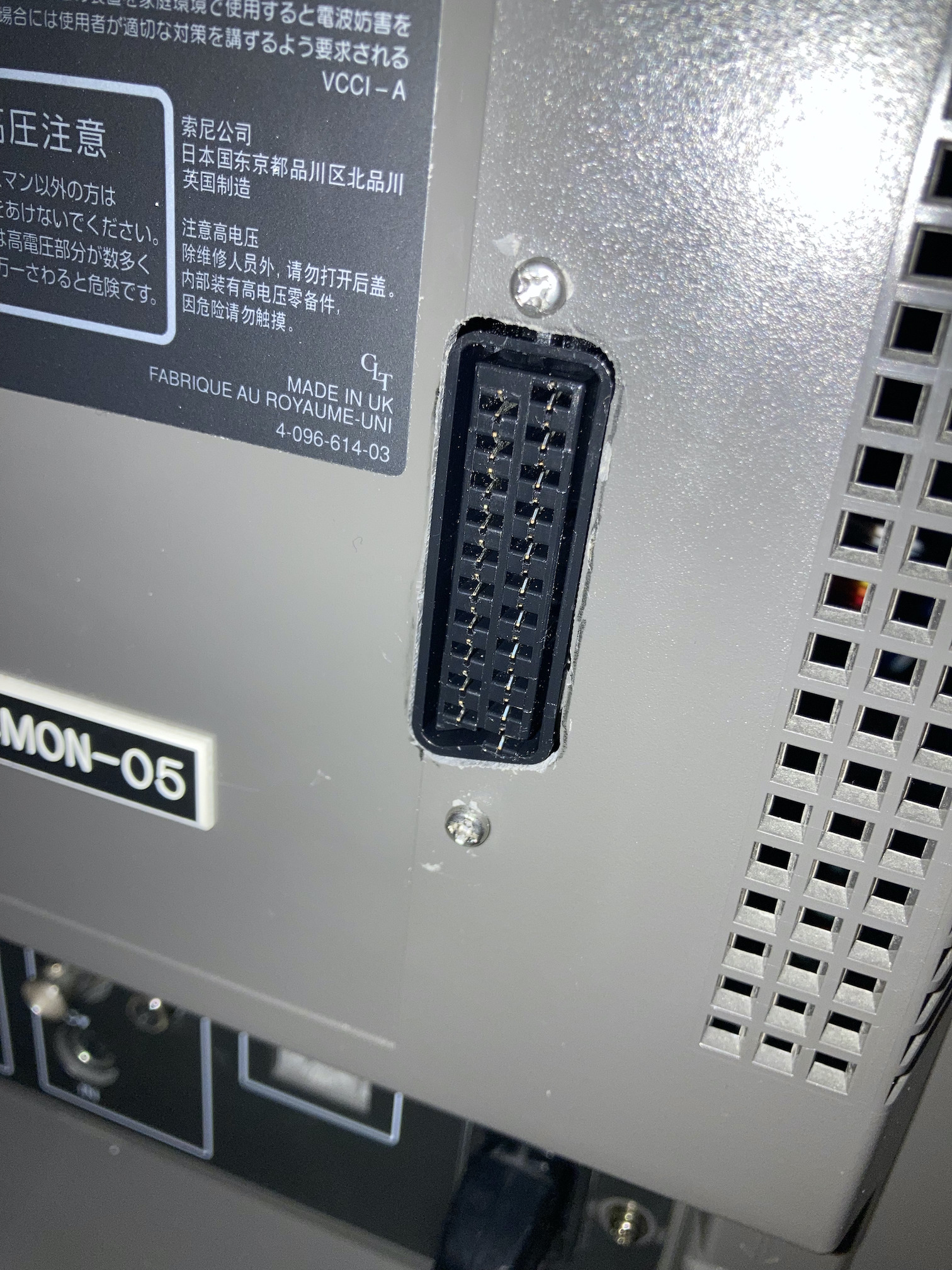
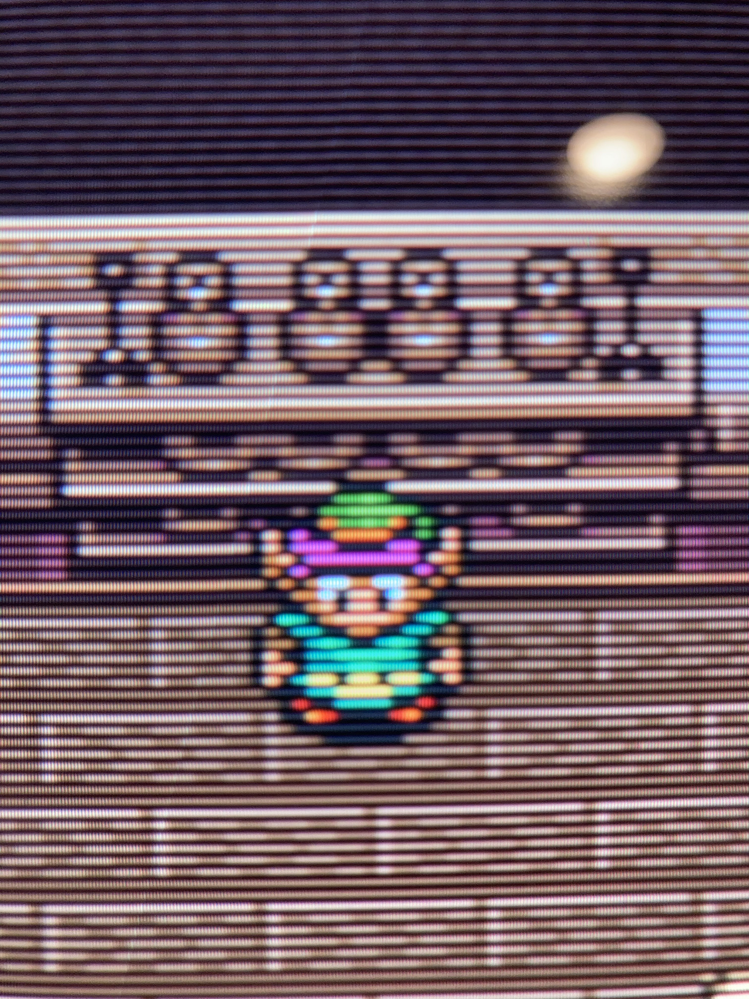
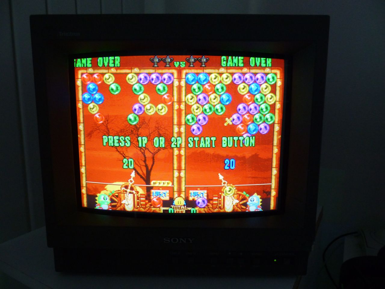
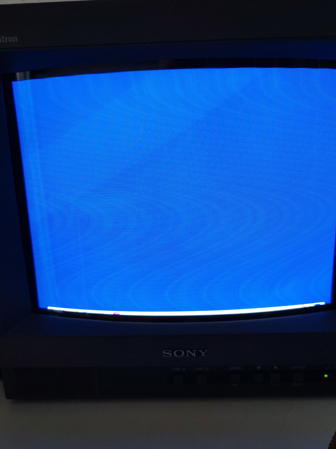
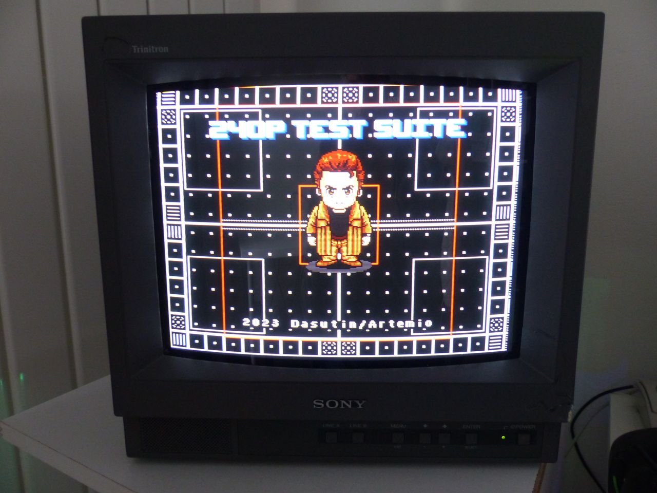
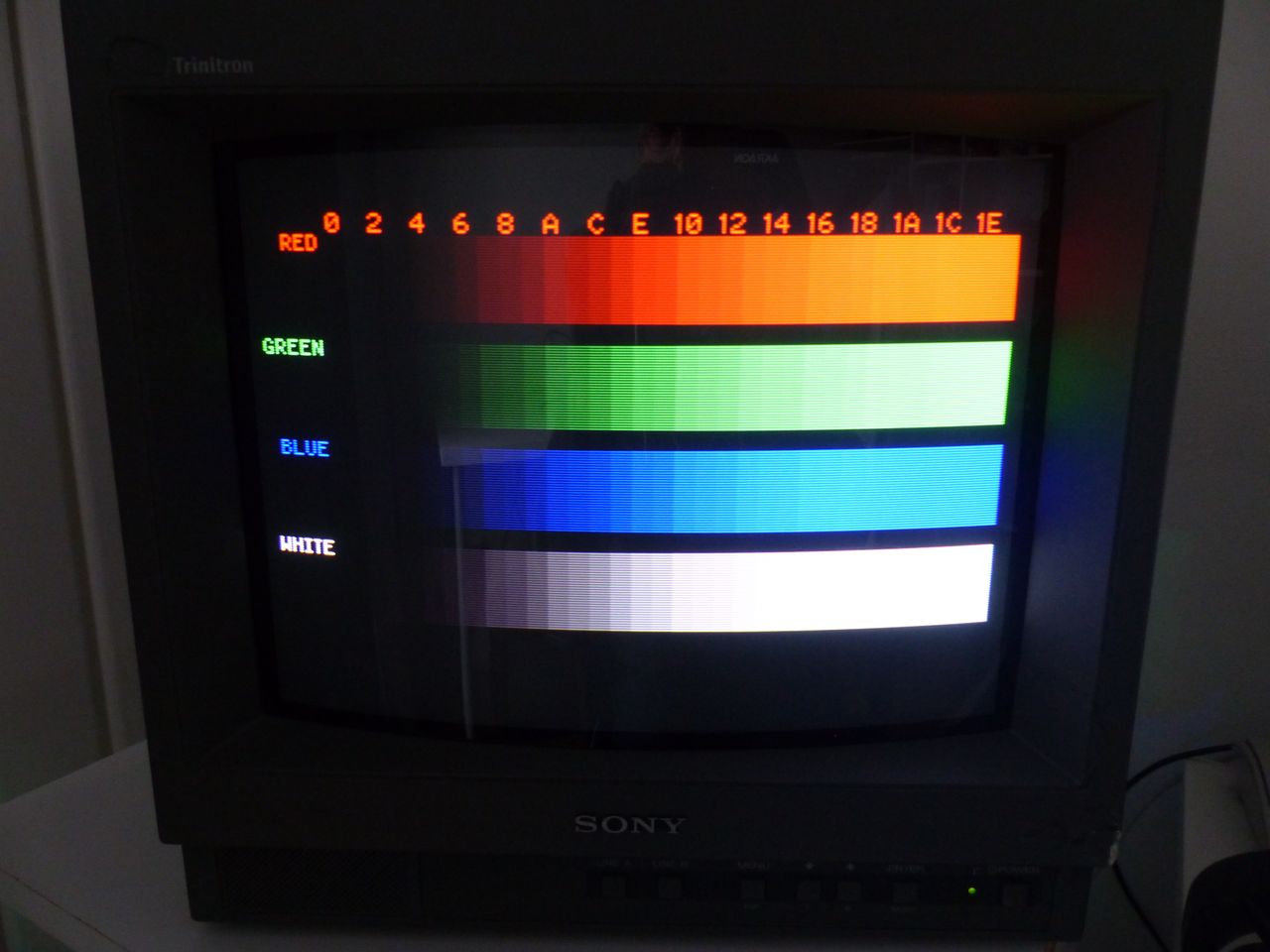
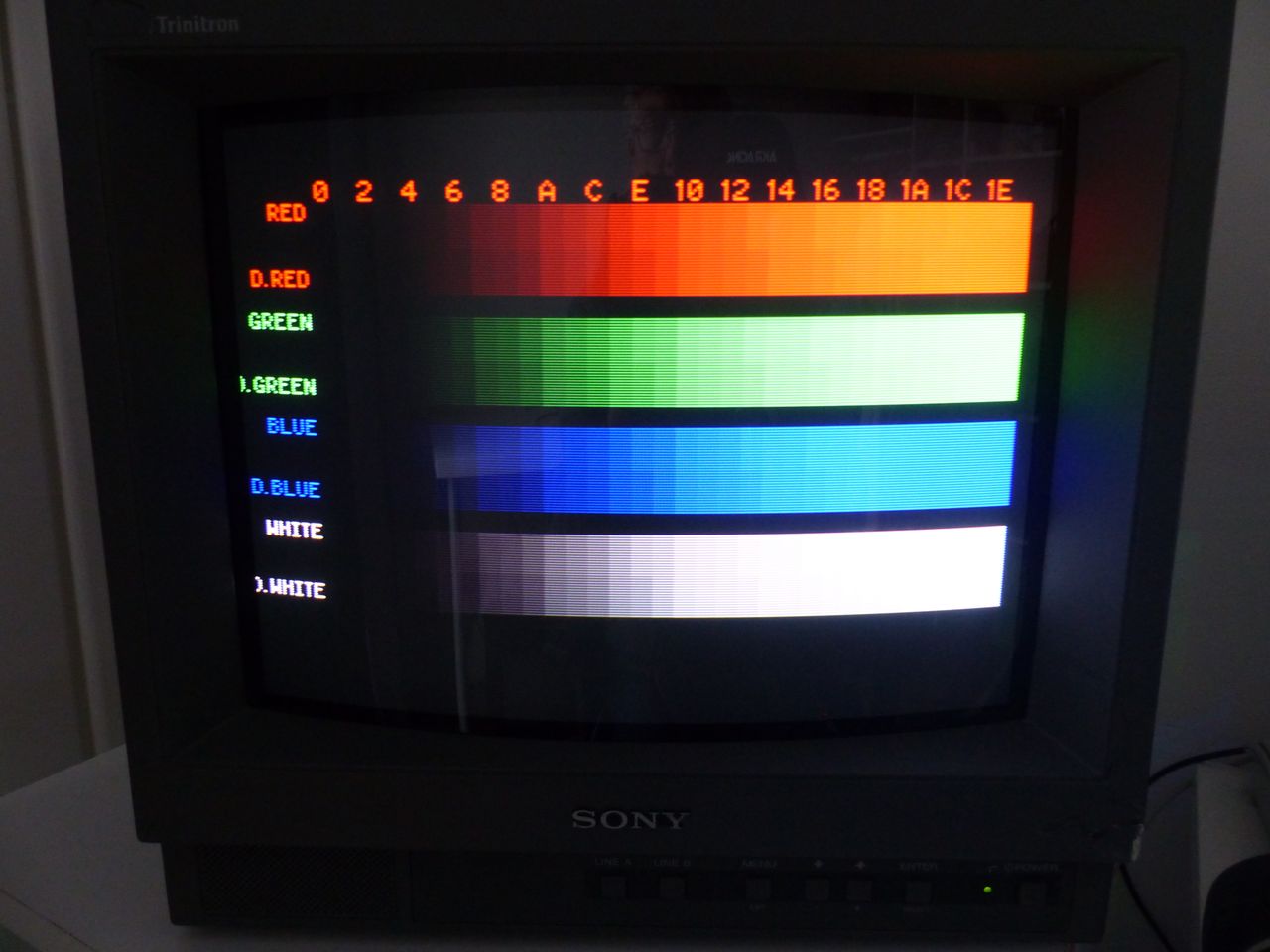
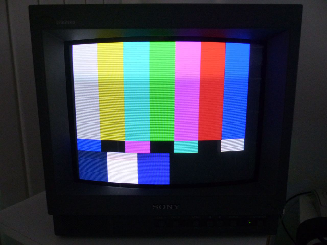
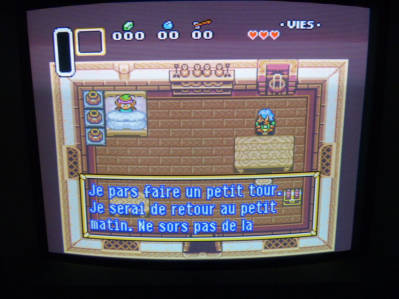
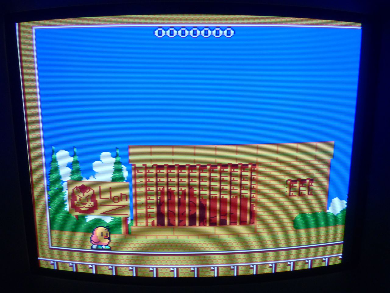
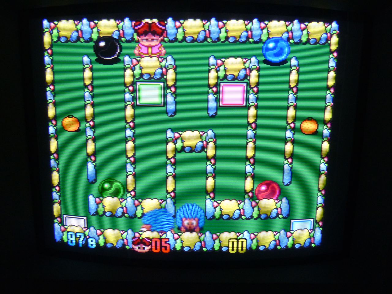
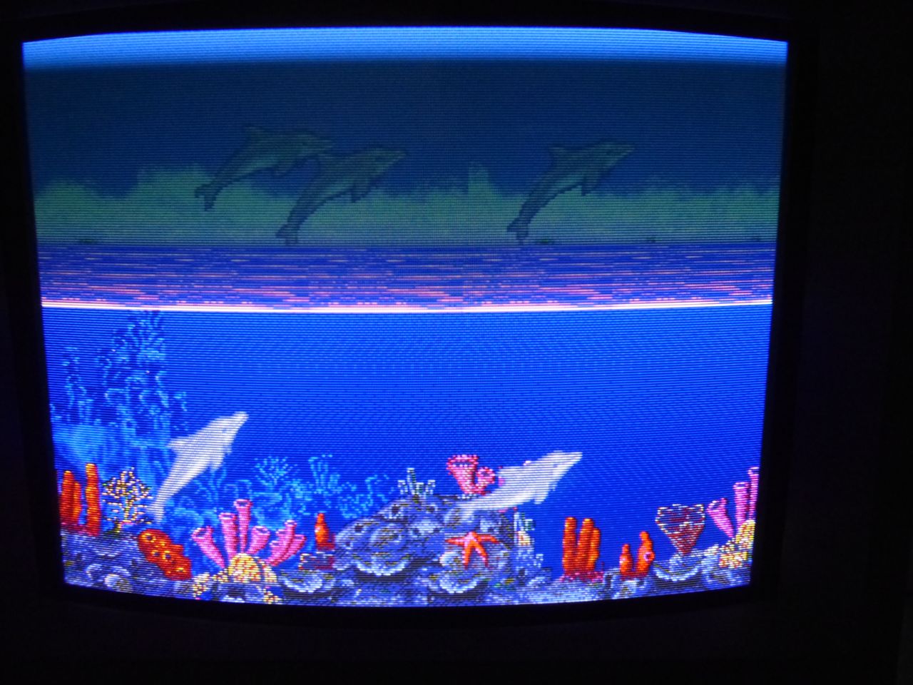
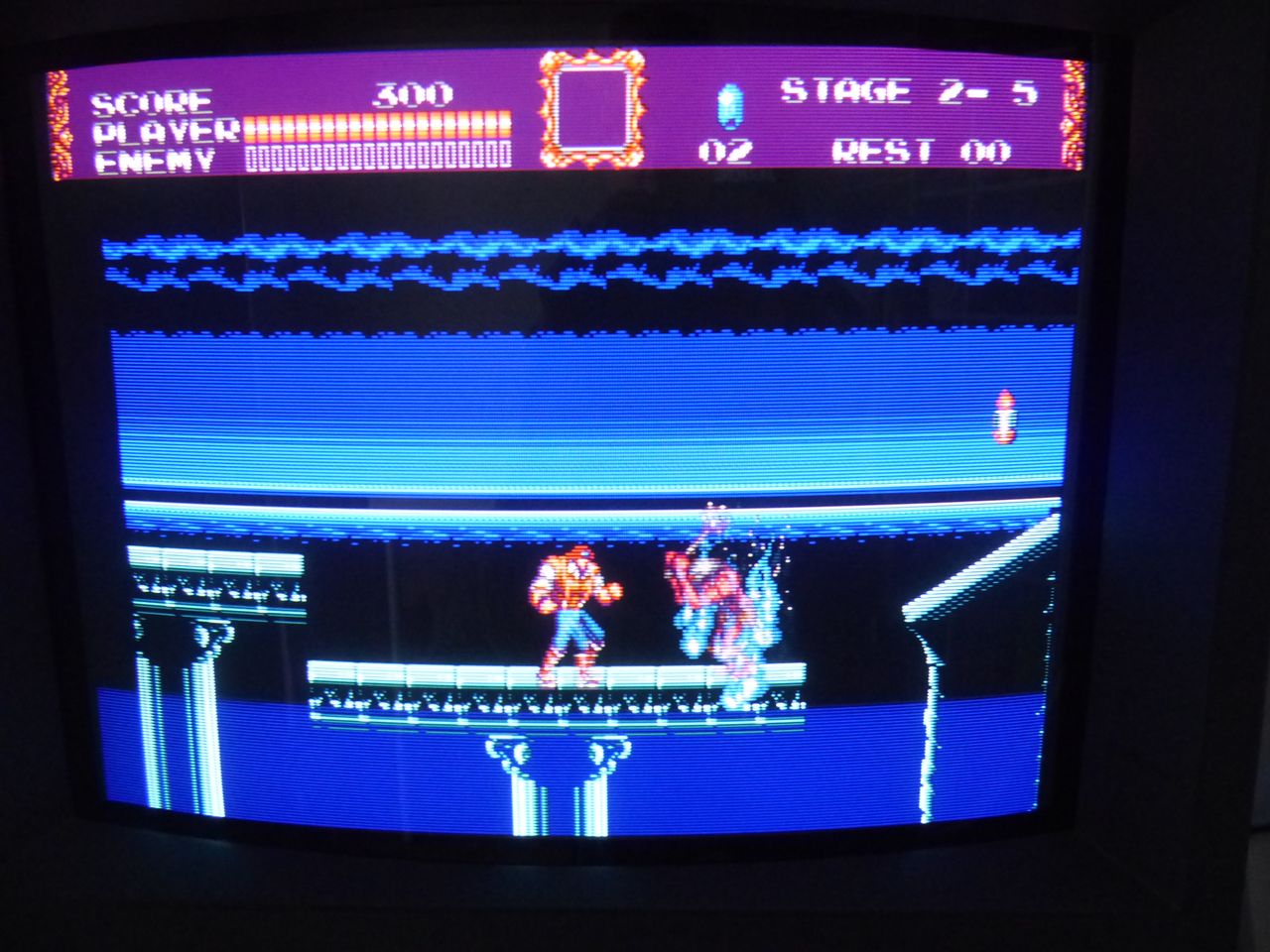
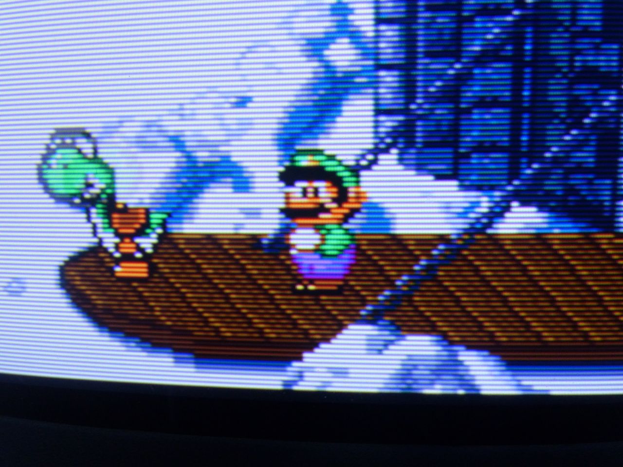
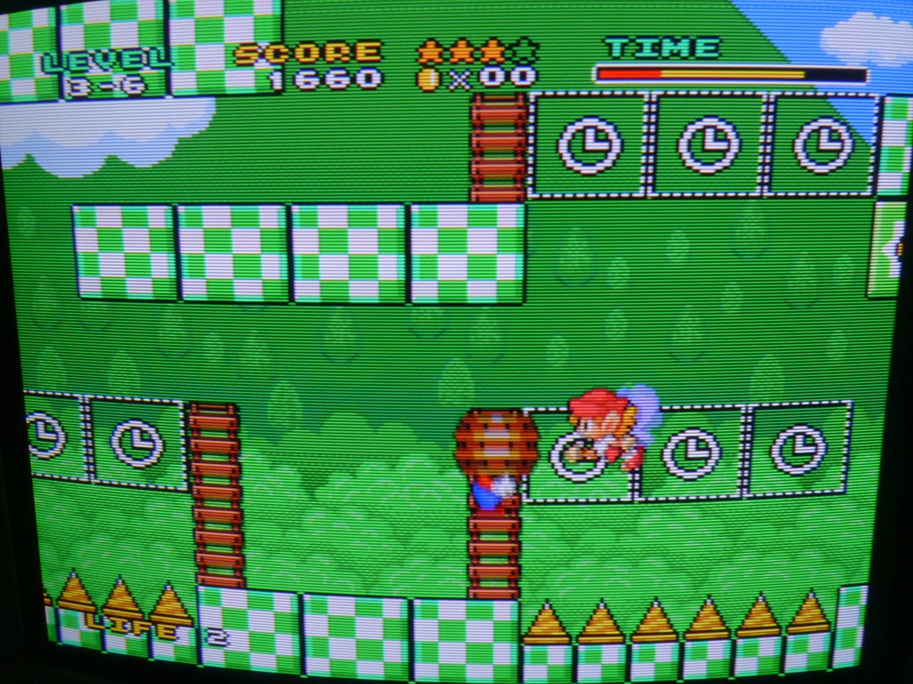
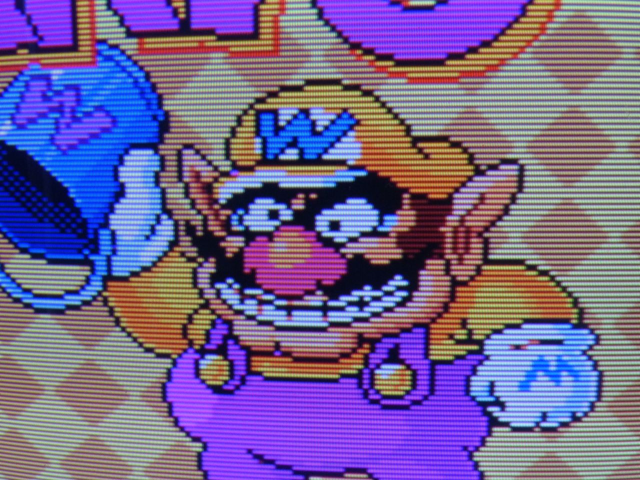
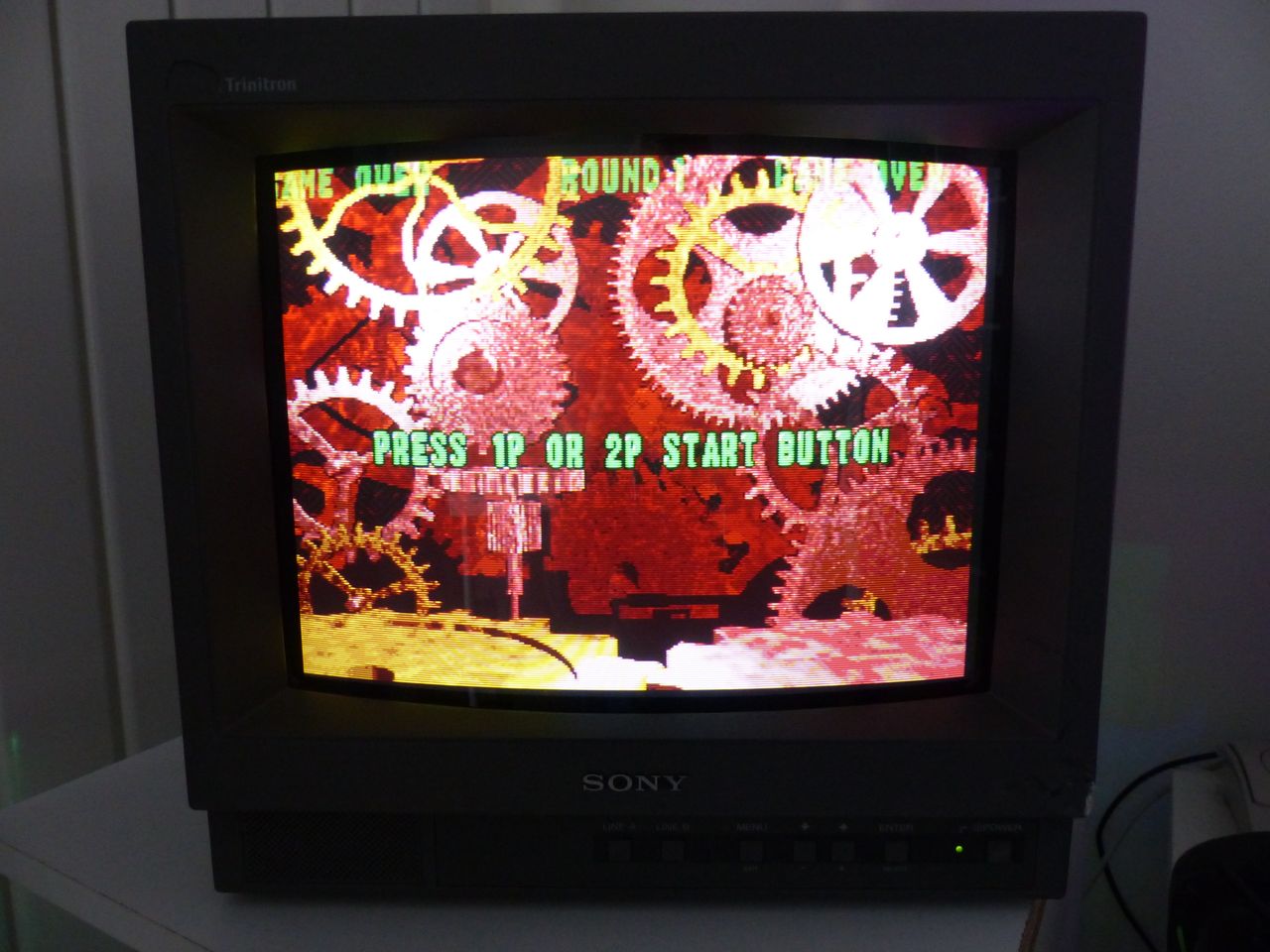
Game - RGB 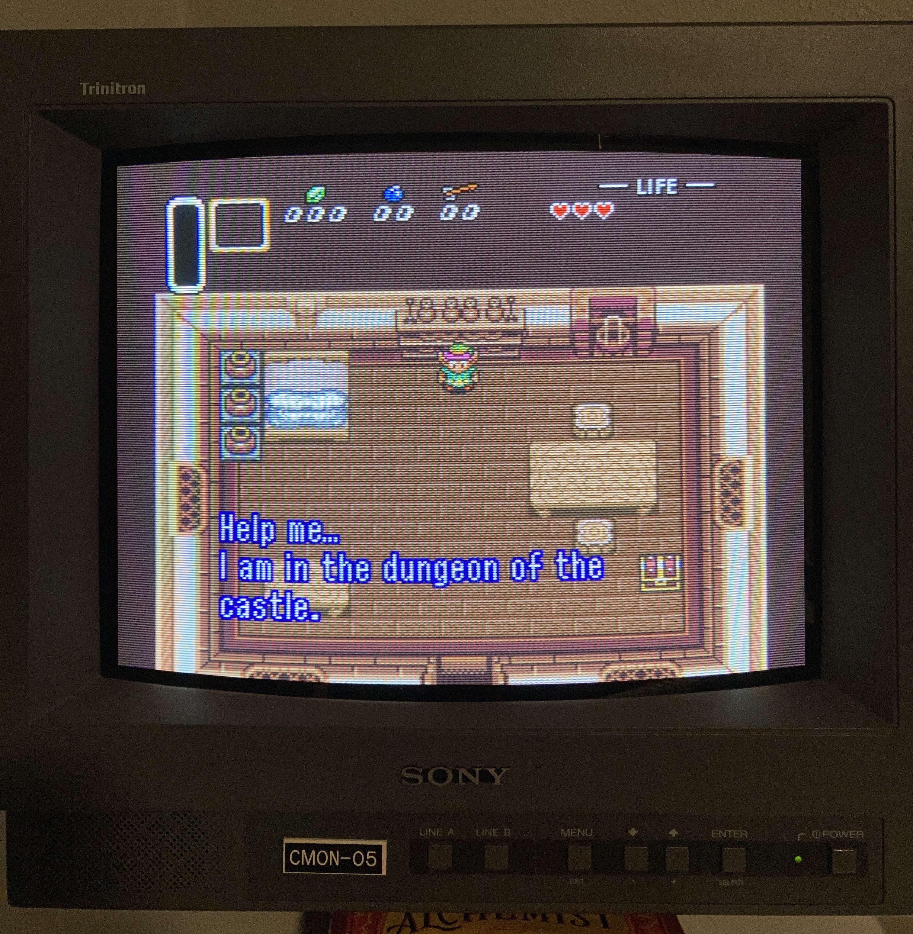
YPbPr Component notes:
TDA chips that support both YUV/RGB through the same pins require an address bit to be flipped to support one or the other. This by default is setup to accept RGB. Since I don't have the specific datasheet for this jungle IC, hard to tell exactly what bit needs to be flipped.
Pictures
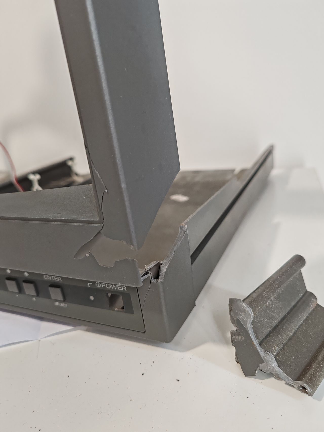
Photos by Bertrand POUPEAU
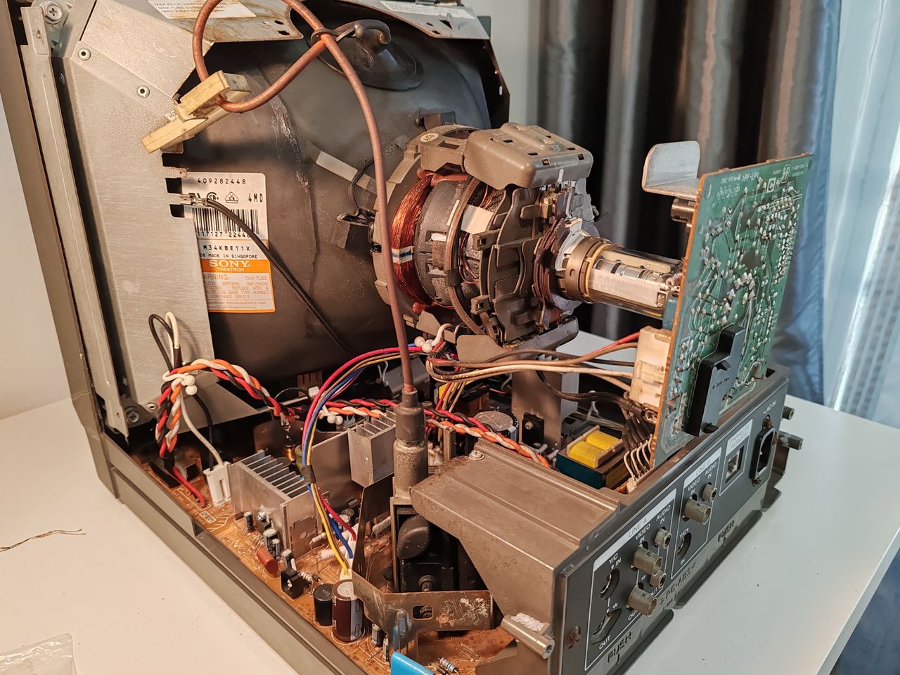
I've received this PVM, working, but in a very bad shape. The front bezel was broken during the travel from Japan to France. My goal was to repair the bezel, and to mount an RGB mux mod.
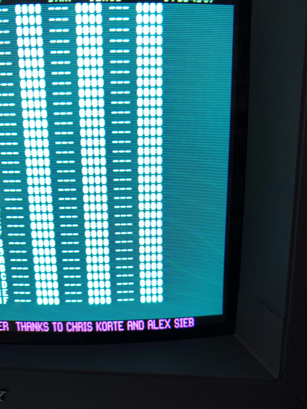
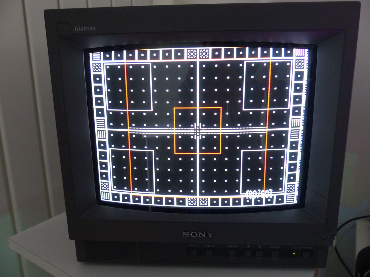
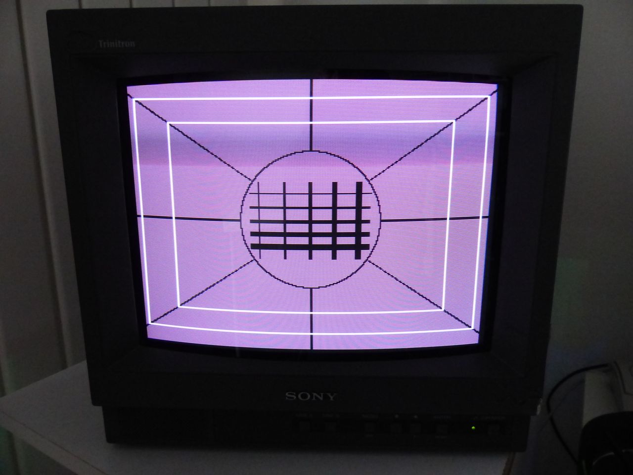
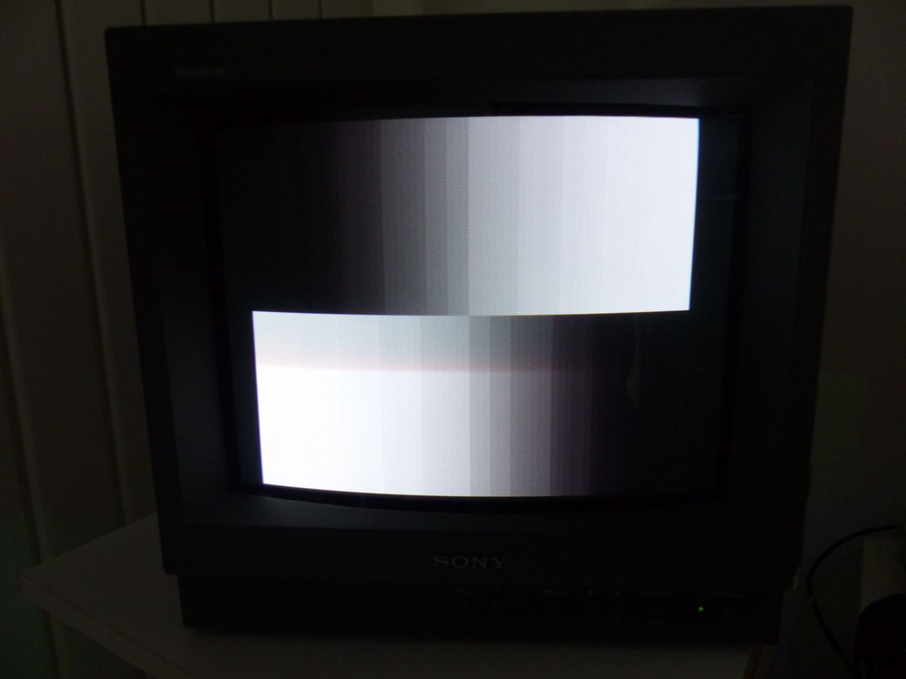
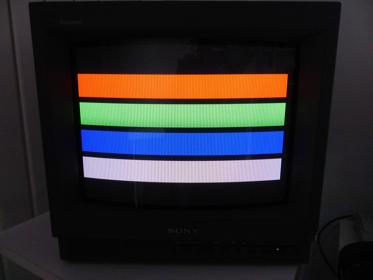
Reference Photos