JVC AV-27D201
JVC AV-27D201 CRT RGB mod
The JVC D-Series is a CRT that is popular among retro gamers. The curved CRT used in this model and its look are likely appealing to many because the tube was widely used in arcade cabinets in the 1990s. Some people prefer the earlier models that have fine pitch tubes. Even with some of the imperfections, the RGB image on it is one to behold.
View full CRT details and more mod examples →
Instructions should also work for JVC AV-32D201
AV-27Dx00 and AV-27Dx01 have full geometry adjustments compared to the later models. AV-27Dx00 and AV-27Dx01 have the same tube A68AEG25X01.
Contributors
Thank you to everyone who contributed to this guide:
- Eli Krause — contributor, CRT specs from CRT Database.
- Sunthar — author, RGB mod and pictures
CRT safety
Caution
You can die doing this! So read carefully! CRT TV is not a toy. Do not open a CRT TV. If you don't have any prior knowledge about handling high voltage devices, this guide is not for you. CRT TV contains high enough voltage (20,000+ V) and current to be deadly, even when it is turned off.
Plan of attack
Manuals and Datasheets
Specs
- Year: 2000
- Format: NTSC
- Chassis: GR2
- Tube: A68AEG25X
- Jungle Chip: JVC JCC1007A
- OSD Chip: Matsushita MN1876478JD
- Screen Size: 27"
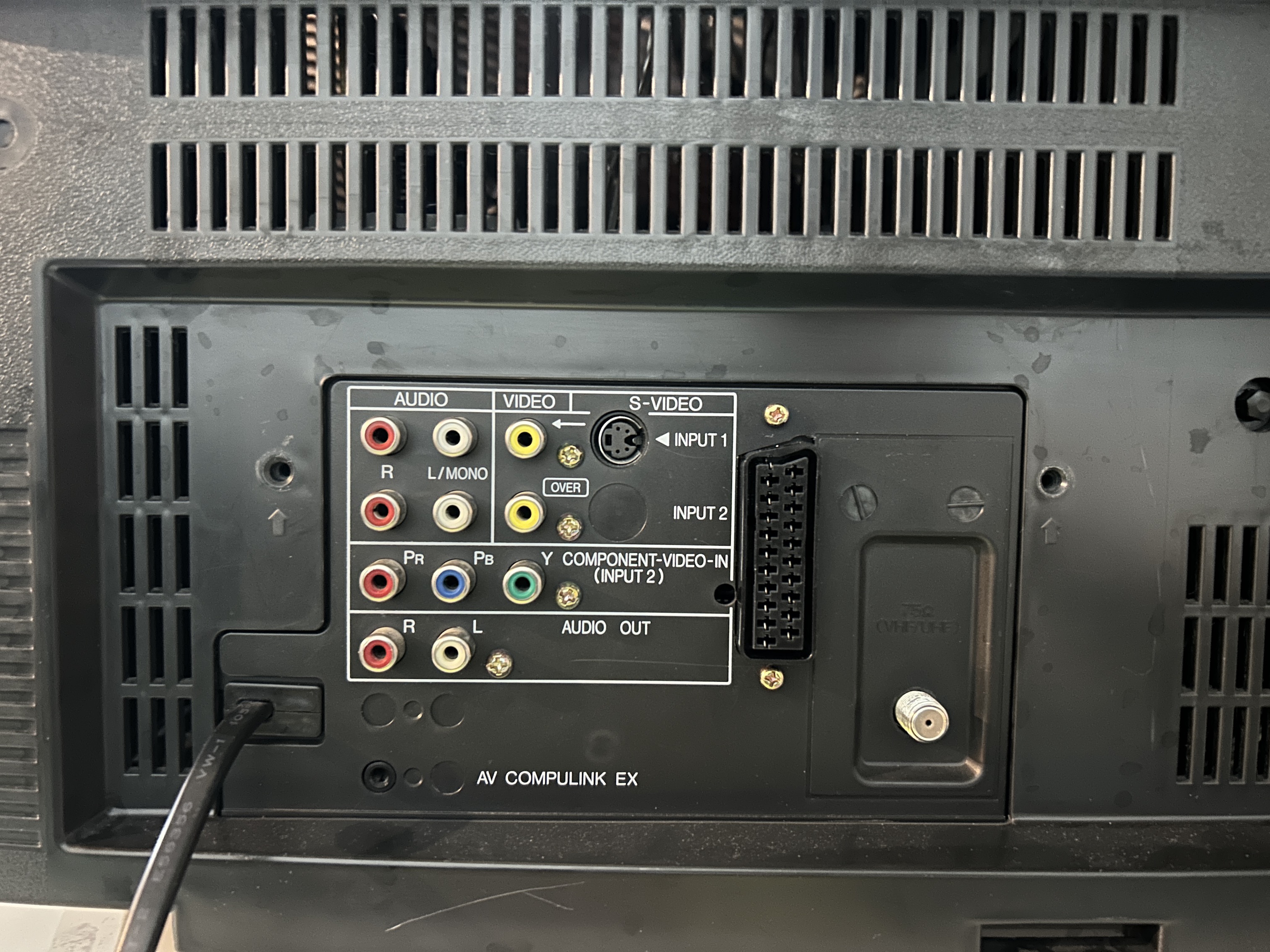
- Inputs: Composite, S-Video, RF, Component YPbPr
RGB mux diagram
Performing the mod
Now that you roughly know what needs to be done, prepare for the mod. Place the board on a comfortable place. Make sure you are not putting pressure on the flyback or other components.
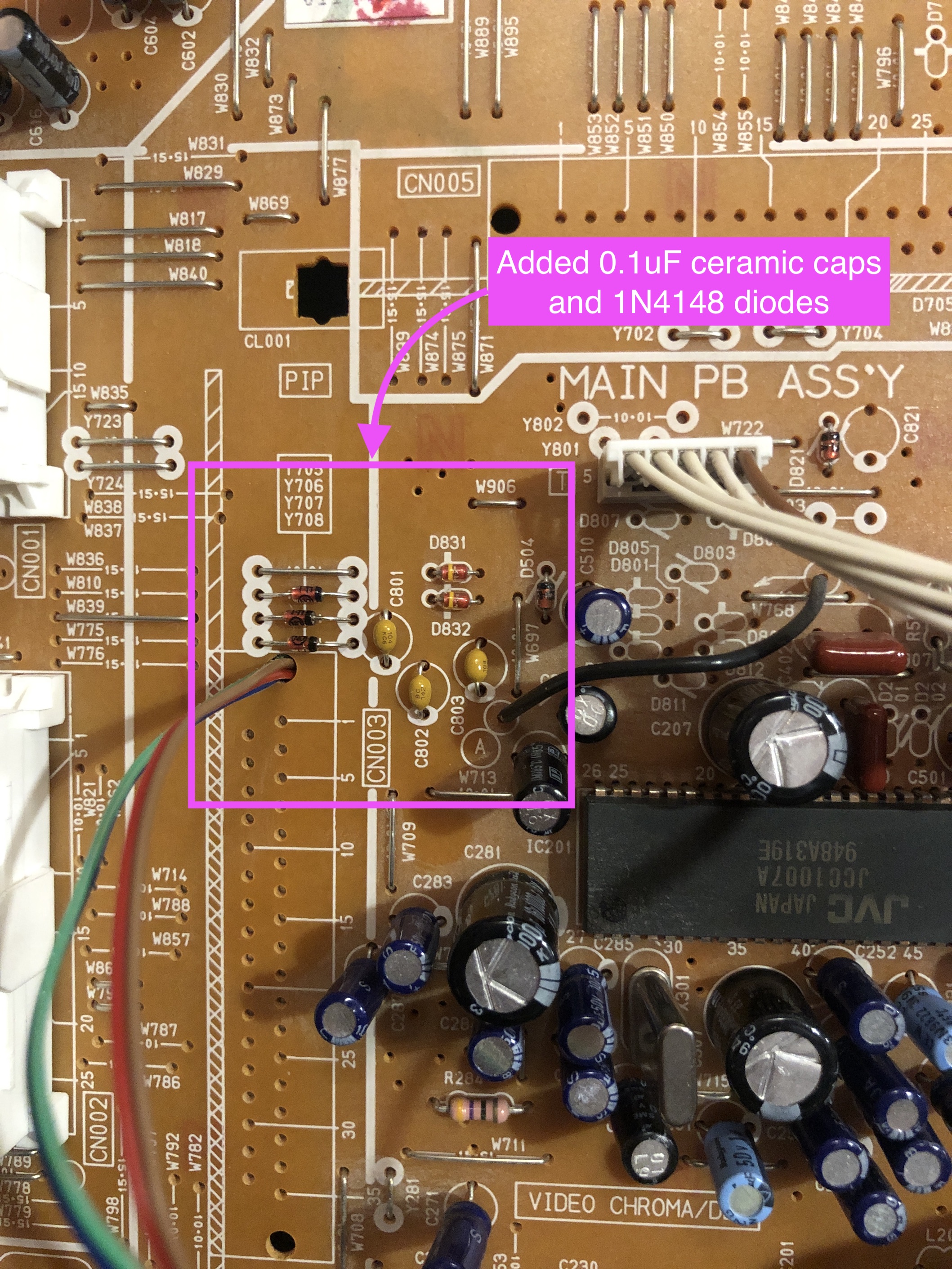
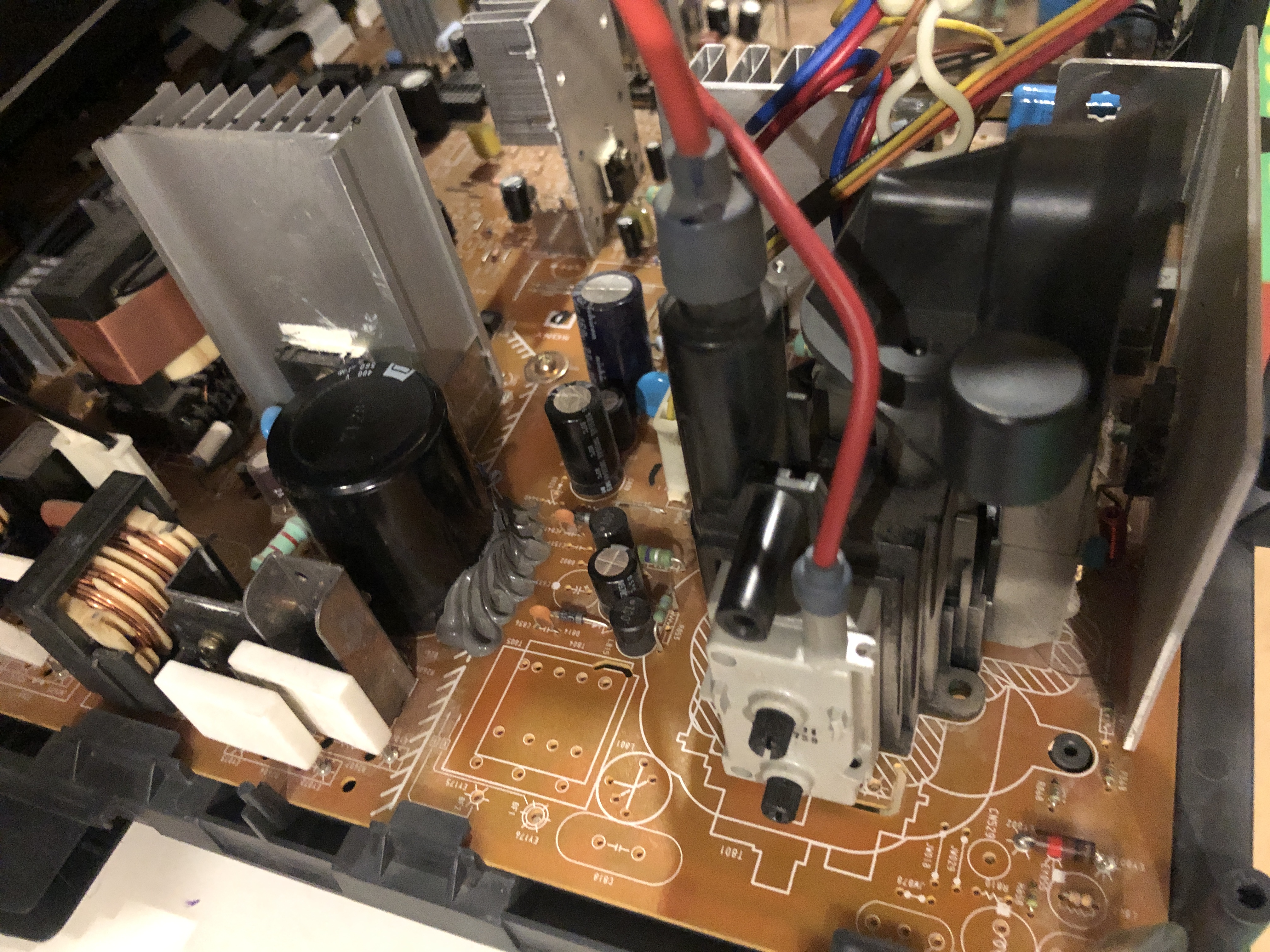
STEP 1: Add caps and diodes
- Remove stock electrolytics caps and replace C801, C802, C803 capacitors on chassis with 0.1uF ceramic capacitors.
- Replace jumpers Y706, Y707, Y708 with diodes. Pay attention to the direction of the diodes.
STEP 2: Remove and replace the following components
There are two areas to focus for STEP 2 and 3 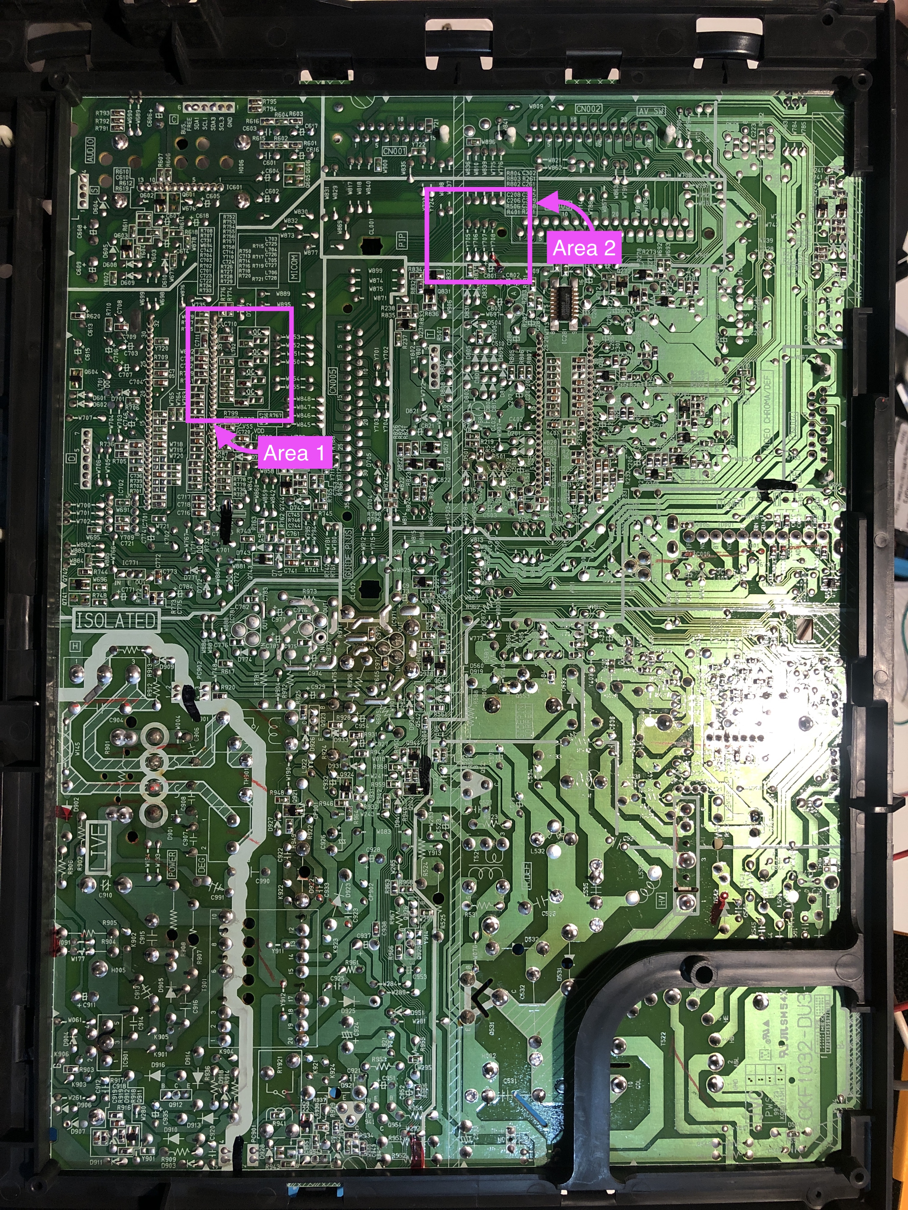
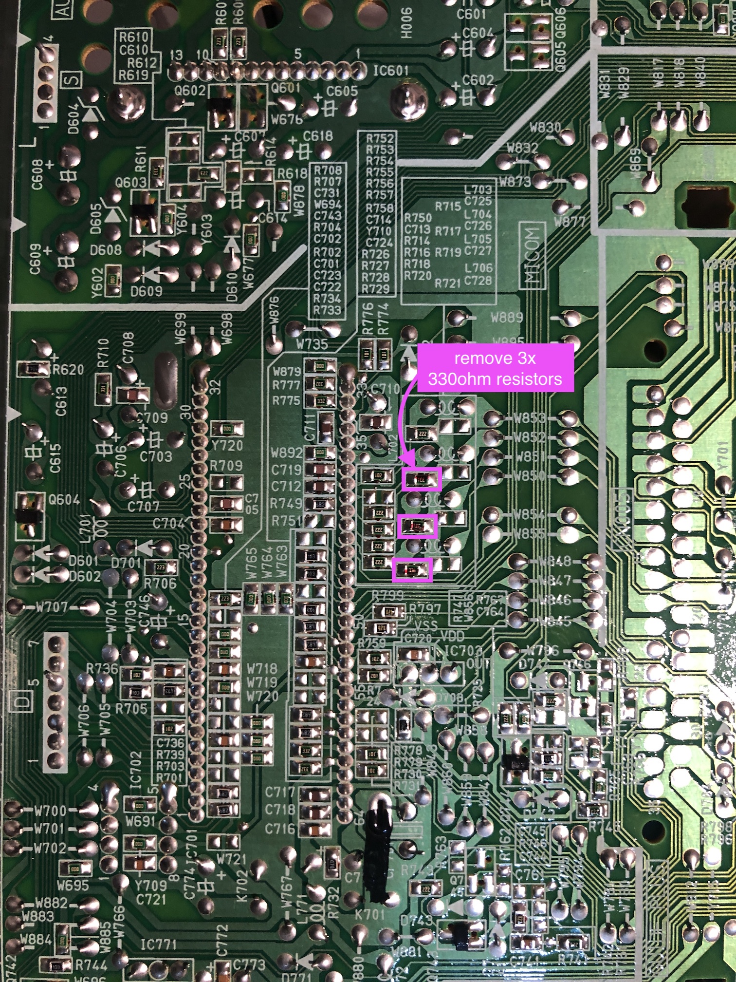
First focus on Area 1 and remove the following three SMD resistors.
- R717 (330 ohms)
- R719 (330 ohms)
- R721 (330 ohms)
STEP 3: Connect RGB, Blanking wires
Next, focus on Area 2 and attach the blanking wires. There is a conveninet hole nearby to route the wires. Make sure you are soldering the wires to the correct leg.
![]()
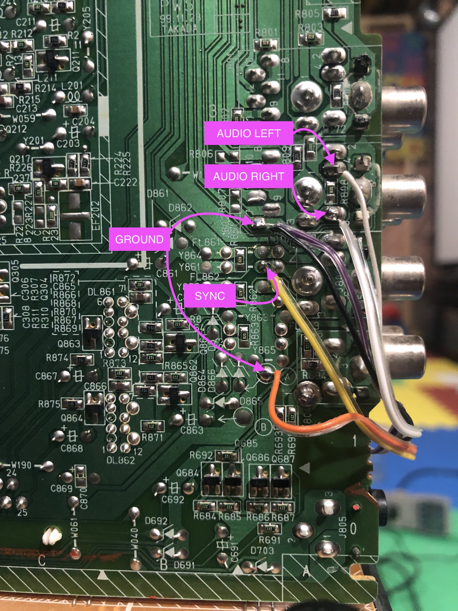
STEP 4: Sync and audio wires
Sync goes to the green component jack (Video Input 2). Left and right audio also goes with the Input 2.
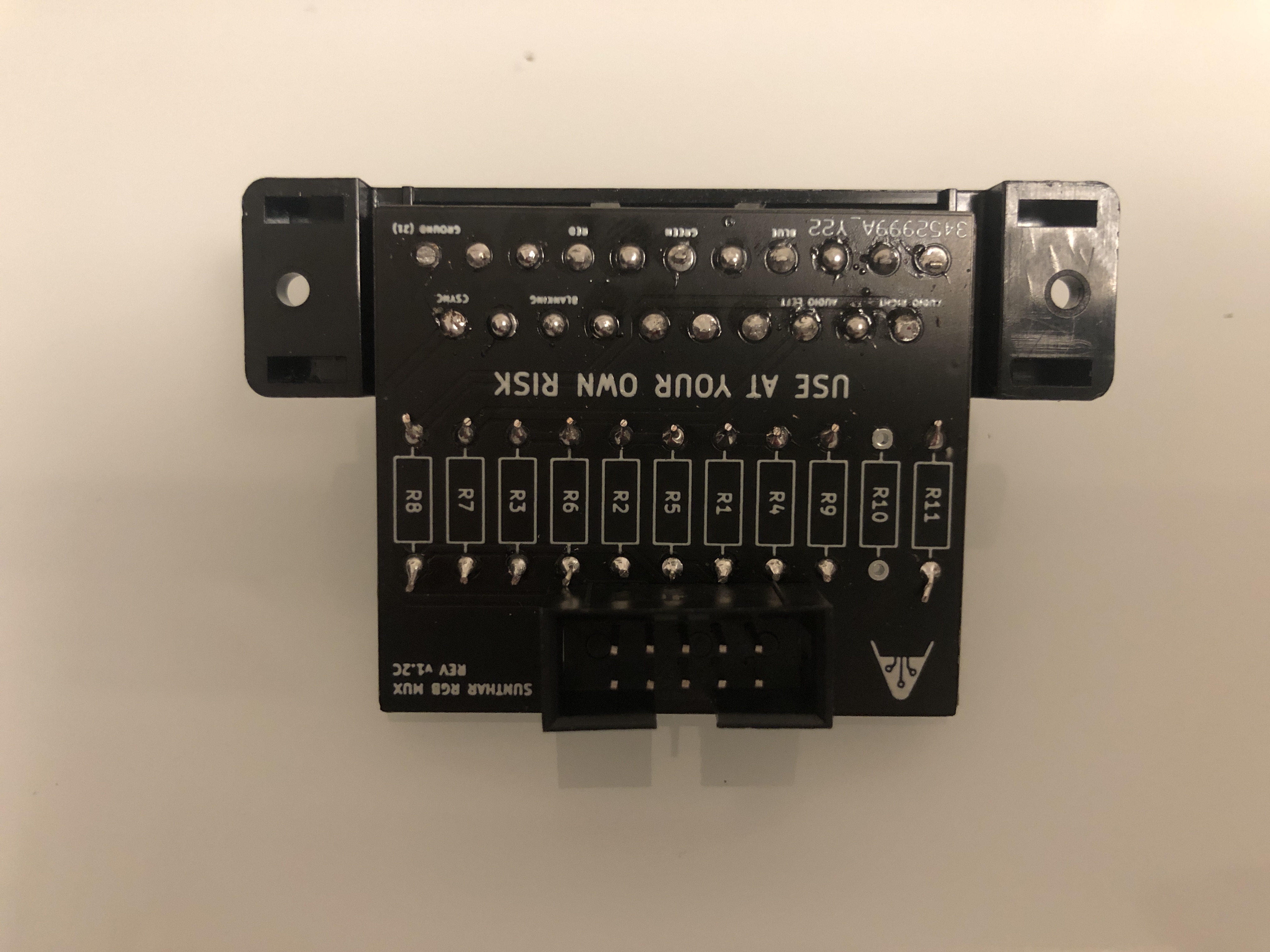
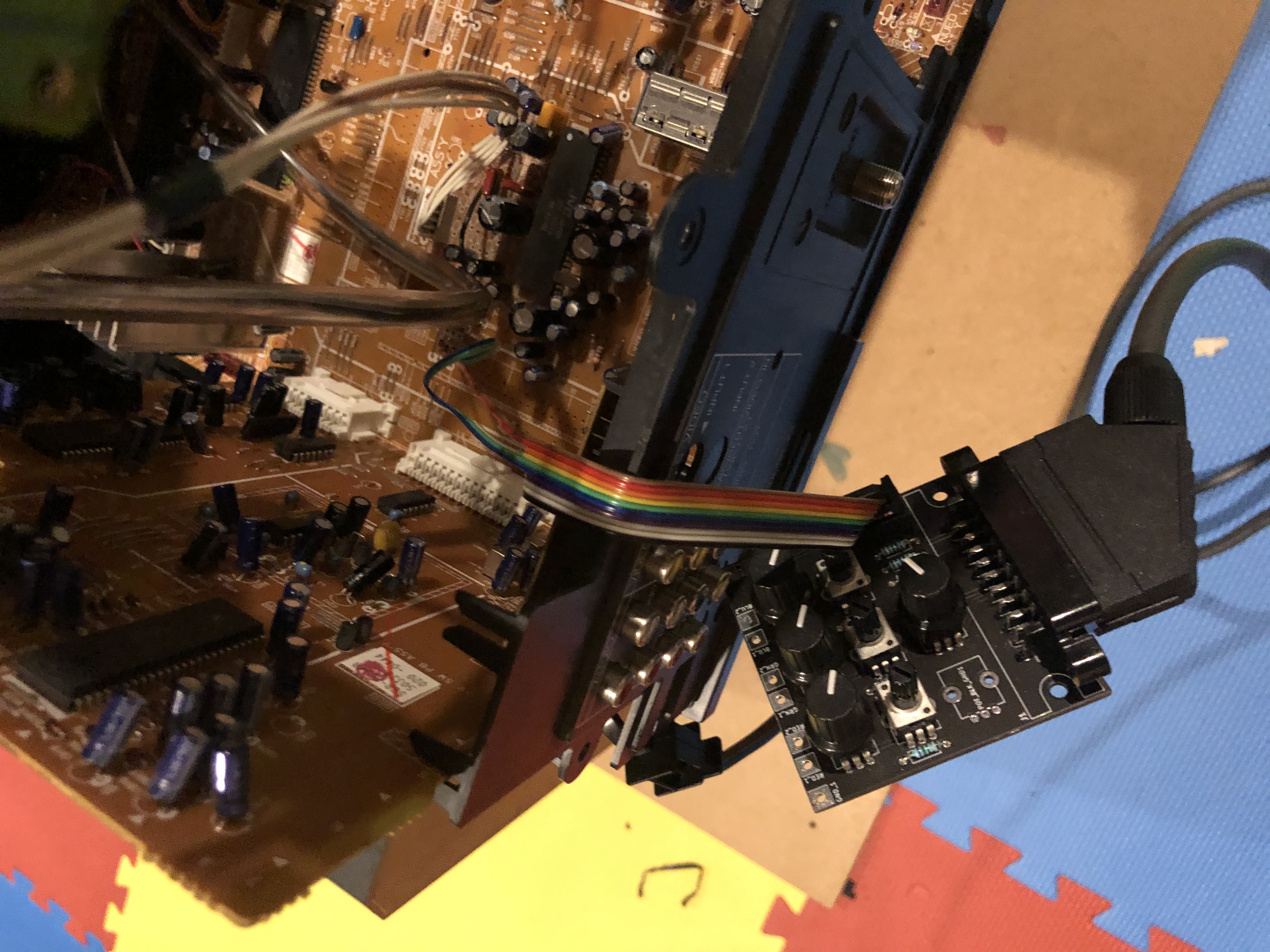
STEP 5: Build your mux board
This mod uses the RGB mux board. This is optional, but will make your mod easier and stable. You can also create the circuit presented in the schematics above without the board. Please also checkout the mux calculator to play with your own values.
| Component | Value |
|---|---|
| RGB/OSD inline resistor (chassis) | 2.2kΩ |
| Removed RGB/OSD resistor (chassis) | 330Ω |
| RGB inline diode method (chassis) | Yes |
| 0.1μF caps replaced (chassis) | Yes |
| RGB termination (R1, R2, R3) | 75Ω |
| RGB inline (R4, R5, R6) | 390Ω |
| Audio LR (R7, R8) | 1kΩ |
| Diode (R9) | 1N4148 |
| Blanking Ground Resistor (R10) | open |
| Blanking Resistor (R11) | 1kΩ |
I used a different version of the RGB mini mux board (Rev C) here to perfectly fit this on the back of the D-Series.
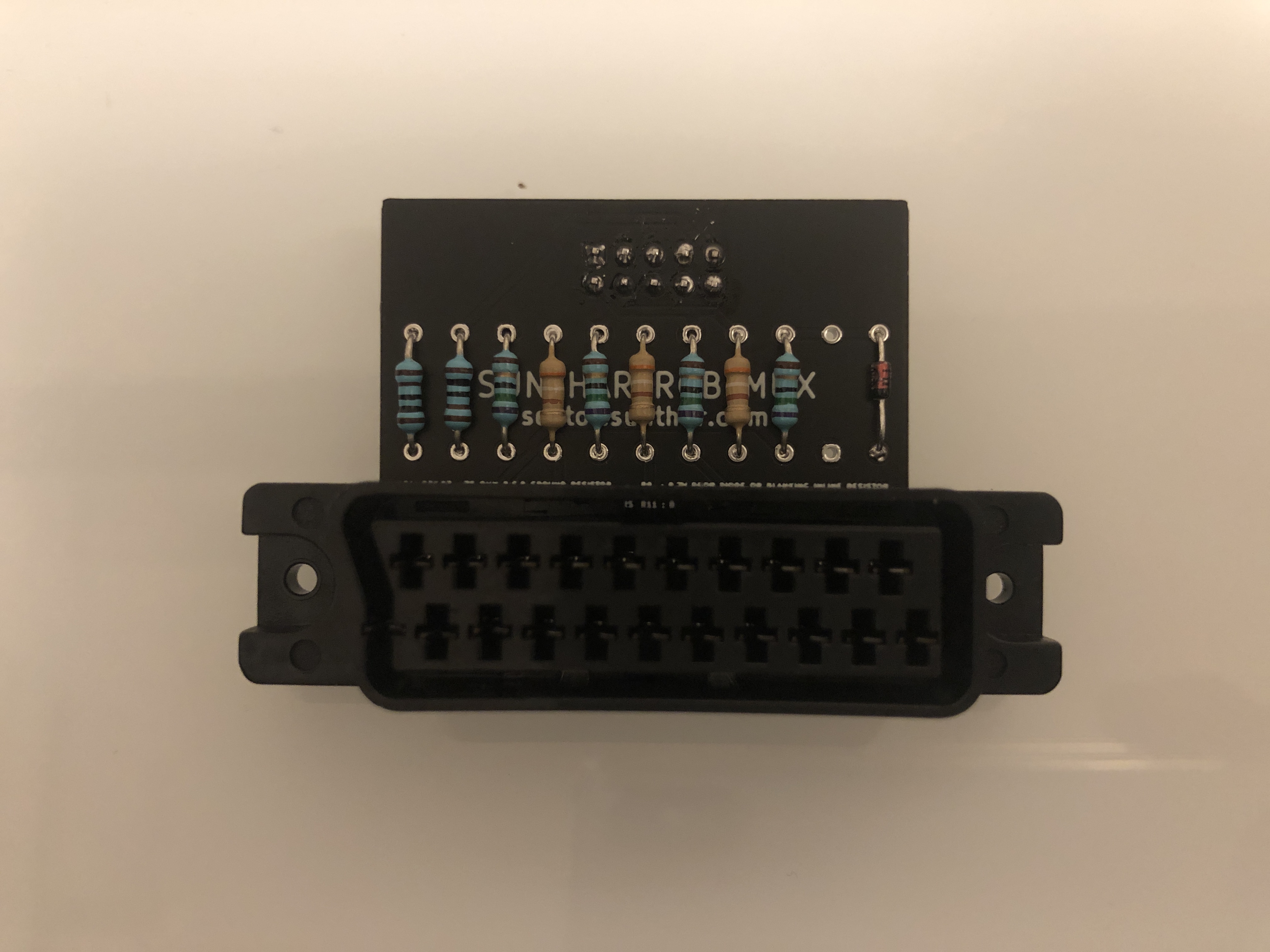
Look at the tight fit in the below pictures.
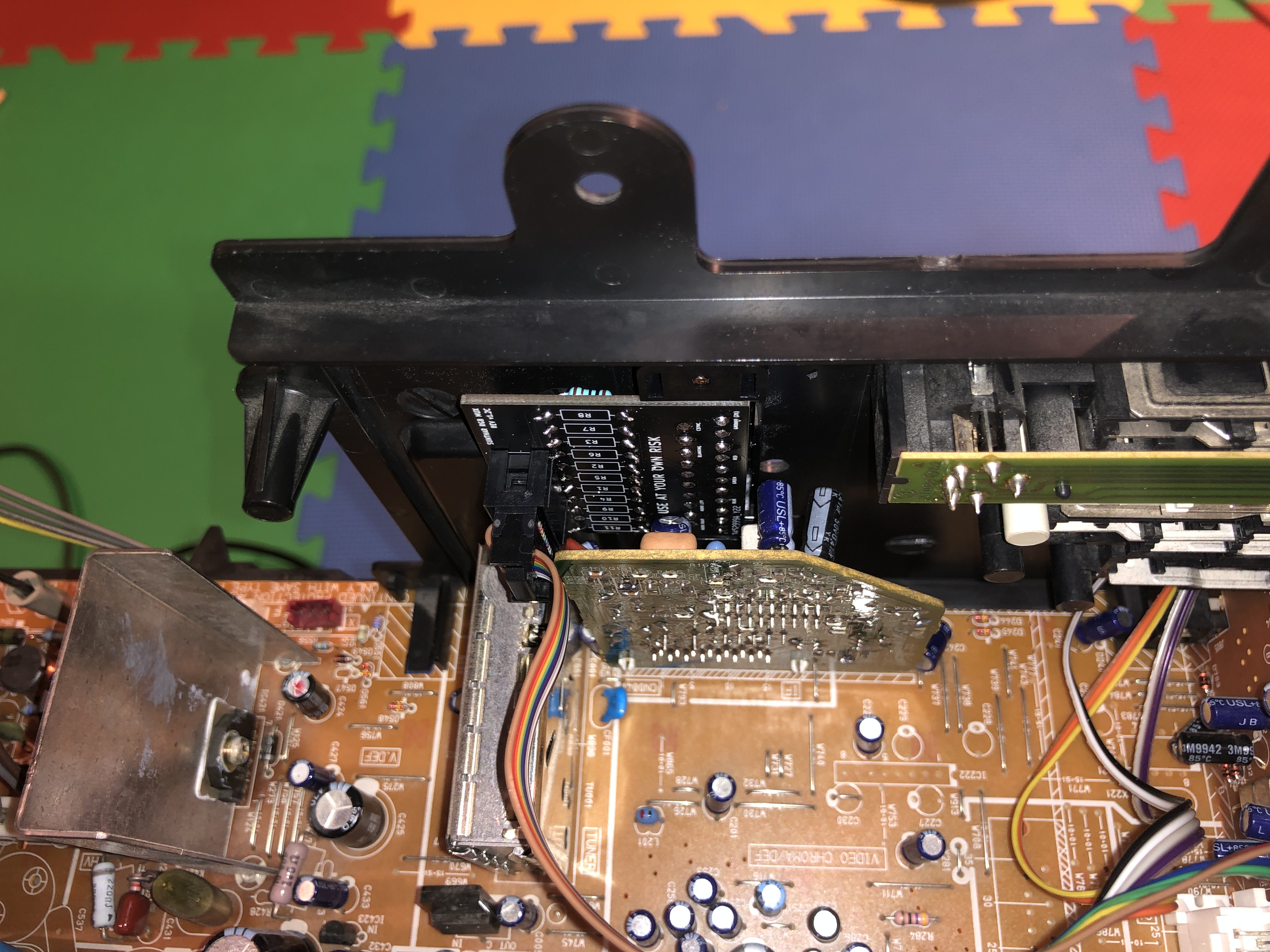
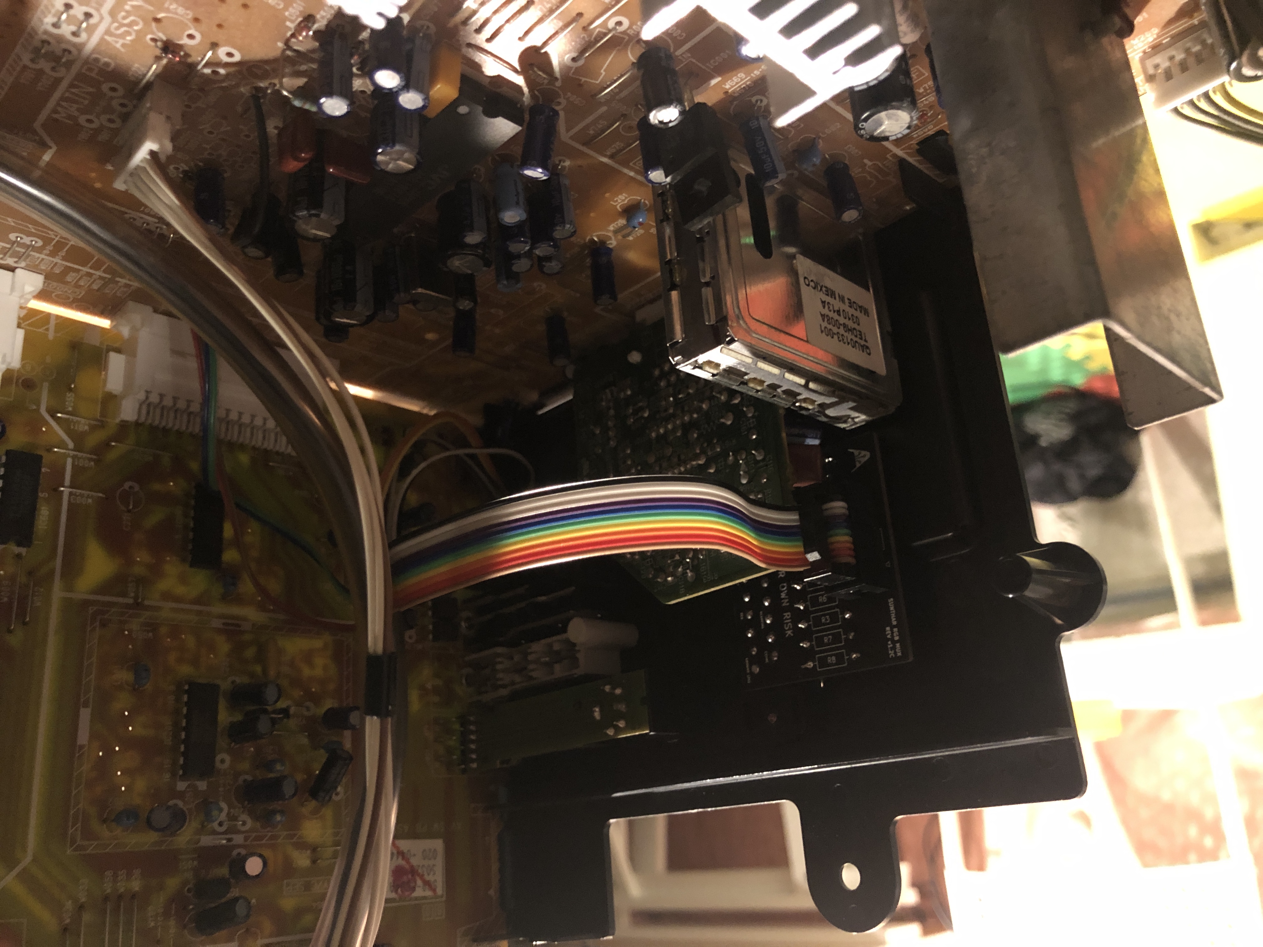
One must carefully plan where the mux board should go.
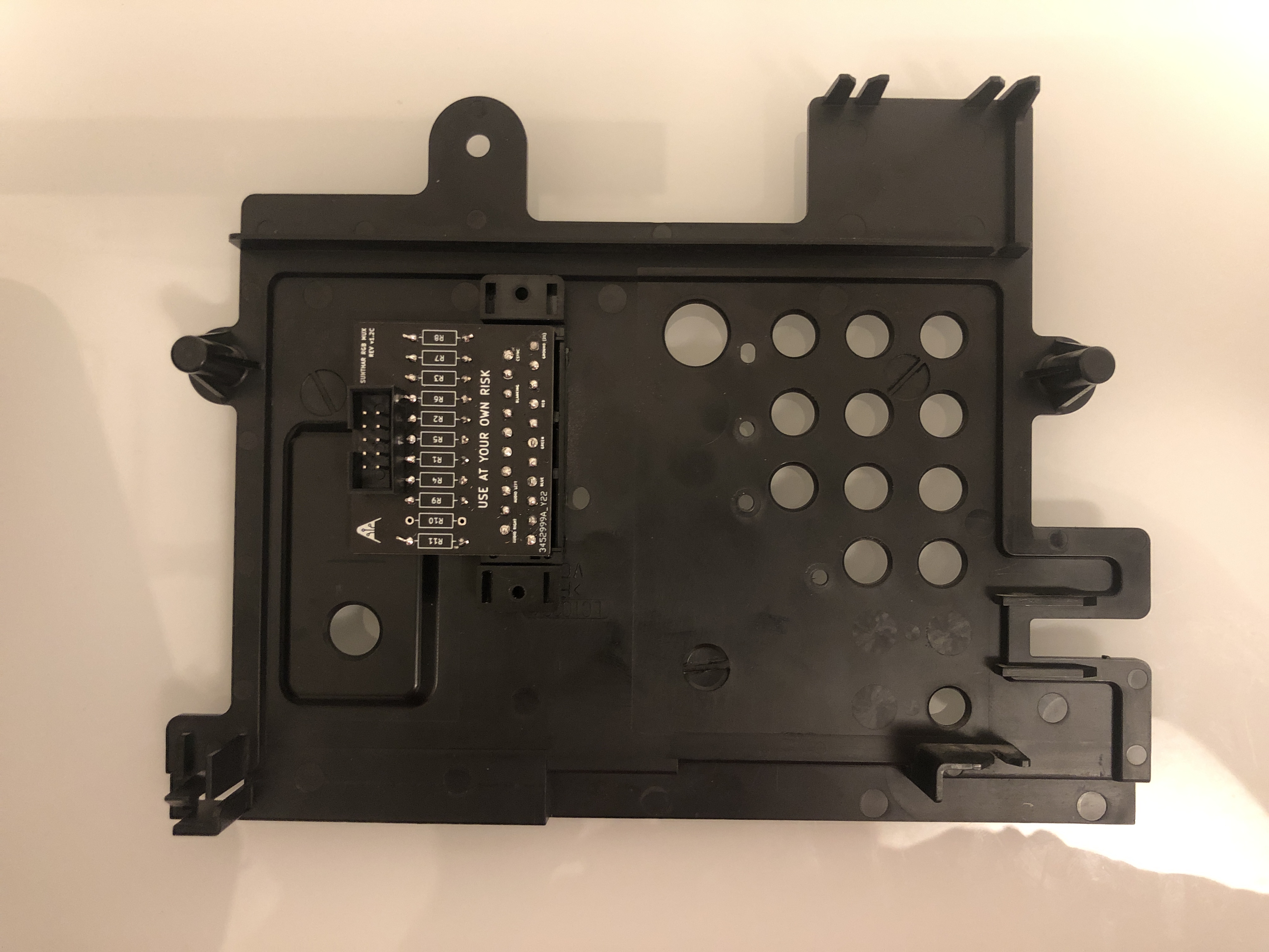
End result is very satisfying. This is where the SCART port belongs on a 27", D201.
STEP 6: Attach the female SCART connector to TV
Creating a SCART cutout and mounting it is an art. I have a dedicated section for it. How to create and mount a SCART female plug?

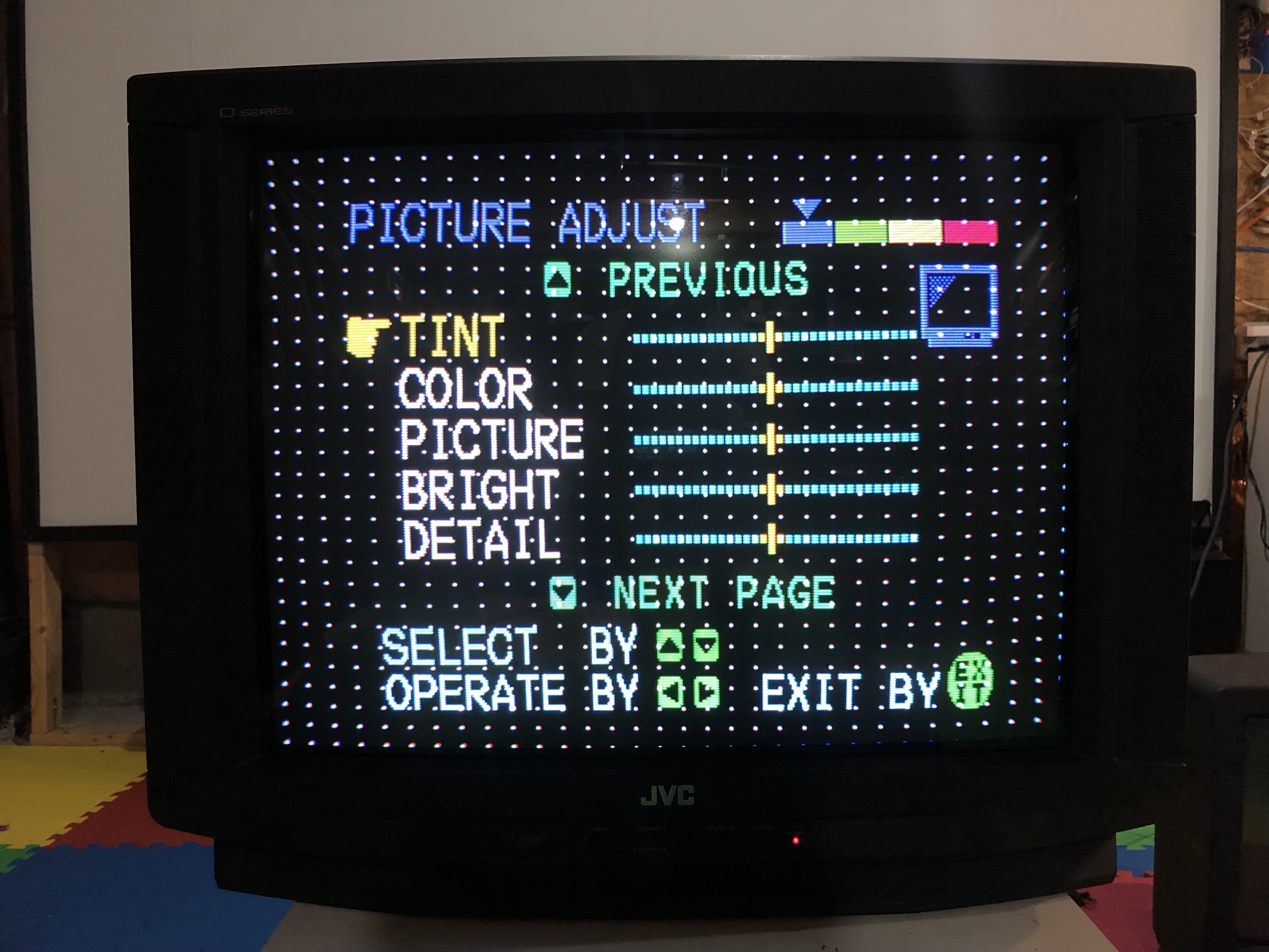
Service Menu
- Press the
SLEEP TIMERkey and set theSLEEP TIMERfor0 MIN - While the
SLEEP TIMERis displaying on the CRT, do the below - Immediately press the
DISPLAYkey and theVIDEO STATUSkey of the remote control unit at the same time. - Then enter the
SERVICE MENUscreen shown in figure.
Mux overlay
RGB Overlay 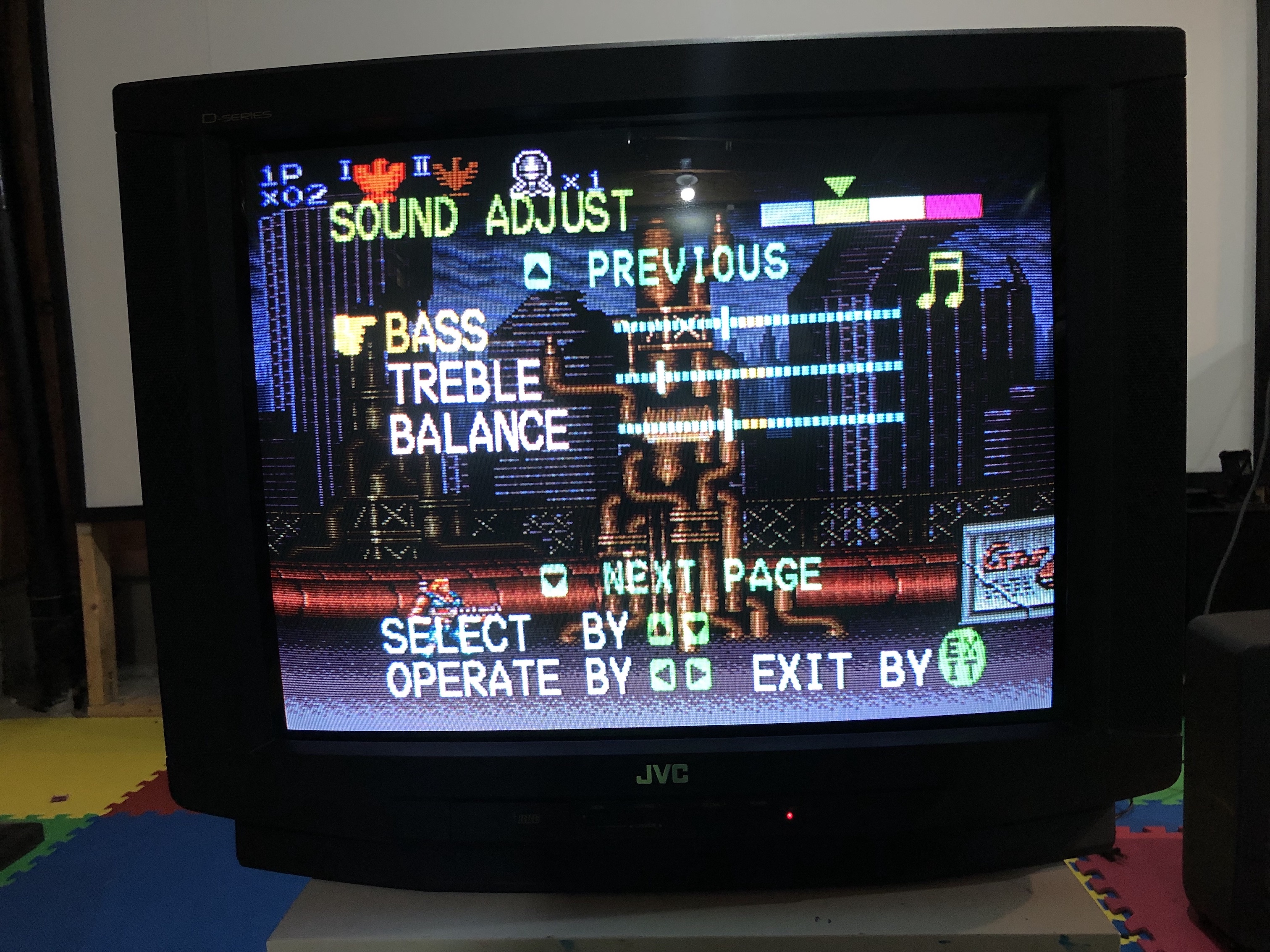
Games
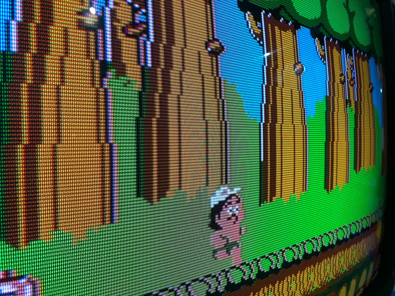
NES - Super Mario Bros 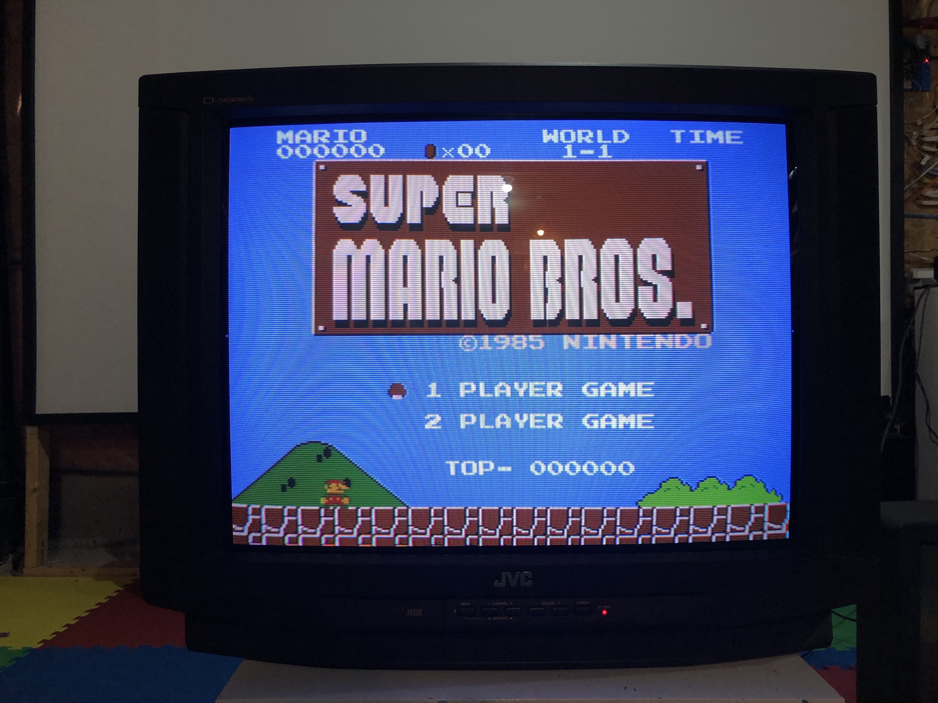
NES - Super Mario Bros (Close up) 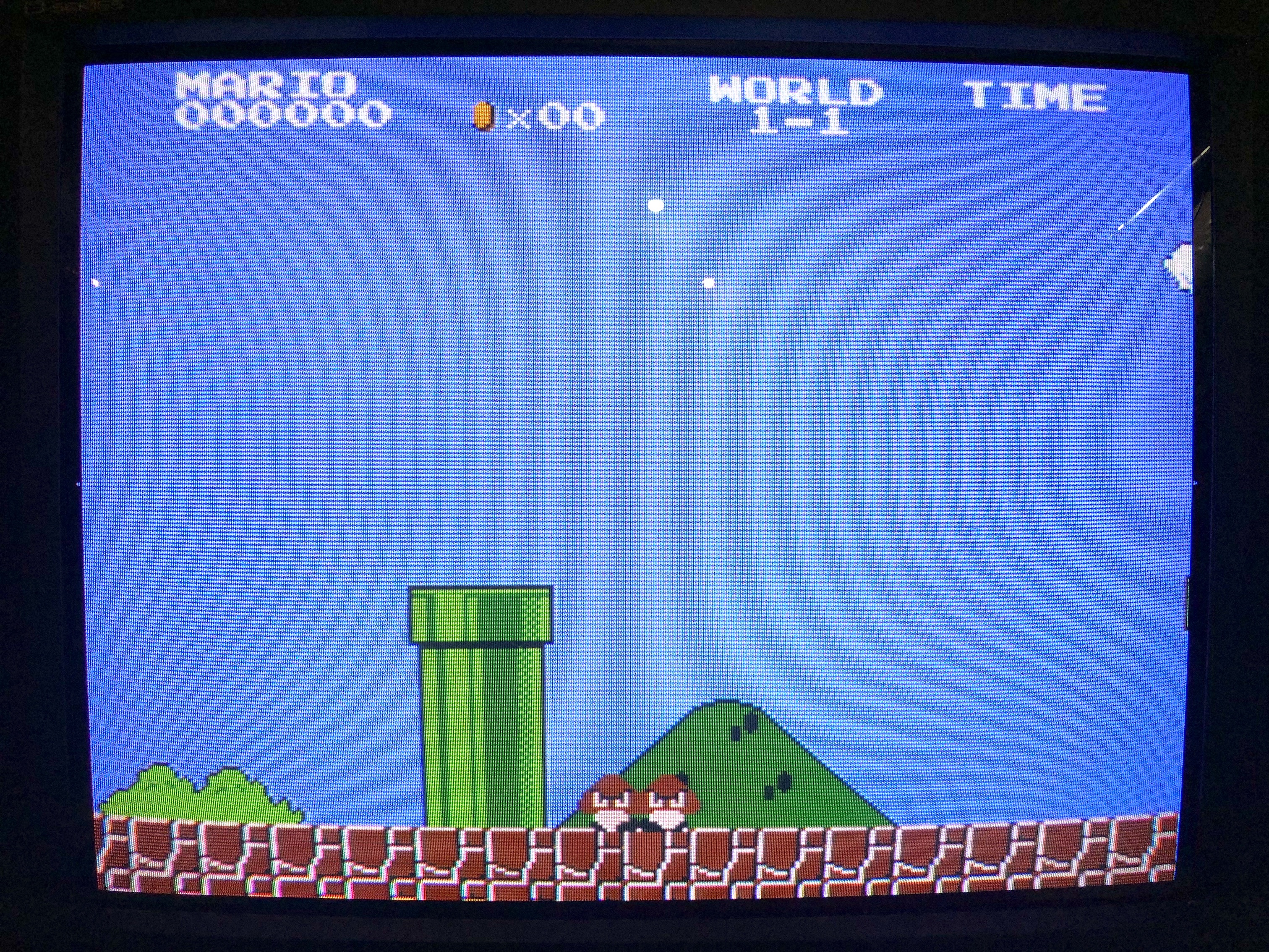
NES - Robocop 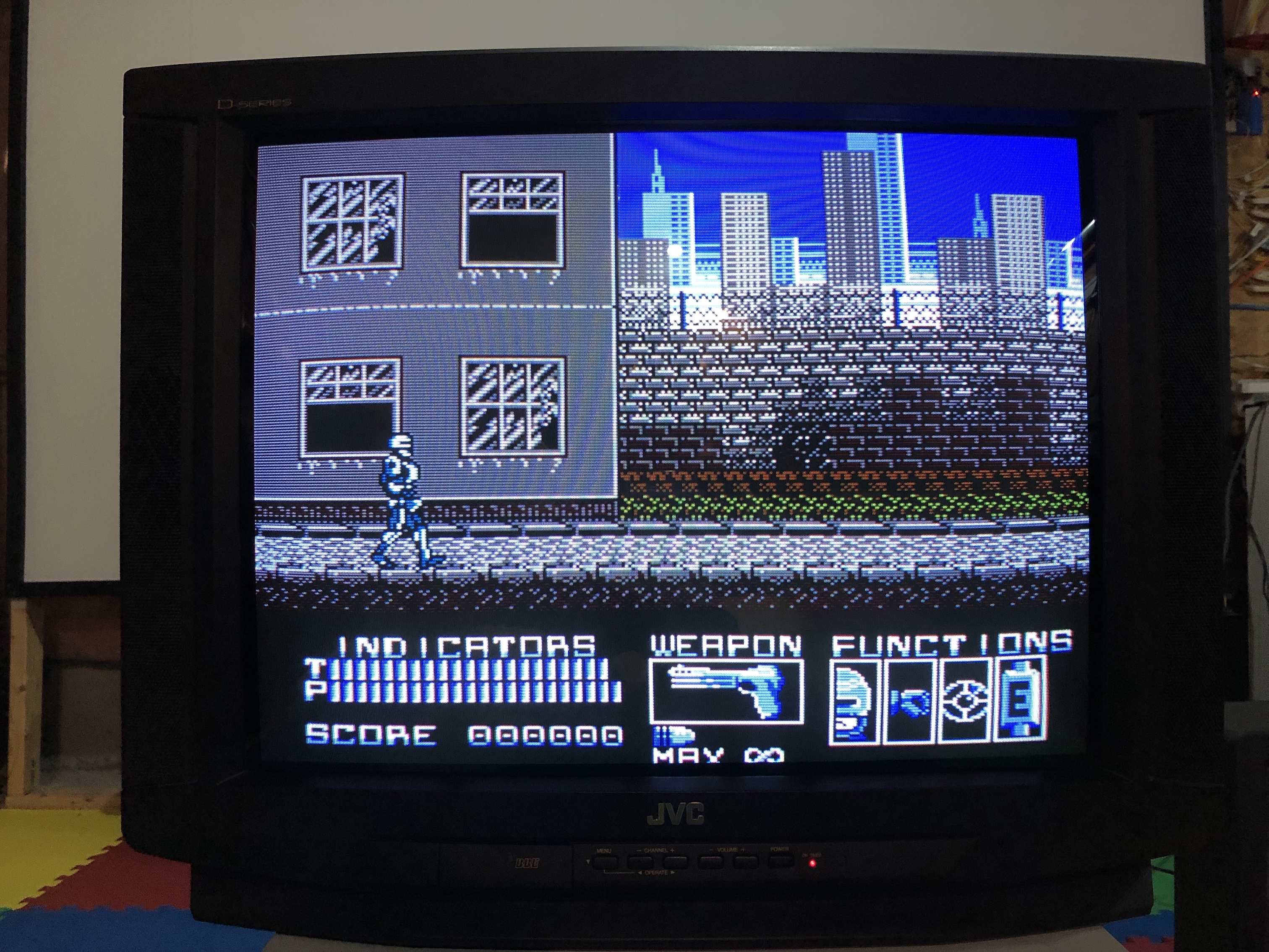
NES - Adventure Island 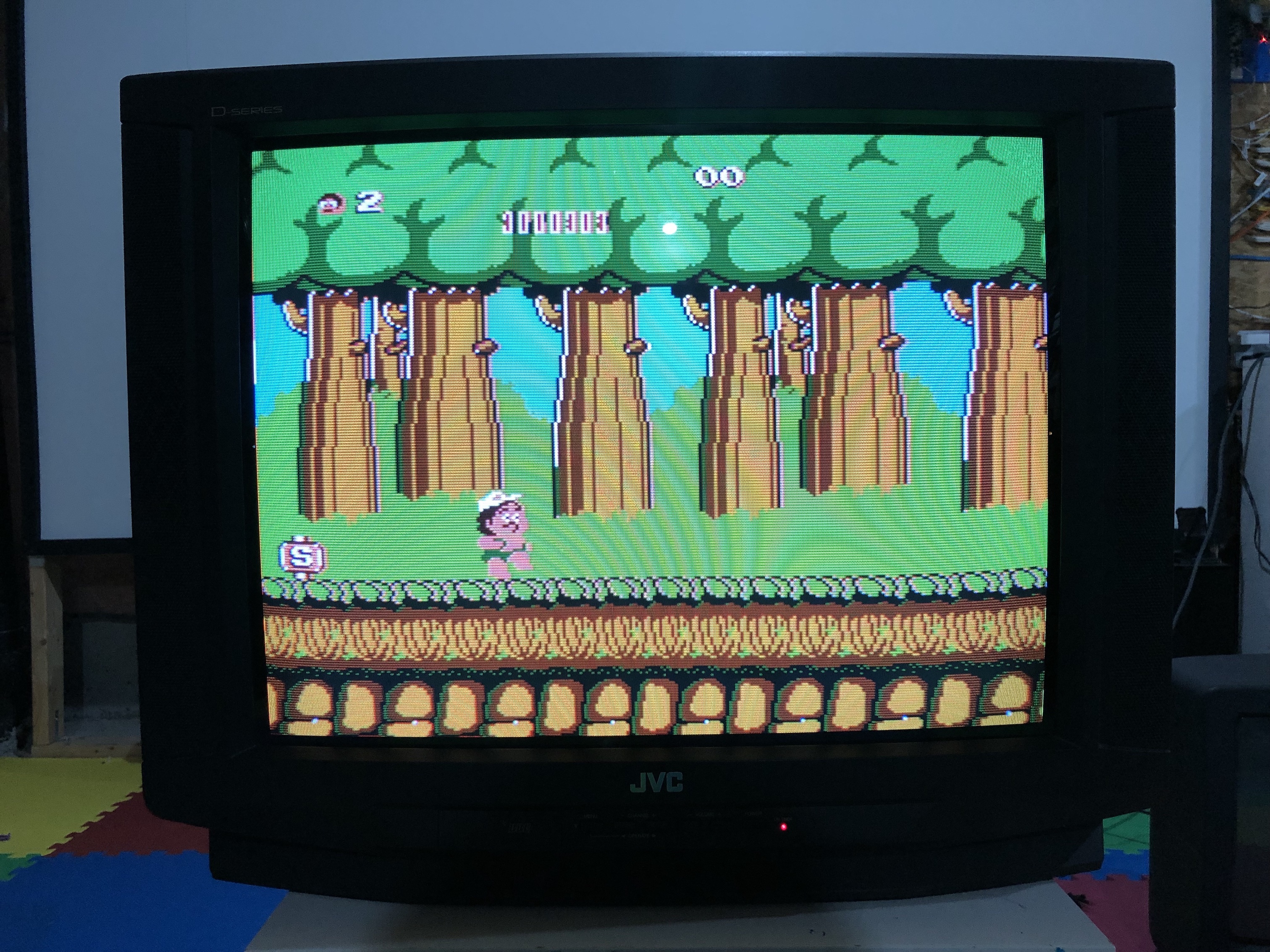
NES - Adventure Island (Close up) 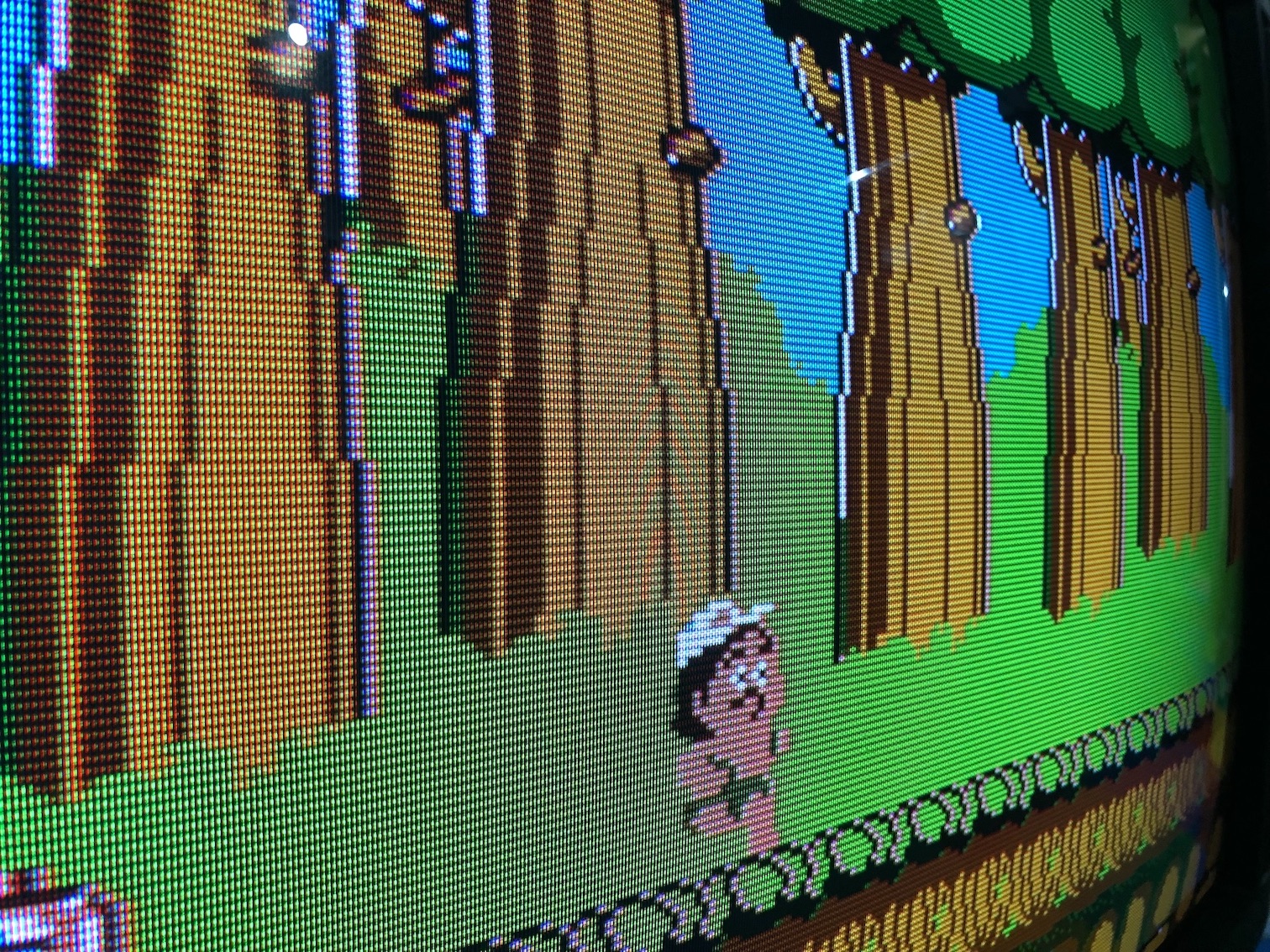
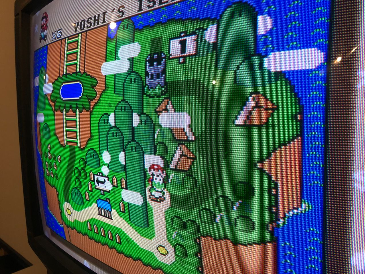
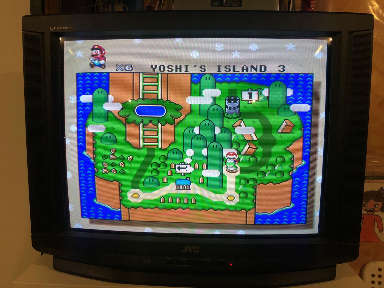
SNES - Yoshi's Island 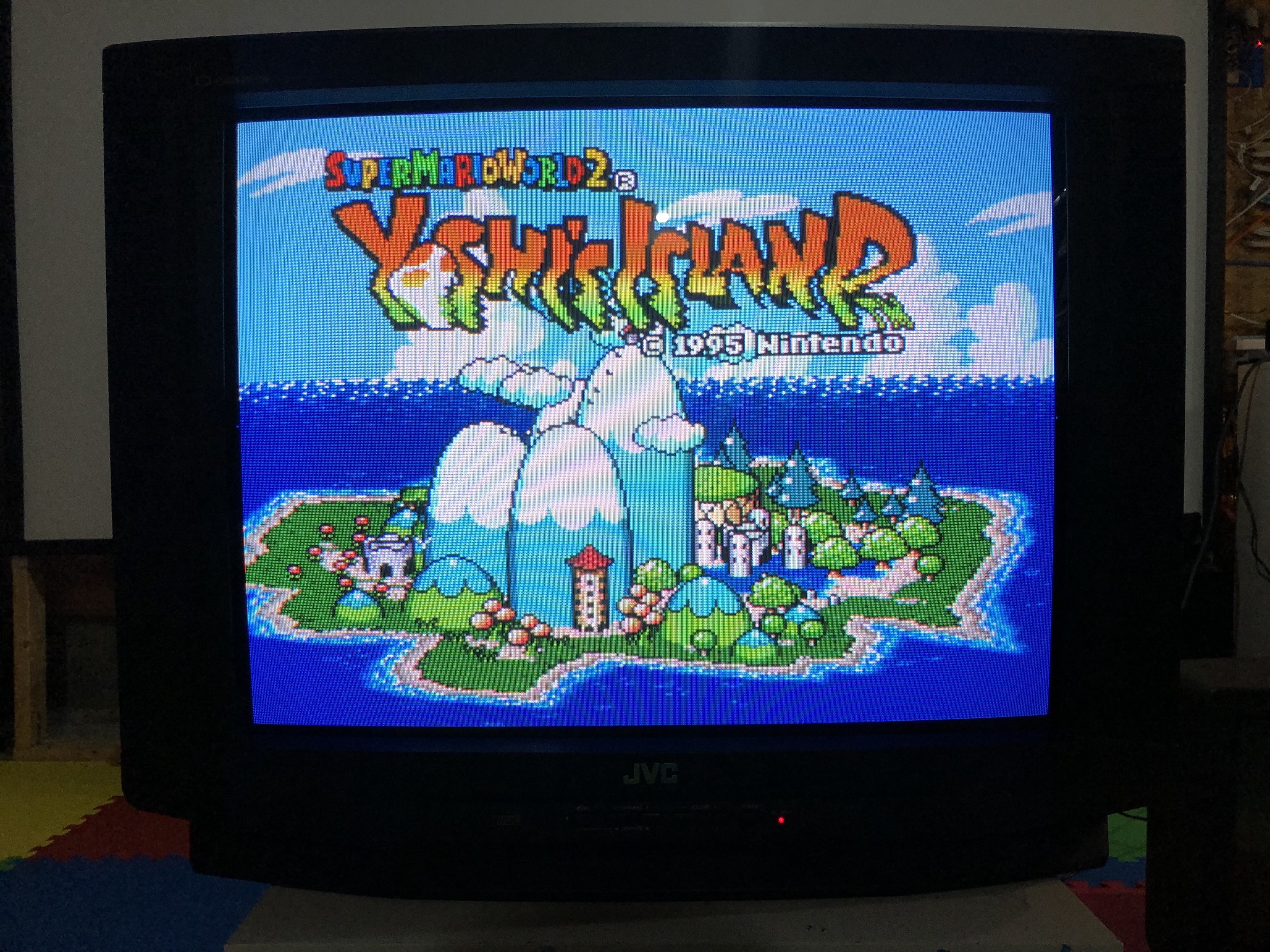
SNES - Super Metroid 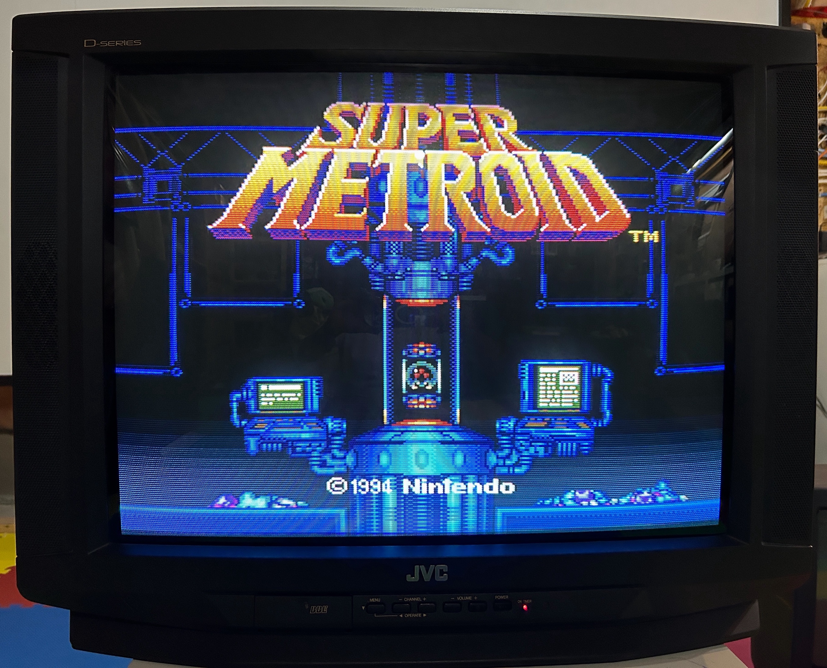
SNES - Super Mario World 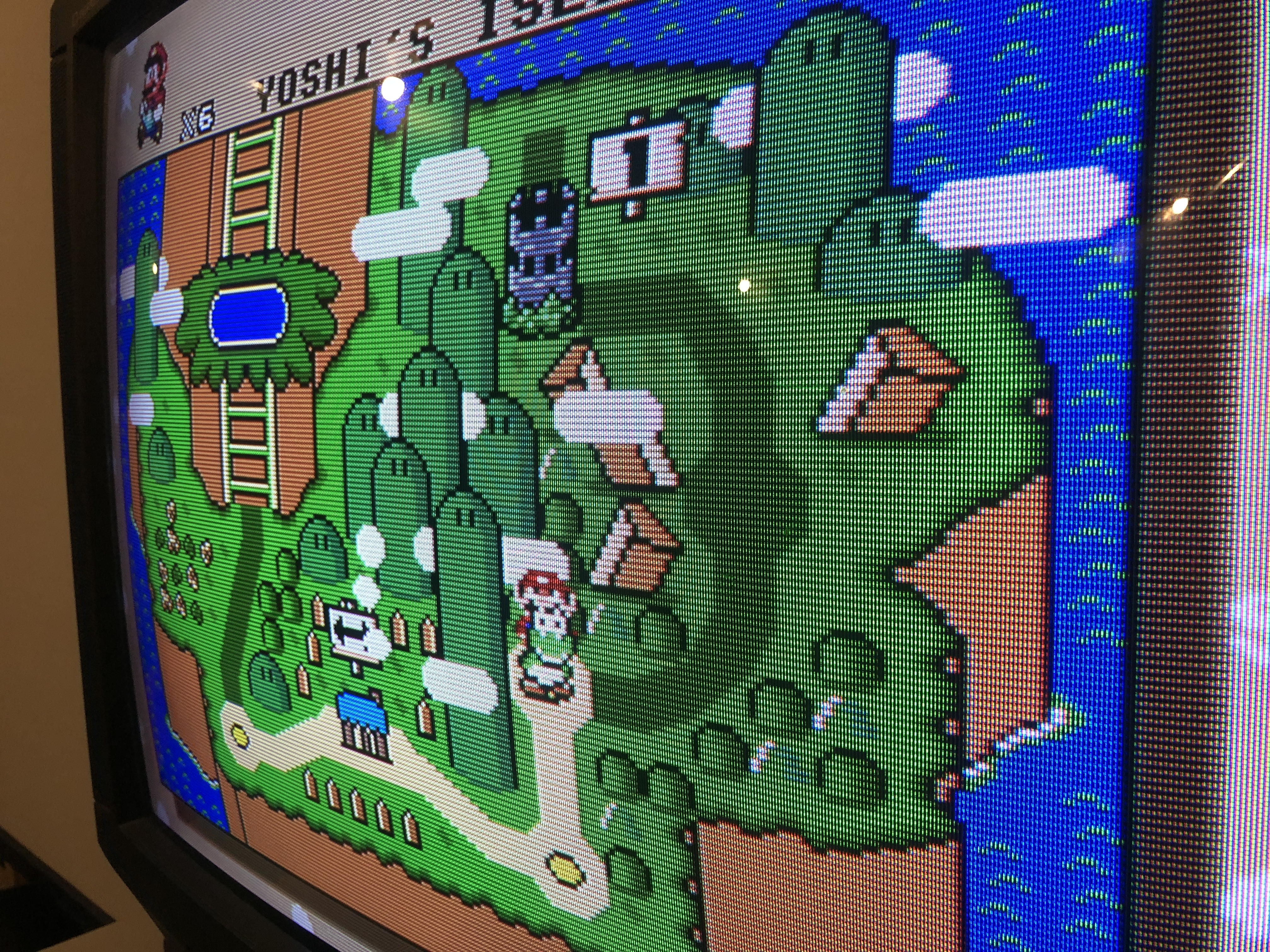
PS1 - Sony Logo 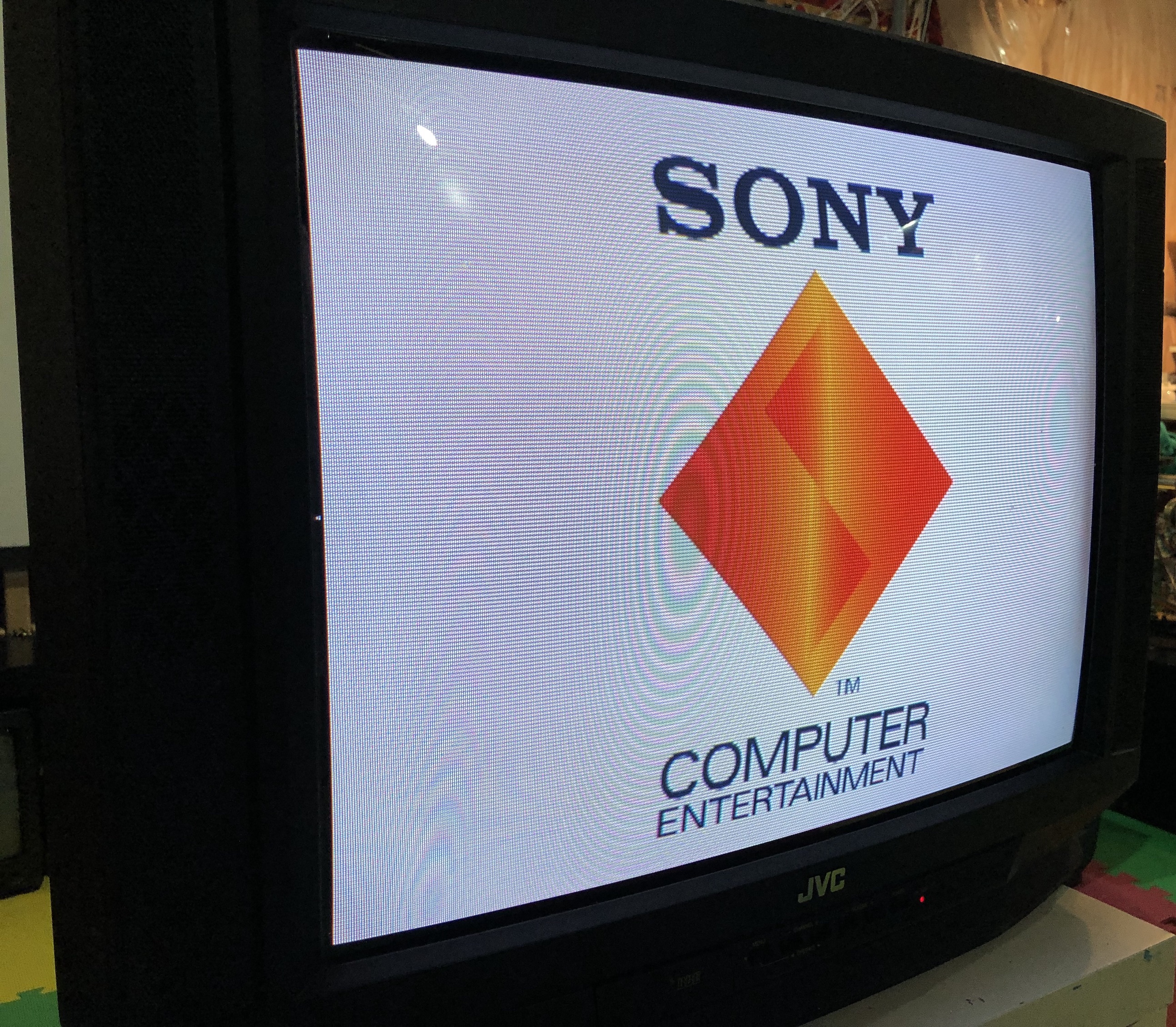
PS1 - Boot (close up) 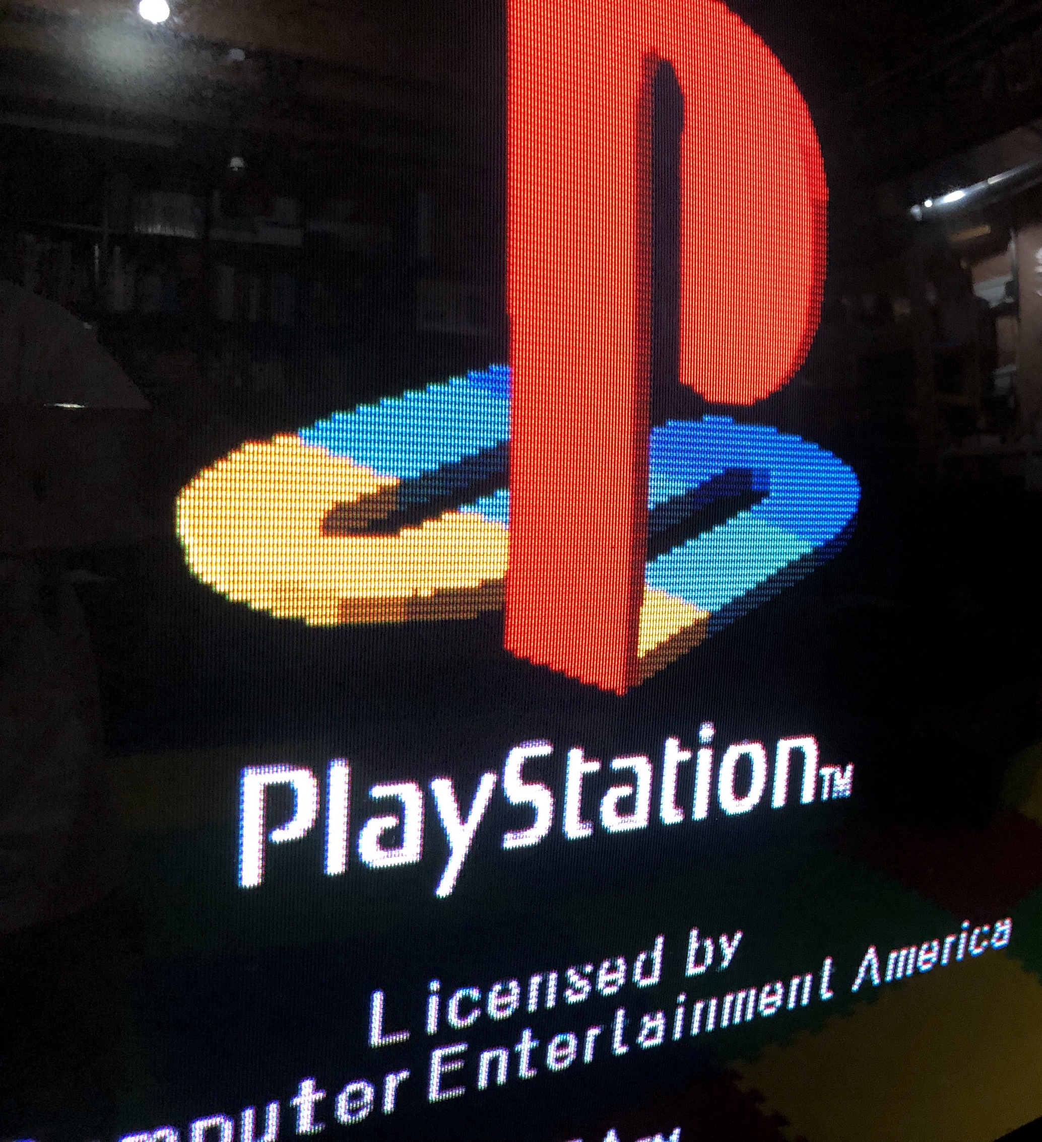
Wii - Just Dance 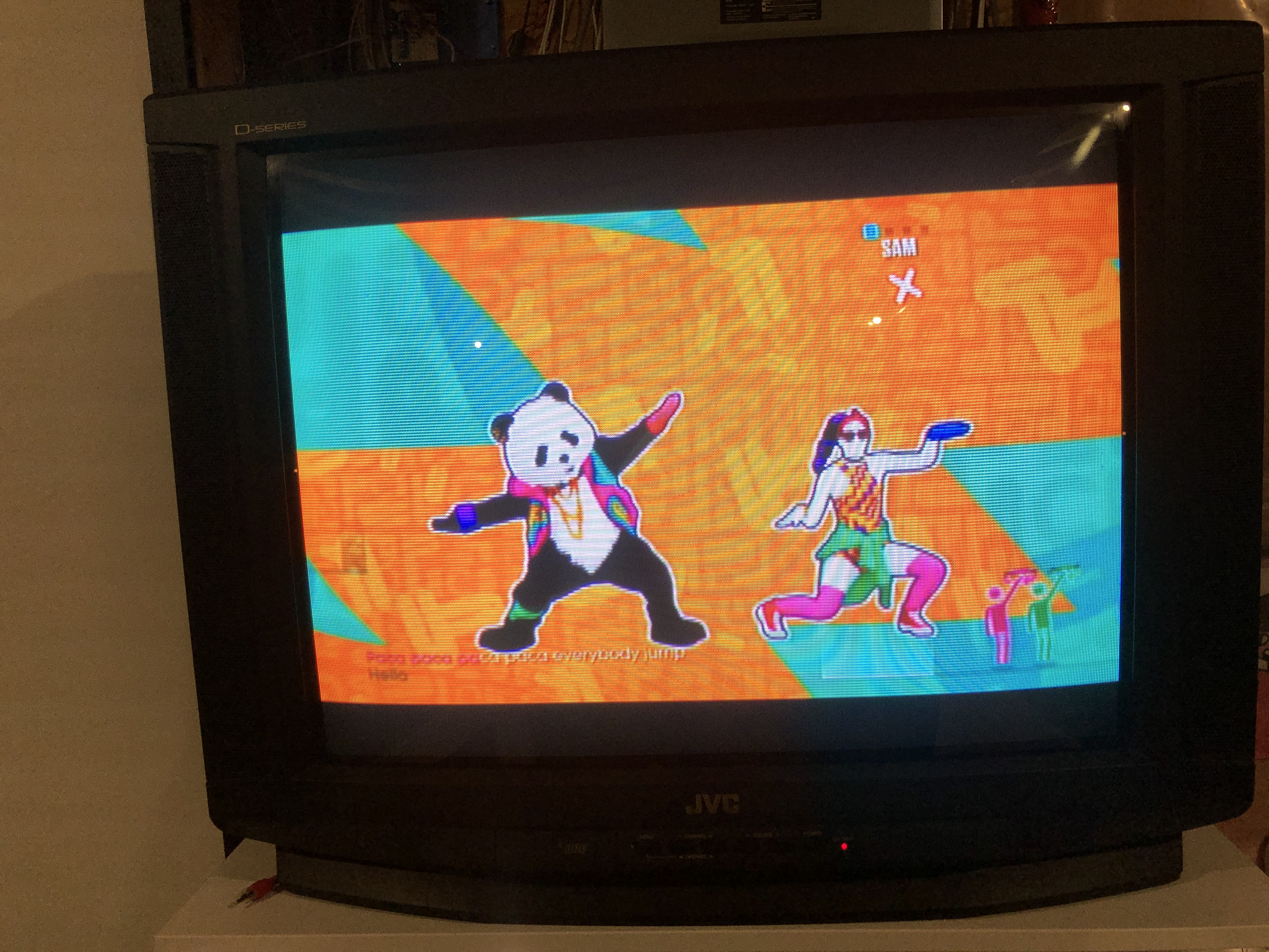
Sega Genesis 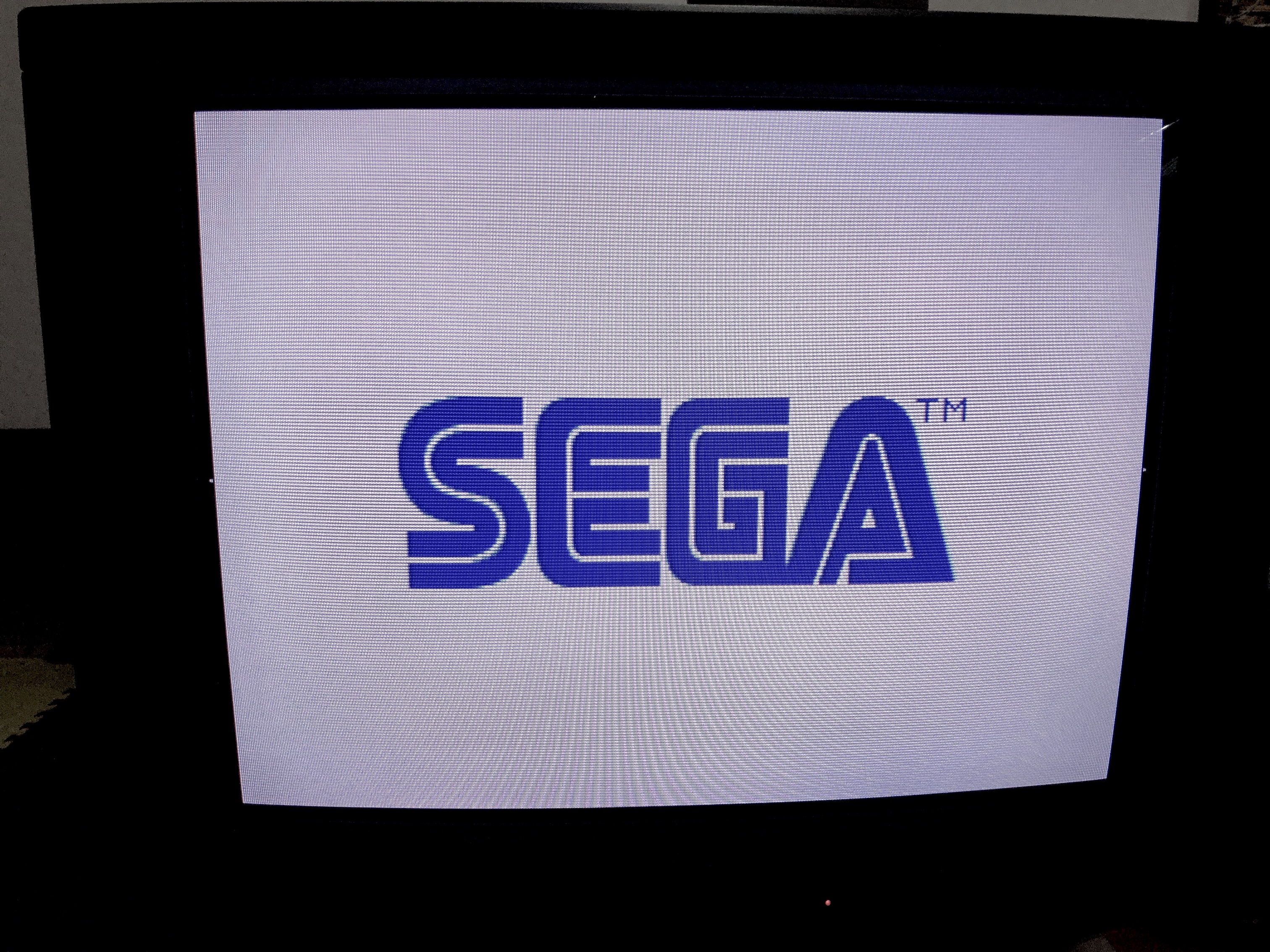
Patterns
Pattern - Grid 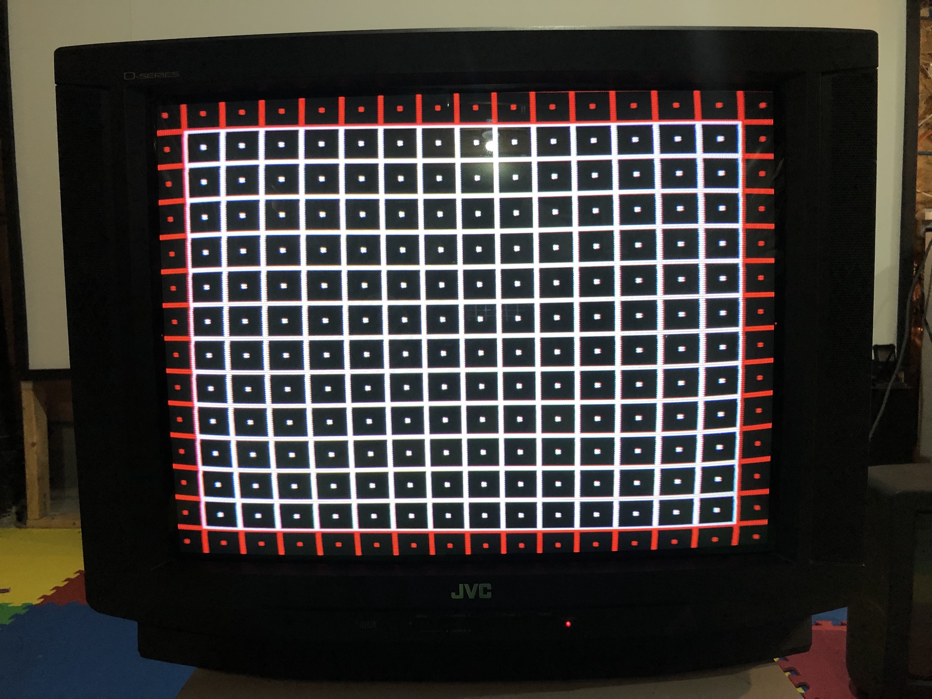
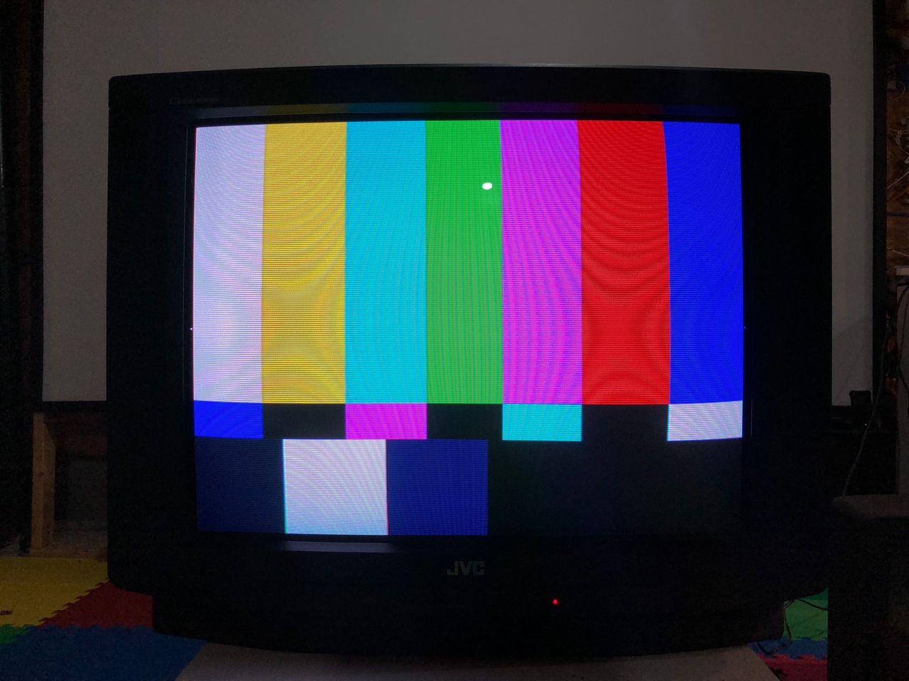
Pattern - SMPTE 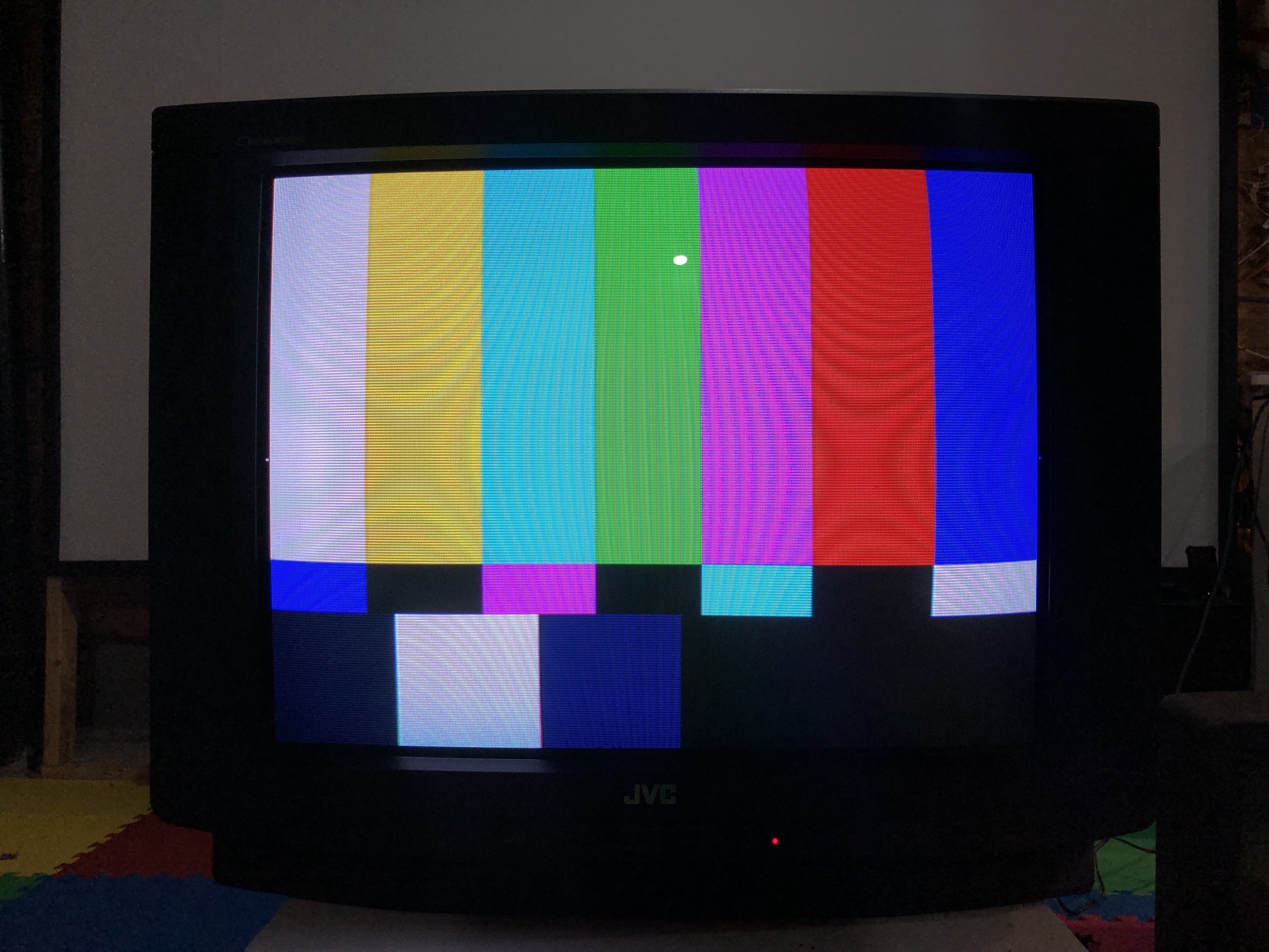
Grid/Geometry - before adjustment 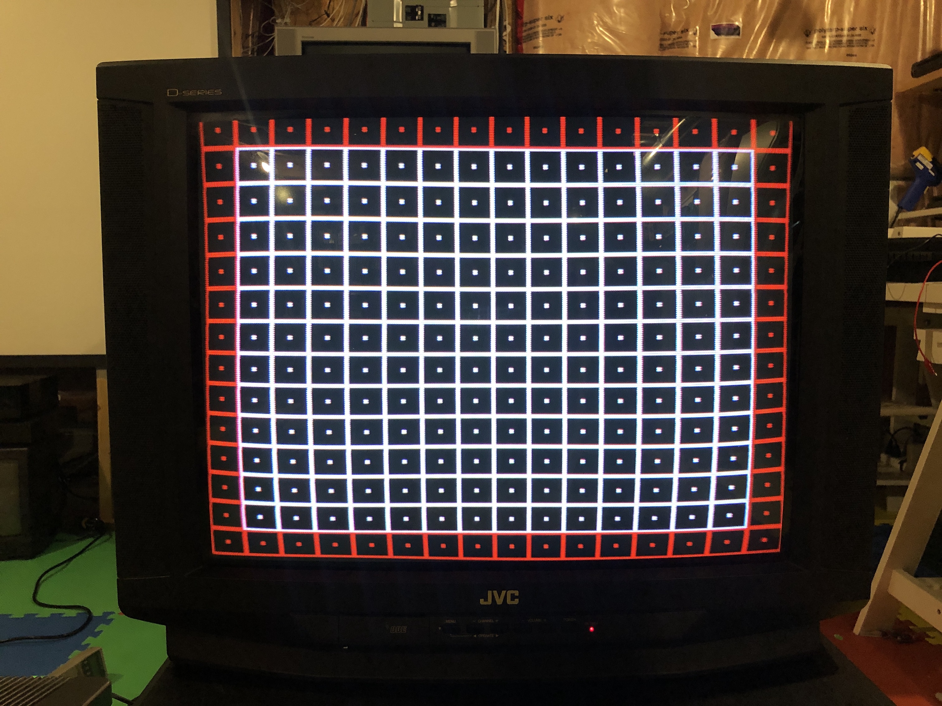
Grid/Geometry - after adjustment 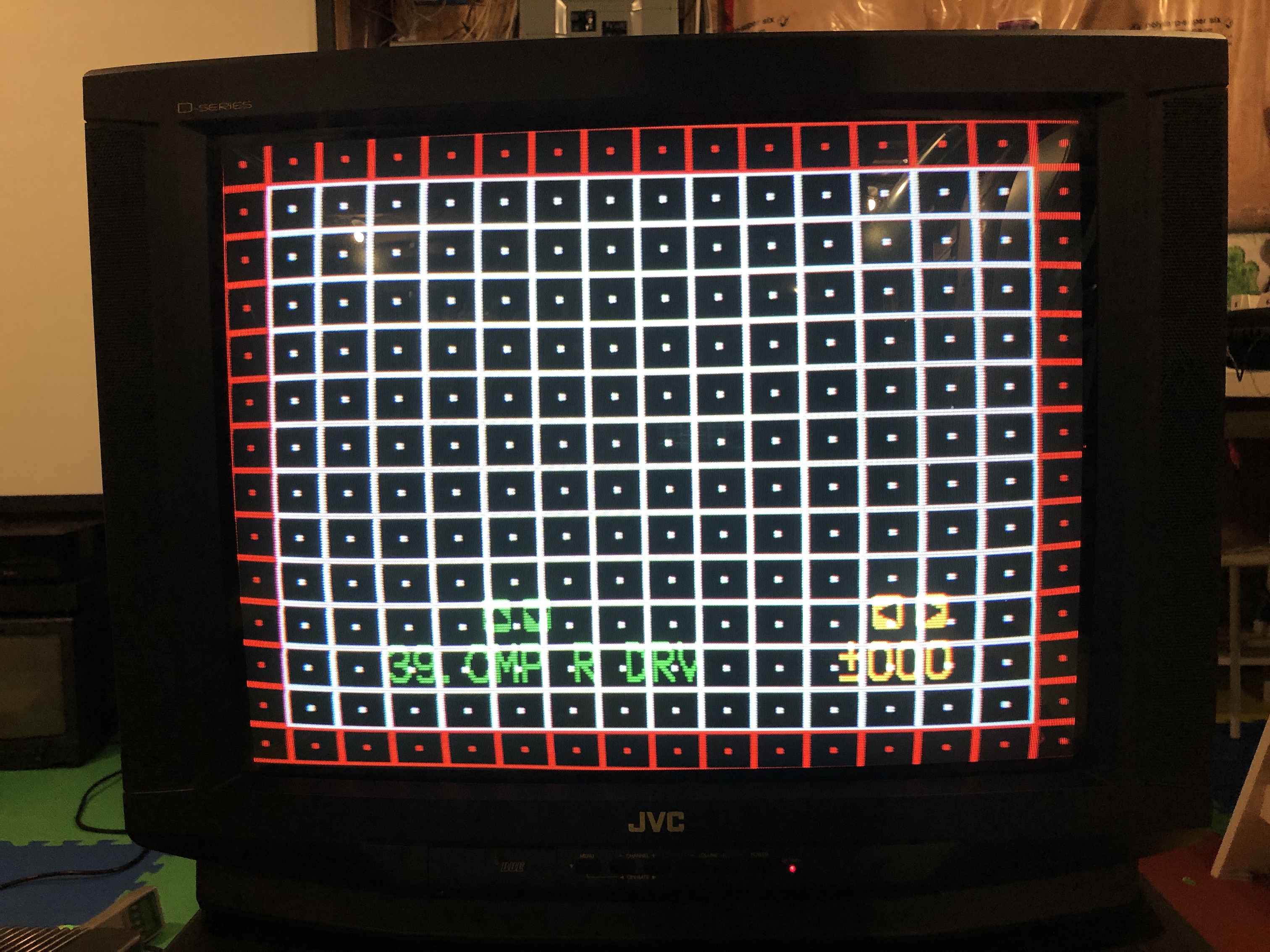
Flyback
Tuner board
Used the tuner board to fine tune the resistors needed for the RGB mod.
Tube
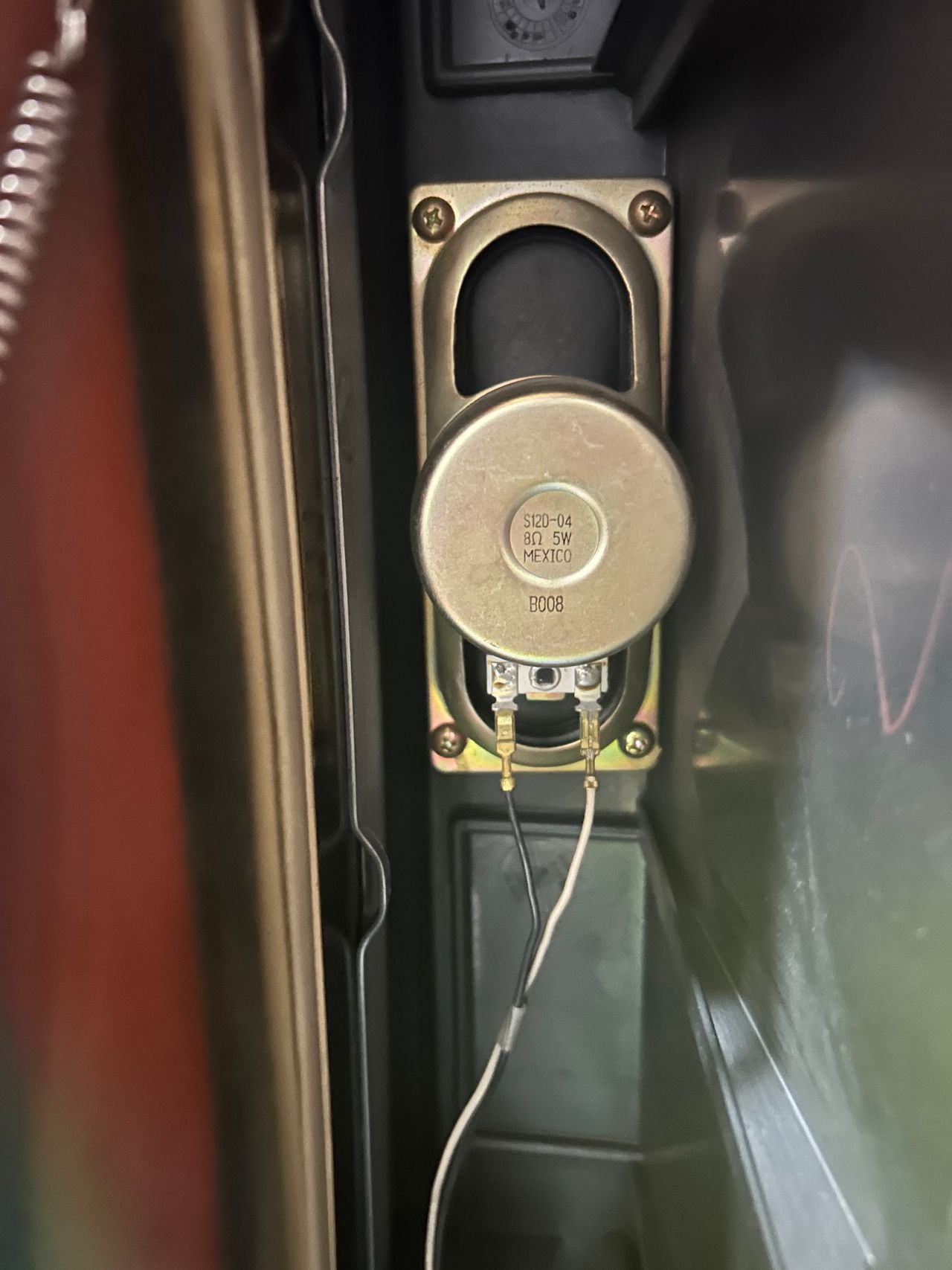
Speaker

Other CRT pictures
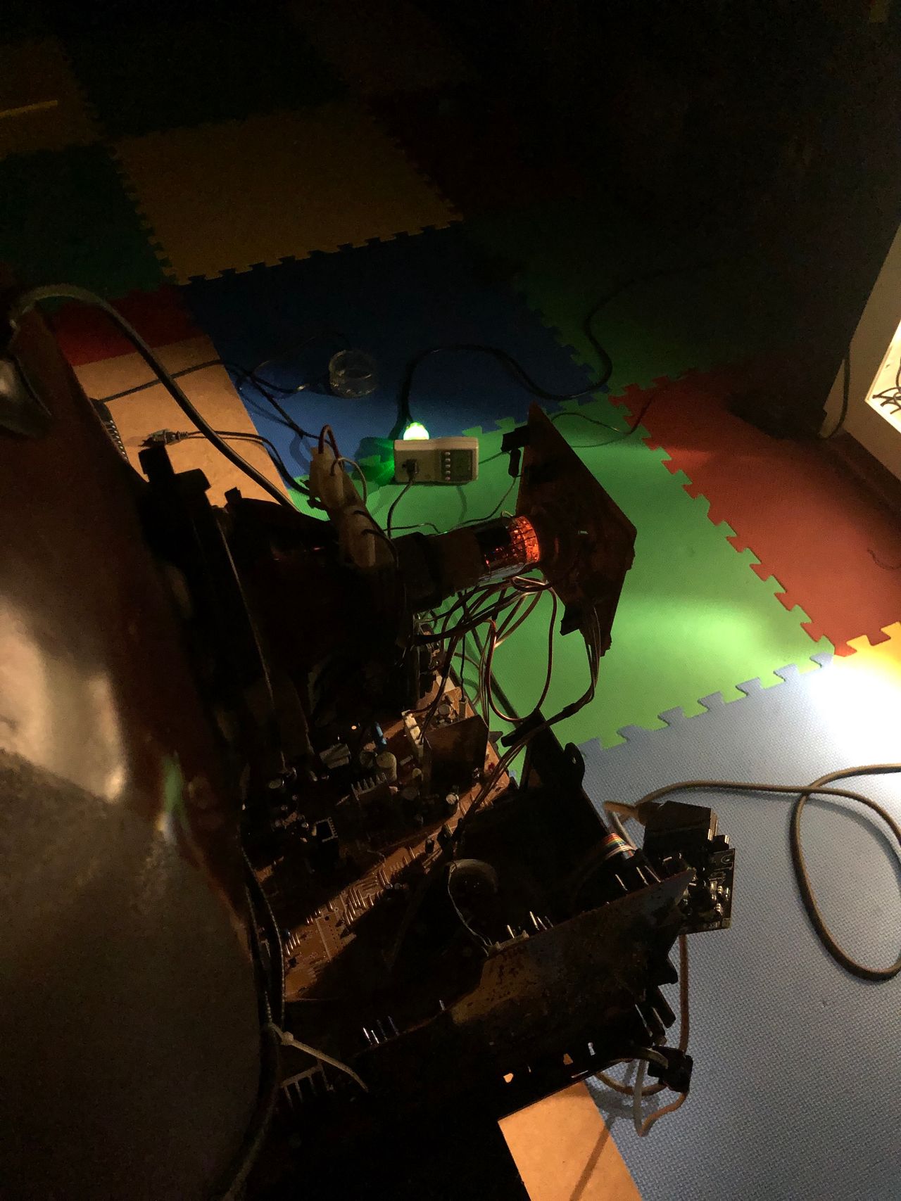
Glow from the cathode 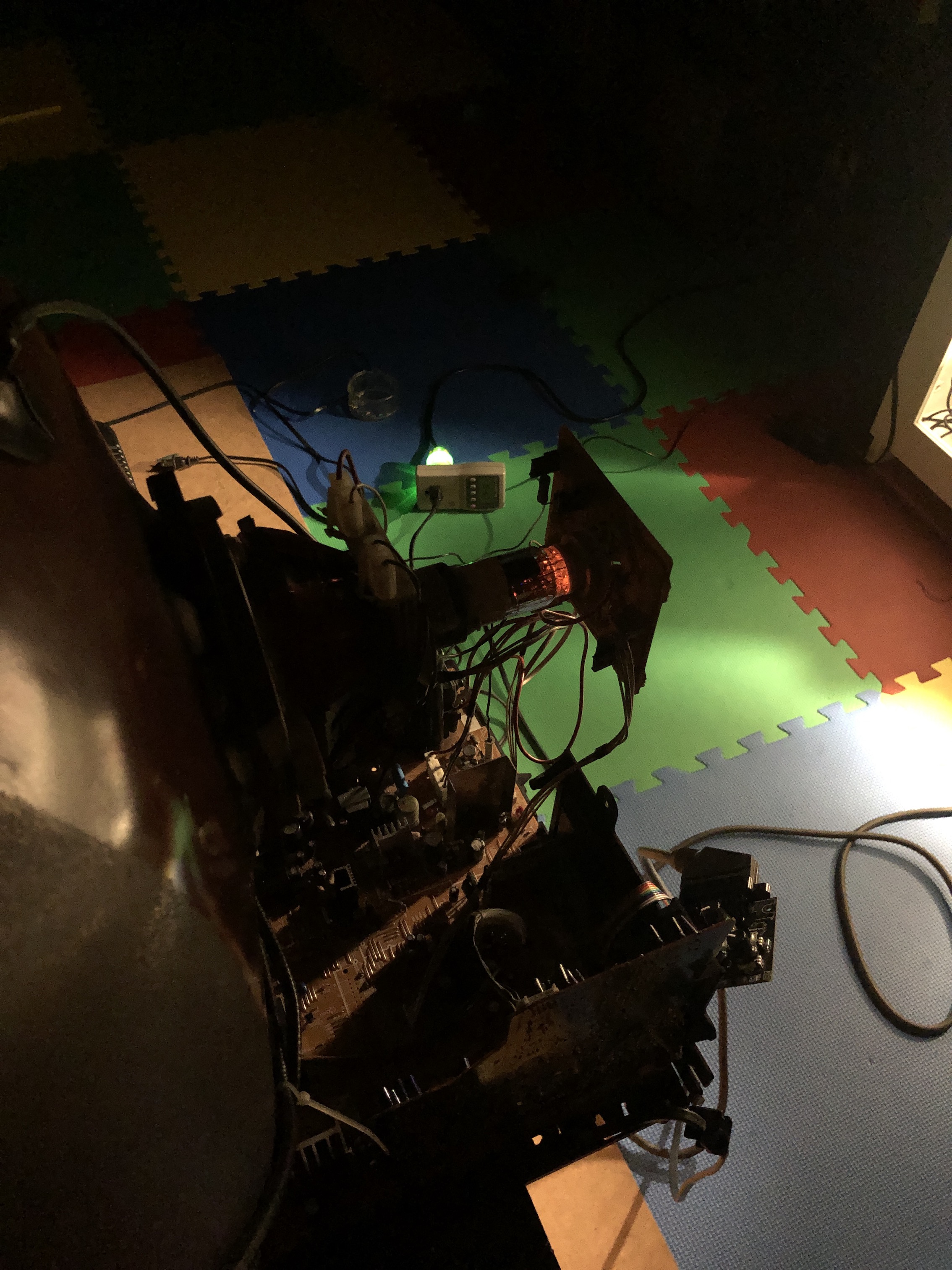
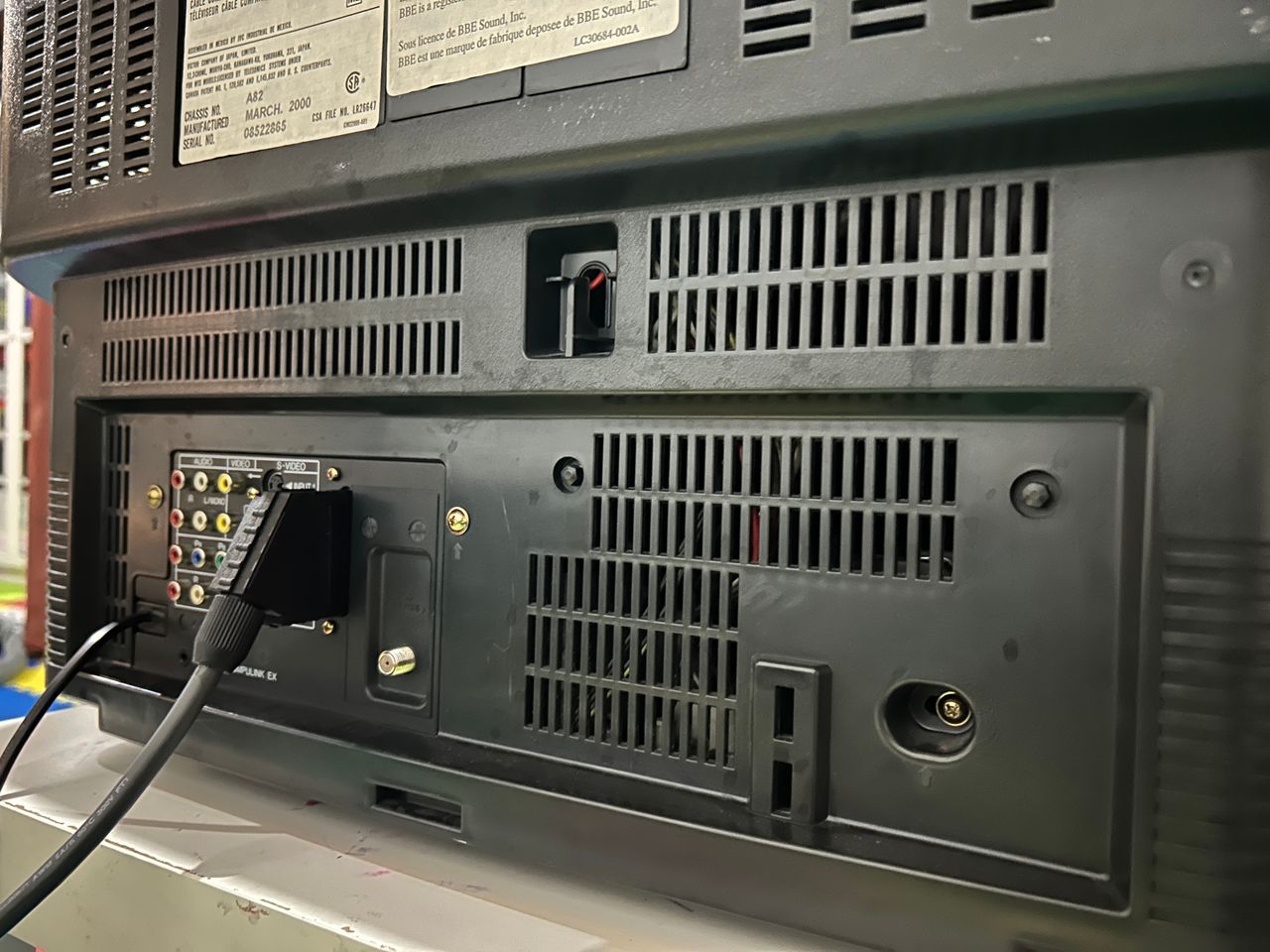
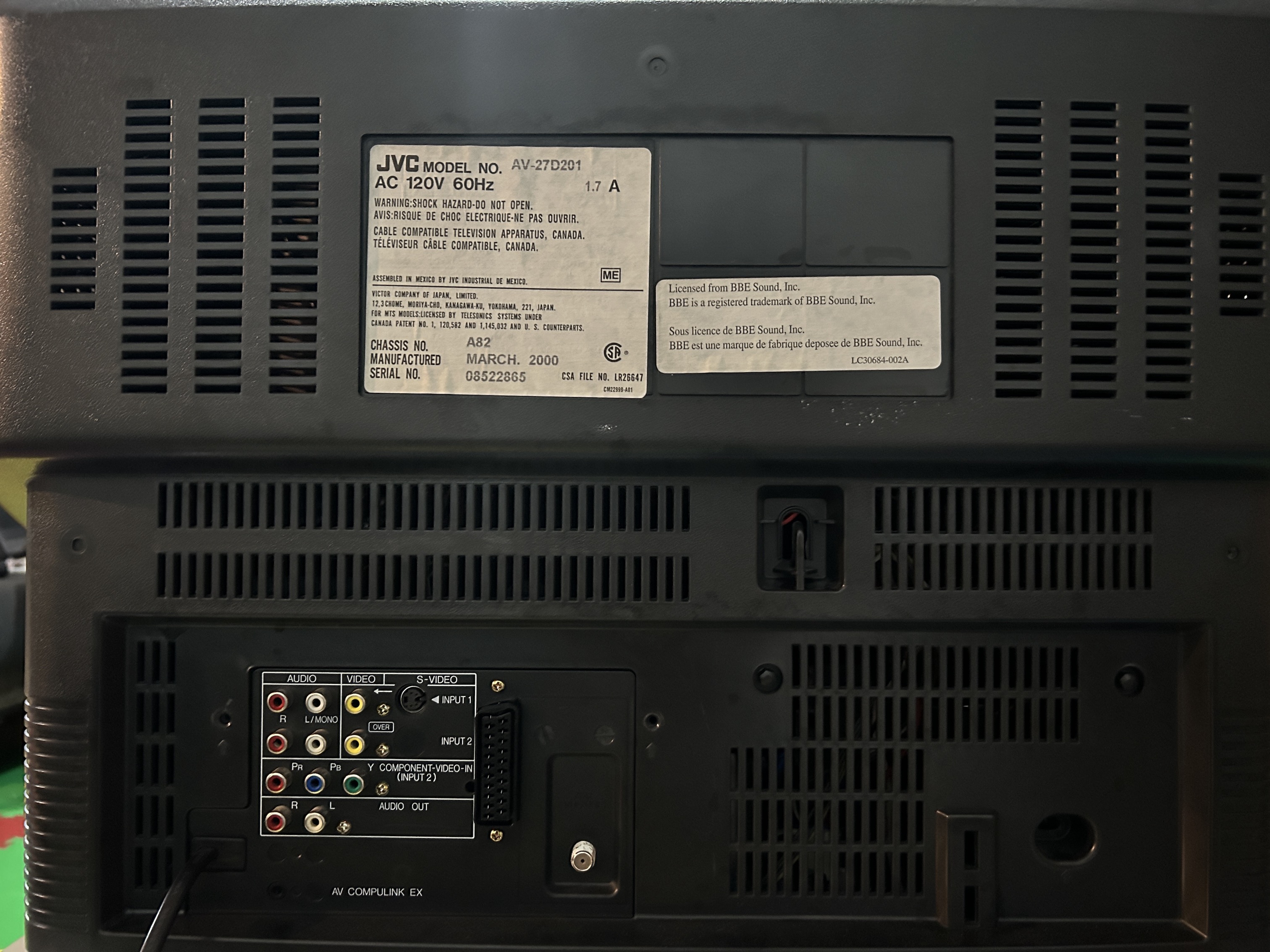
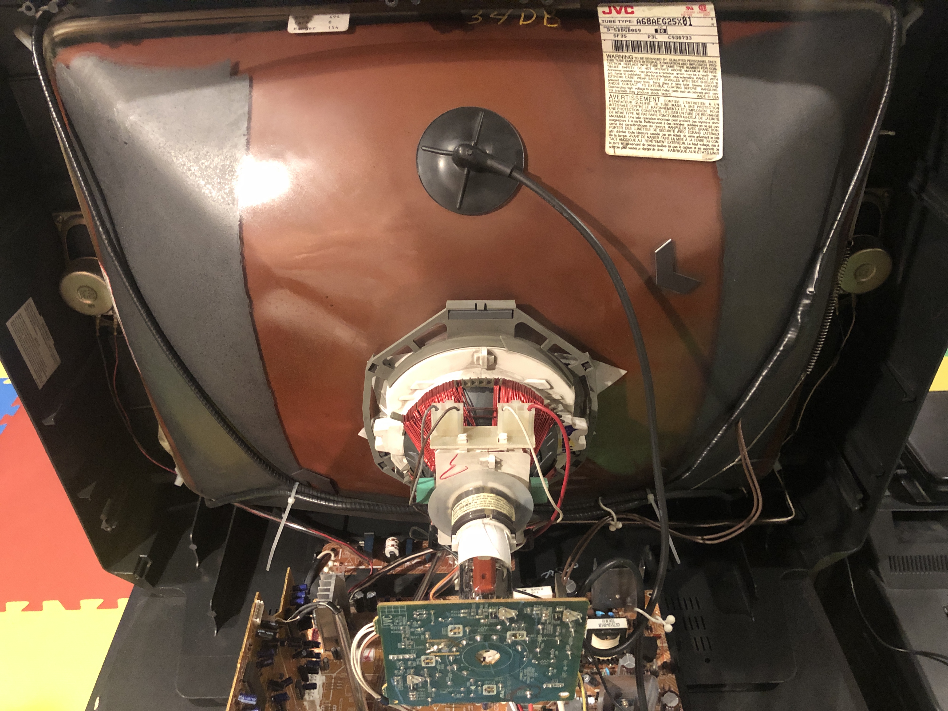
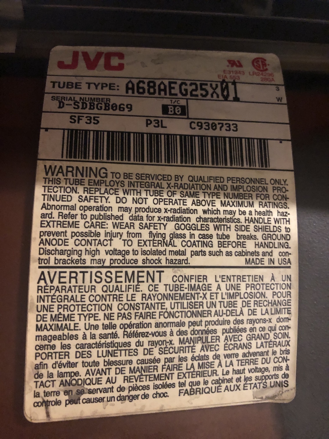
Back label 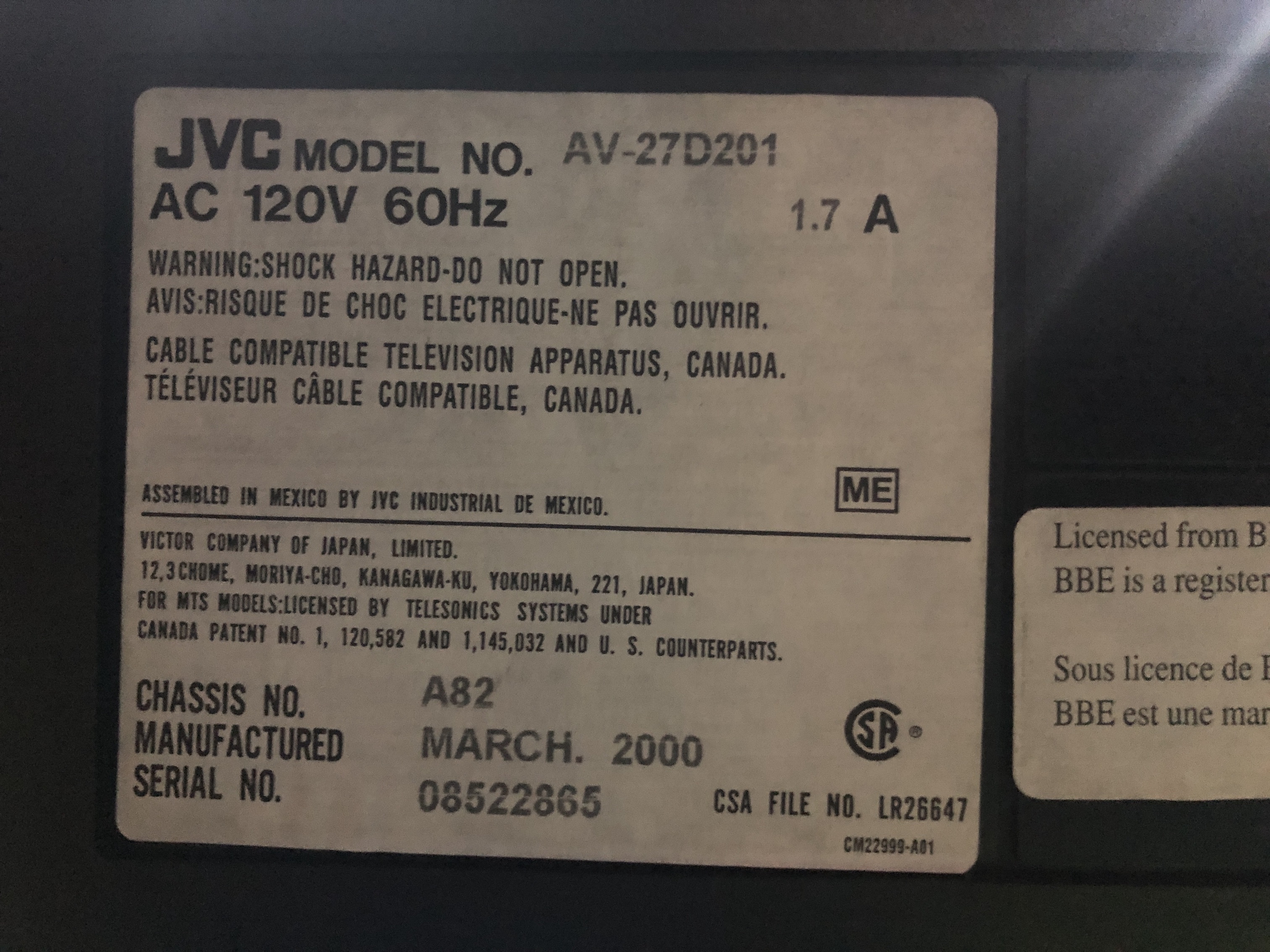
Front AV connector had to be reflowed 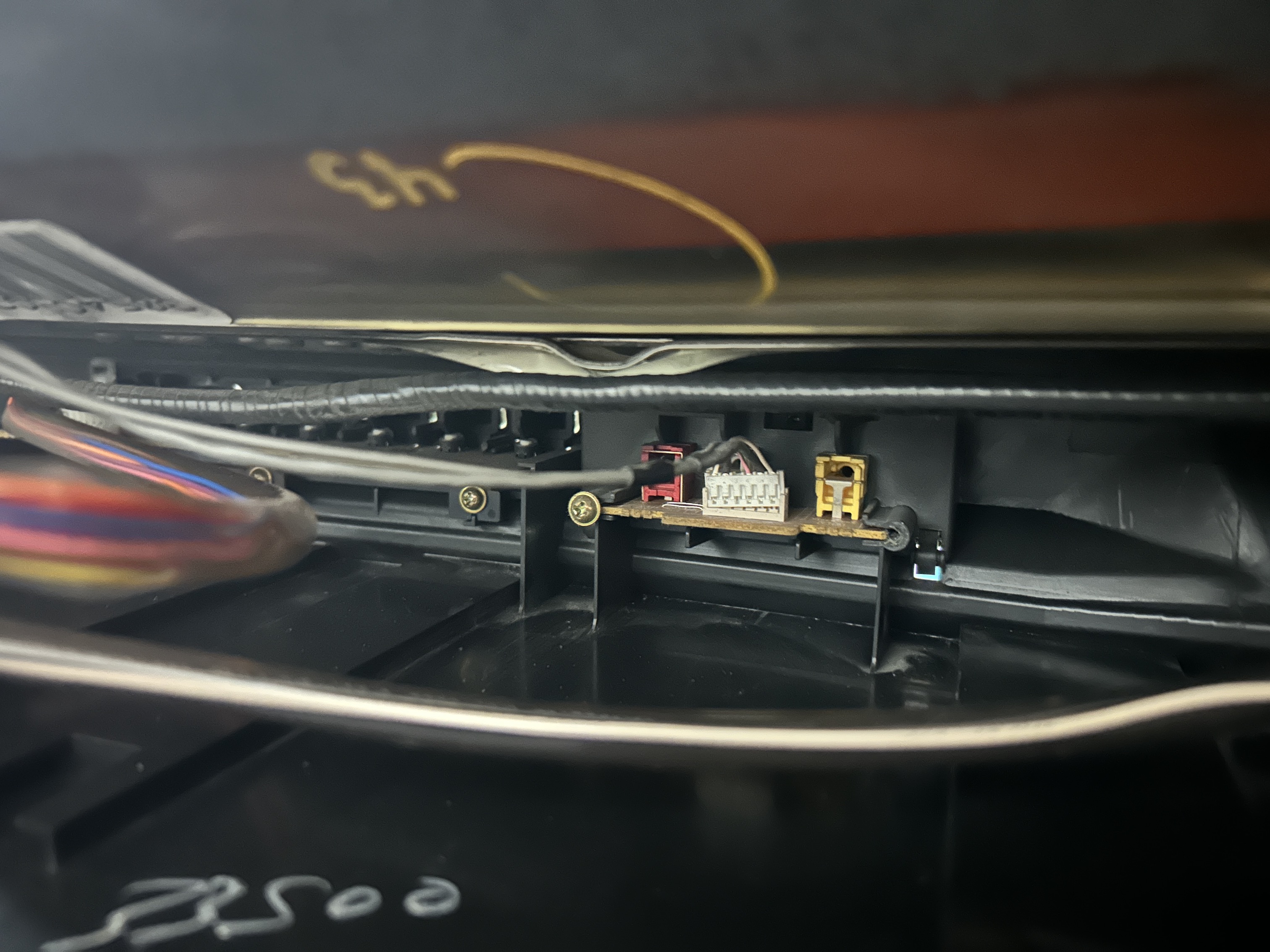
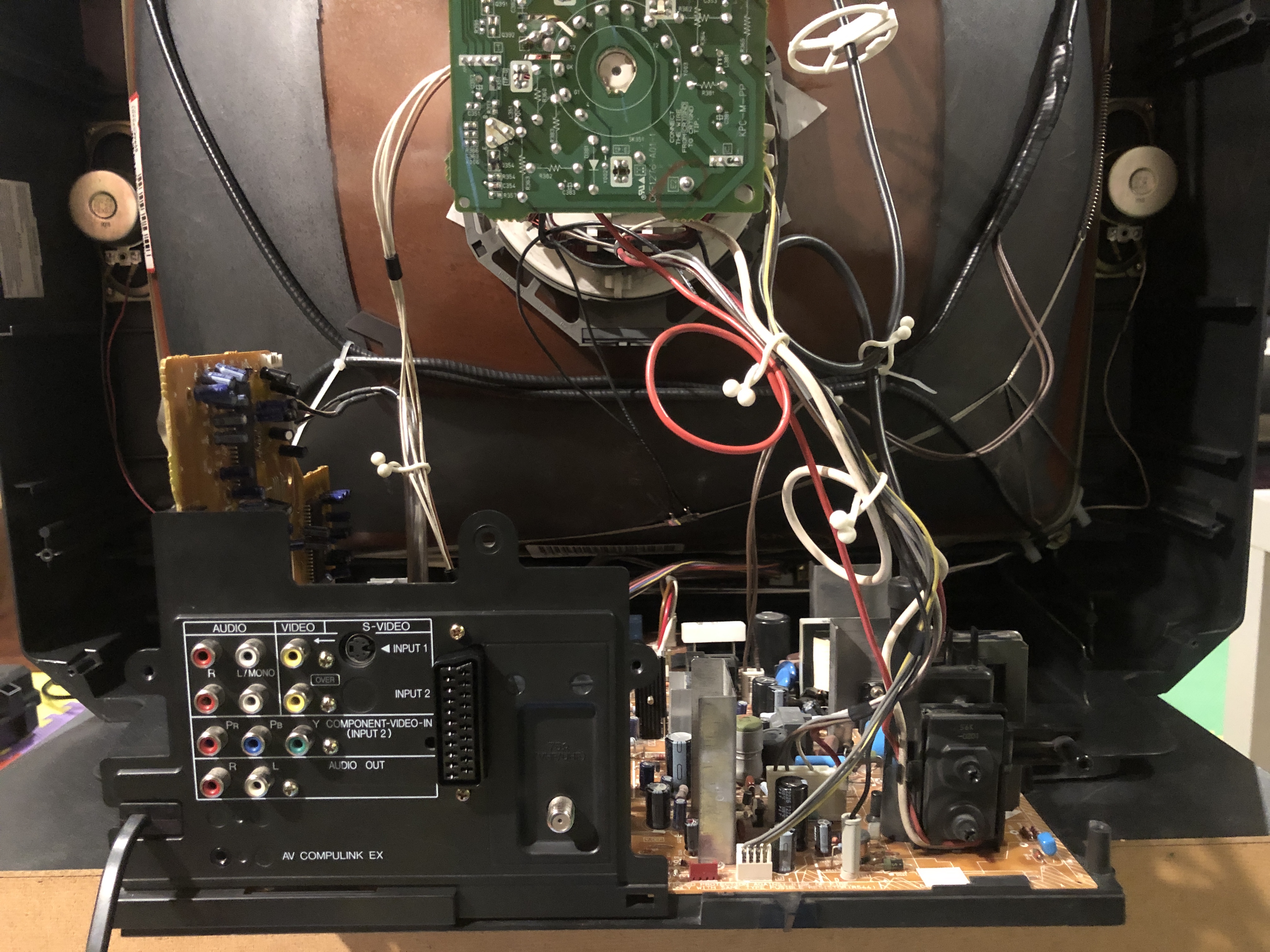
Back open 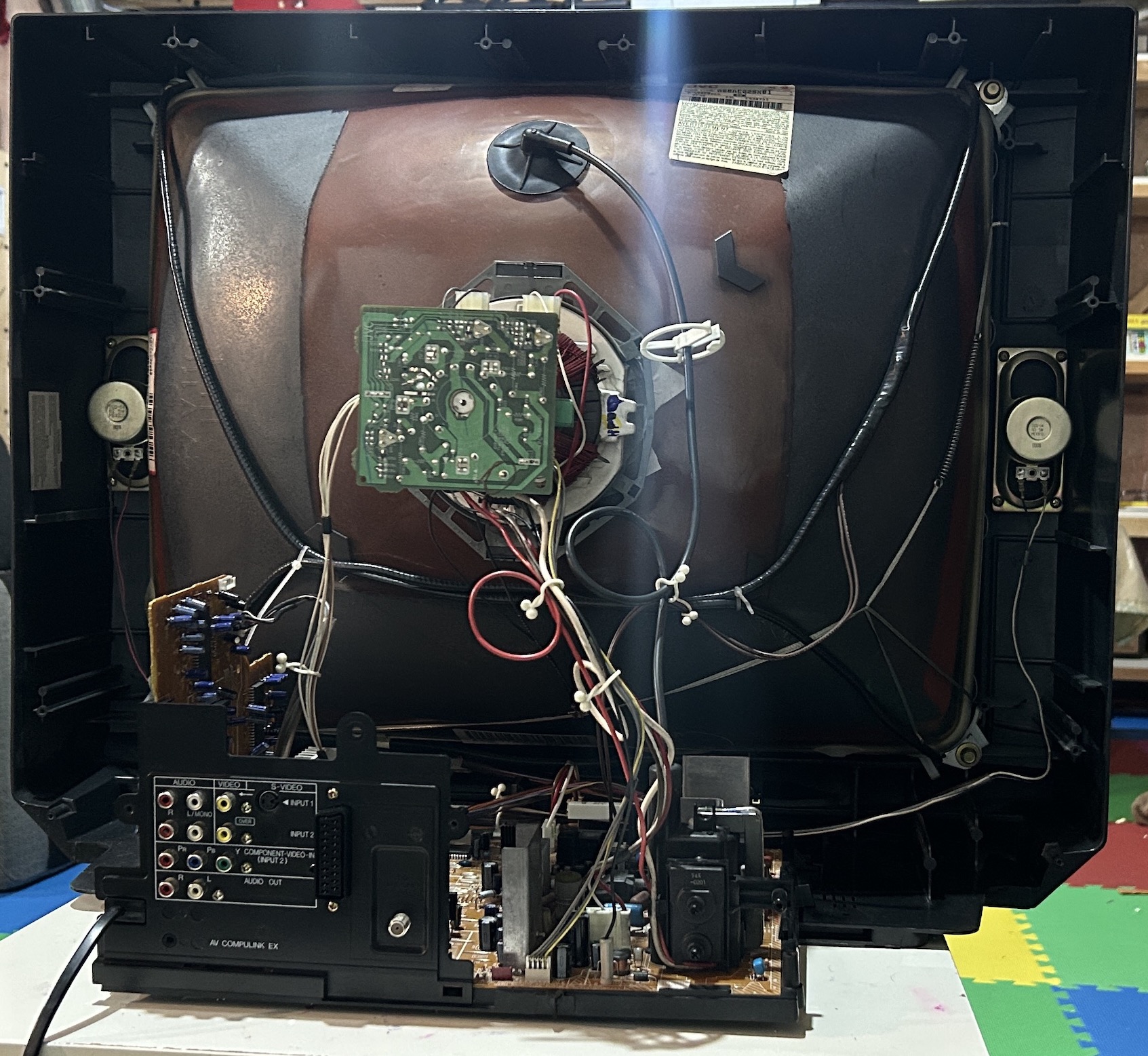
From the label, the tube used in this CRT, A68AEG25X01, is made in the USA. In addition, the tube, model number A68ADT25X01, was also used in many mid to late 1990s TVs from JVC, Samsung, Mitsubishi, and other brands.
A68ADT25X01 and A68AEG25X01 are not compatible
RCA Thomson A68AEG25X01 tube is confirmed to be found in the below CRTs
- JVC AV-27D200
- JVC AV-27D201
RCA Thomson A68ADT25X01 tube is confirmed to be found in the below CRTs
- JVC AV-27230 (Serial number at the back ends in an R)
- JVC AV-27320
- JVC AV-27330
- Sanyo DS27214
Please note other tubes can also be found in the above models.
32" Hitachi Tube
- A80LJF30X08
Issues
Funhouse scrolling issue
See discussion here. This is apparently fairly common on the JVC D-Series.
You can see the issue in the video below.
This funhouse missor issue is not severe in this particular JVC D-Series. If you are someone who cares about every single detail, this might be something that can be seen as bothersome. According to /u/r1ggles, modifying the horizontal deflection circuitry might help improve this. They also suggest a recap of the deflection circuitry before trying anything else.
Replace the film caps for the chassis, do a full recap for the end of scan squash (right side of the screen shrinkage). For the squashed center you'll have to try with different s-correction values, in the comparison video between the flatter tube it's still pretty bad, there's still "fun house" distortion going on there, just less due to the scan moving faster at the edges than in the center due to deflection angles of the edges being further away.
The S-Correction cap (a film cap that's usually in the 400nF range) is meant to fix this, sometimes these were just off from factory, other times they've aged. Replacing film caps is a bit expensive, just a heads up, so don't let that be the first thing you do, just replace the s-correction capacitor. Has to be metallized polyester, ceramic or whatever substitutes despite their voltage rating being comparable will just burn up and likely take out a transistor in your horizontal deflection circuit with it.
Seeing as the issue is center squash rather than edge I'm going to guess it's just bad from factory, I'd try a film cap that's ~40nF less than default to start with. You can also put small 10nF film caps on a small board in parallel with the main one to experiment with different values, for example if the factory one is 400nF, you can get a 340nF film cap and a few smaller 10-20nF caps to find the geometrical sweetspot with.
What the S-Correction capacitor does is that it changes the start and end speed of each scan, (think of the horizontal deflection signal as a sawtooth shaped signal, where it draws each horizontal line at a constant speed from left to right across the screen, but since screens have the edges further away and at an angle compared to the center of the screen you need an S-shaped sawtooth that can compensate the curvature and draw the beam slower at the edges so that it matches the speed it draws the beam at the center of the screen, more of an S-shape means a slower start and slower end).
The S-Correction capacitor can be identified pretty easily with some effort, it has to be in the horizontal deflection directly in line with the in or out of the yoke connector (horizontal deflection coil of the yoke), in parallel with this film cap you'll have a small ceramic capacitor and a small resistor (they're there to lessen an effect called parasitic capacitance).
Pictures
Reference Photos