Sony (ANU-2) KV-27EXR20
Sony (ANU-2) KV-27EXR20 CRT RGB mod
The Sony KV-27EXR20 is a premium 27" CRT television released in the early 1990s, built on Sony's renowned Microblack Trinitron picture tube technology.
This CRT is RGB moddable using the direct injection method.
View full CRT details and more mod examples →
This RGB mod applies to the following models. Other ANU-2 chassis can also utilize the same mod.
- KV-20EXR10
- KV-20EXR15
- KV-20EXR20
- KV-27EXR10
- KV-27EXR15*
- KV-27EXR20
- KV-27EXR25*
*The P-Board for Picture-in-Picture functionality must be removed in these models.
Contributors
Thank you to everyone who contributed to this guide:
- Kaz Packman — contributor, RGB mod and pictures
CRT safety
Caution
You can die doing this! So read carefully! CRT TV is not a toy. Do not open a CRT TV. If you don't have any prior knowledge about handling high voltage devices, this guide is not for you. CRT TV contains high enough voltage (20,000+ V) and current to be deadly, even when it is turned off.
Plan of attack
Manuals and Datasheets
Specs
- Manufactured: Mexico (1992)
- Chassis: ANU-2
- Tube: Sony Microblack Trinitron A68JMT50X
- Jungle Chip: Sony CXA1313S
- OSD Chip: M37100M8-115SP
RGB mux diagram
Prepare the mux diagram. If you are building your own circuit, this diagram should help.
Performing the mod
Please note below mod uses an external switch for the 5V.
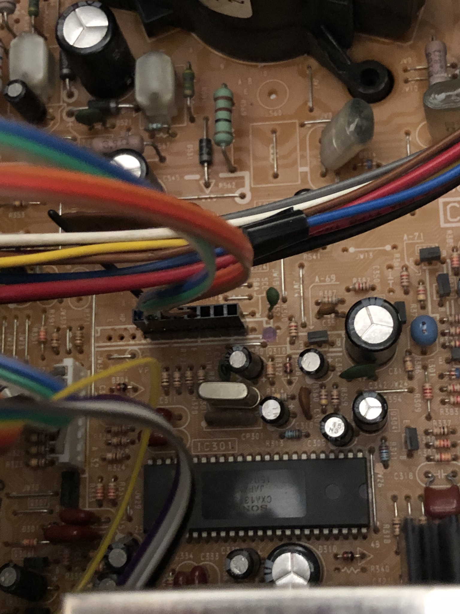
STEP 1: Add a male DuPont connector for RGB
Unlike the 20" counterpart, the KV-20EXR20, the A-31 header and the four 100 ohm resistors that come between it and the jungle chip were already populated. However, the A-31 connector had to be removed and replaced with a male DuPont because the connector's pins were too short to securely seat a DuPont cable.
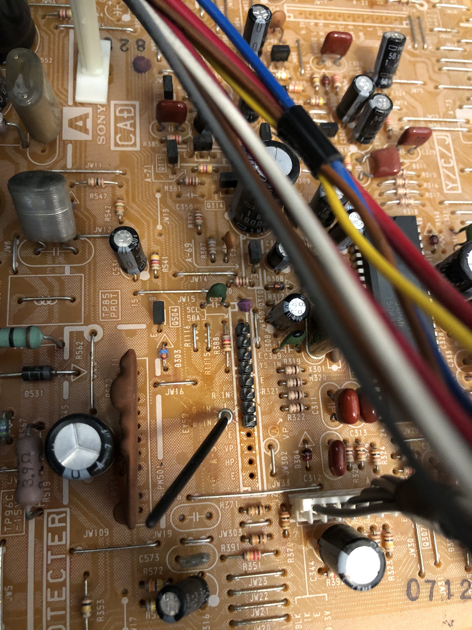
Populate the A-31 header with a 5-pin male DuPont header connector in the pins labeled "B IN", "G IN", "R IN", "E", and "YS".
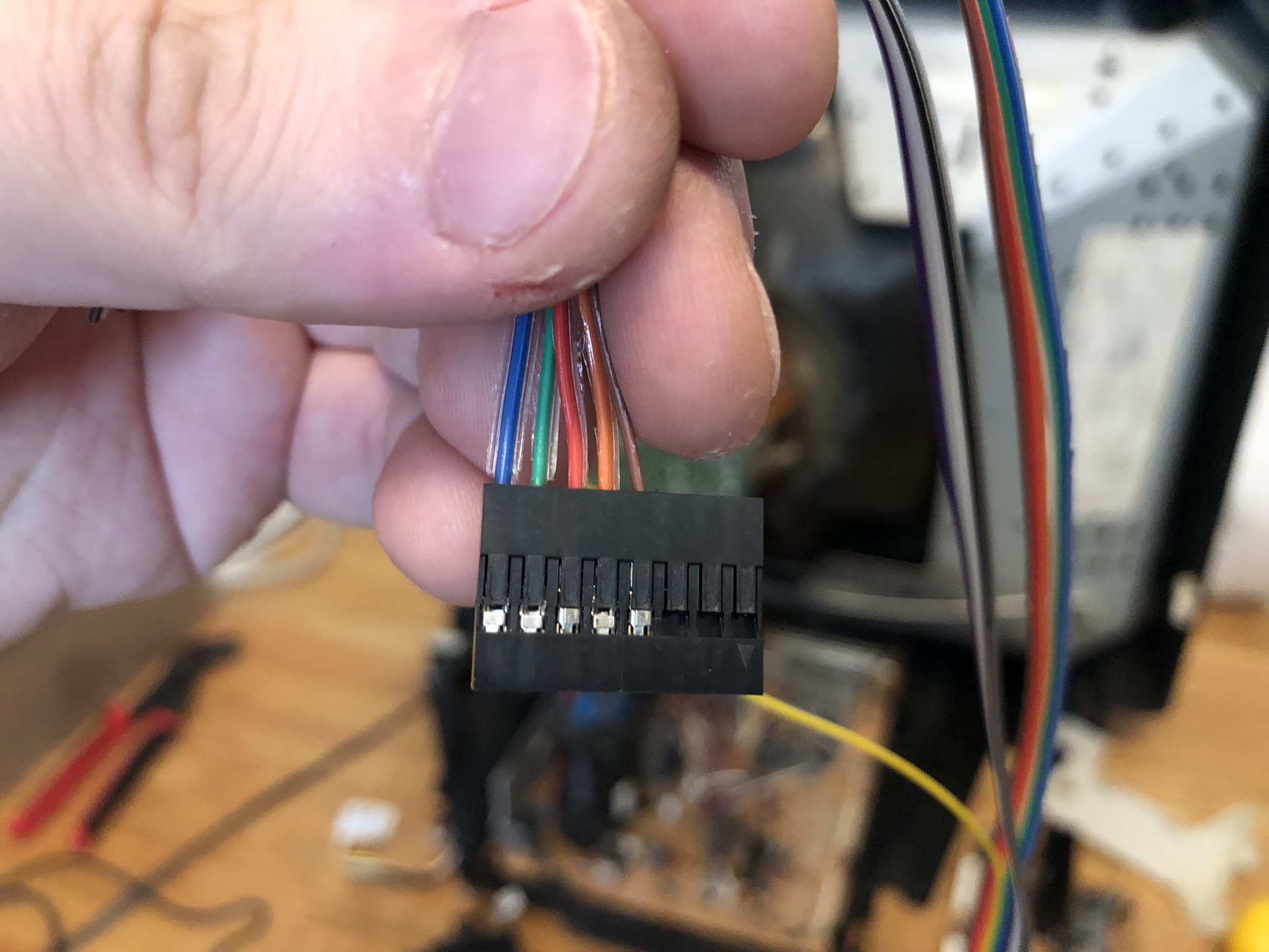
STEP 2: RGB wires for female DuPont connector
Five of the wires from the Mux board IDC cable (Blue, Green, Red, Orange, and Brown) were crimped to a female DuPont connector for connection to the header on the TV chassis.
NOTE
In the new PCB design Orange and Purple wires were reserved as optional and not connected to ground. On the board side, you will need to short them to ground.
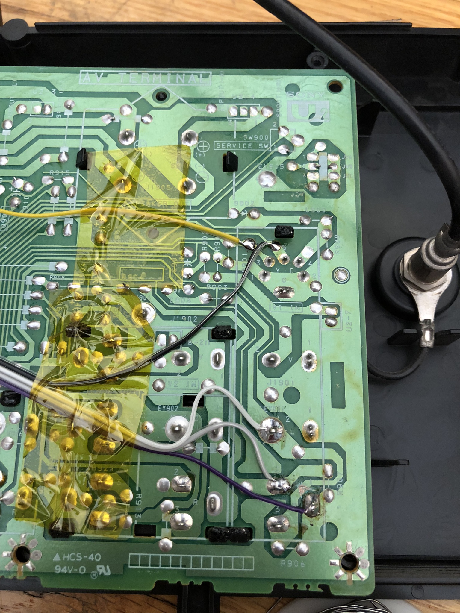
STEP 3: Sync and Audio wires
The black ground wire was connected to the S-Video sensing circuit on the U2 board to allow the use of S-Video Luma as a Sync input.
NOTE
In the new PCB design Orange and Purple wires were reserved as optional and not connected to ground. On the board side, you will need to short them to ground.
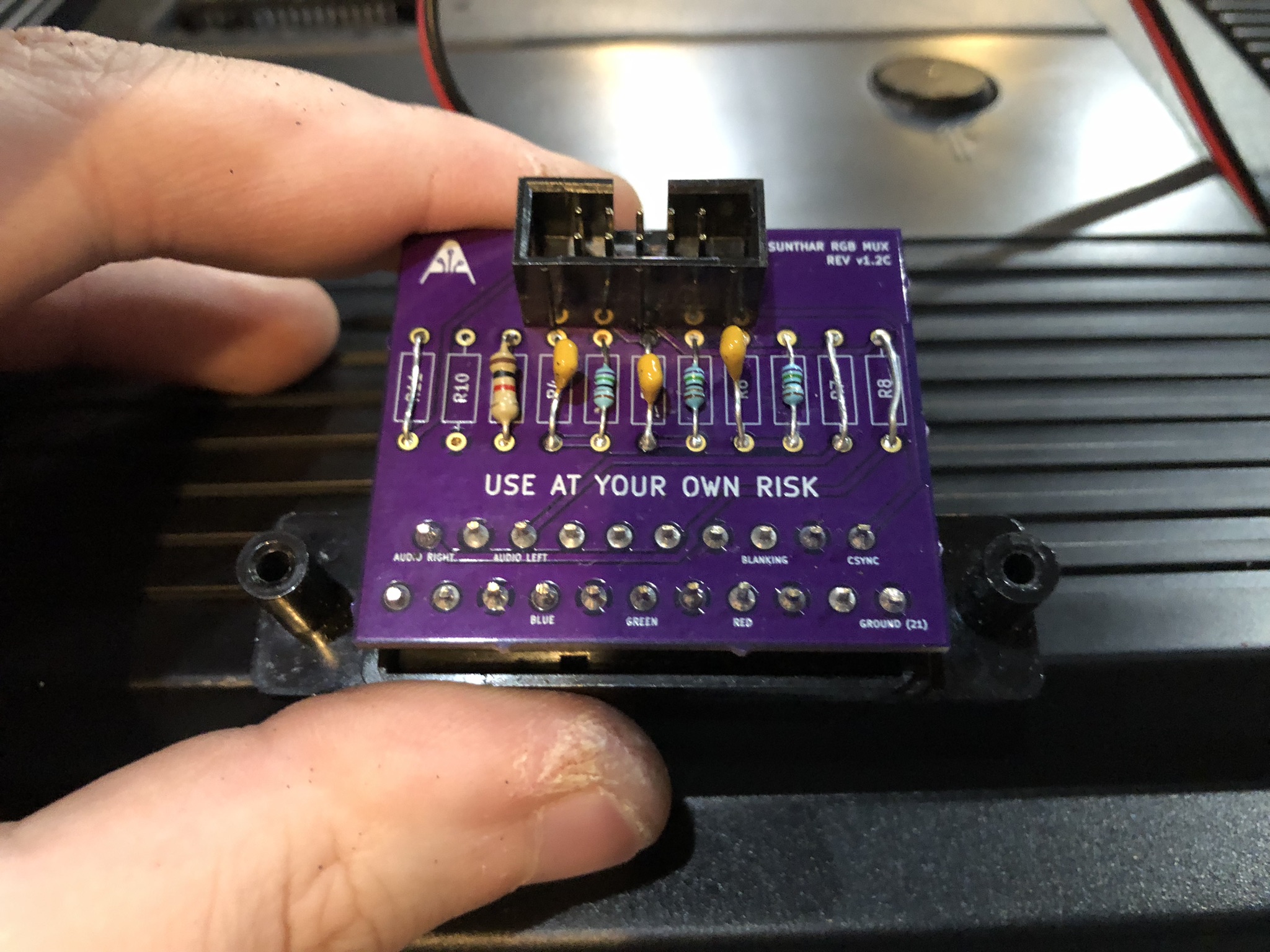
STEP 4: RGB mux board
This mod uses the RGB mux board. This is optional, but will make your mod easier and stable. You can also create the circuit presented in the schematics above without the board. Please also checkout the mux calculator to play with your own values.
| On Sony CRT Chassis | KV-27EXR20 |
|---|---|
| 0.1μF caps replaced | No |
| Add diodes on chassis RGB lines? | No |
| Add blanking diode on chassis | No |
| Replace blanking resistor on chassis | No |
| RGB mux board | KV-27EXR20 |
|---|---|
| Mux board RGB termination (R1, R2, R3) | 75Ω |
| Mux board RGB input capacitors (R4, R5, R6) | 0.1μF |
| Mux board Audio LR (R7, R8) | 1kΩ |
| Mux board blanking diode (R9) | 1N4148 |
| Mux board blanking ground resistor (R10) | open |
| Mux board blanking resistor (R11) | 1kΩ |
| Mux board transistor base resistor (R12) | 1kΩ |
| Mux board transistor (Q1) | PN2222A |
Compatible mux boards:
STEP 5: Service Menu Adjustments
SERVICE MENU
To access the service menu, insert the end of a bent paper clip into a tiny hole on the AV input jack panel and power the set on while holding the paper clip into the button inside the hole for about 10 seconds.
Go into the service menu and adjust the horizontal position (labeled "HPOS" in the service menu) until it looks properly centered. If you're inputting sync into the S-Video input, you should only have to adjust it by about 2 or 3 subtracted from the original value.
STEP 6: Attach the female SCART connector to TV
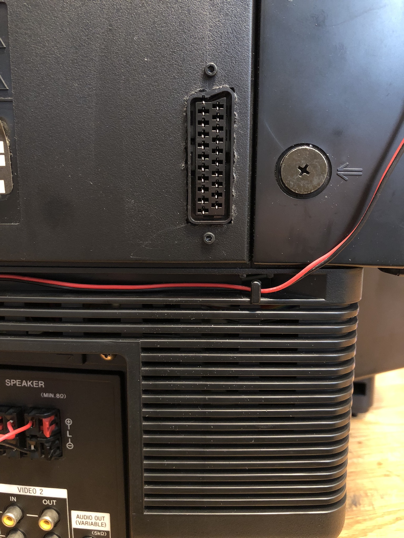
Creating a SCART cutout and mounting it is an art. I have a dedicated section for it.
How to create and mount a SCART female plug?
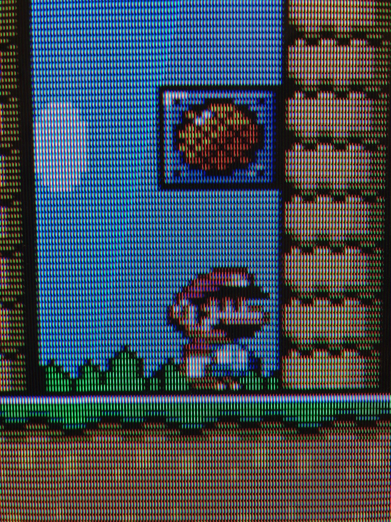
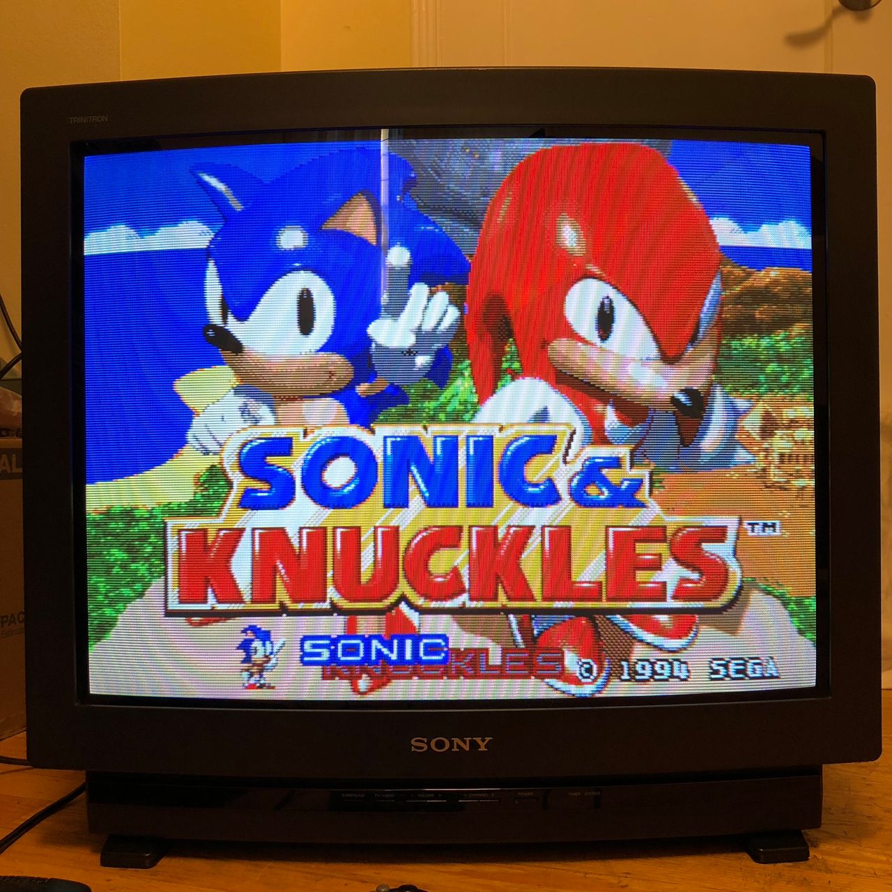
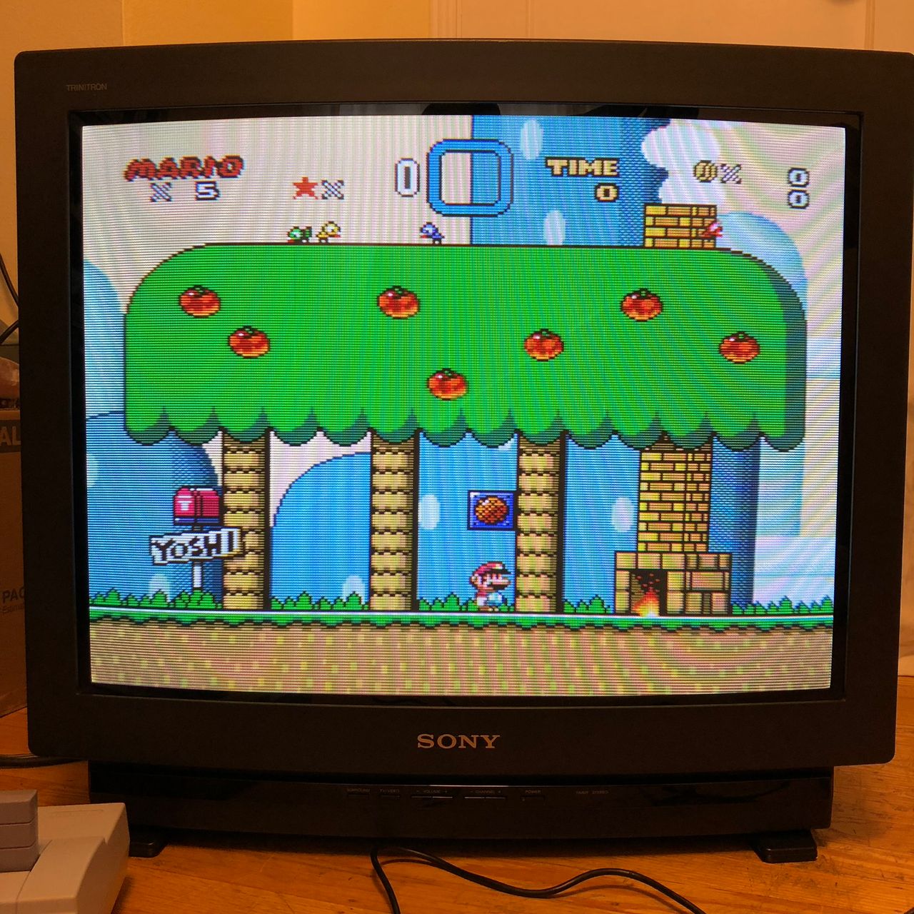
Pictures of the mod
Games
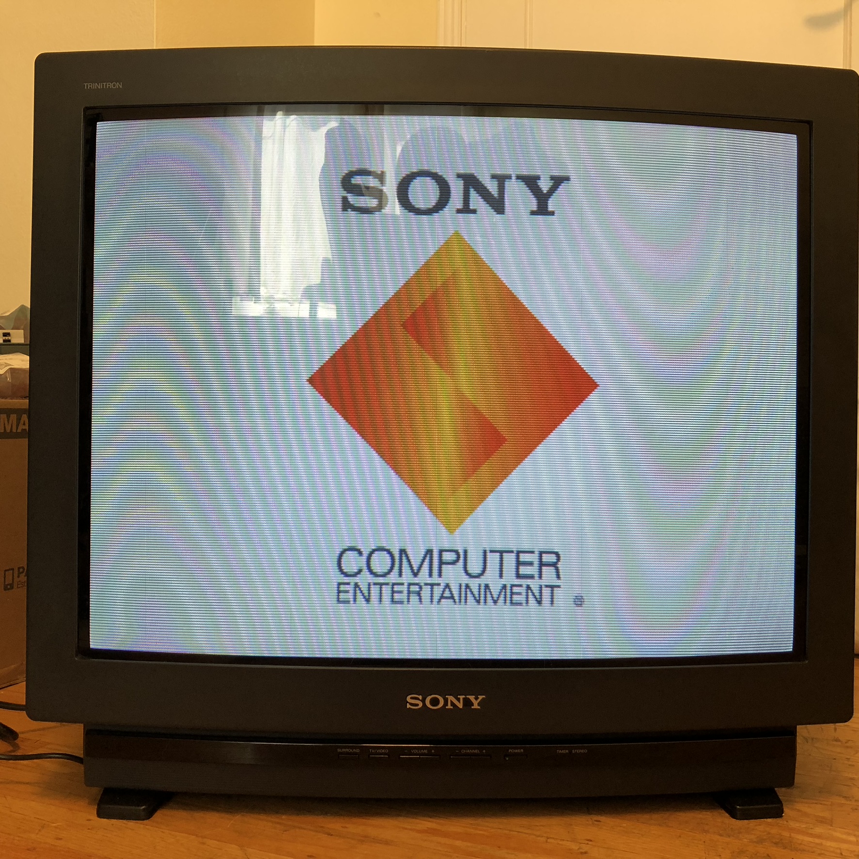
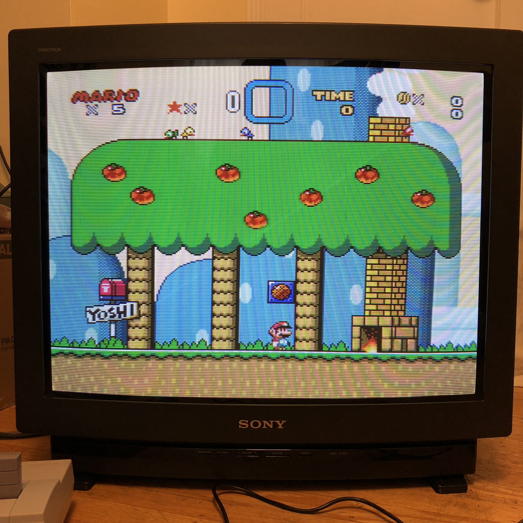
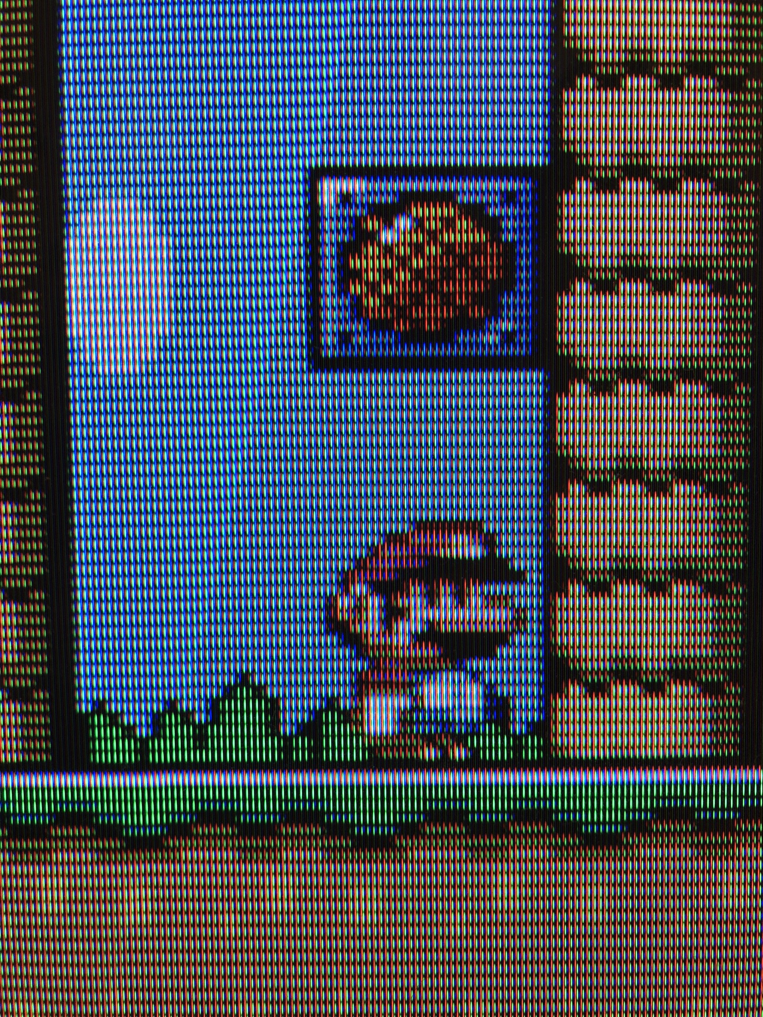
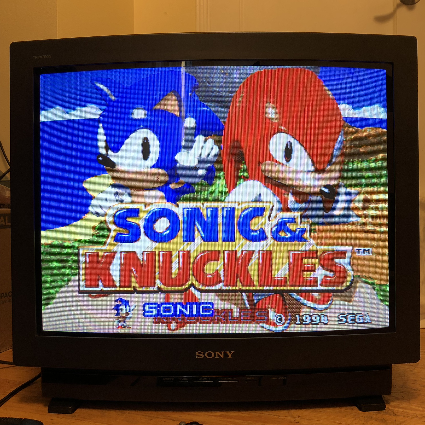
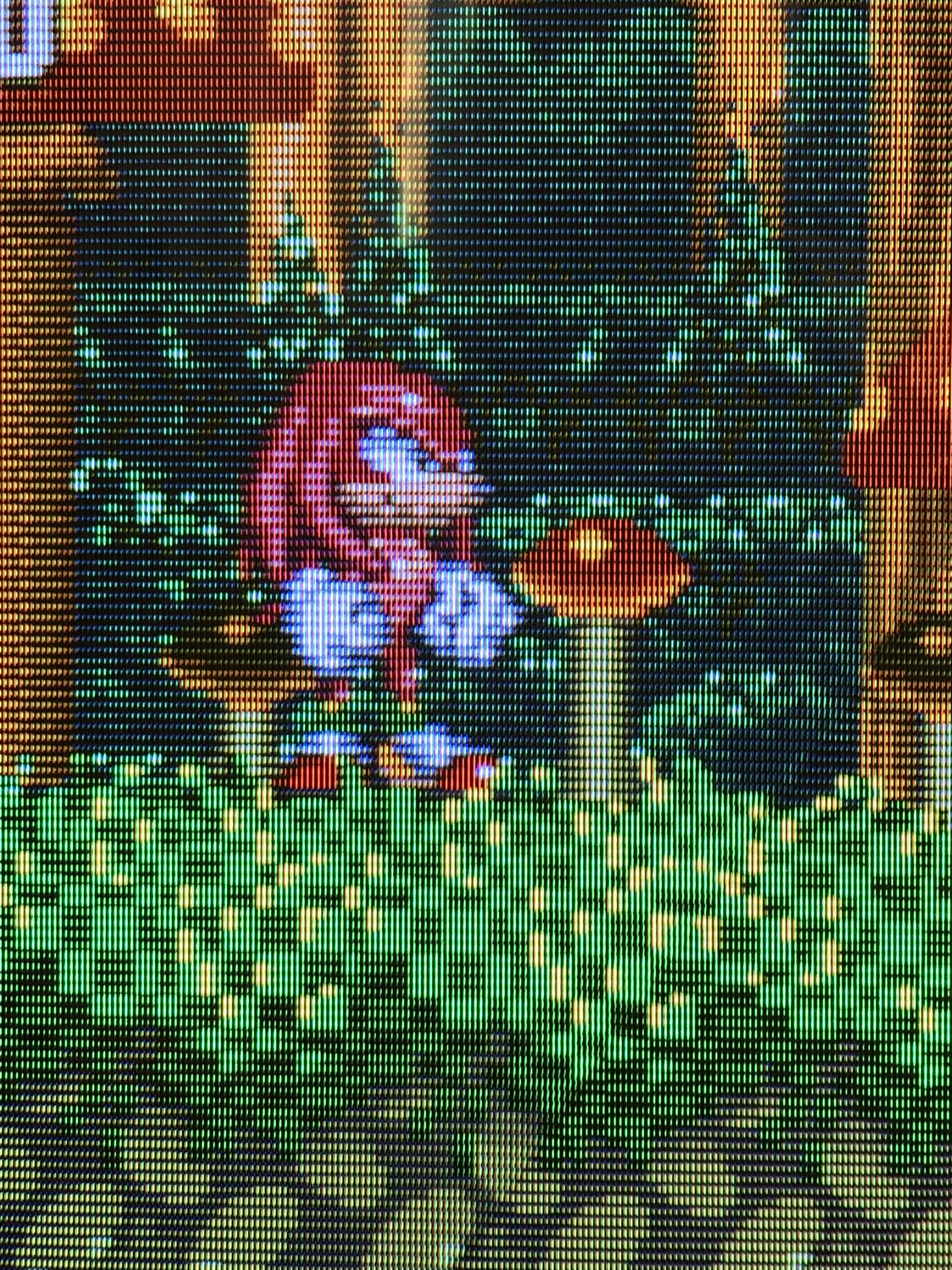
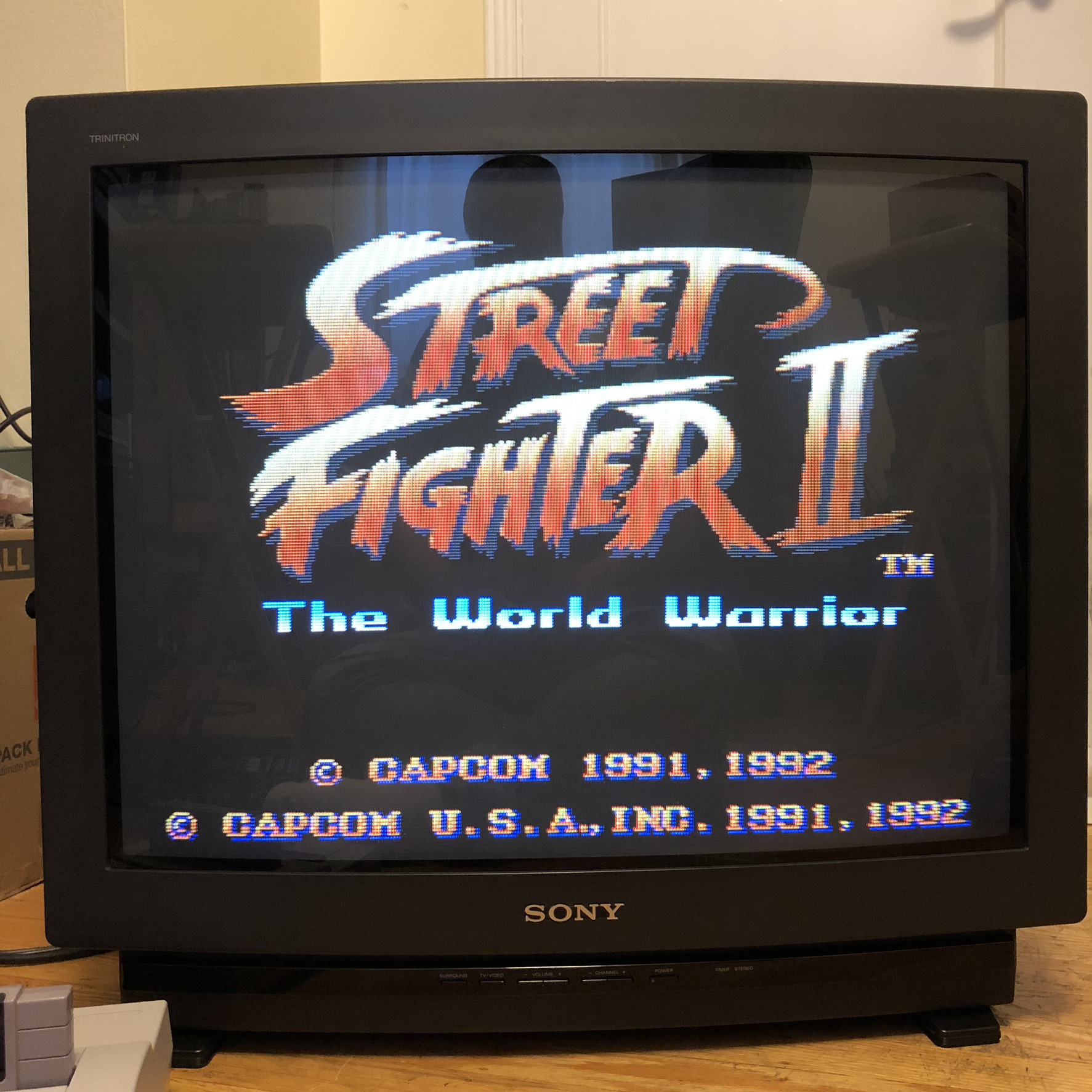
Pictures
Reference Photos