Apex AT1302
Apex AT1302 CRT RGB mod
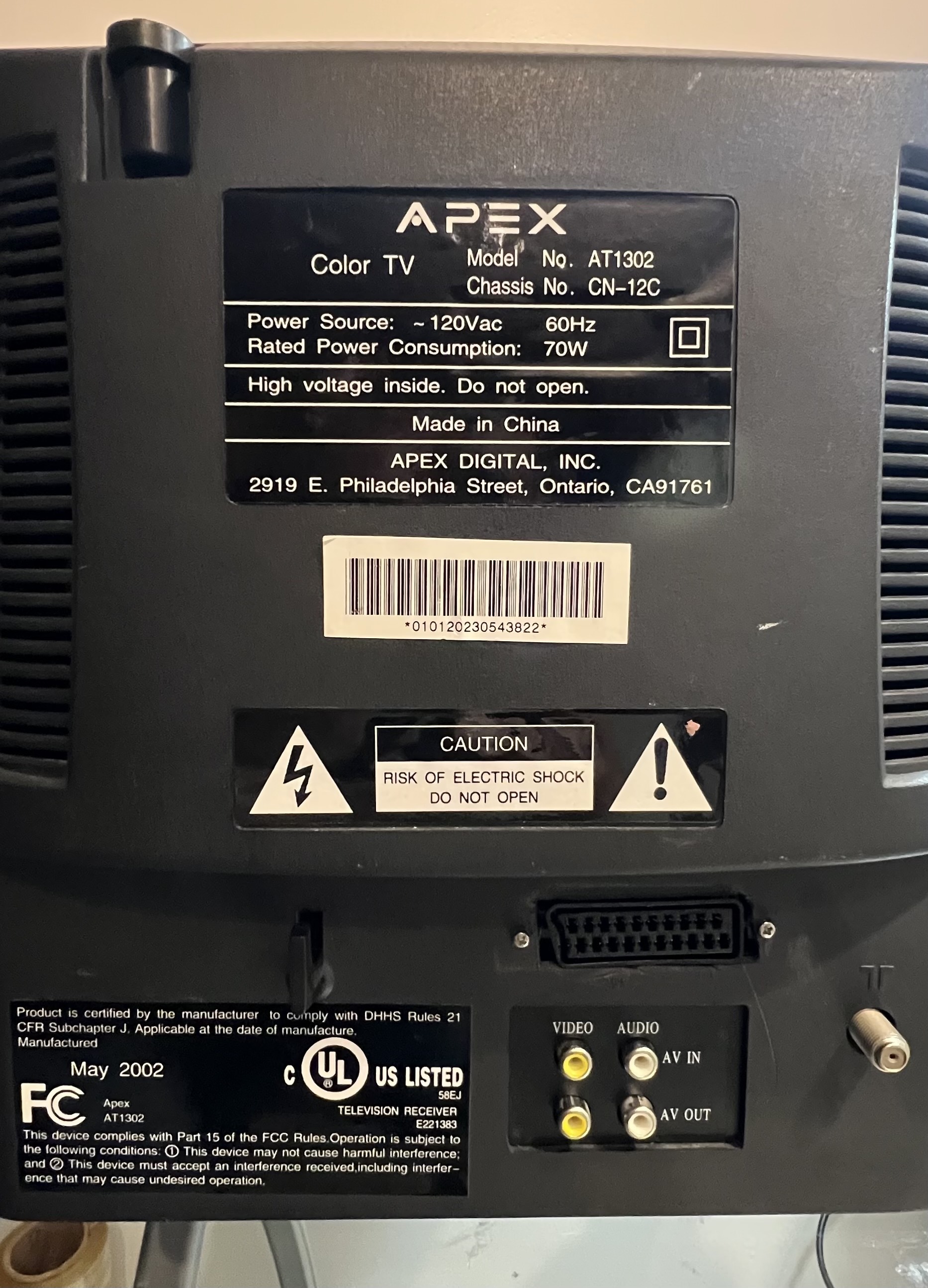
The Apex AT1302 is a 13-inch CRT display launched in 2001.
The CRT is equipped with mono speakers and offers RGB modifiability, allowing enthusiasts to enhance their experience through RGB modification via a mux method.
View full CRT details and more mod examples →
This mod was performed by Enrique Leon.
Contributors
Thank you to everyone who contributed to this guide:
- sky — showcase author
- Matt Ross — contributor, Specs from CRT Database
- Enrique Leon — contributor, RGB mod and pictures
CRT safety
Caution
You can die doing this! So read carefully! CRT TV is not a toy. Do not open a CRT TV. If you don't have any prior knowledge about handling high voltage devices, this guide is not for you. CRT TV contains high enough voltage (20,000+ V) and current to be deadly, even when it is turned off.
Plan of attack
Manuals and Datasheets
Specs
- Year: 2001
- Format: NTSC
- Chassis: CN-12C
- Tube: Irico 37SX110Y22-DC05
- Jungle Chip: Sanyo LA76814
- OSD Chip: CHT0407
- Screen Size: 13"
- Inputs: Composite, RF
Schematics
Get hold of the schematics for your TV. Understand where the RGB and Fast Blanking signals go from OSD to the Jungle (Chroma) chip.
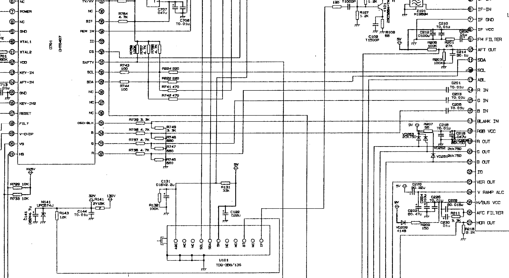
R739 is the blanking in-line resistor. In the schematics it shows as it is 3.3kohms. Blanking ground resistor is also 3.3kohms. This says the blanking voltage is at 2.5V.
RGB mux diagram
Prepare the mux diagram. If you are building your own circuit, this diagram should help.
Performing the mod
STEP 1: Remove the following components
Remove the RGB resistors to ground
- R746
- R747
- R748
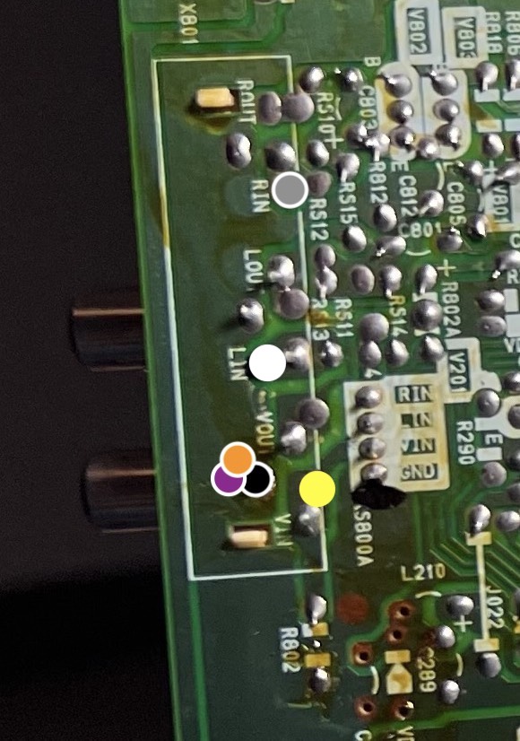
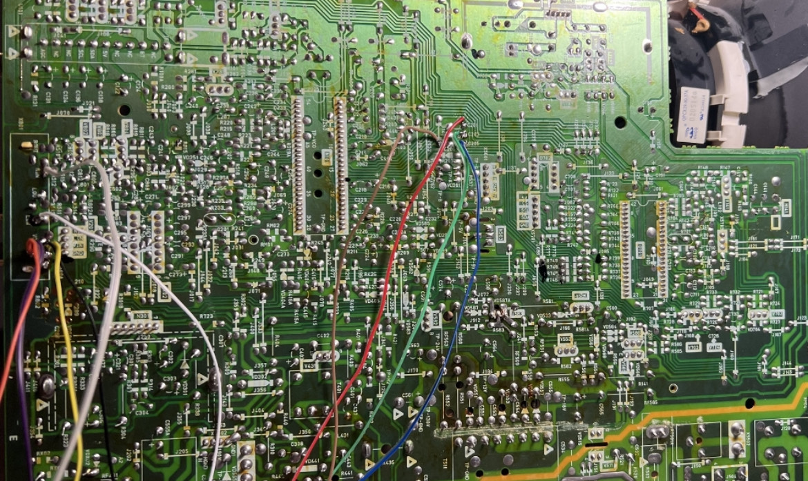
STEP 2: Connect RGBs, Blanking and Audio
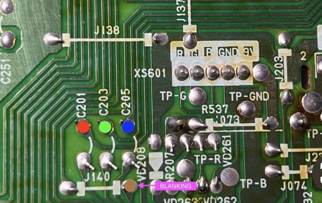
Connect the RED, GREEN, BLUE, BLANKING wires
Connect the SIGNAL, AUDIO RIGHT, AUDIO LEFT, GROUND wires
1.4B or 1.4C kit should work well for this set. You don't need the transistor addon.
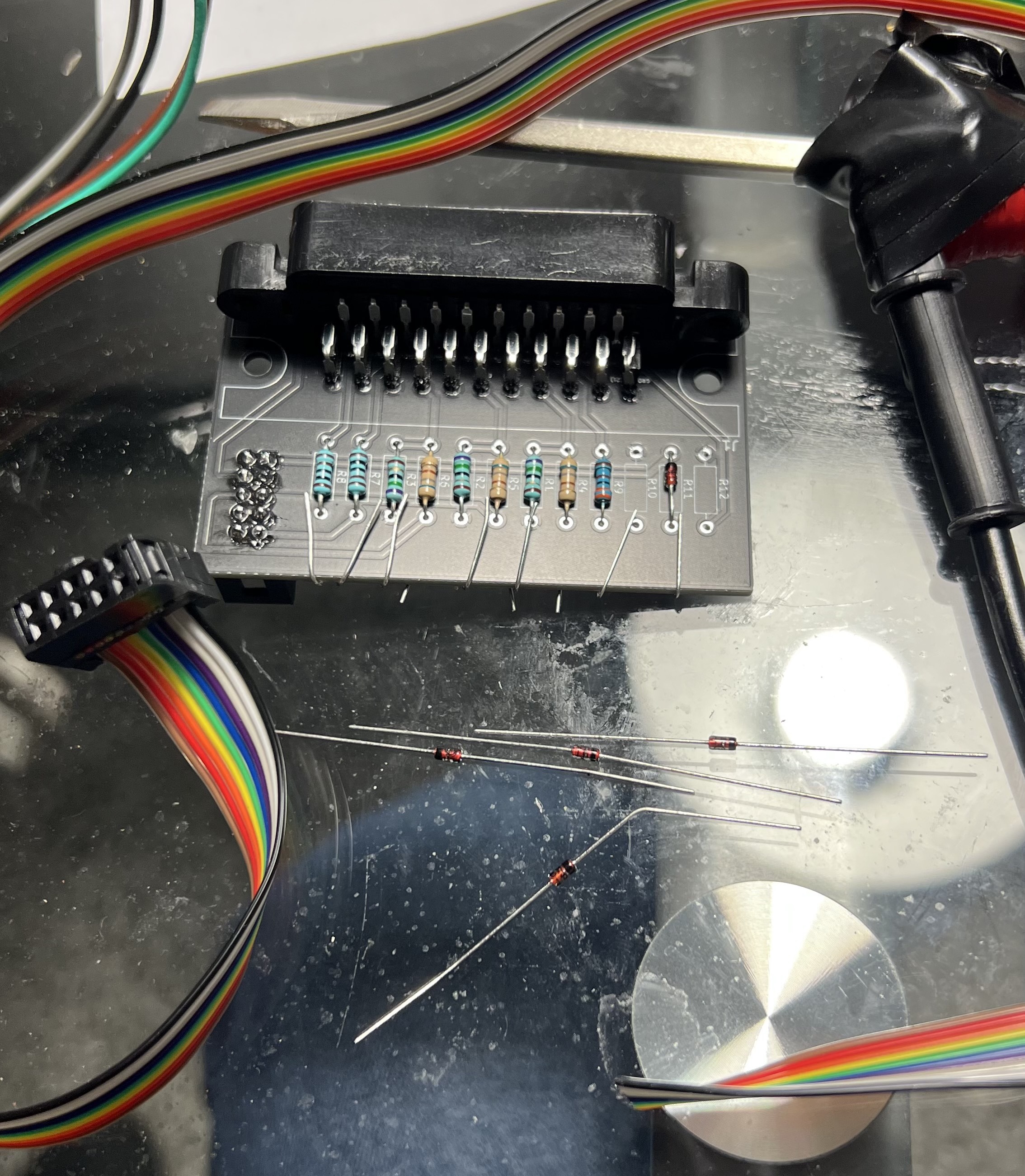
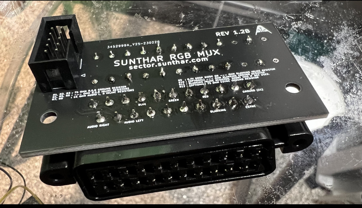
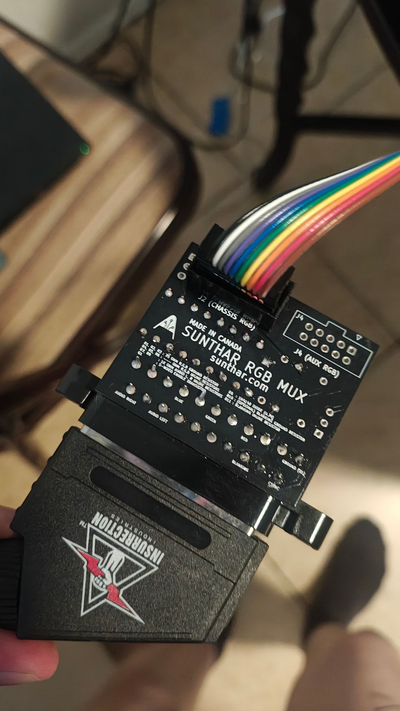
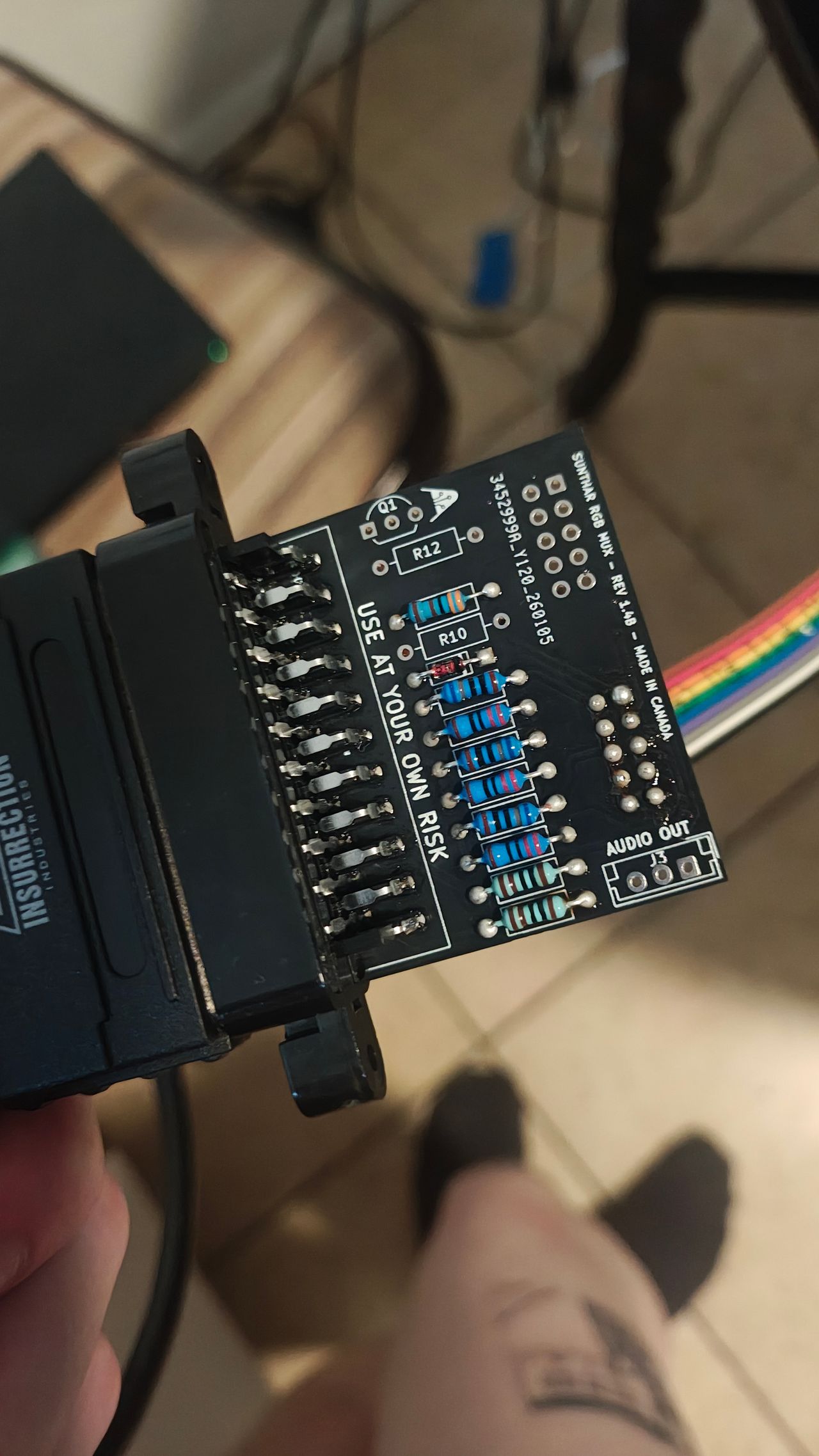
STEP 3: Build your MUX board
This mod uses the RGB mux board. This is optional, but will make your mod easier and stable. You can also create the circuit presented in the schematics above without the board. Please also checkout the mux calculator to play with your own values.
| On Apex CRT Chassis | AT1302 |
|---|---|
| CRT RGB inline resistor | 4.7kΩ |
| CRT RGB ground resistors removed | 680Ω |
| 0.1μF caps replaced | No |
| Add diodes on chassis RGB lines? | No |
| Add blanking diode on chassis | No |
| RGB mux board | AT1302 |
|---|---|
| Mux board RGB termination (R1, R2, R3) | 220Ω |
| Mux board RGB inline resistors (R4, R5, R6) | 680Ω |
| Mux board Audio LR (R7, R8) | 1kΩ |
| Mux board blanking diode (R9) | 1N4148 |
| Mux board blanking ground resistor (R10) | open |
| Mux board blanking resistor (R11) | 3.3kΩ |
Compatible mux boards:
| AT1302 Chassis | AT1302 |
|---|---|
| RGB inline resistros (R736, R737, R738) schematics | 4.7kΩ |
| RGB inline resistros (R736, R737, R738) measured | 3.3kΩ |
| Blanking inline resistor (R739) | 3.3kΩ |
| Blanking ground resistor (R749) | 3.3kΩ |
| RGB ground resistor (R746, R747, R748) | 680Ω |
| RGB inline caps (C201, C203, C205) | 0.01uF |
Please note 220Ω resistor was used for termination to balance contrast and brightness.
STEP 4: Attach the female SCART connector to TV
Creating a SCART cutout and mounting it is an art. I have a dedicated section for it.
How to create and mount a SCART female plug?
Enrique's initial RGB modification was a success. By using a template, drill, and file, it is possible to create a more precise and tidy SCART cutout.
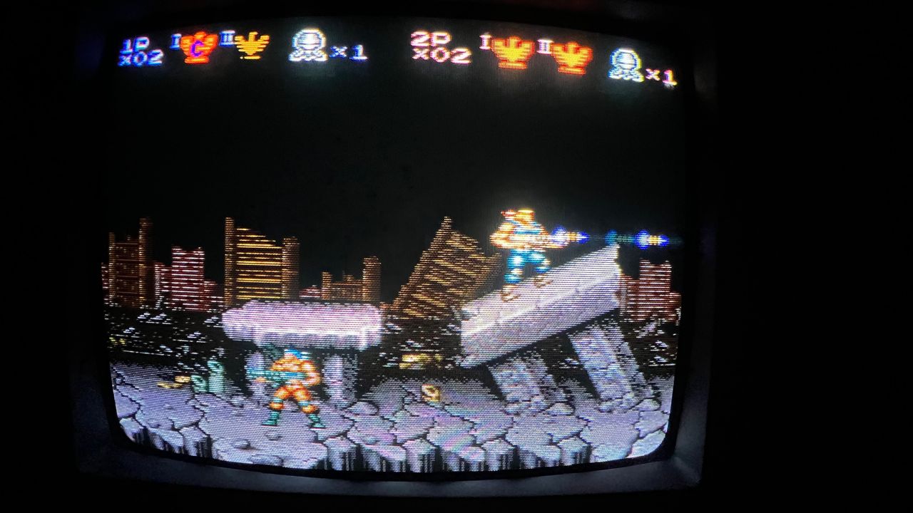
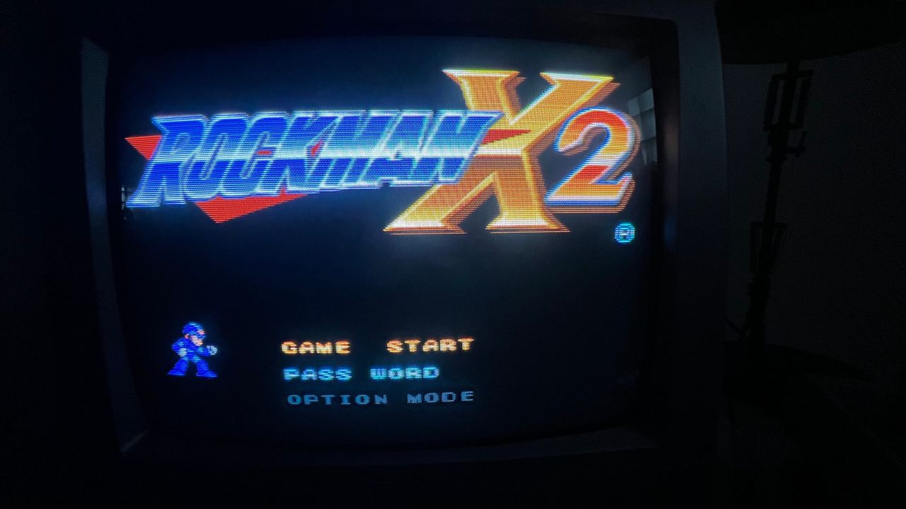
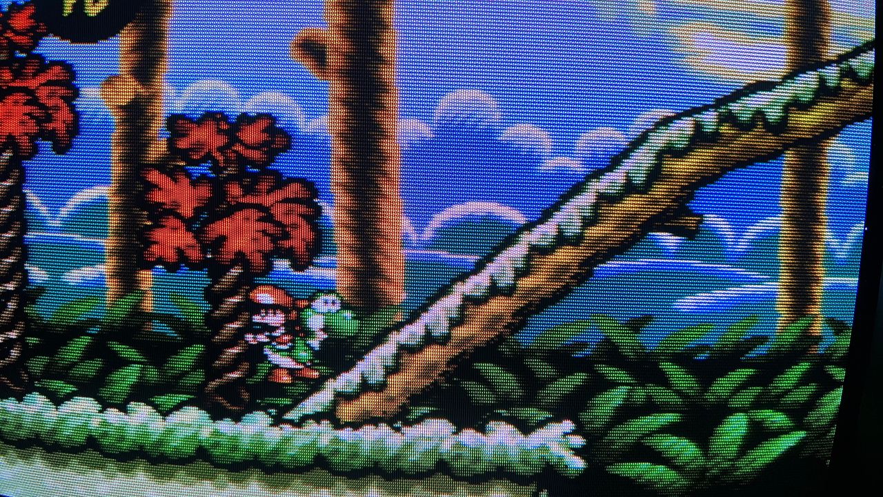
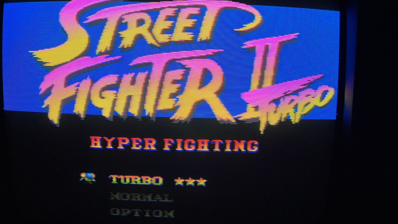
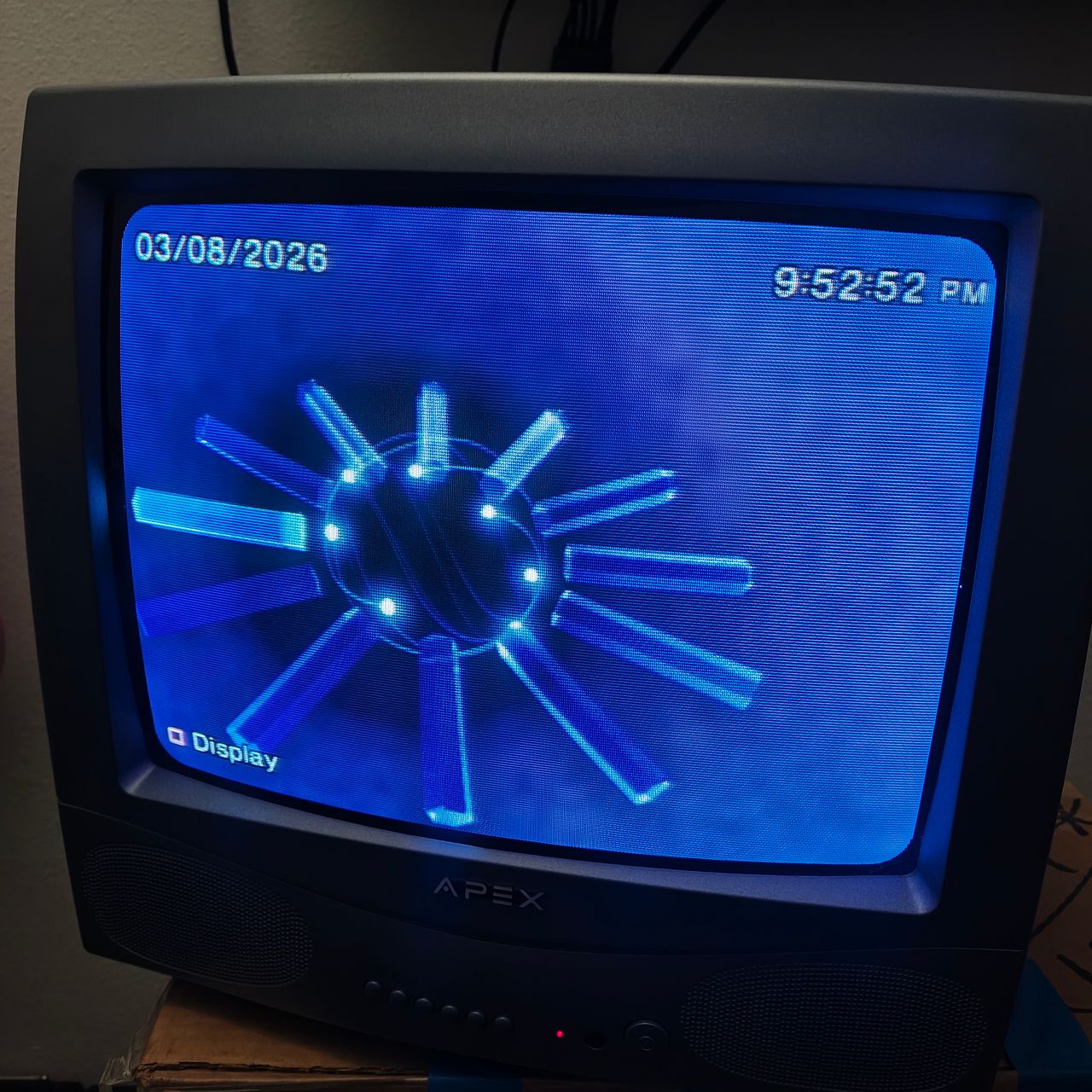
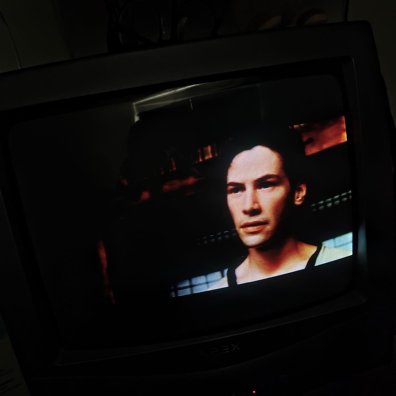
Pictures
Photos by sky
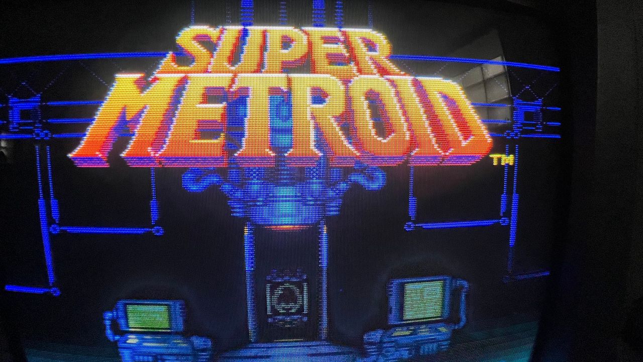
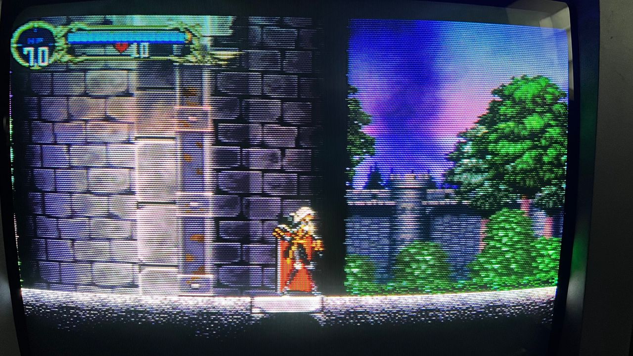
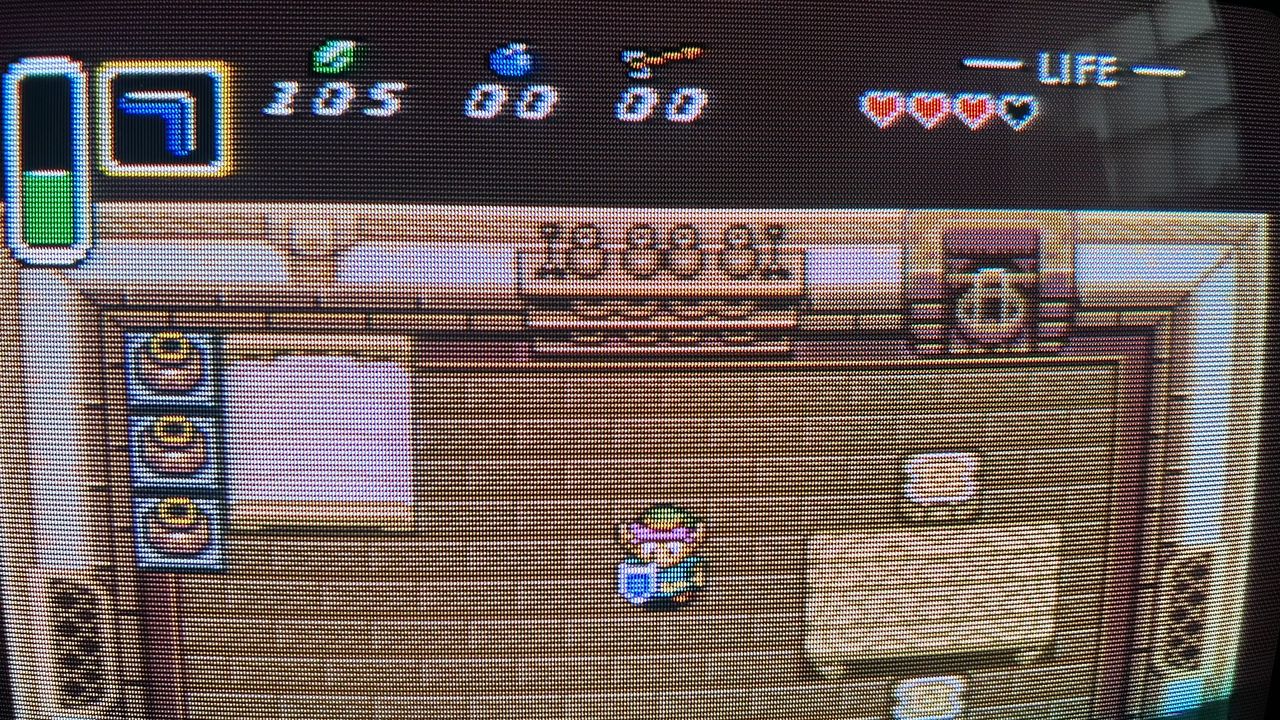
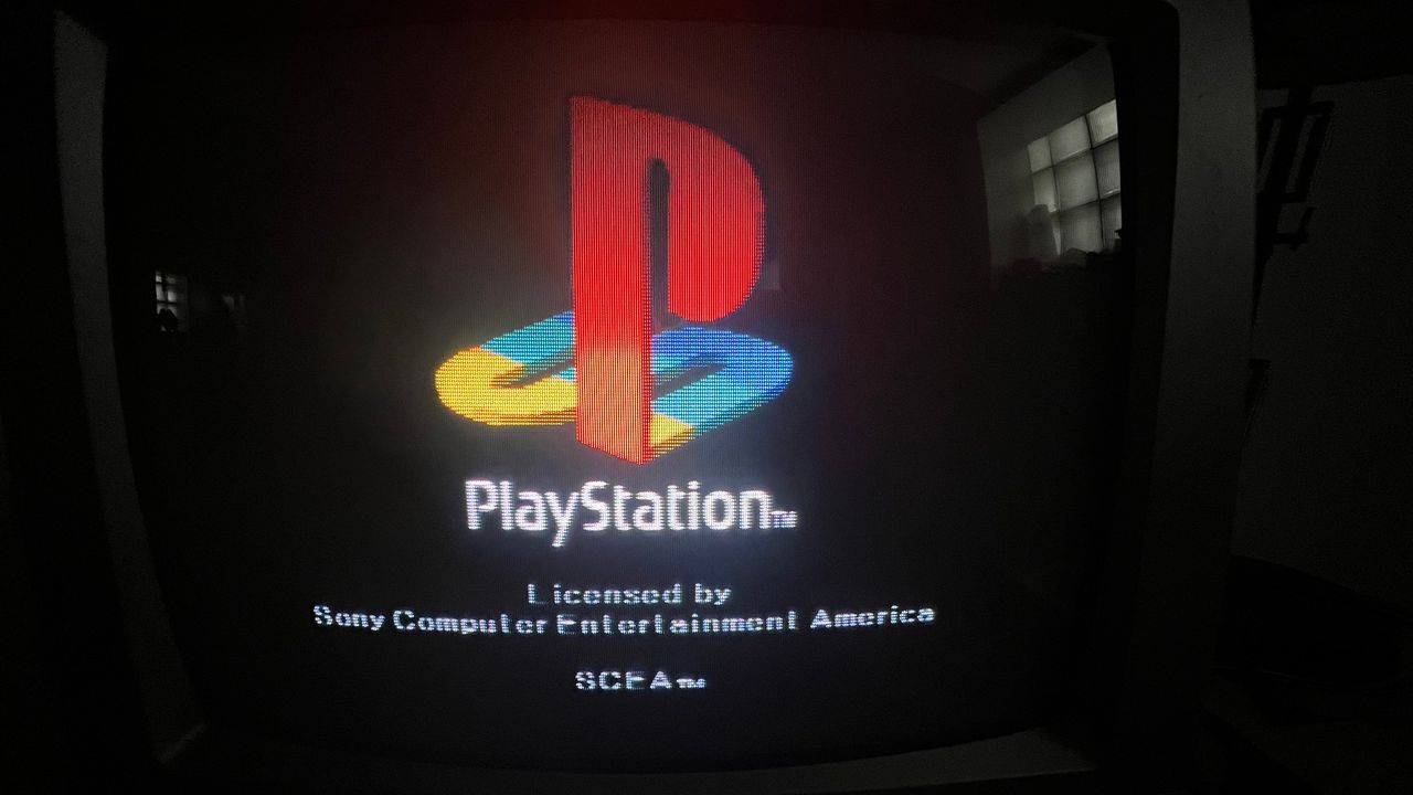
RGB modification showcase converted from a community support request.
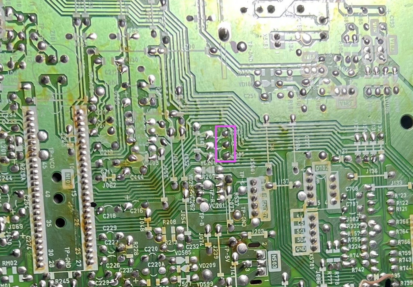
Reference Photos