RGB modding theory
Stay curious
I noticed most CRT RGB mods only show what to do, and don't really talk about how it technically works. If you are curious and want to know a bit more about the science behind this mod, then I want this page to answer that. Once you know how this works, you are not dependent on someone to make a breakthrough. I have tried to simplify it, so that I understand it. I only know a little about this area. Therefore, if there are any corrections or additions that you think might be useful, please do let me know, so that I can update this page.
- CRT = Cathode Ray Tube
- RGB = Red, Green, Blue, Sync (RGBs)
- SCART = Connector used to transmit RGB signals
Here is an article that you might want to read for further background. RGB Introduction by RetroRGB
Video signals - worst to the best
- RF
- Composite
- S-Video
- Component
- RGB
Note: some may argue there is no difference between Component vs RGB. While it is not noticeable on a consumer grade CRT, there is a slight difference. Most CRTs have to process component signals to RGB. This process is not totally lossless. Let's not get hung up on this, because modding a TV to have RGB input has other benefits.
RGB modding primarily benefits CRTs that only have composite or s-video inputs. It also benefits CRTs with component input, so that you have an additional input option. Why just have one input, when you can have both? Another benefit is you have several options when it comes to selecting a video cable. Component cables are too expensive? No problem!
Analog signals
If I can't shoot on film I'll stop making movies
Quentin Tarantino
Analog signals are like continuous waves, capturing all the details. It also gracefully degrades over time. That is what makes them more exciting. While the science of analog signals are a bit complicated, it is easily noticeable by humans who are used to watching and listening to` analog content for the past few decades. This is why audio enthusiasts prefer listening to vinyl (even with some of that cracking/popping noises). While most industries have moved to digital for its higher resolution, ease of use and compatibility, analog will still remain interesting for decades.
For retro gamers, lag can be pretty annoying. But, what does lag have anything to do with the analog signals? Older SD CRT technology works mostly based on analog signals. It takes the R, G, B signals, amplifies and beams it using an electron gun. The illuminated phosphors in front of the CRT tube then displays the image. Because there is little to no processing needed, there is minimal render delay compared to the LCD, LED technology you see in the market today. Speed of electrons is the fastest known in the universe. Using that to render images on a tube is simply fascinating. "The Slow Mo Guys" did a capture at 380,000 frames per second (yes three.hundred.and.eighty.thousand) with a CRT to show how fast the signal is rendered on a CRT. It is absolutely fast! YouTube Link
Various tests show LCD/LED technology is closing the response gap against CRT. I really don't want to get into that debate now. CRT is a very different technology and it will remain nostalgic for those who grew up with it for decades to come.
OSD and chroma chips (IC, microchip)
For CRT TVs that are RGB moddable, there are two chips that are involved.
- OSD chip (On Screen Display)
- Chroma/Jungle chip (main video processor)
OSD chip shows the menu, volume, channel, video input etc. on top of the video signal. It is accomplished by muxing (Muxing = mixing) the OSD with the video input signal that is performed within the chroma chip.
Tips
Newer CRTS have these two chips integrated into a single chip. Therefore, please remember not all CRT TVs are RGB moddable.
Genius of muxing external RGB signals with OSD RGB signals
A signal needs to be sent to the chroma chip, so that it knows it should mux OSD and show it on the screen. Without it, you wouldn't see the volume bar on the screen. When you press the Vol+ button on your remote a 5V signal is sent to the chroma chip. This signal is typically called blanking/fast blanking signal. When this blanking signal is received by the chroma chip it displays the video signal produced by the OSD chip. This is how you see the volume bar.
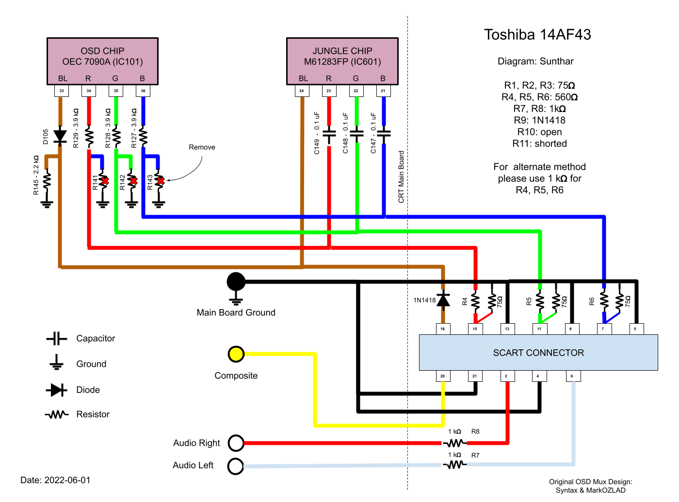
Someone discovered (not sure who) the ability to intercept and inject the external RGB signals into this internal RGB line. Originally a switch was used to switch between composite/component and RGB. However, later a MUX based model was discovered (by MarkOZLAD, Syntax) to make this work without a switch. It also gave the benefit of being able to see the OSD along with the RGB signal. OSD overlay on these screens is probably not the best, but it does the job! This makes it easier to adjust the geometry or other settings using the service menu.
There is a shmups forum dedicated to several RGB mod experiments that were performed by many CRT enthusiasts.
Peak-to-peak voltage on RGB signals
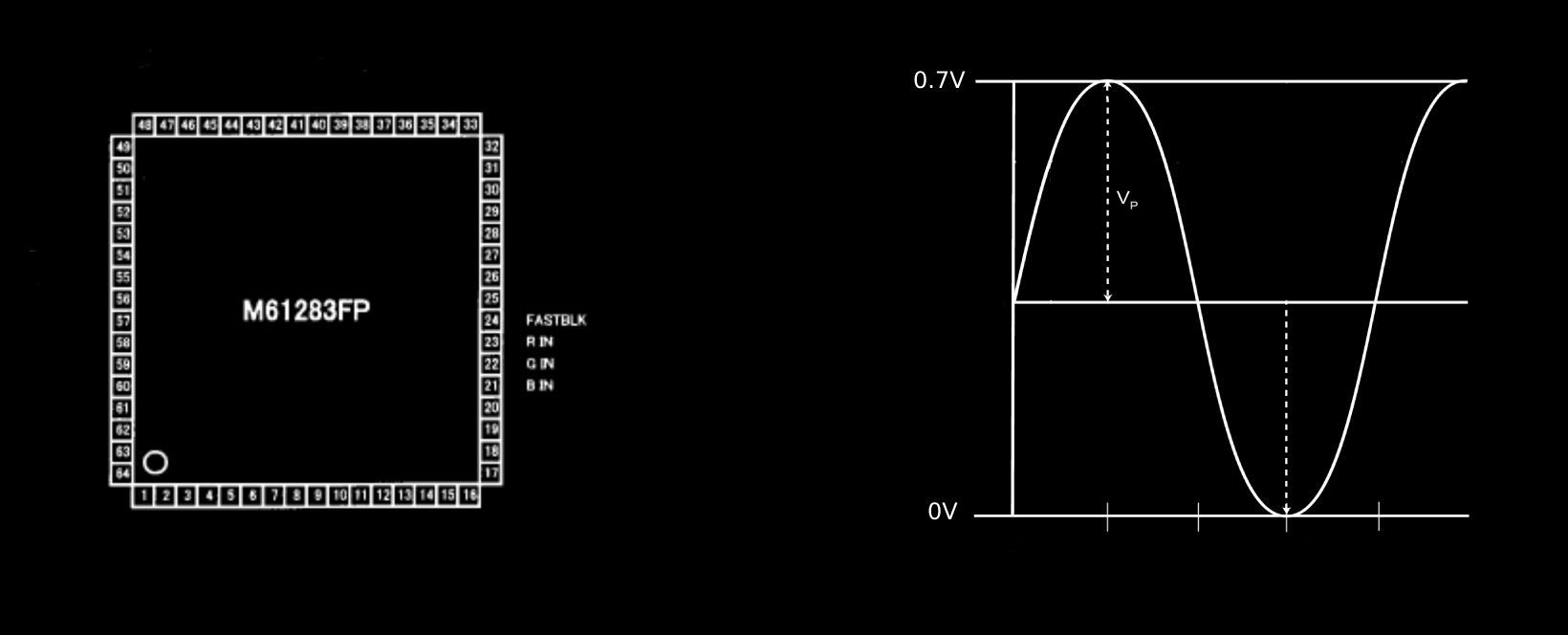
Chroma chip datasheet would explain the maximum allowable peak voltage for the R, G, B signals. In the case of Toshiba (M61283FP), the limit is 0.7V. The same 0.7 peak voltage limit applies to Samsung TXD1973 and several other CRTs. There are some CRTs that have a 0.5 peak voltage requirement. All chips will have some tolerance beyond the peak, but exceeding the peak voltage spec is not advisable and can damage the chroma chip.
Why does this peak-to-peak voltage matter?
When we are modding the TV, and adding the R, G, B signals to mux with the OSD line, we have to make sure this peak voltage spec is respected. OSD generates a 5V signal and the stock circuit on the TV board divides this voltage to match what the chroma chip is expecting.
Blanking voltage
Voltage should be applied to the "Blanking" or "Fast Blanking" pin on the chroma chip so that RGB signals are displayed on the CRT. This signal basically tells the CRT to display what's coming through the analog RGB pins. Based on the chroma chip (differs by CRT, sometimes even within the same model), different voltages will need to be applied. If the correct voltage is not applied, you might not see the RGB video signal, or see the RGB video signal only through the OSD text.
Example: Samsung TXD1943
I think the best way to demonstrate this is through an example. Here we will look at the two important things that matter.
- Finding the external RGB inline resistor value
- Finding the blanking voltage that will help show the RGB video signal
Finding the external RGB inline resistor value
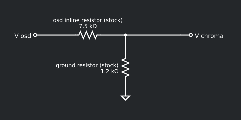
Taking Samsung as an example, we can see how this simple voltage dividing circuit works. If we consider 5V peak voltage to come from the OSD red output, then the stock voltage divider on the main board ensures the voltage going to the chroma (jungle) chip's red input doesn't exceed 0.7 peak voltage.

We need to respect this spec when we mux the signal. If there is a diode present, then the voltage drop across the diode should also be subtracted. In the Samsung example above there are no didoes present.
Continuing with the Samsung example, if we want to inject external RGB signals, we have to add 75 Ohm terminating resistors. The below diagram shows typically what needs to change on the circuit to inject an external R, G, B signal. Showing the circuit diagram just for the Red signal. Samsung CRT in this example doesn't have an inline diode, but showing it in the diagram as a general pattern.
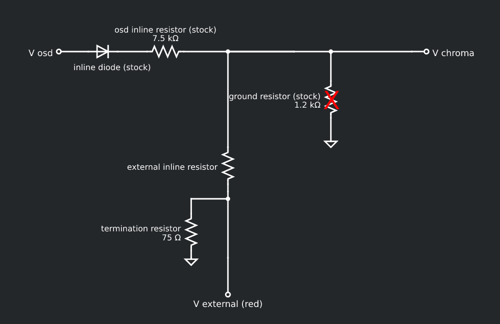
Below formula calculates the peak voltage (V chroma) seen on the chroma chip's R, G, B input

Rearranging this formula, we can calculate the value of the external resistor that is needed on the RGB line to maintain the same peak voltage level. Typically this resistance value is closer to the grounding resistor removed from the board.

For Samsung TXD1973, we can now calculate the value of the external RGB inline resistor using the above formula.

Pre-calculated RGB inline resistor values
Mark C (MarkOZLAD) created this chart on shmups, which can be used for reference.
0.7V p-p with 5V RGB from micom chip 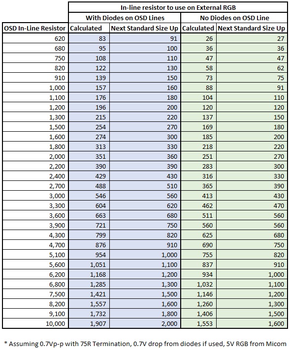
0.5V p-p with 5V RGB from micom chip 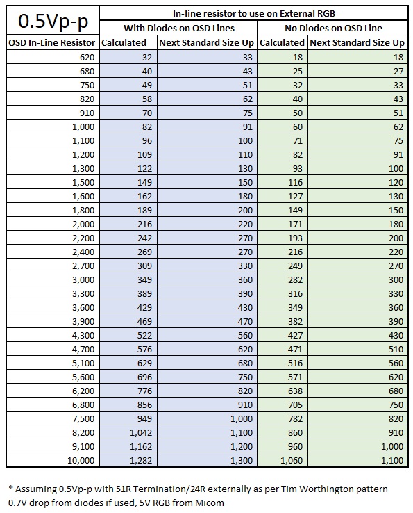
Finding the voltage that should be supplied to the blanking signal
First step here is to find out what voltage goes to the chroma chip to enable blanking for OSD. We can simply calculate using our voltage divider formula. Blanking lines do not have the 0.1uF coupling capacitors that are seen on the RGB lines.
In the case of Samsung TXD1873 we can use the below formula to calculate the voltage on the blanking pin 14 (Vblanking). You will notice the resistor values used are slightly different from the RGB lines. Here we are using 8.2 Kohm inline resistor and 4.7 Kohm grounding resistor to divide the voltage. The resultant voltage is 1.82V
![]()
1.82V is the voltage we need to enable blanking. Our external blanking circuit should comply with this to show a picture on the screen.
Why does the RGB signals go through 0.1uF capacitors?
To filter out the DC noise. These should not be removed.