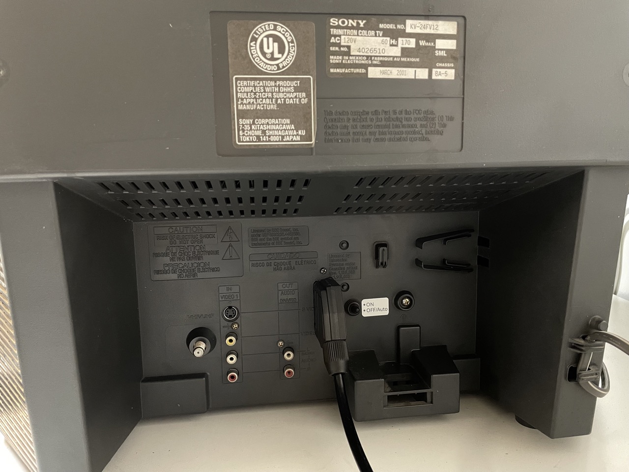
Sony (BA-5) KV-24FV12
Sony (BA-5) KV-24FV12 CRT RGB mod
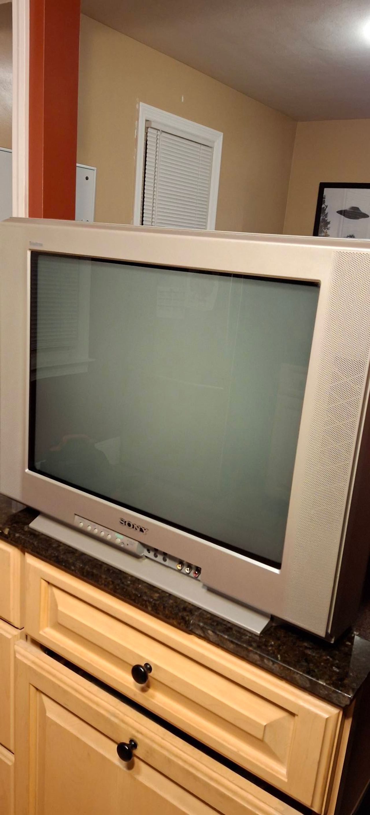
The Sony KV-24FV12 is a 24" FD Trinitron Wega television recognized for its flat screen, high-quality 480i picture, and excellent audio, making it a popular choice for retro gaming. It features a BA-5 chassis and offers S-Video connectivity, but lacks native component inputs, although it can be RGB modded.
View full CRT details and more mod examples →
This tutorial should also cover the RGB mod for the below models with the BA-5 chassis. However, there might be slight differences.
- KV-20FS12
- KV-20FV12
- KV-24FV12
- KV-21FE12
- KV-21FM12
- KV-27FS13
- KV-27FS17
- KV-27FV17
- KV-29FV17
- KV-32FS13
- KV-32FS17
- KV-34FS17
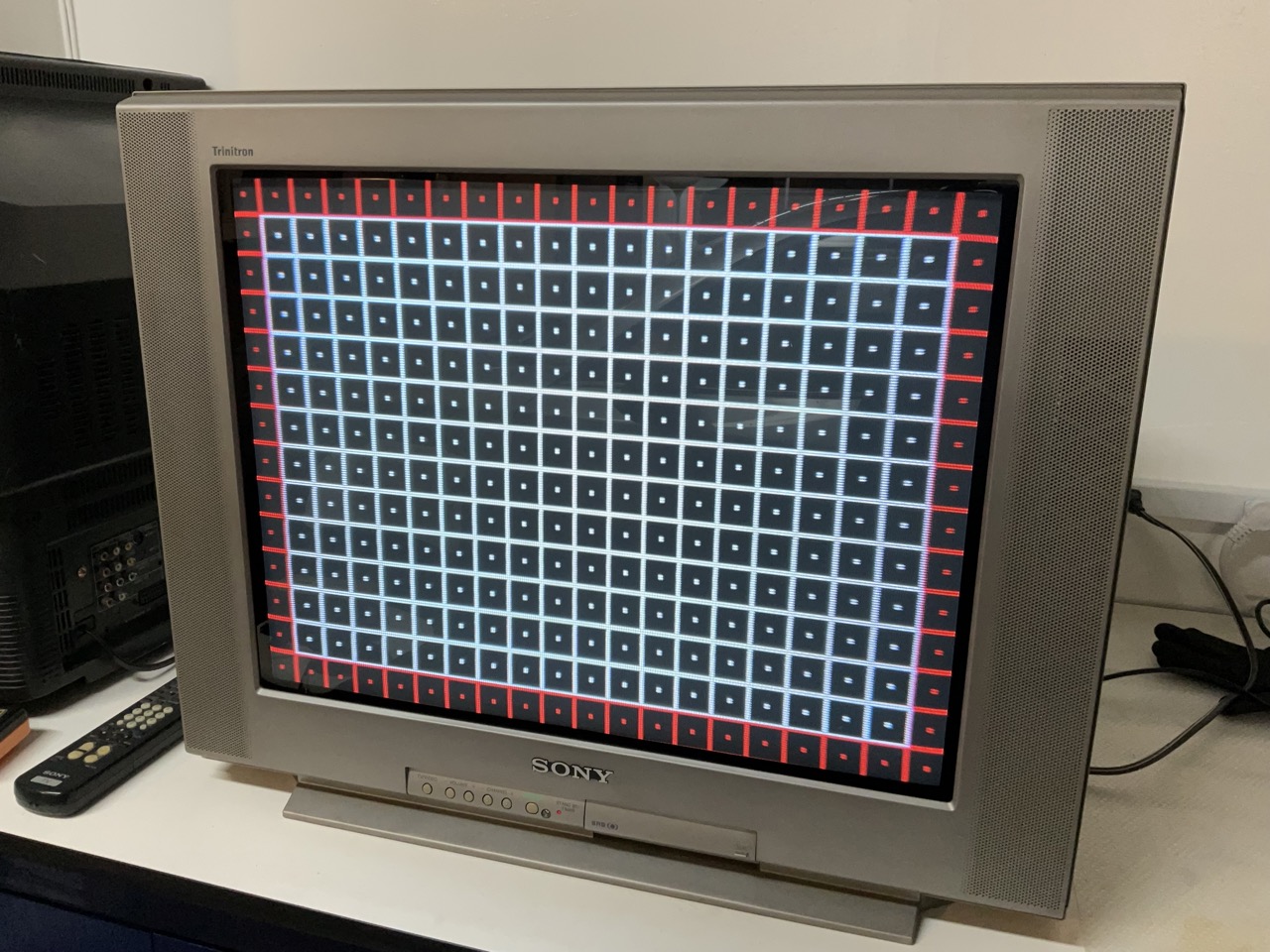
Table of Contents
Contributors
Thank you to everyone who contributed to this guide:
- Sunthar — showcase author
- Matt Ross — contributor, CRT specs from CRT Database.
- tubegaming — author, Pictures
CRT safety
Caution
You can die doing this! So read carefully! CRT TV is not a toy. Do not open a CRT TV. If you don't have any prior knowledge about handling high voltage devices, this guide is not for you. CRT TV contains high enough voltage (20,000+ V) and current to be deadly, even when it is turned off.
Plan of attack
Manuals and Datasheets
Specs
- Manufactured: Mexico (2000, 2001)
- Format: NTSC
- Chassis: BA-5
- Tube: Sony Trinitron A60LPN70X
- Jungle Chip: Sony CXA2131AS
- OSD Chip: M37273MF-258SP
- Screen Size: 24"
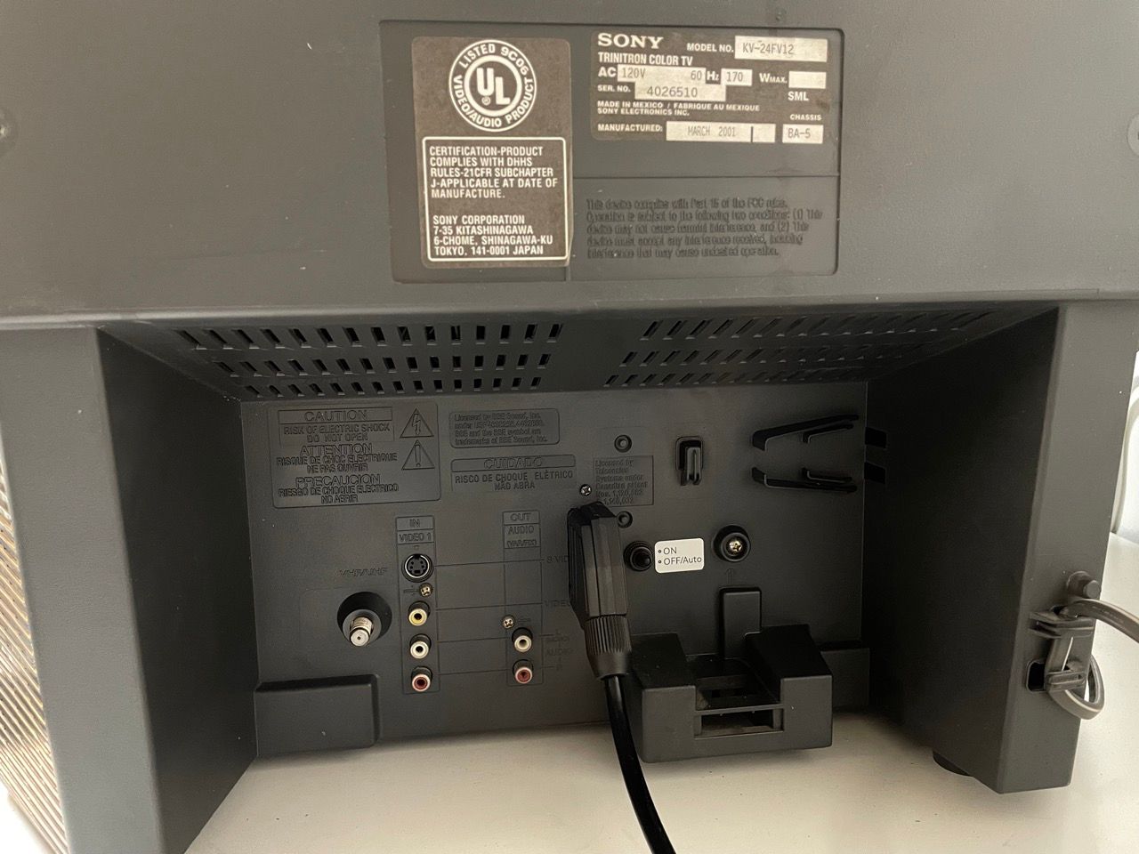
- Inputs: Composite, S-Video, RF
RGB mux diagram
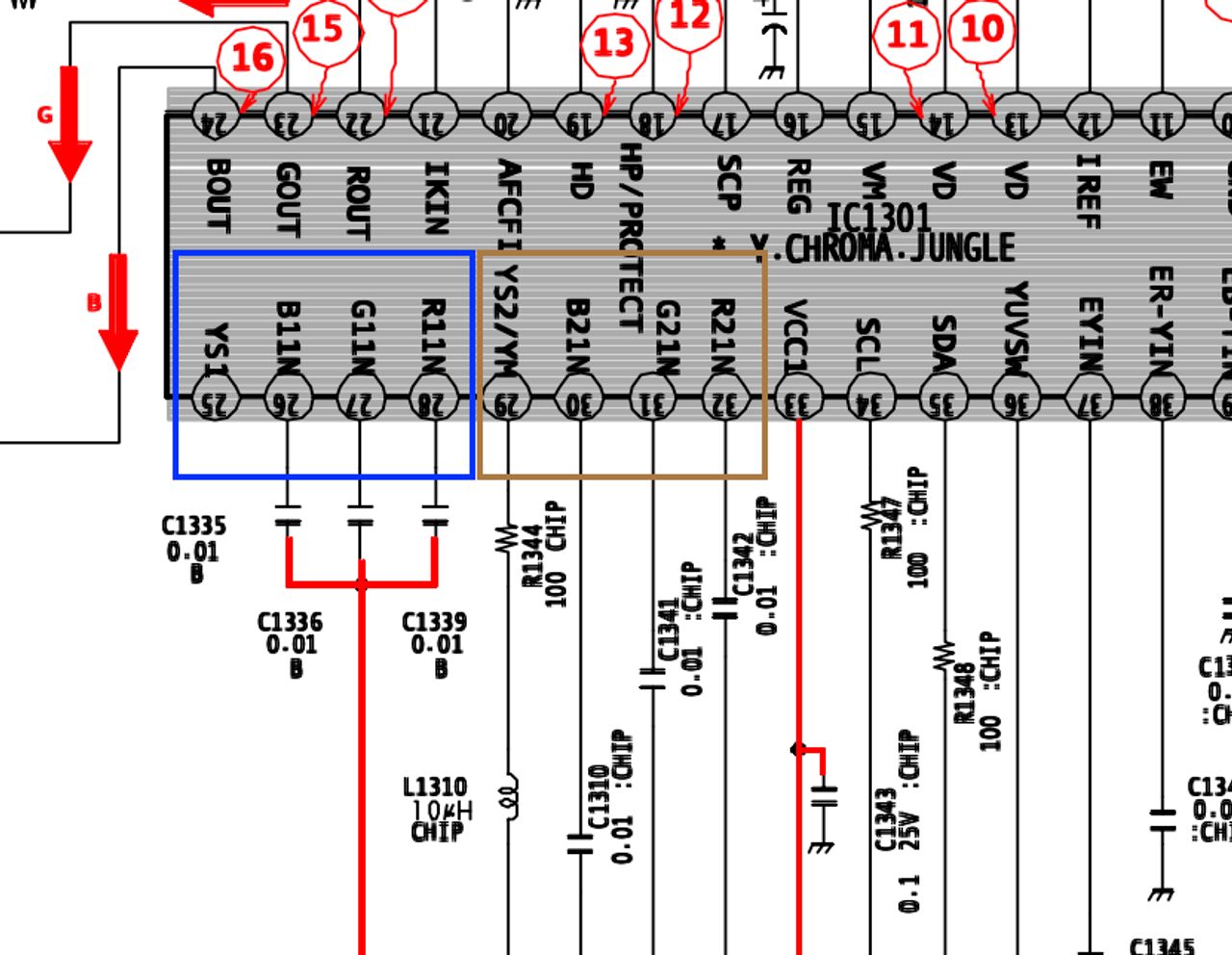
Prepare the mux diagram. If you are building your own circuit, this diagram should help.
The jungle chip in this set has 2 RGB inputs, with R1/G1/B1 unpopulated. The OSD is using R2/G2/B2, and it's an easy candidate for a OSDMux mod. 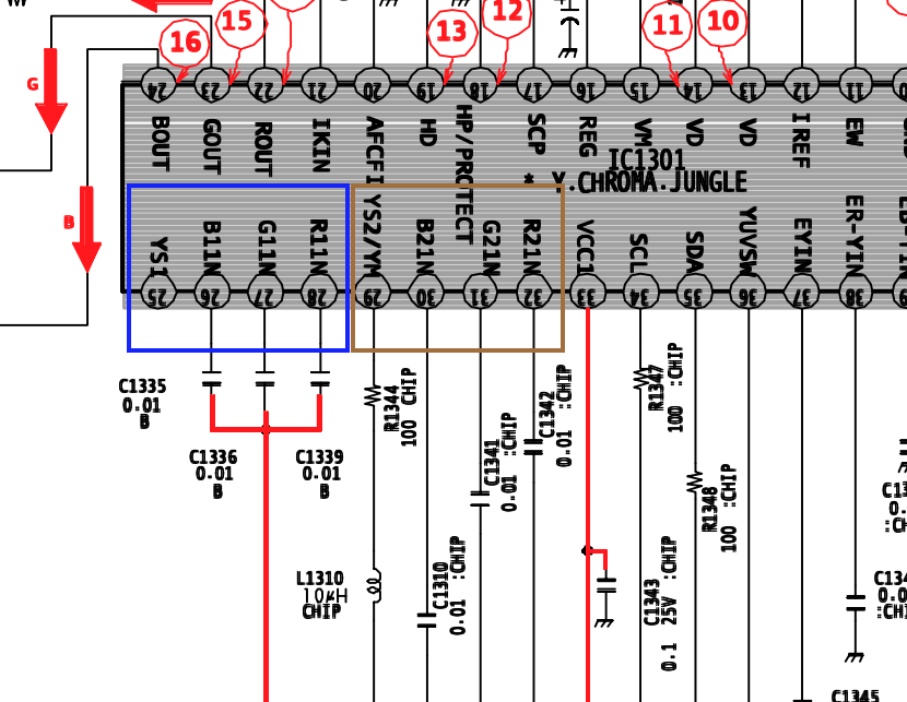 Given the fact that the OSD R2-G2-B2-Blank and the s-video Y signal are all exposed through jumper wires, I decided to go with an OSDMux mod.
Calculating the RGB external resistor value
To calculate the inline resistor values for the OSD-mux circuit, you can use the formula from the theory page:
RGB external resistor value (with diodes) = (0.7 x (6800 + 75) - (75 x 5)) / (5 - 0.7) = (4812 - 375) / 4.3 = 1030Ω
RGB external resistor value (no diodes) = (0.7 x (6800 + 75) - (75 x 5)) / 5 = (4812 - 375) / 5 = 887.5Ω
The voltage divider in the original schematics was producing ~0.5 Vpp so I decided to go with 680Ω and no diodes, that will make the internal OSD signal around 5 x ((680 + 75) / 6800) = 0.55 Vpp
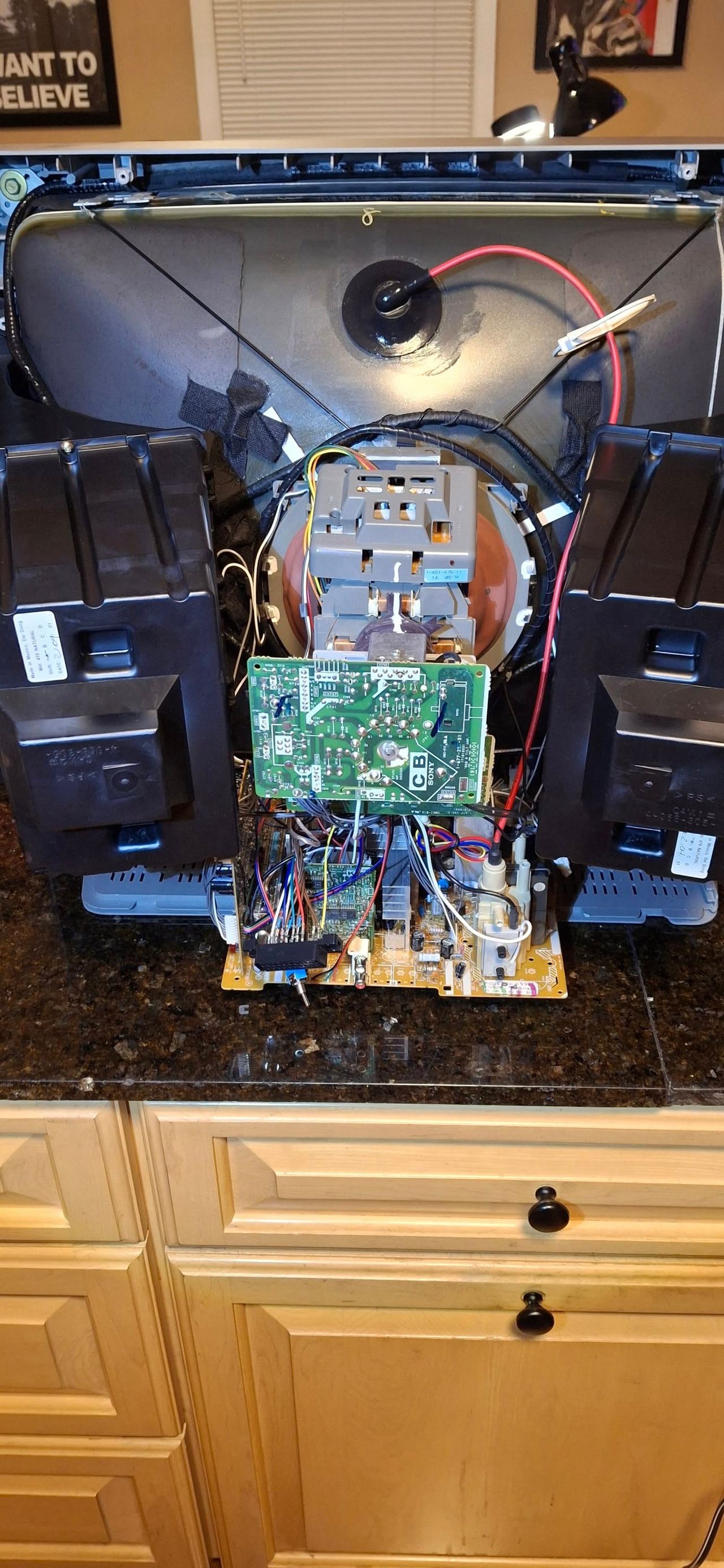
Performing the mod
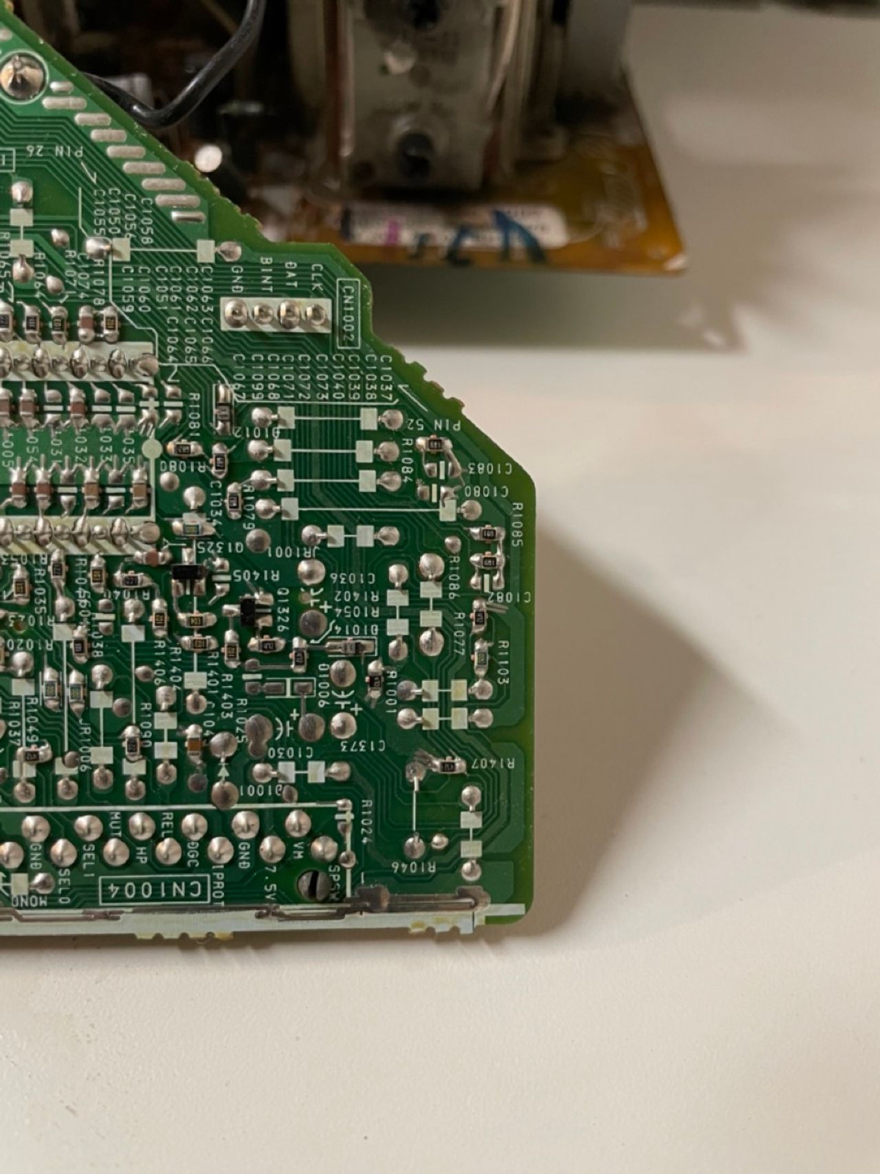
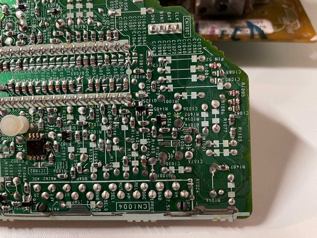
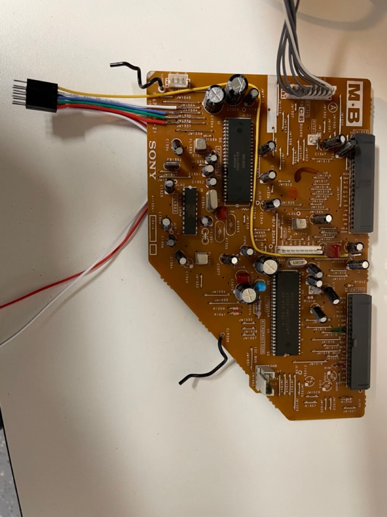
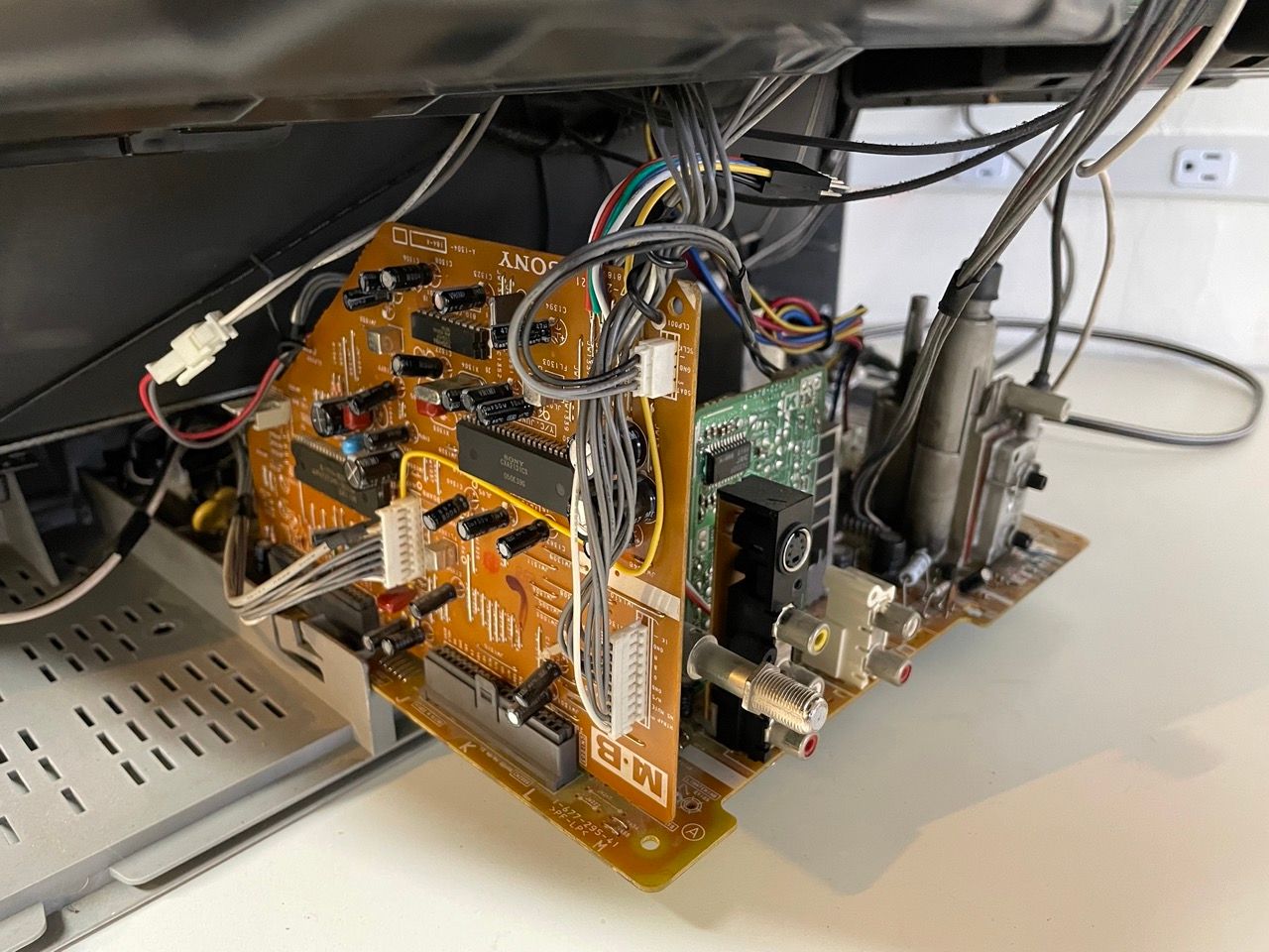
Now that you roughly know what needs to be done, prepare for the mod. For the TVs with a BA-5 chassis, the mod can be done entirely in the MB board: 
Disconnect the MB board and perform the following steps
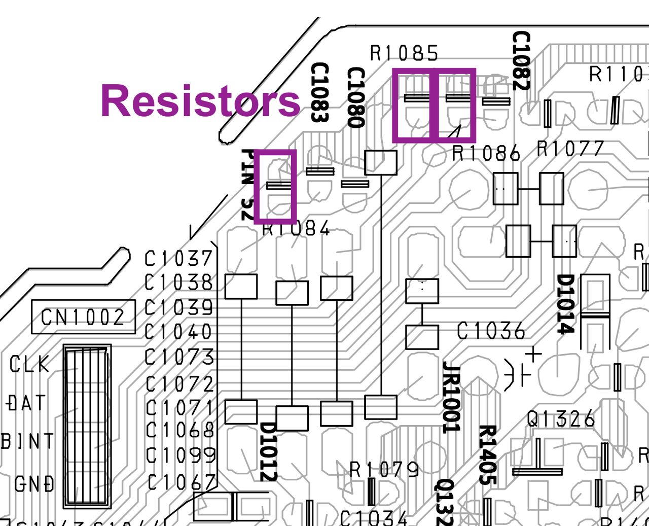
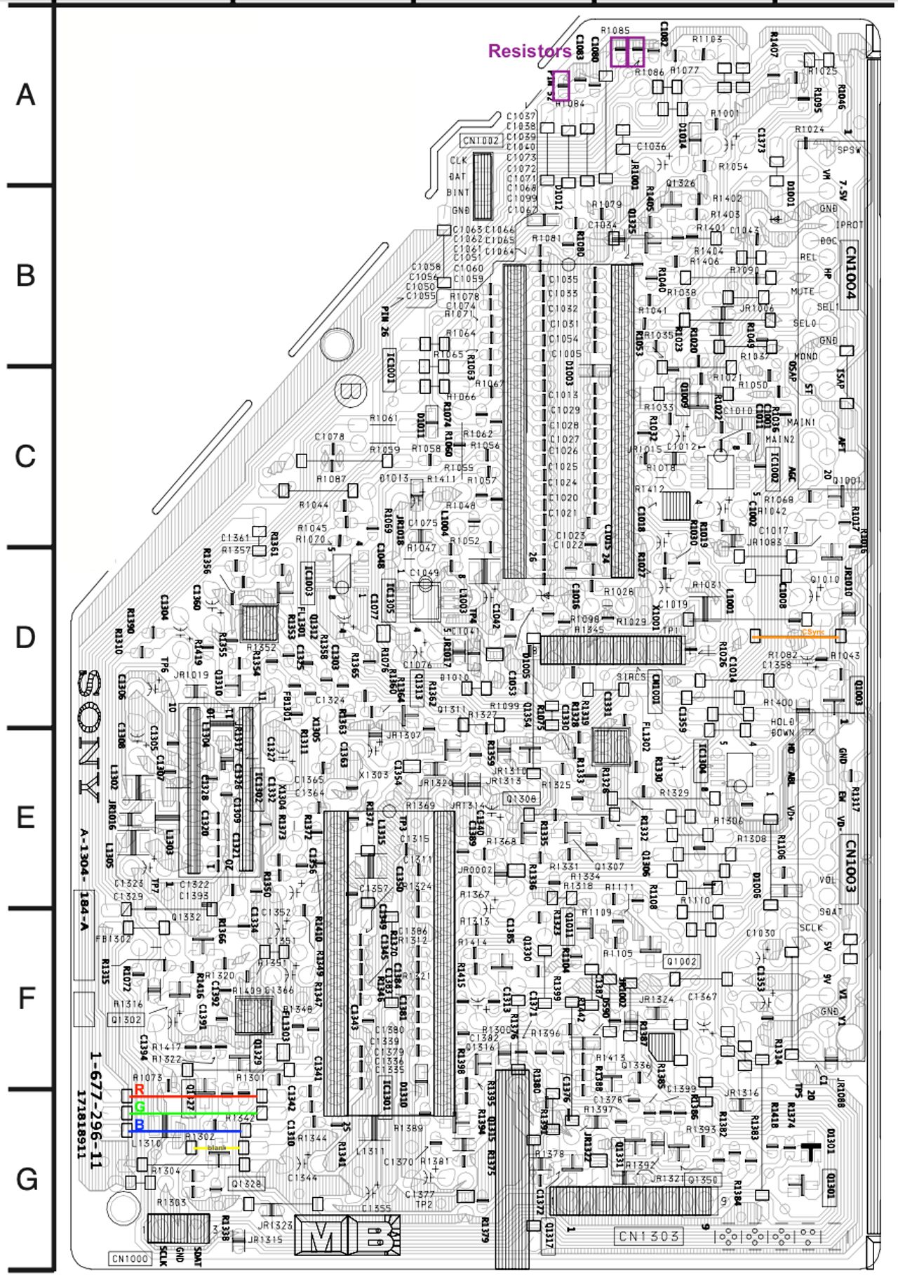
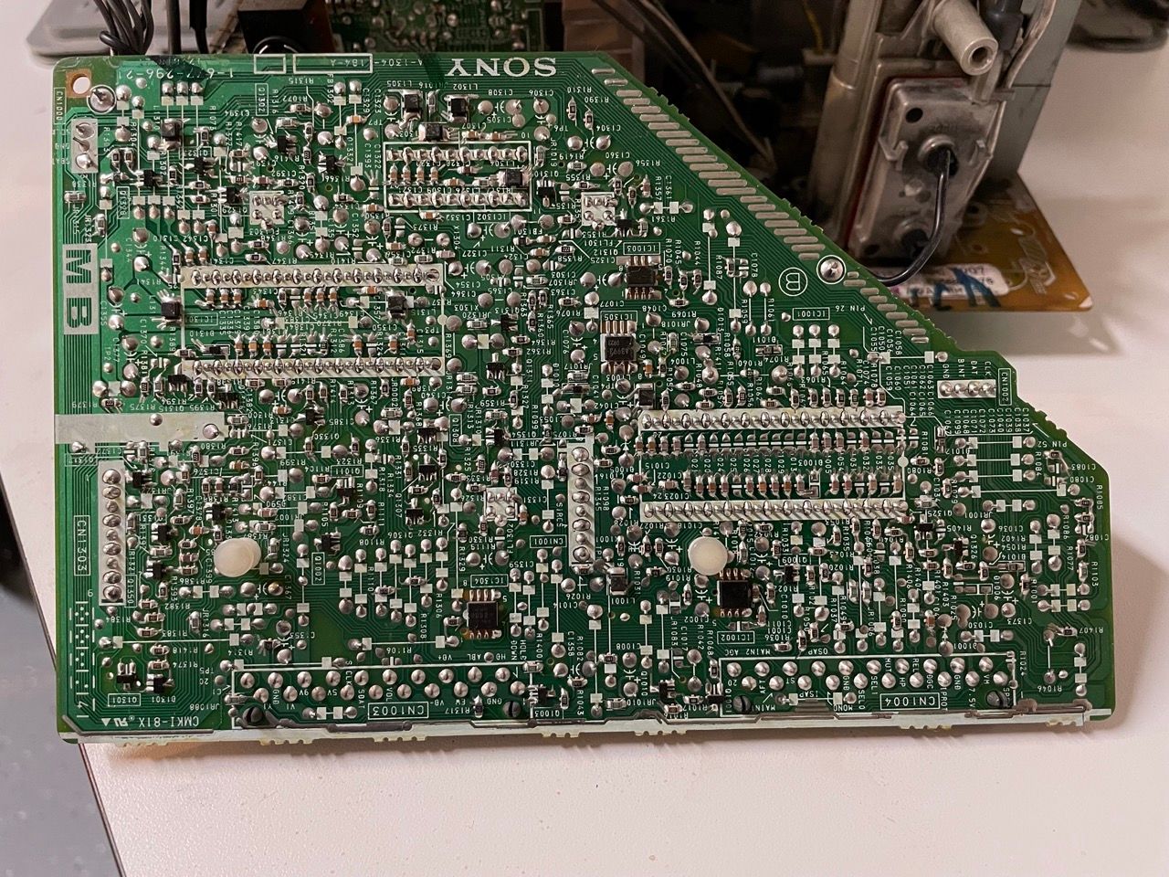
STEP 1: Remove the following components
Remove the ground resistors
- R1084 (680Ω)
- R1085 (680Ω)
- R1086 (680Ω)


STEP 2: Connect RGBs, Blanking and Audio
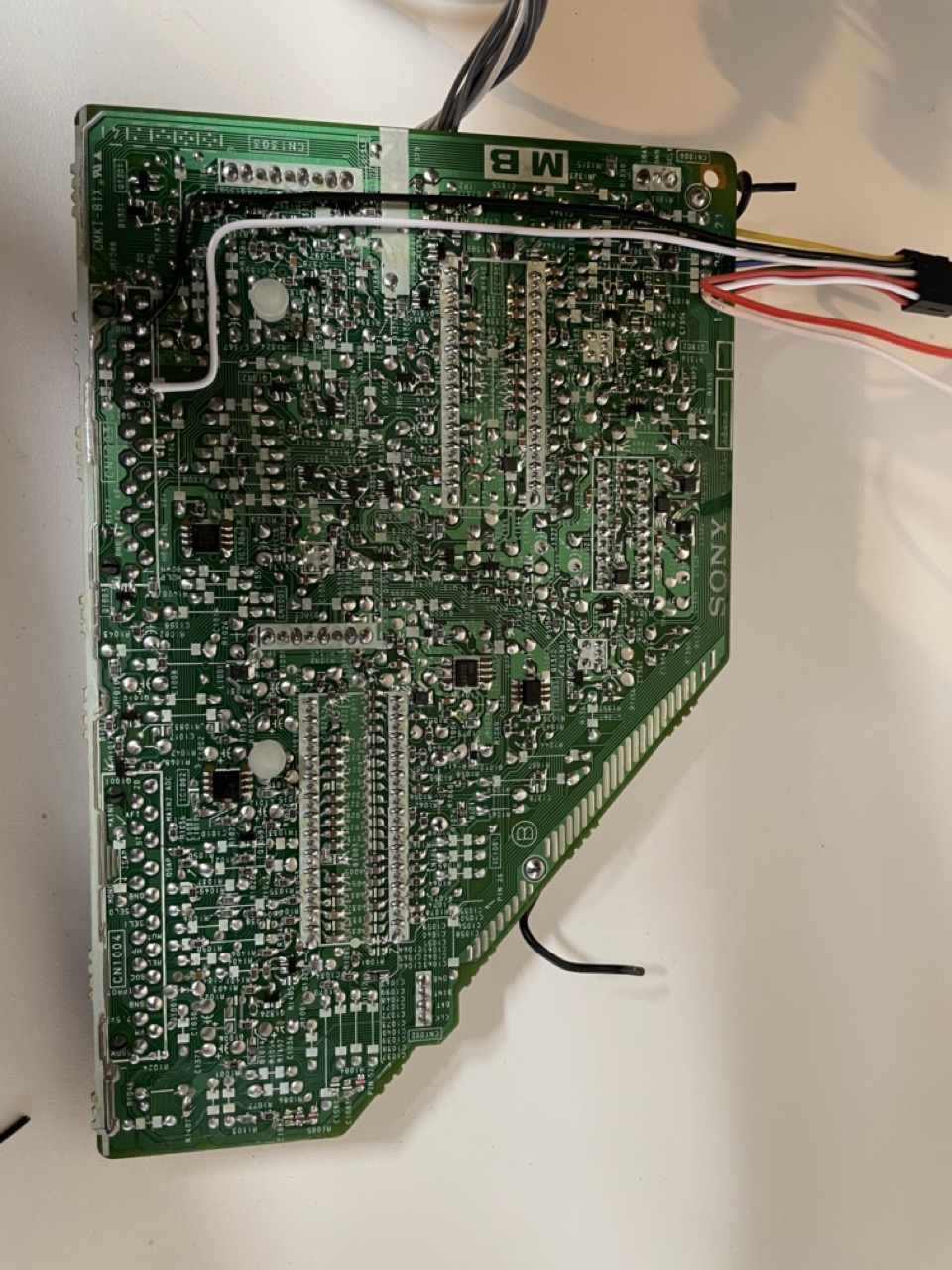
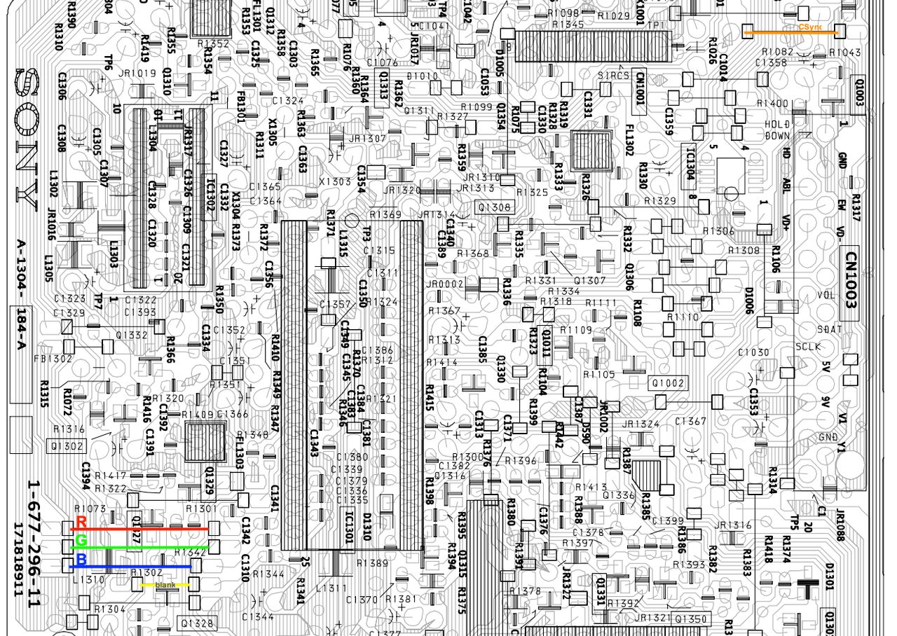
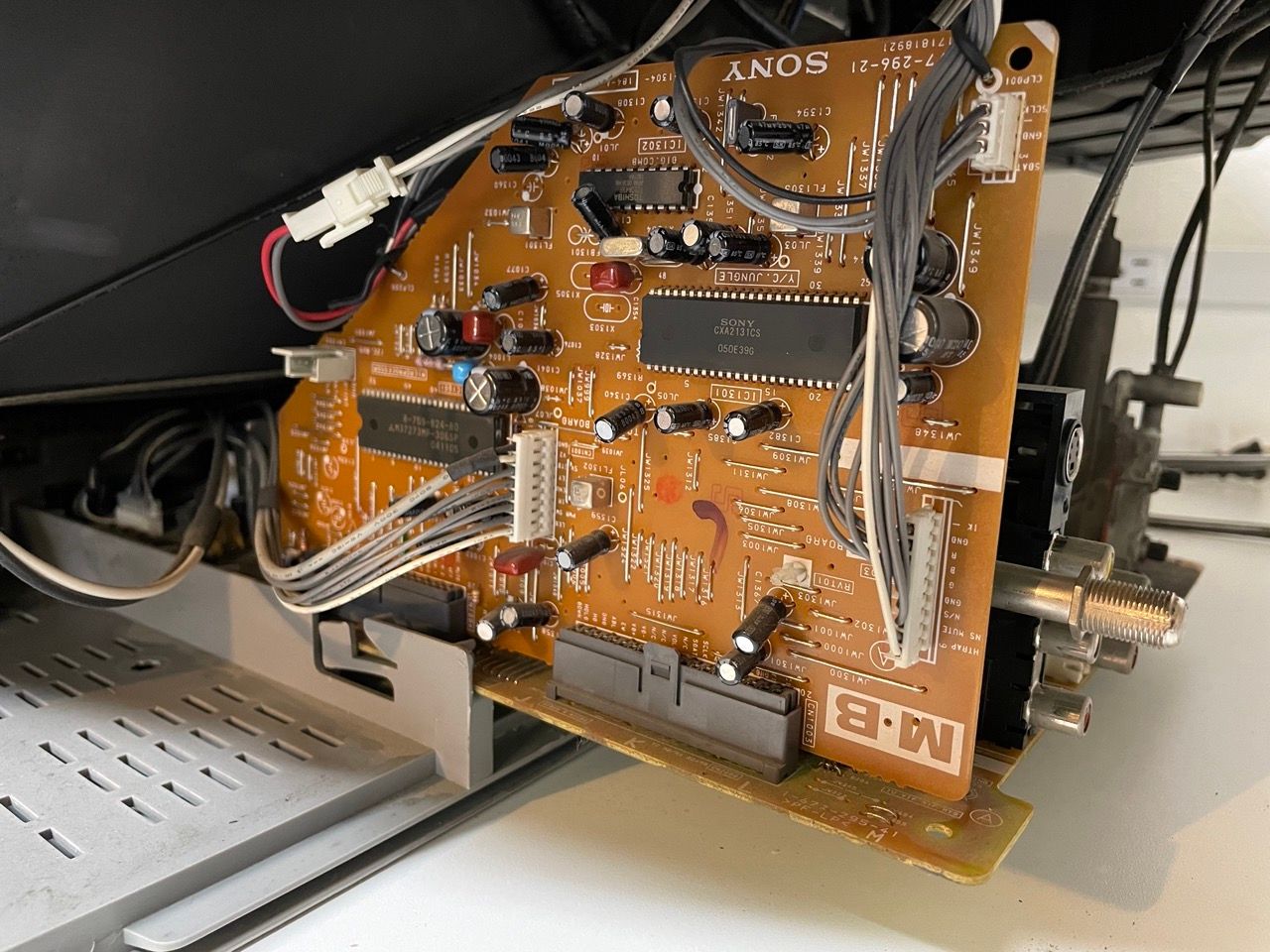
The following picture shows where to inject the RGB, Blank and CSync signals: 
In case you want to add diodes, remove the jumper wires marked with R G and B and replace them with 3 1N4148 diodes. Pay attention to the direction of the diodes. There is a black bar indicating which way the current flows. Then attach the R, G, B wires to the respective legs of the diodes. Wires should be attached to the side closer to the jungle chip. 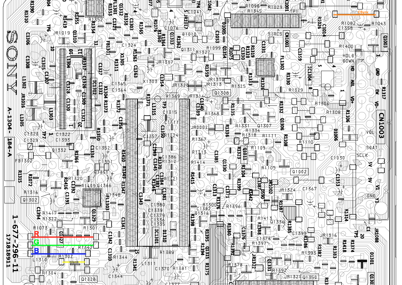
This helps reduce feedback noise and voltage going back into the OSD.
For the blank I used a 1N4148 diode; this is optional and there are already diodes in the schematic, but in my case I wanted to auto-commute through scart and I wanted to prevent any current from the TV to go back through the scart.
If you are doing a mod with RCA connectors you are more or less done, but if you want to use a SCART connector, you also have to inject CSync and Audio L/R signals.
The Sync sygnal can be connected to the s-video Y input in the MB board, close to the CN1003 connector in the image above.
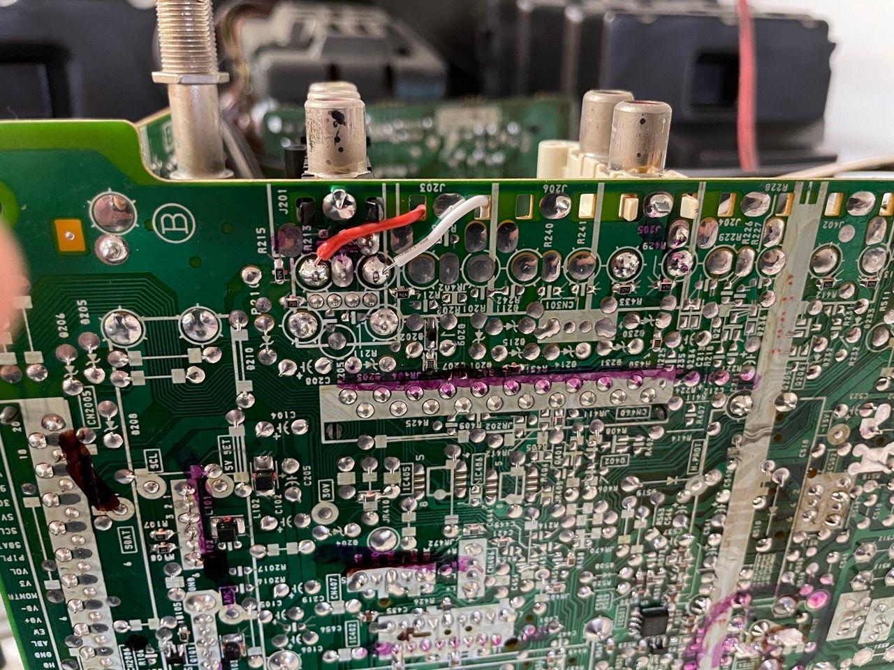
The audio has to be connected on the bottom of the RCA inputs in the A main board: 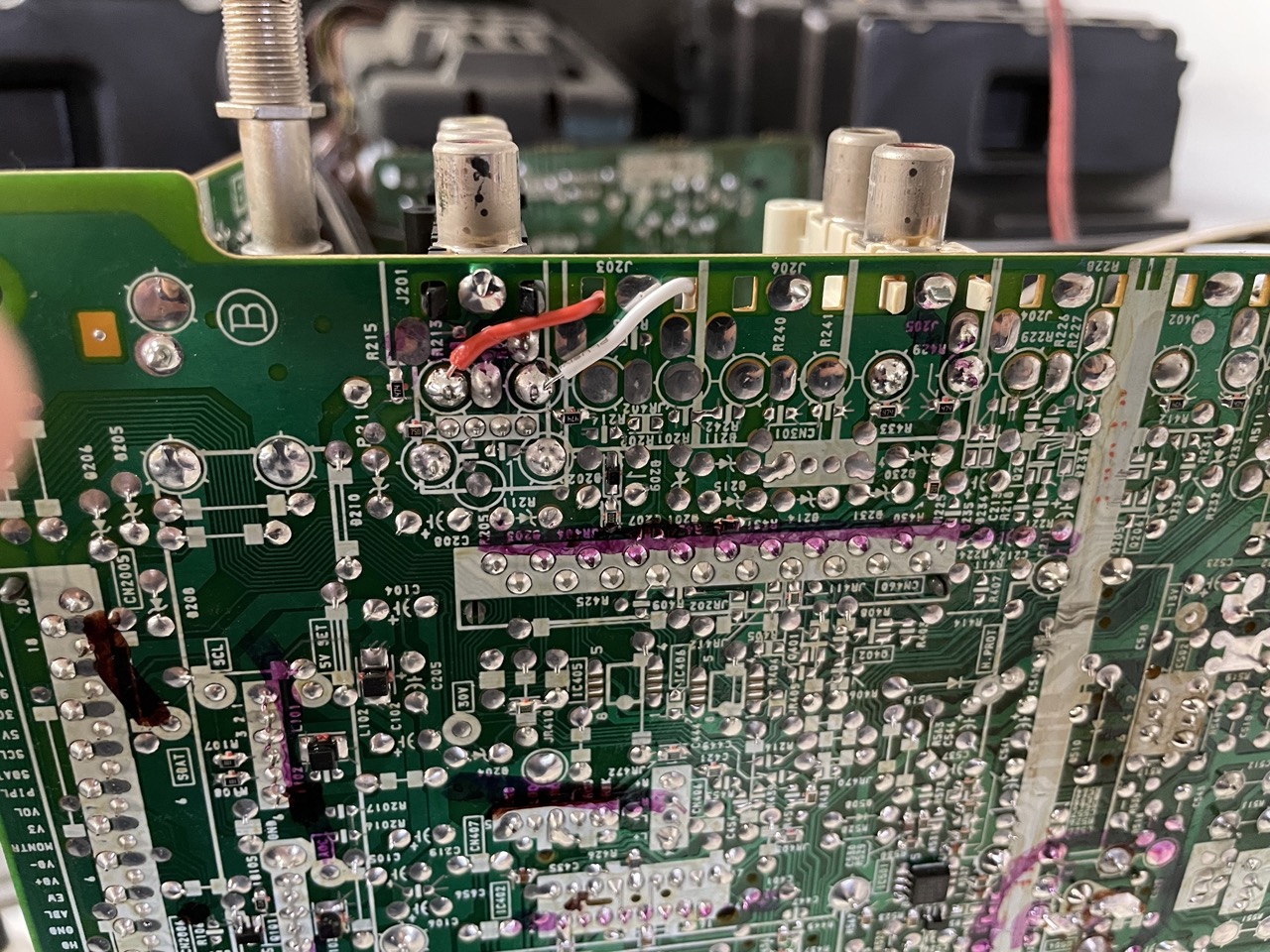
It's recommended to also connect the audio ground (not shown in the image above) and twist the audio wires to reduce the possible risk of interference.
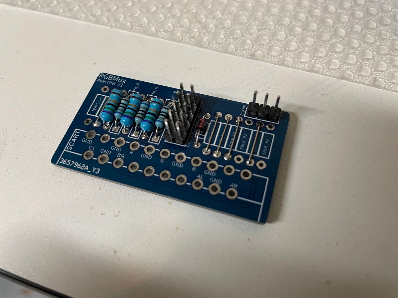
STEP 3: Build your mux board
Below mod uses a RGB mux board. This is optional, but will make your mod easier and stable. You can also create the circuit presented in the schematics above without the board. Please also checkout the precalculated resistor values.
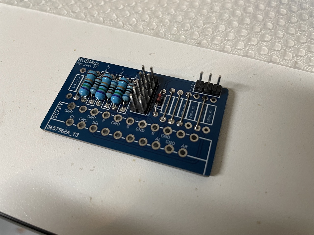
- TV Model: KV-24FV12
- Audio LR: Shorted
- RGB termination (TERM_R, TERM_G, TERM_B): 75Ω
- RGB inline resistors (INL_R, INL_G, INL_B): 680Ω
- Blanking Diode: 1N4148
- Blanking Resistor: shorted
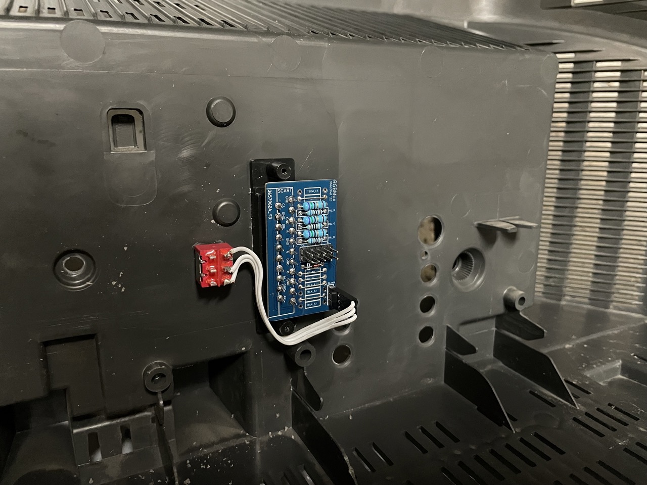
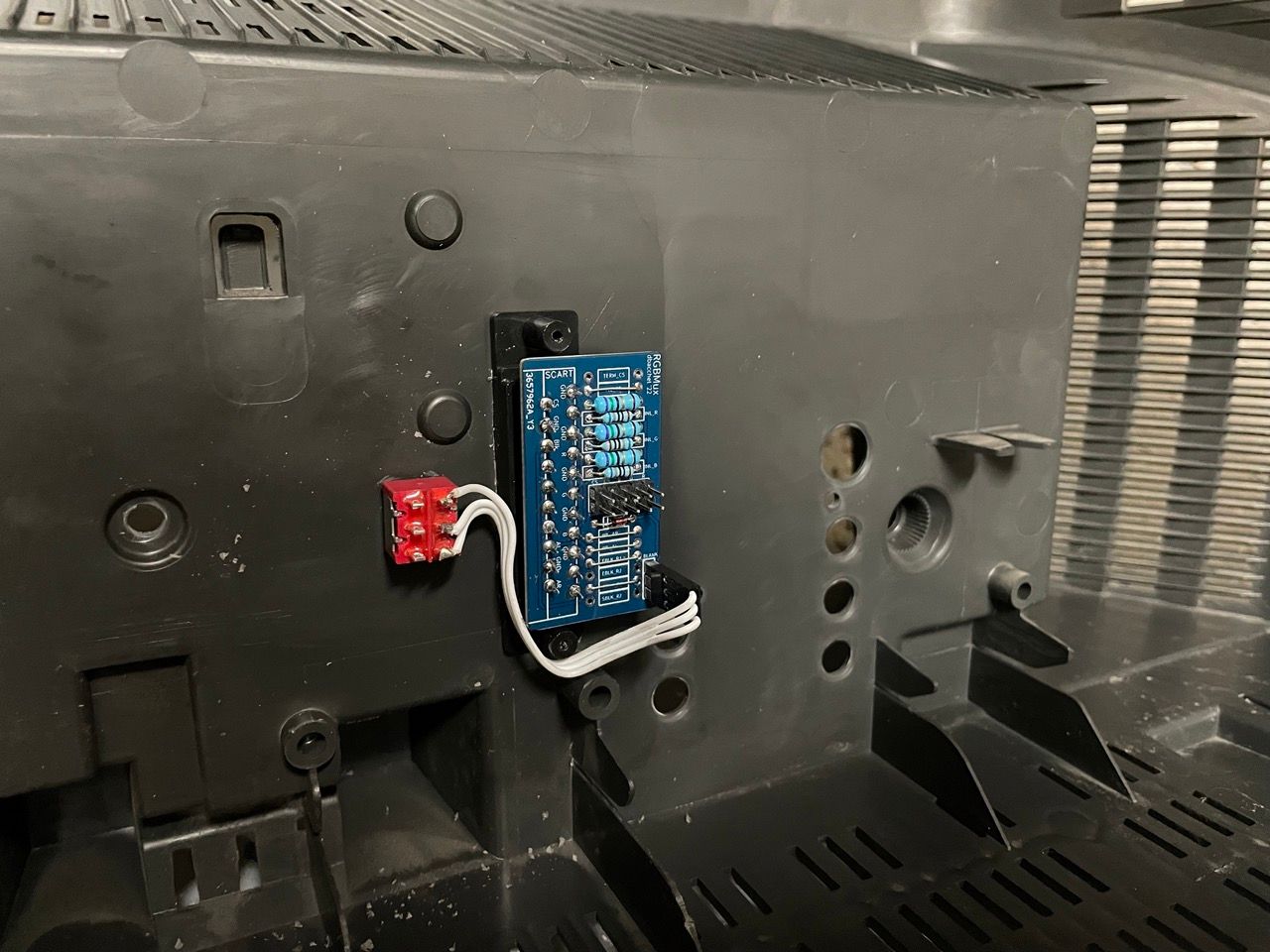
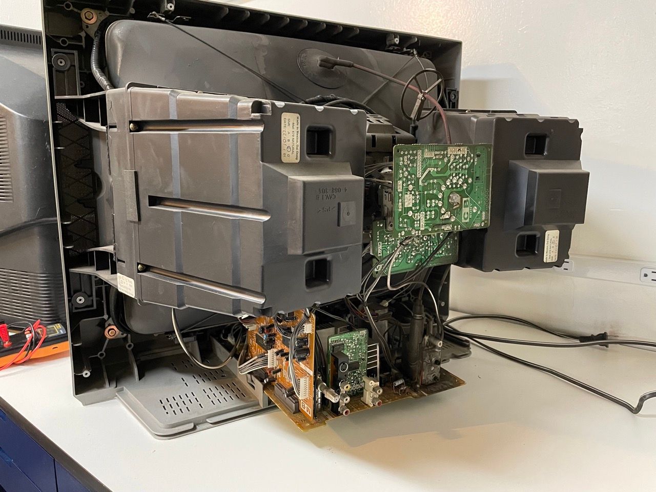
The board with the SCART connector can be installed on the back plastic cover, between the RCA connectors and the flyback:
Here is an alternate tutorial for the BA-5 chassis by Sunthar.
If you are using Sunthar's mux board you will be using the following configuration:
This mod uses the RGB mux board. This is optional, but will make your mod easier and stable. You can also create the circuit presented in the schematics above without the board. Please also checkout the mux calculator to play with your own values.
| On Sony CRT Chassis | KV-24FV12 |
|---|---|
| CRT RGB inline resistor | 6.8kΩ |
| CRT RGB ground resistors removed | 680Ω |
| 0.1μF caps replaced | No |
| Add diodes on chassis RGB lines? | Yes |
| Add blanking diode on chassis | No |
| RGB mux board | KV-24FV12 |
|---|---|
| Mux board RGB termination (R1, R2, R3) | 75Ω |
| Mux board RGB inline resistors (R4, R5, R6) | 1kΩ |
| Mux board Audio LR (R7, R8) | 1kΩ |
| Mux board blanking diode (R9) | 1N4148 |
| Mux board blanking ground resistor (R10) | open |
| Mux board blanking resistor (R11) | 1kΩ |
| Mux board transistor base resistor (R12) | 1kΩ |
| Mux board transistor (Q1) | PN2222A |
Getting into the service menu
It's recommended to access the service menu and tune image size and position.
- Turn the set on and then put into standby
- Press the Display, 5, VOL + buttons in sequence
- Turn on the CRT and you should be in service mode
- Use buttons "1" and "4" on the remote control to navigate the service menu
- Use buttons "3" and "6" to adjust the selected data
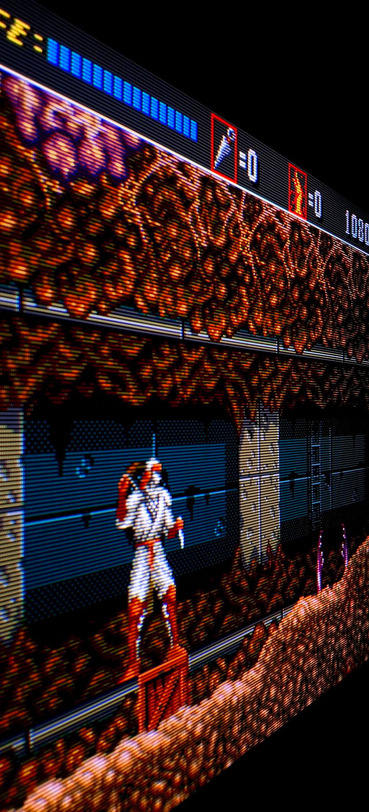
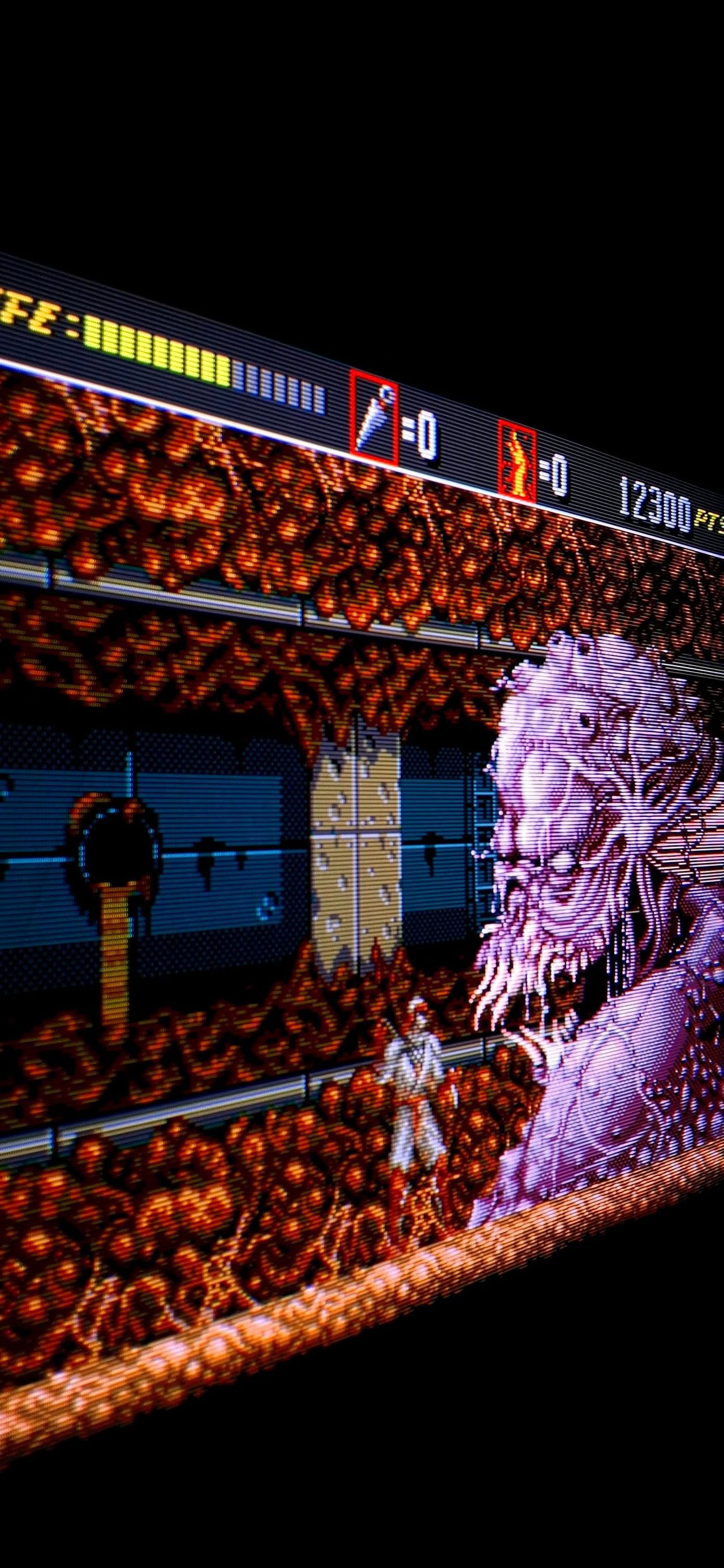
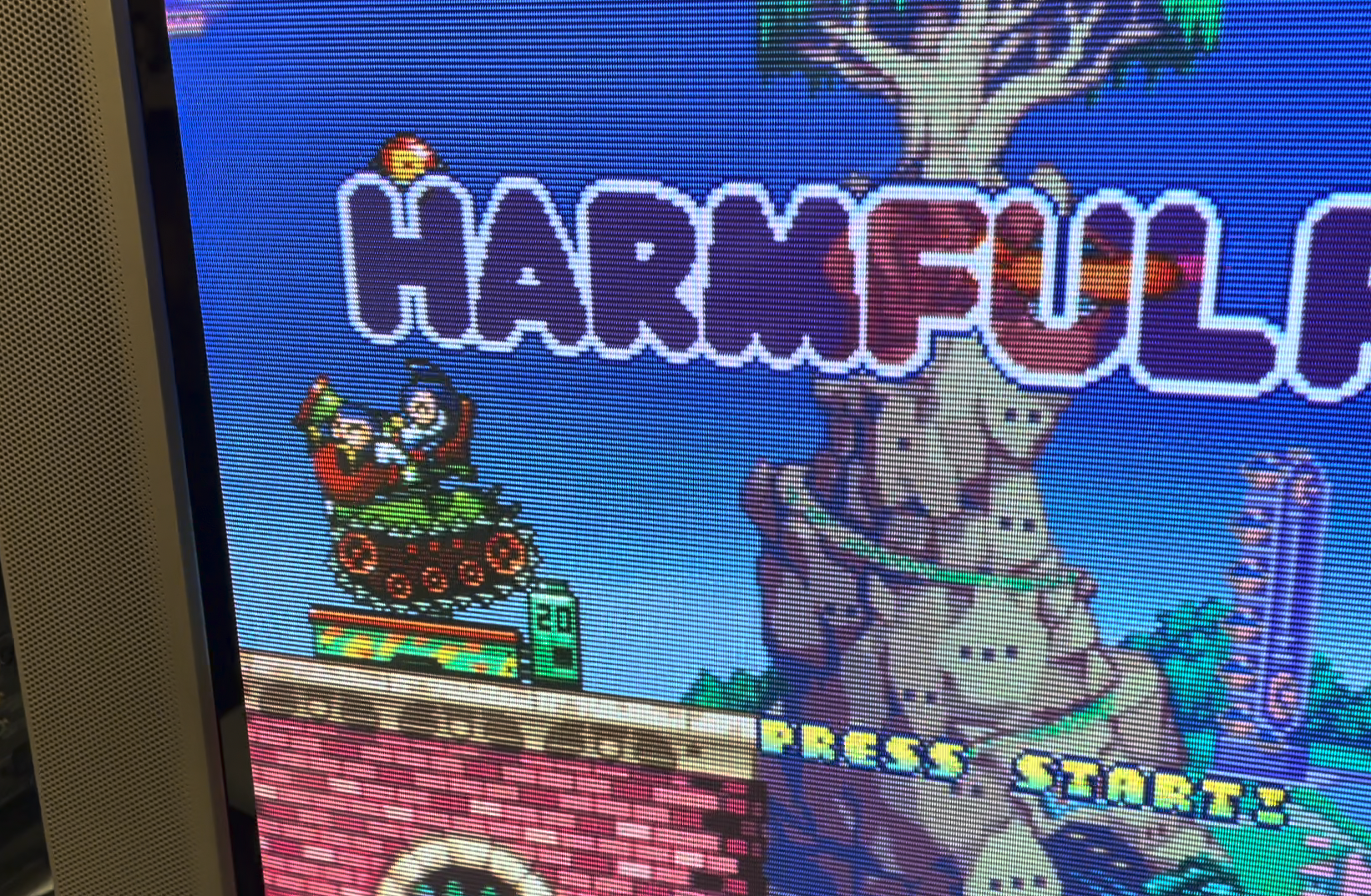
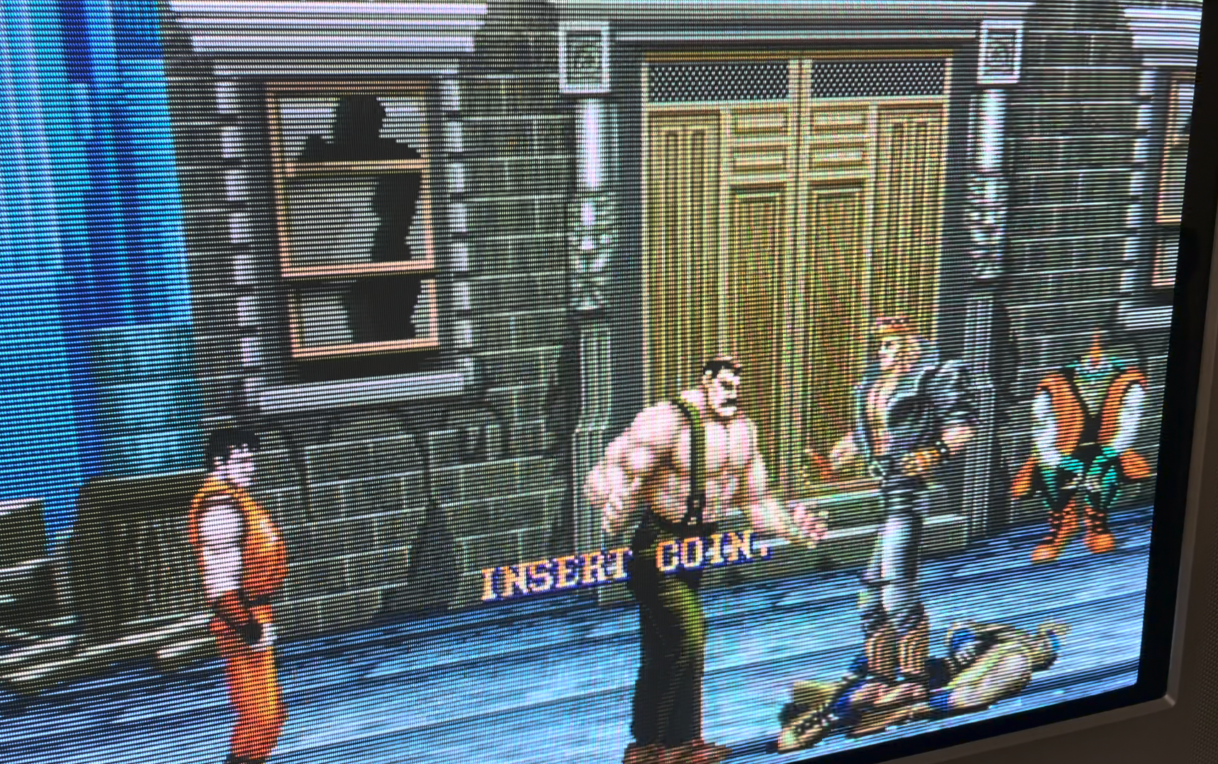
Pictures of the mod


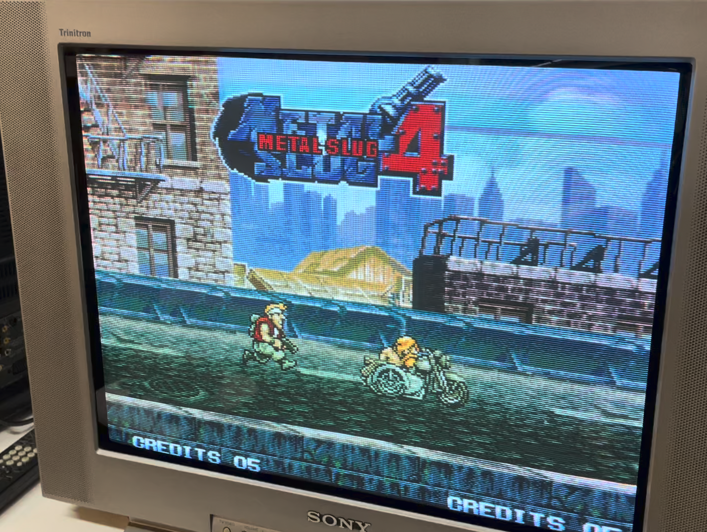
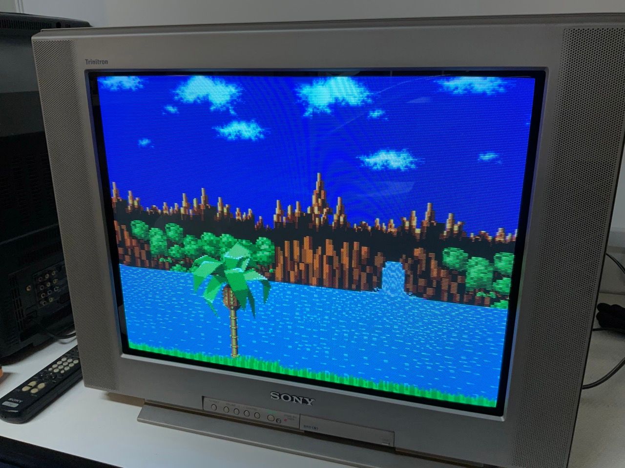
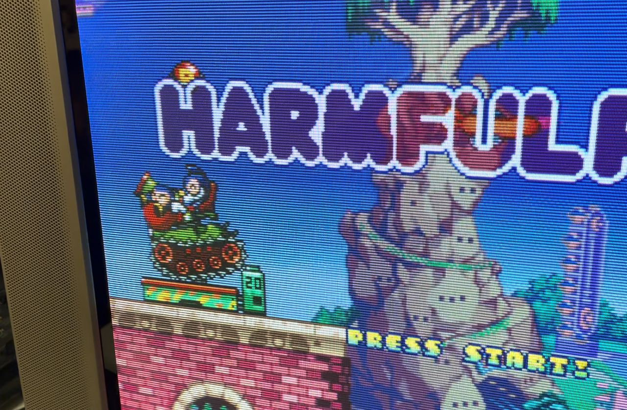
Games
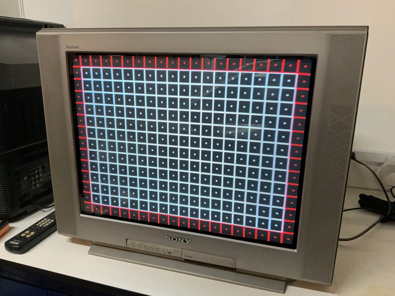
Patterns
Pictures
Mod Photos
This tutorial should also cover the RGB mod for the below models with the BA-5 chassis. However, there might be slight differences.


Reference Photos