Sony (ANU-2) KV-20EXR20
Sony (ANU-2) KV-20EXR20 CRT RGB mod
The Sony KV-20EXR20 is a 20-inch CRT display, featuring the A51JUH50X tube. Weighing in at 55 pounds, the KV-20EXR20 is built with a plastic cabinet and includes stereo speakers.
This CRT is modifiable for RGB input via direct injection, making it appealing for enthusiasts.
View full CRT details and more mod examples →
Other ANU-2 chassis based models can also utilize the same mod, with some exceptions.
- KV-20EXR10
- KV-20EXR15
- KV-20EXR20
- KV-27EXR10
- KV-27EXR15*
- KV-27EXR20
- KV-27EXR25*
- KV-27EXR90 (RGB mux mod doesn't seem to work on KV-27EXR90. It seems as if the second set of RGB inputs are disabled through F/W, i2c.)
- The P-Board for Picture-in-Picture functionality must be removed in these models.
Contributors
Thank you to everyone who contributed to this guide:
- Andy King — contributor, CRT specs from CRT Database.
- Kaz Packman — contributor, RGB mod tutorial and pictures
CRT safety
Caution
You can die doing this! So read carefully! CRT TV is not a toy. Do not open a CRT TV. If you don't have any prior knowledge about handling high voltage devices, this guide is not for you. CRT TV contains high enough voltage (20,000+ V) and current to be deadly, even when it is turned off.
Plan of attack
Manuals and Datasheets
Specs
- Manufactured: Mexico (1991, 1992)
- Format: NTSC
- Chassis: ANU-2
- Tube: Sony Trinitron A51JUH50X
- Jungle Chip: Sony CXA1313S
- OSD Chip: M37100M8-115SP
- Screen Size: 20"
- Inputs: Composite, S-Video, RF
Schematics
SCART schematics
BNC schematics
RGB mux diagram
Prepare the mux diagram. If you are building your own circuit, this diagram should help.
Performing the mod
Please note below mod uses an external switch for the 5V.
STEP 1: Add resistors
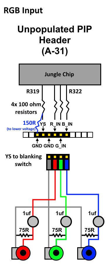
Locate the empty resistor spots labeled R319, R320, R321, and R322 near IC301, add 100 ohm resistors into them. Add a 150 ohm grounding resistor between R319 and one of the ground pads on the unpopulated A-31 header, this will act as a voltage divider for our blanking circuit.
Add 100Ω and 150Ω resistors 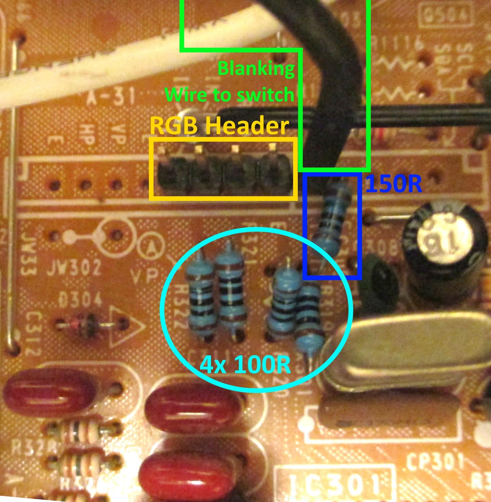
100Ω resistors 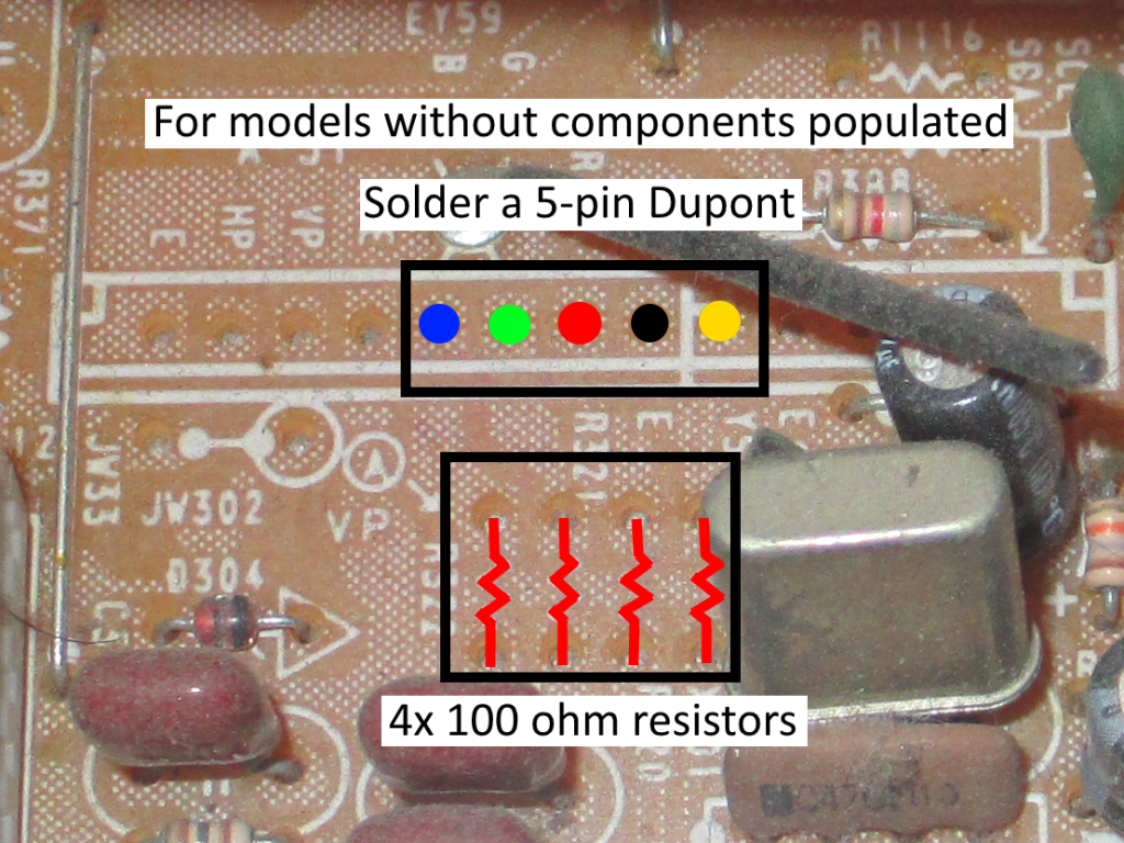
150Ω resistor 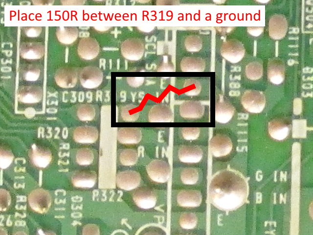
STEP 2: Add a header
Populate the A-31 header with a 5-pin male DuPont header connector in the pins labeled "B IN", "G IN", "R IN", "E", and "YS". The first four pins mentioned will be for ground and RGB, and the "YS" pin will be for blanking.
STEP 3: Blanking wiring
Run wires from the output of the 5V regulator (TP96A near the tuner would be the perfect place) and the "YS" pin of A-31 to your blanking switch on the middle and right pins repectively.
![]()
Alternatively, you can also use the 5V from pin 16 of the SCART connector for blanking.
STEP 4: Prepare RGB connector
Wire your RGB connectors to a 4-pin female DuPont connector for the A-31 header with 0.1 uF ceramic capacitors inline and 75 ohm resistors terminating the RGB connectors to ground.
STEP 5: Optional if not using SCART
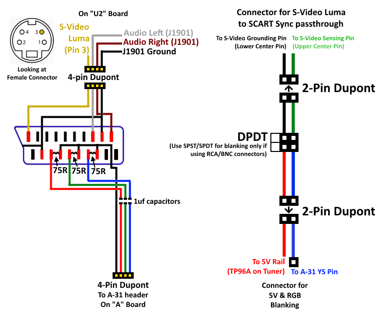
Run wires from the S-Video Luma pin, both Audio signal pins, and the ground of the VIDEO 1 jacks (labeled "J1901") on the U2 board to the SCART connector. Refer to the diagram for the pin arrangement. Bear in mind that there is a metal shield that covers this board upon reassembly, so take care when routing your wires.
To enable the S-Video input as a Sync source for your SCART connector, you must trigger the sensing circuit. You can do this either by running a jumper wire from the Sense (upper center pin) and Ground (lower center pin) of the S-Video connector, or by wiring those pins to the second pole of a DPDT switch.
STEP 6: MUX board or RCA
Go into the service menu and adjust the horizontal position (labeled "HPOS" in the service menu) until it looks properly centered. If you're inputting sync into the S-Video input, you should only have to adjust it by about 2 or 3 subtracted from the original value.
If you're using RCA or BNC jacks for RGB, sync should be input to the S-Video input via an adapter. This will reduce the horizontal shift on your RGB image.
You can also use the mux board as specified below
This mod uses the RGB mux board. This is optional, but will make your mod easier and stable. You can also create the circuit presented in the schematics above without the board. Please also checkout the mux calculator to play with your own values.
| On Sony CRT Chassis | KV-20EXR20 |
|---|---|
| 0.1μF caps replaced | No |
| Add diodes on chassis RGB lines? | No |
| Add blanking diode on chassis | No |
| RGB mux board | KV-20EXR20 |
|---|---|
| Mux board RGB termination (R1, R2, R3) | 75Ω |
| Mux board Audio LR (R7, R8) | 1kΩ |
| Mux board blanking diode (R9) | 1N4148 |
| Mux board blanking ground resistor (R10) | open |
| Mux board blanking resistor (R11) | 1kΩ |
| Mux board transistor base resistor (R12) | 1kΩ |
| Mux board transistor (Q1) | PN2222A |
Compatible mux boards:
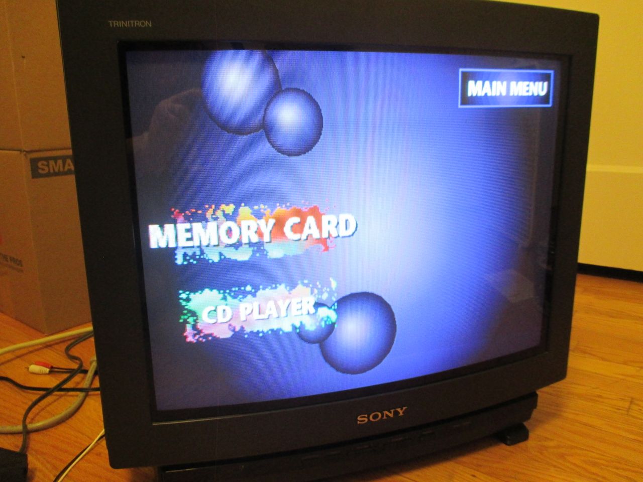
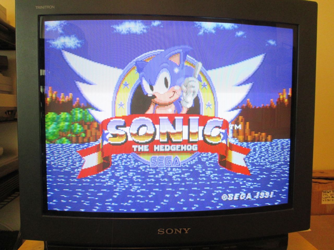
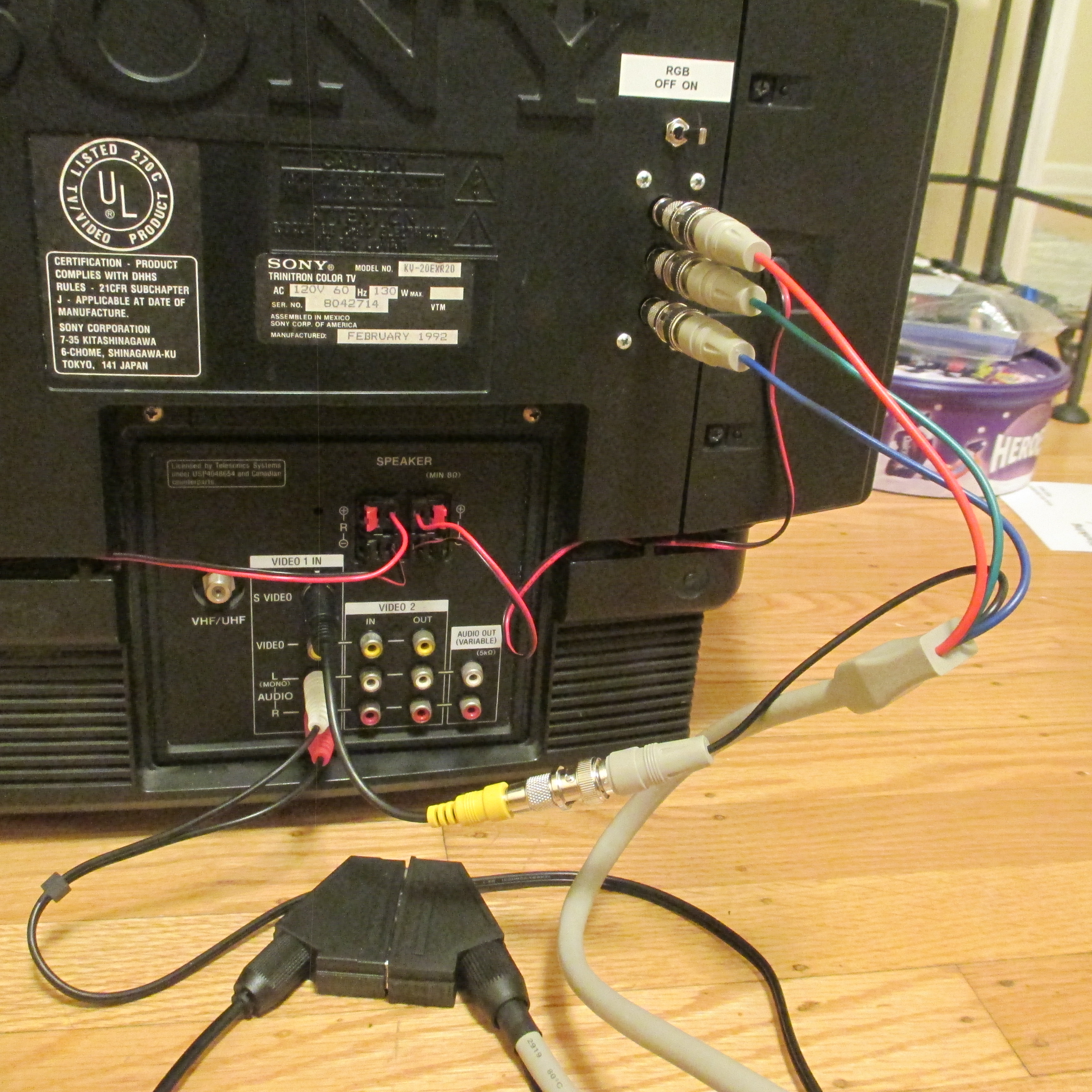
Pictures
Reference Photos
