JVC AV-32D202
JVC AV-32D202 CRT RGB mod
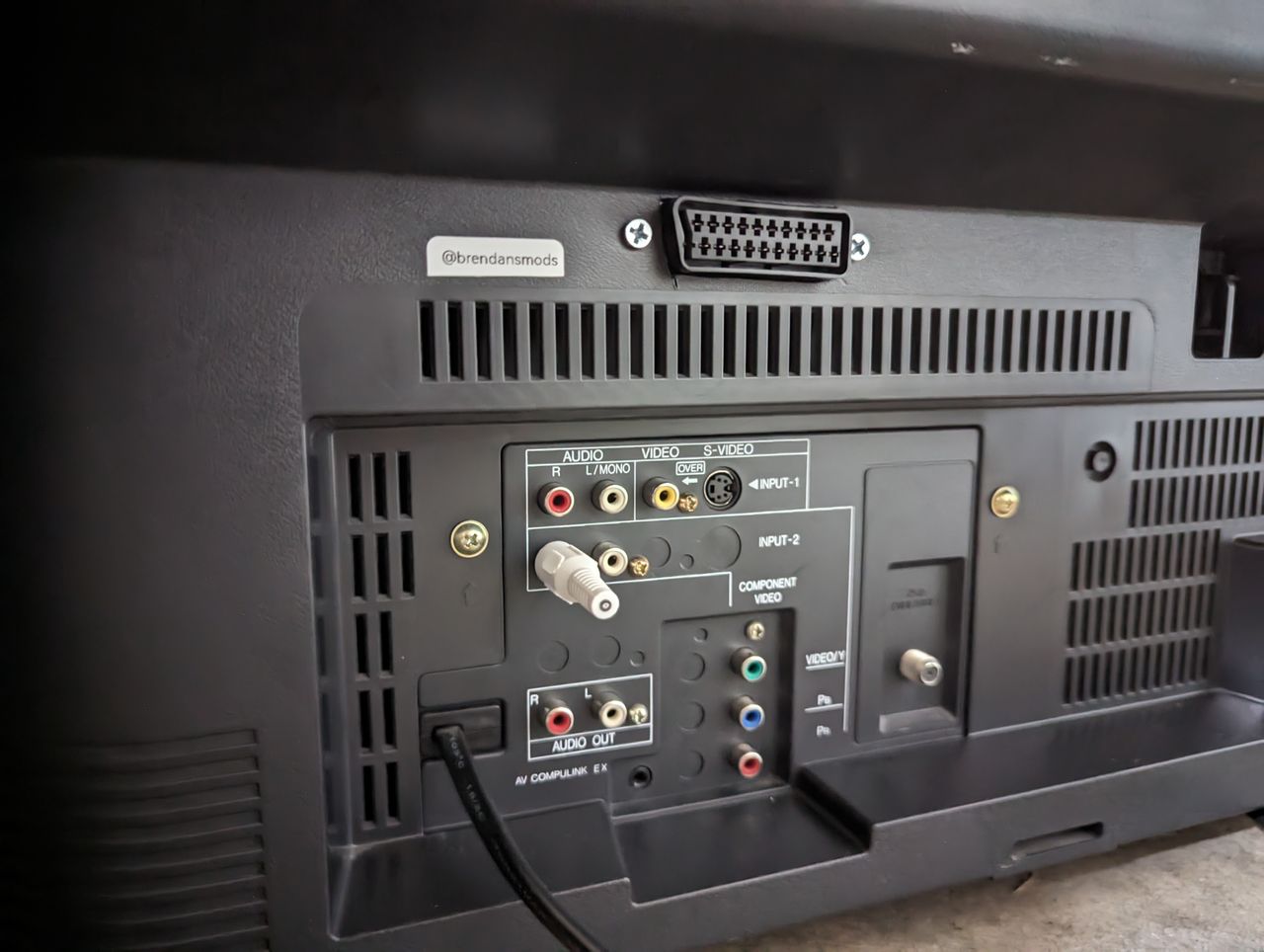
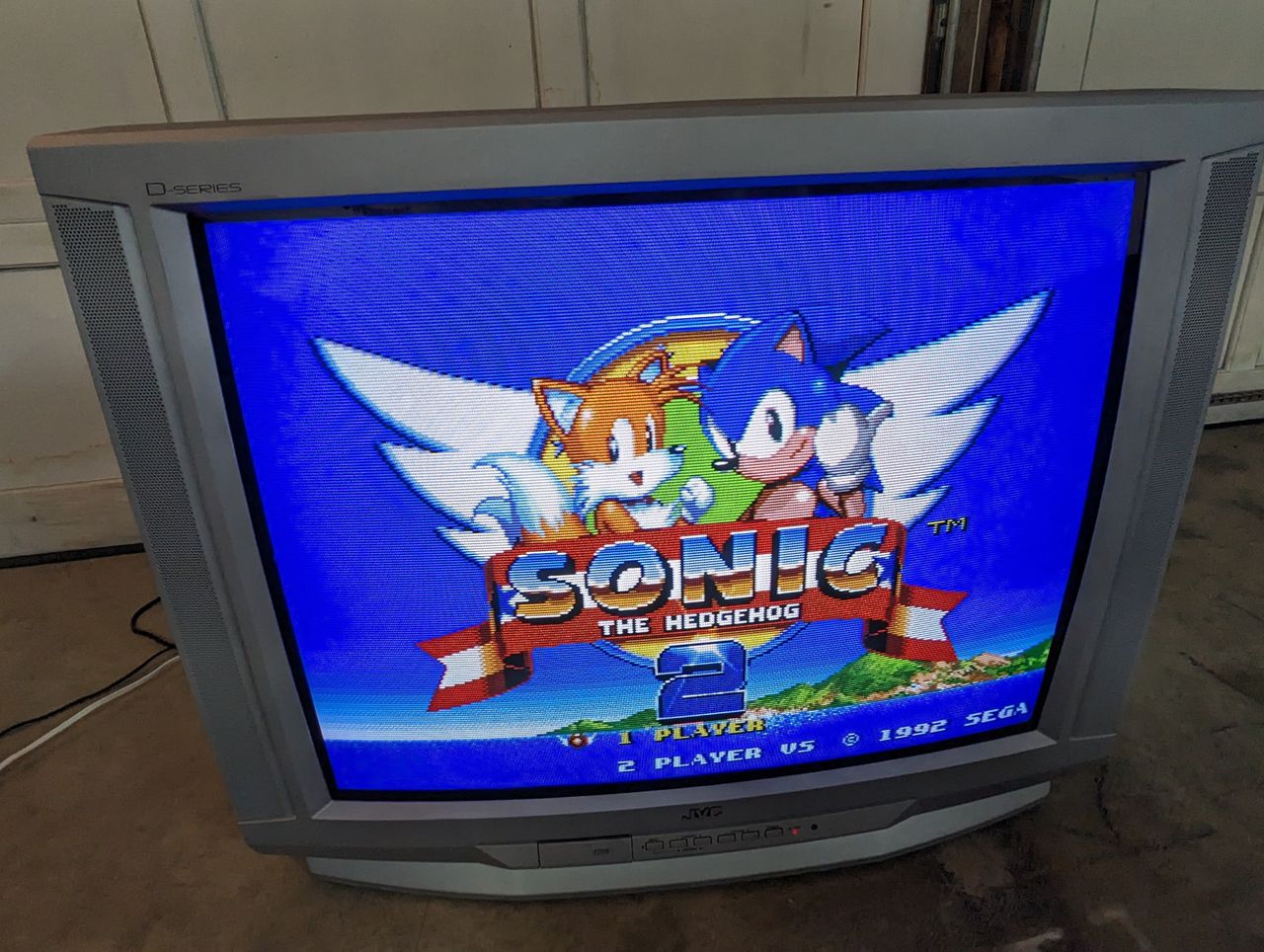
The JVC AV-32D202 is a 32" CRT television from the highly regarded "D-Series" line, produced in the early 2000s. It is widely recognized for its high-quality picture, featuring a curved shadow mask screen, component video inputs, and 700 lines of horizontal resolution.
View full CRT details and more mod examples →
This RGB mod should also apply to other similar JVC models with an AC chassis.
This JVC D-Series chassis includes support for analog RGB through the micom's OSD video signals. You can tap in between the OSD's output and the Y/C Jungle's input to inject your external RGB signals through a common connector such as SCART or BNC. In this guide we will be utilizing SCART, made easier with help of Sunthar's mux board, more on that later.
This mux mod will utilize the OSD circuit for RGB, Component Luma for sync, and direct connection with SCART pin 16 for blanking.
Contributors
Thank you to everyone who contributed to this guide:
- Brendan Eddy — author, RGB mod and pictures
CRT safety
Caution
You can die doing this! So read carefully! CRT TV is not a toy. Do not open a CRT TV. If you don't have any prior knowledge about handling high voltage devices, this guide is not for you. CRT TV contains high enough voltage (20,000+ V) and current to be deadly, even when it is turned off.
Plan of attack
Manuals and Datasheets
Specs
- Year: 2001
- Format: NTSC
- Chassis: AC
- Tube: Samsung
- Jungle Chip: Toshiba TB1253AN
- OSD Chip: MN1876478JL1
- Screen Size: 32"
- Inputs: Composite, S-Video, RF, Component YPbPr
RGB mux diagram
Prepare the mux diagram. If you are building your own circuit, this diagram should help.
Parts needed
- 4 x 1N4148 diodes
- 3 x 360 Ohm resistors
- 3 x 75 Ohm resistors
- 3 x 1k Ohm resistors
- 1 x 4.7k Ohm resistor
- 1 x SCART female port
- Plenty of different colored wire
- (Optional) Sunthar SCART mux board
Performing the mod
Now that you roughly know what needs to be done, prepare for the mod. Place the board on a comfortable place. Make sure you are not putting pressure on the flyback or other components.
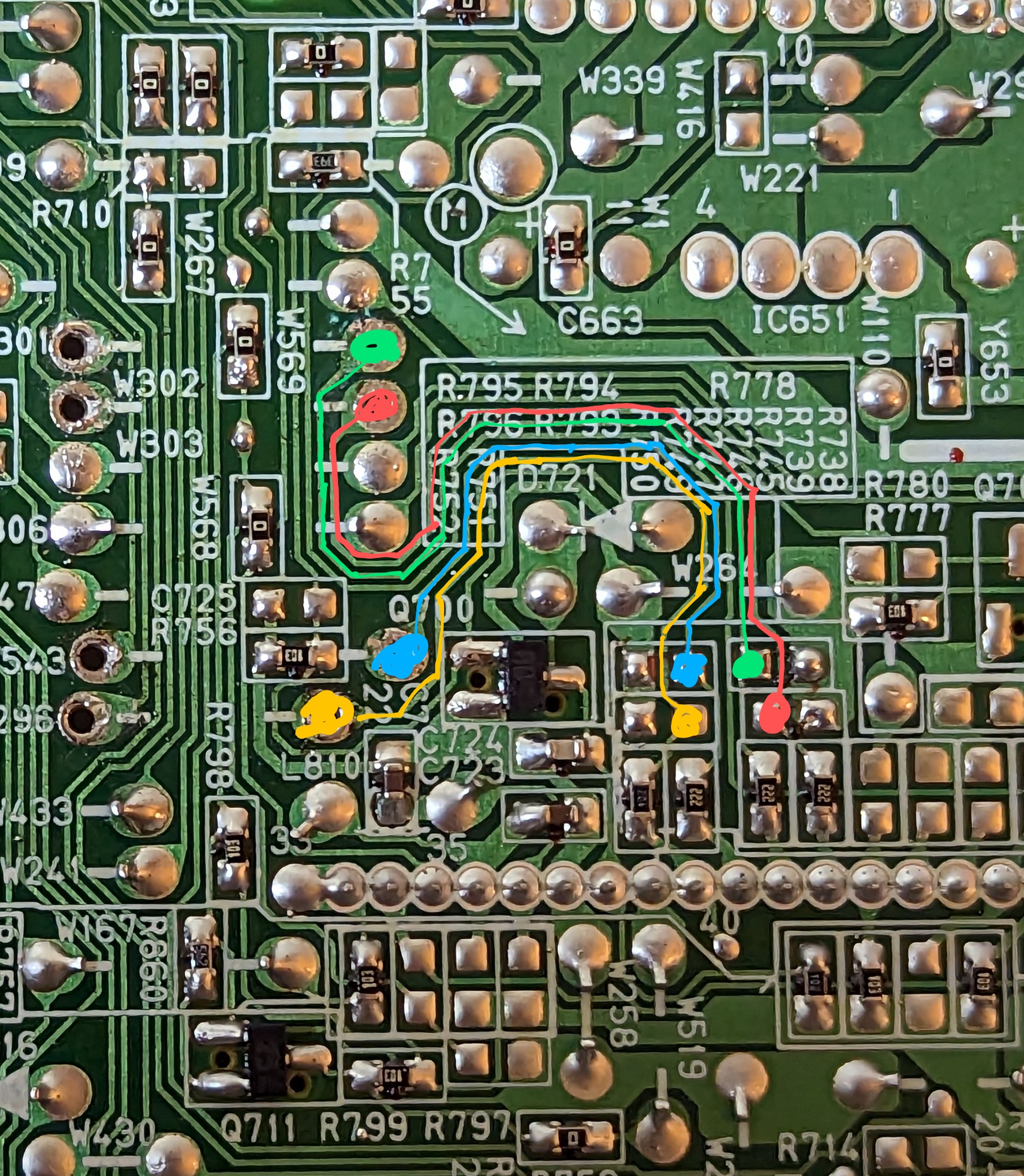
STEP 1: Remove grounding SMD resistors R793, R794, R795
- R793 (330 ohms)
- R794 (330 ohms)
- R795 (330 ohms)
Before removing the resistors 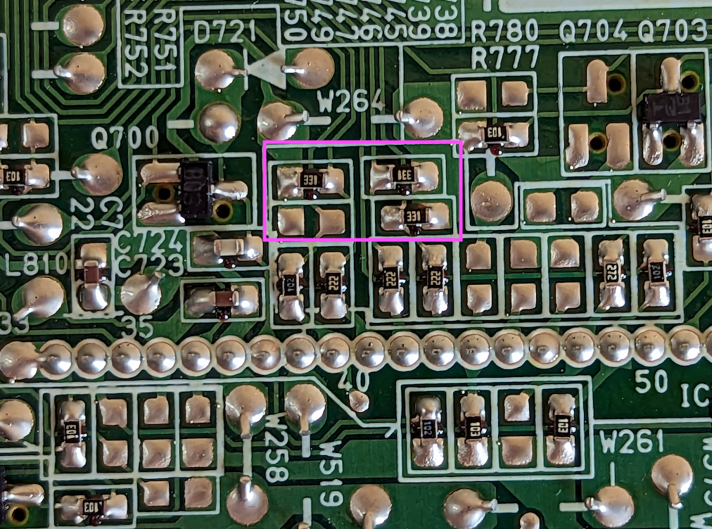
After removing the resistors 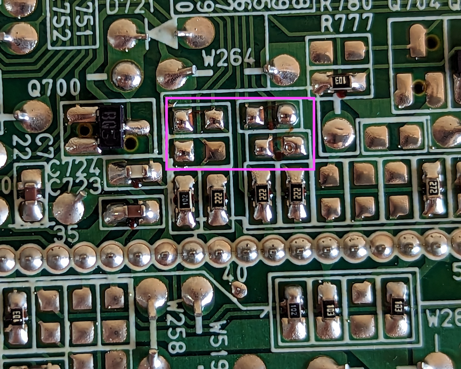
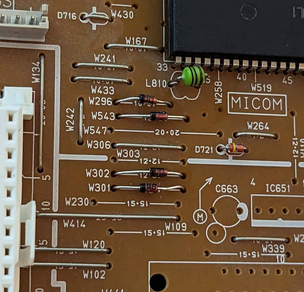
STEP 2: Replace jumper wires with diodes
Replace OSD jumper wires with inline 1N4148 diodes. These wires are:
- W296 (blanking)
- W543 (blue)
- W302 (red)
- W301 (green)
Make sure the cathode end is towards the jungle as shown.
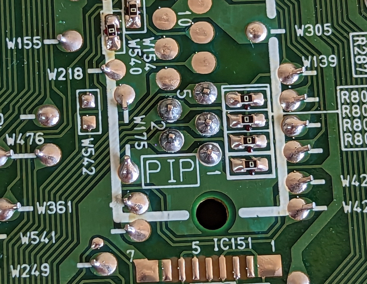
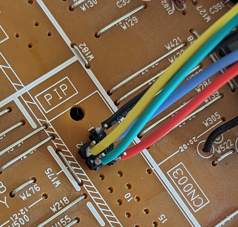
STEP 3: Utilize the PIP header to expose RGB, Blanking and GND
At the end of these OSD lines they will connect through the unpopulated PIP connector CN003 and then enter 0 Ohm resistors before traveling to the jungle. These holes for the PIP header are convenient, as we can use them to bring the signals up to the top of the board. Standard header pins (for arduinos, etc) will fit but it's a tight squeeze. This is the route I chose. Optionally add header pins to the PIP pins 1-5. They are as follows:
- 1: ground
- 2: blanking (yellow wire > brown if you are using the ribbon cable)
- 3: blue
- 4: green
- 5: red
Finally, solder wires (or use quick connectors, but I avoid these due to interference/noise) to these on the top of the board, make sure they have enough length to reach the case where you will mount your external connectors (SCART, etc).
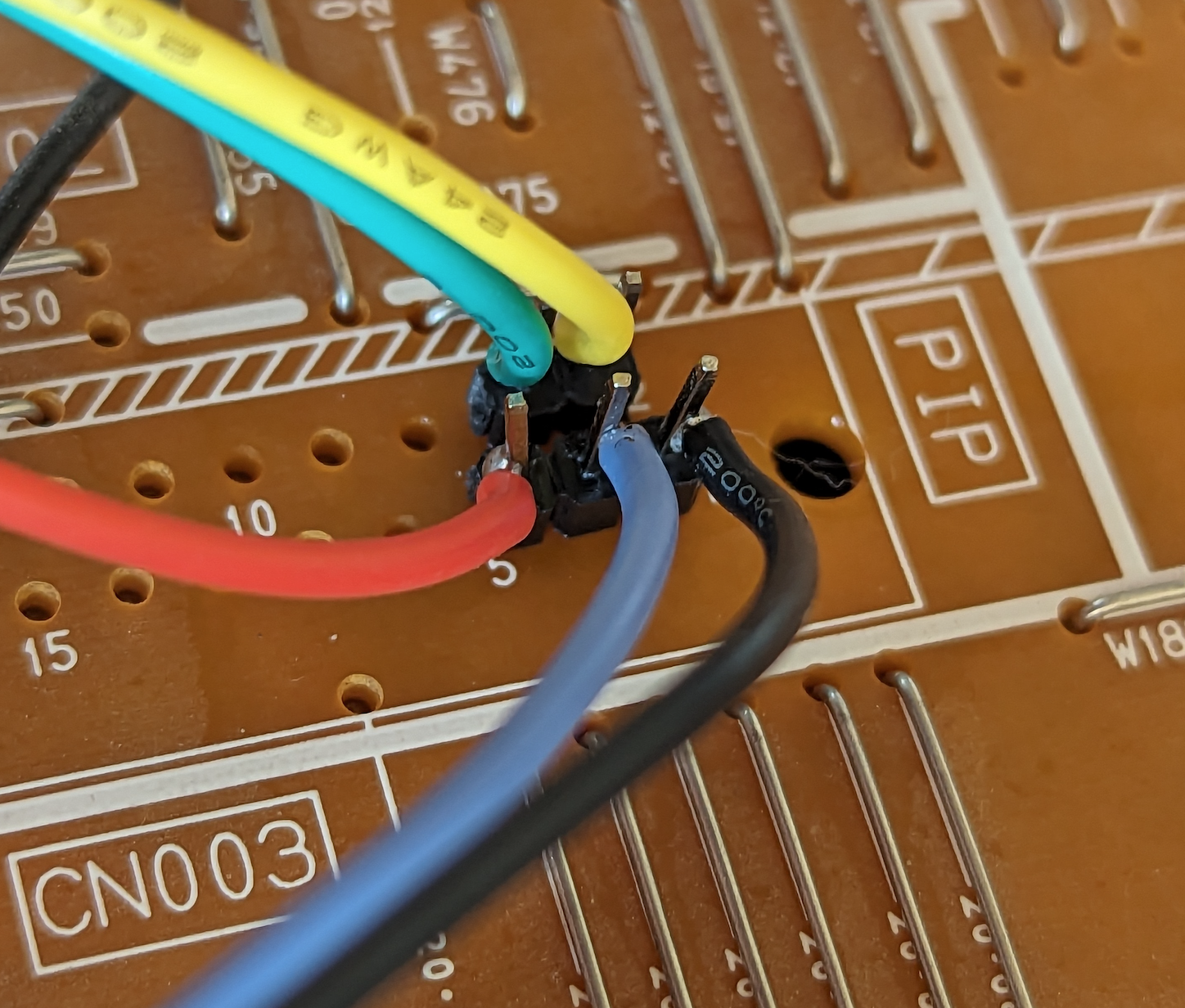
STEP 4: Audio
Attach the rest of the wires necessary for your connector. If you're using SCART, you'll need wires for audio left and right. Regardless of SCART/BNC, you'll also need to attach a wire to the Component Luma pin for sync. Solder them at the pins like so. Make sure you use the component and audio jacks for Video 2. (I forgot to take a pic of my green wire - see the schematic for where it should go though).
Audio wires 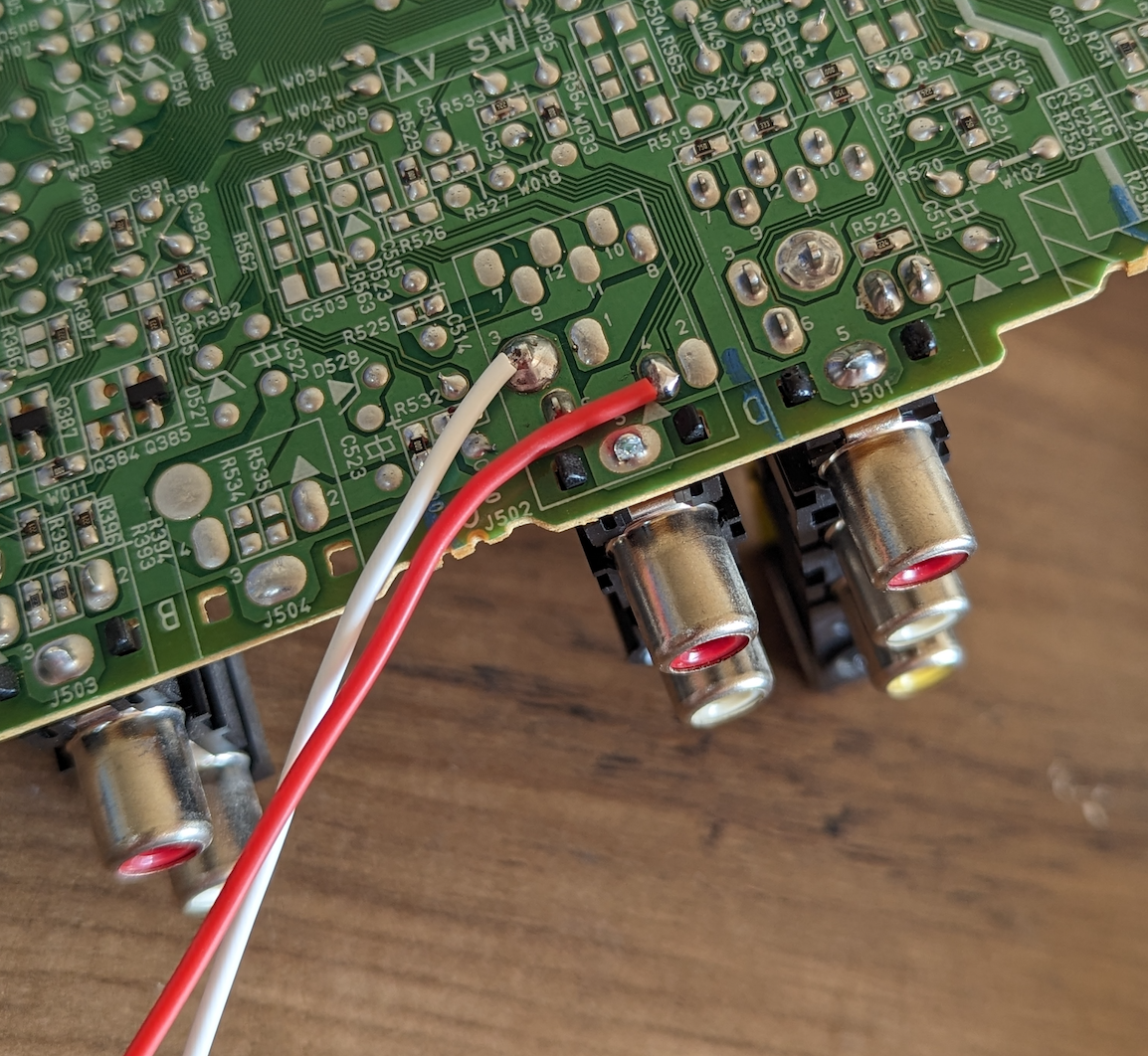
All wired up! 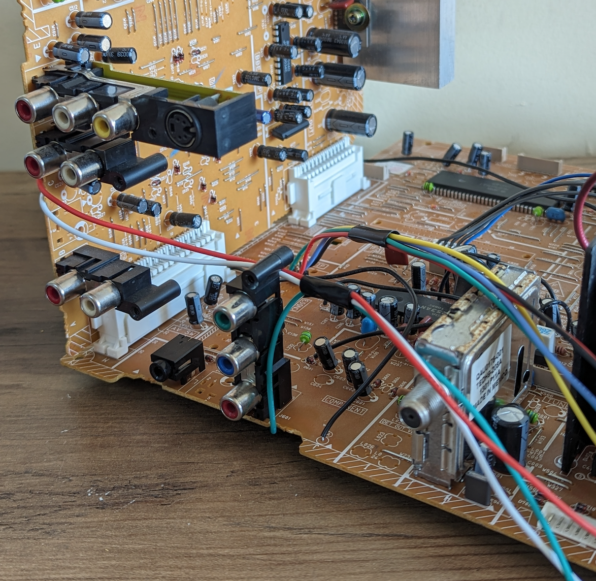
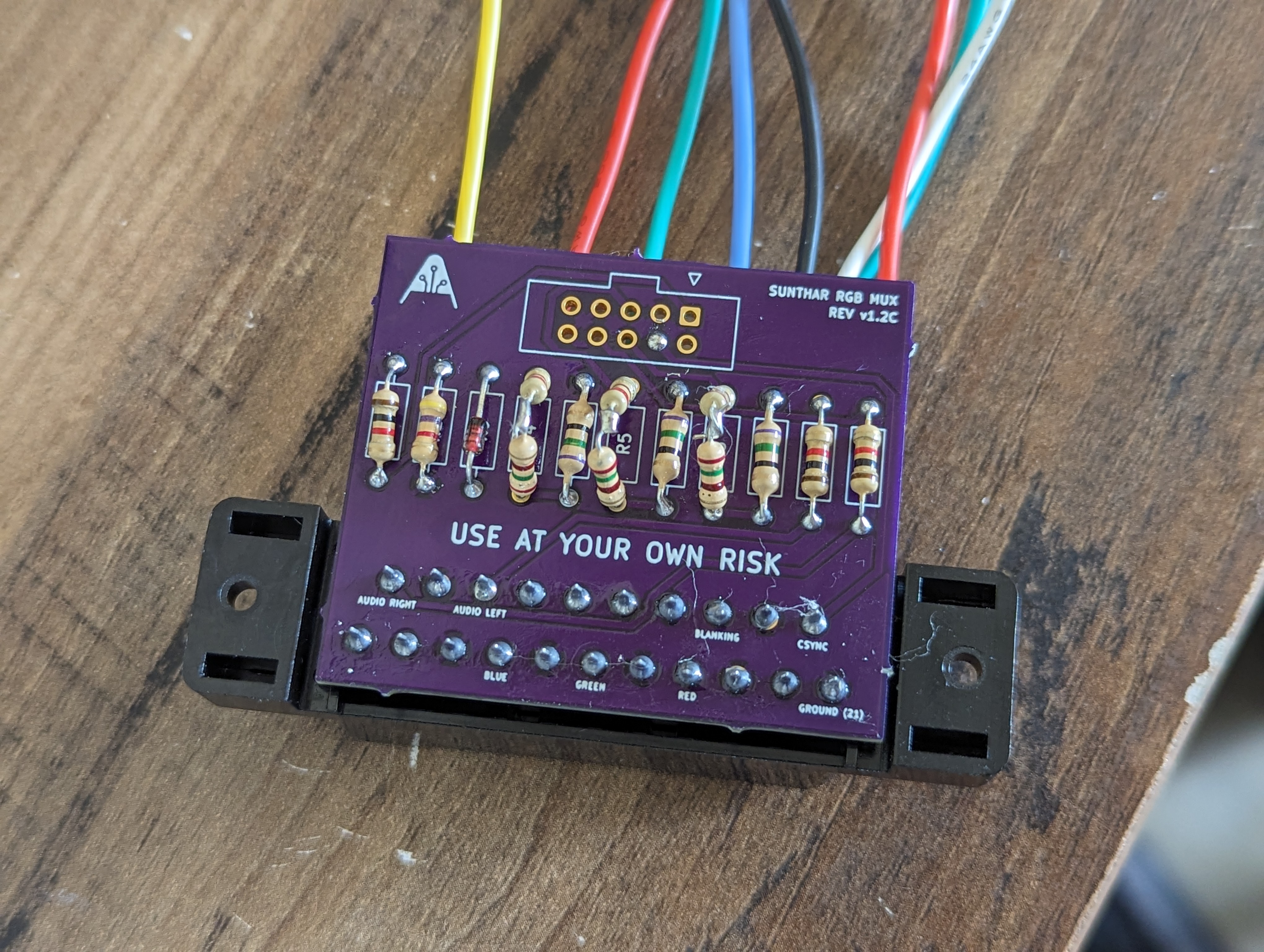
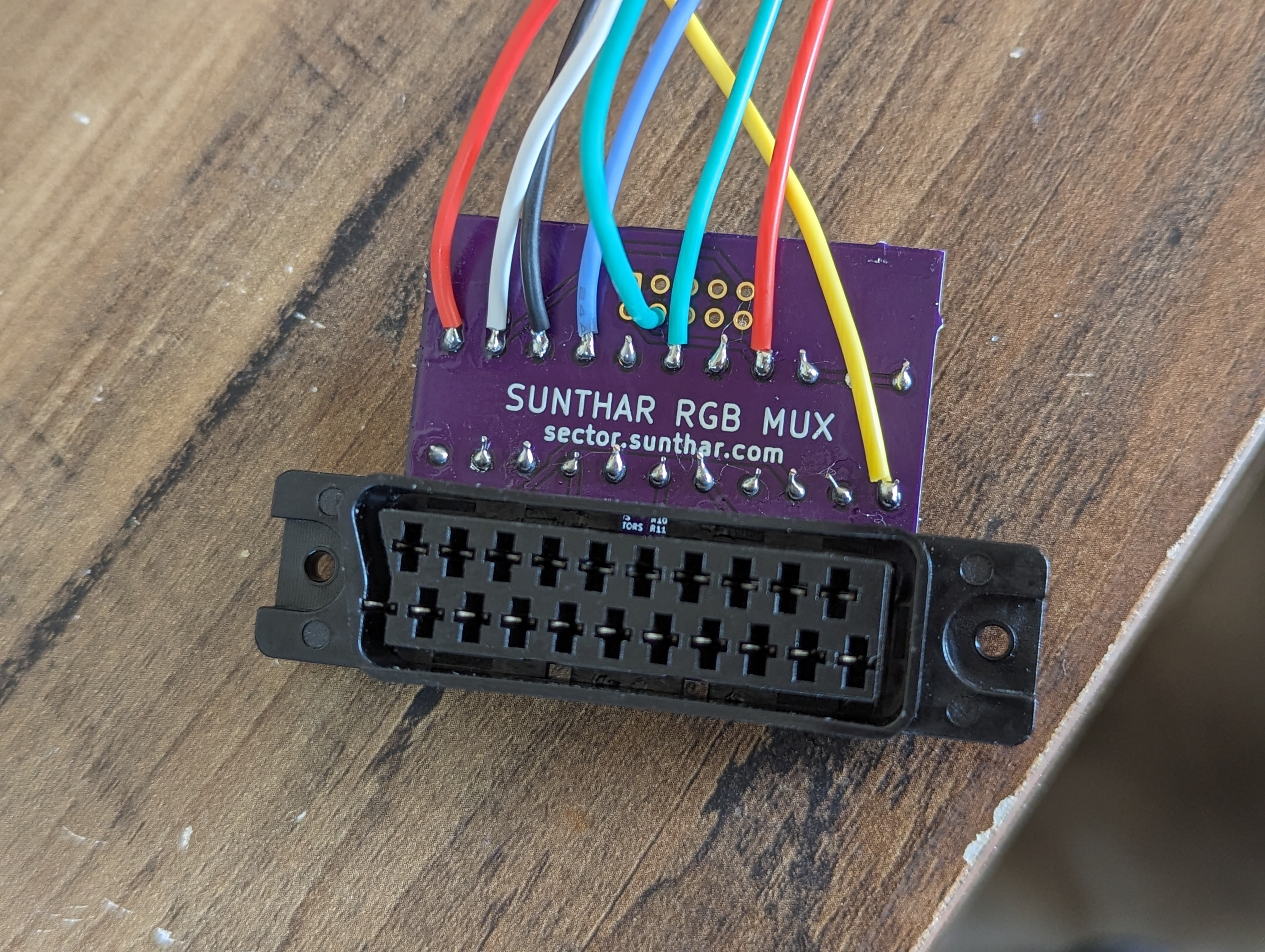
STEP 5: Build your mux board
This mod uses the RGB mux board. This is optional, but will make your mod easier and stable. You can also create the circuit presented in the schematics above without the board. Please also checkout the mux calculator to play with your own values.
| Component | Value |
|---|---|
| RGB/OSD inline resistor (chassis) | 2.2kΩ |
| Removed RGB/OSD resistor (chassis) | 330Ω |
| RGB inline diode method (chassis) | Yes |
| RGB termination (R1, R2, R3) | 220Ω |
| RGB inline (R4, R5, R6) | 390Ω |
| Audio LR (R7, R8) | 1kΩ |
| Diode (R9) | 1N4148 |
| Blanking Ground Resistor (R10) | 4.7kΩ |
| Blanking Resistor (R11) | 1kΩ |
Compatible mux boards: RGB MUX BOARD KIT 1.4C, RGB MUX BOARD KIT 1.4B
RGB mini mux board was used on this D-Series. The modification presented here does not utilize the benefits of the 10-pin DIN connector for convenient disconnection. However, it is strongly advisable to take this into account for your mod, as it would greatly enhance future serviceability.
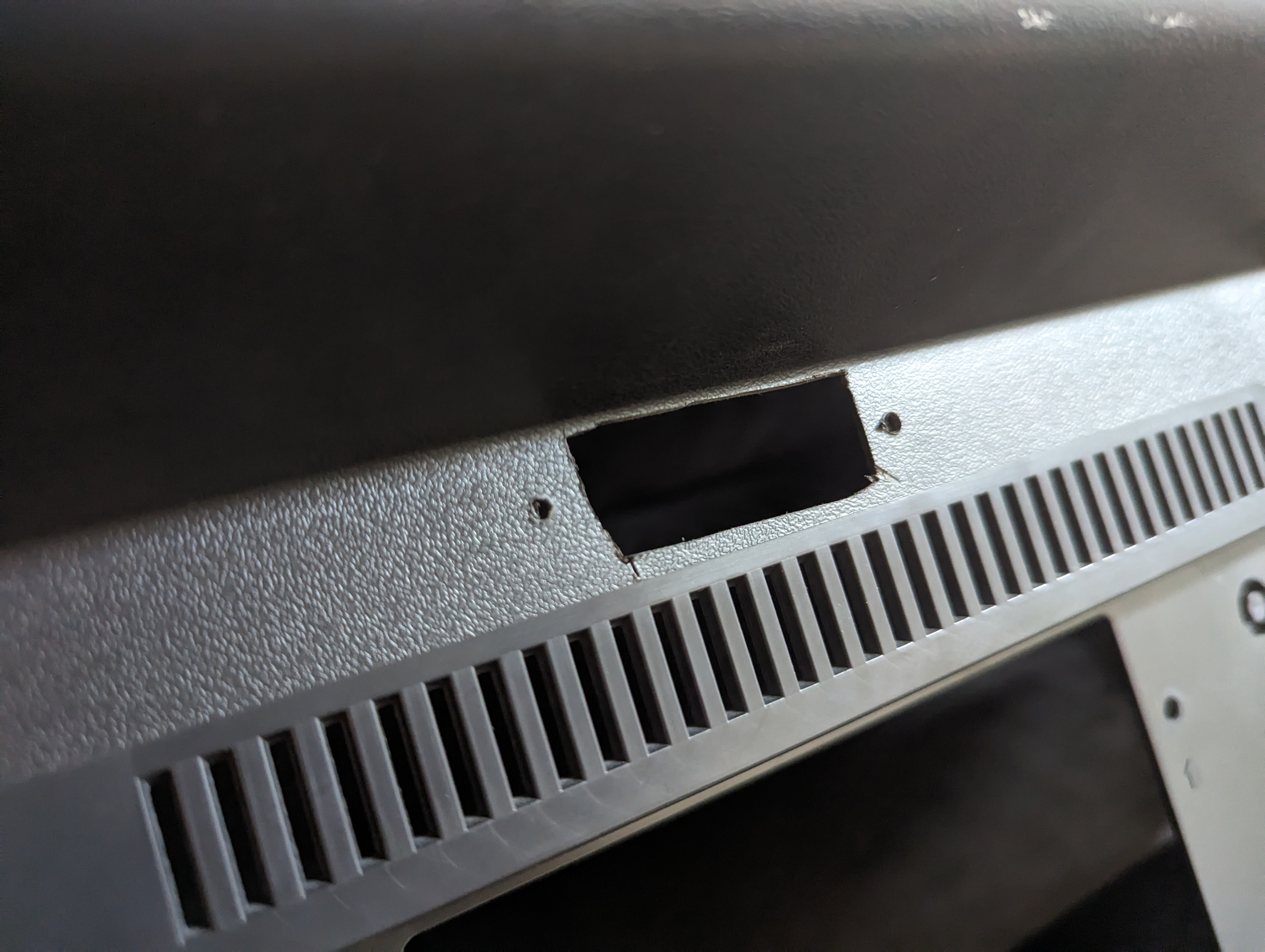
STEP 6: Attach the female SCART connector to TV
Creating a SCART cutout and mounting it is an art. There is a dedicated section for it. How to create and mount a SCART female plug?
Cut a hole in the back case for the SCART connector. Depending on if you're using a mux board, directly wired to SCART, or even using BNC or RCA, you should have plenty of options of locations. I chose above the input panel.
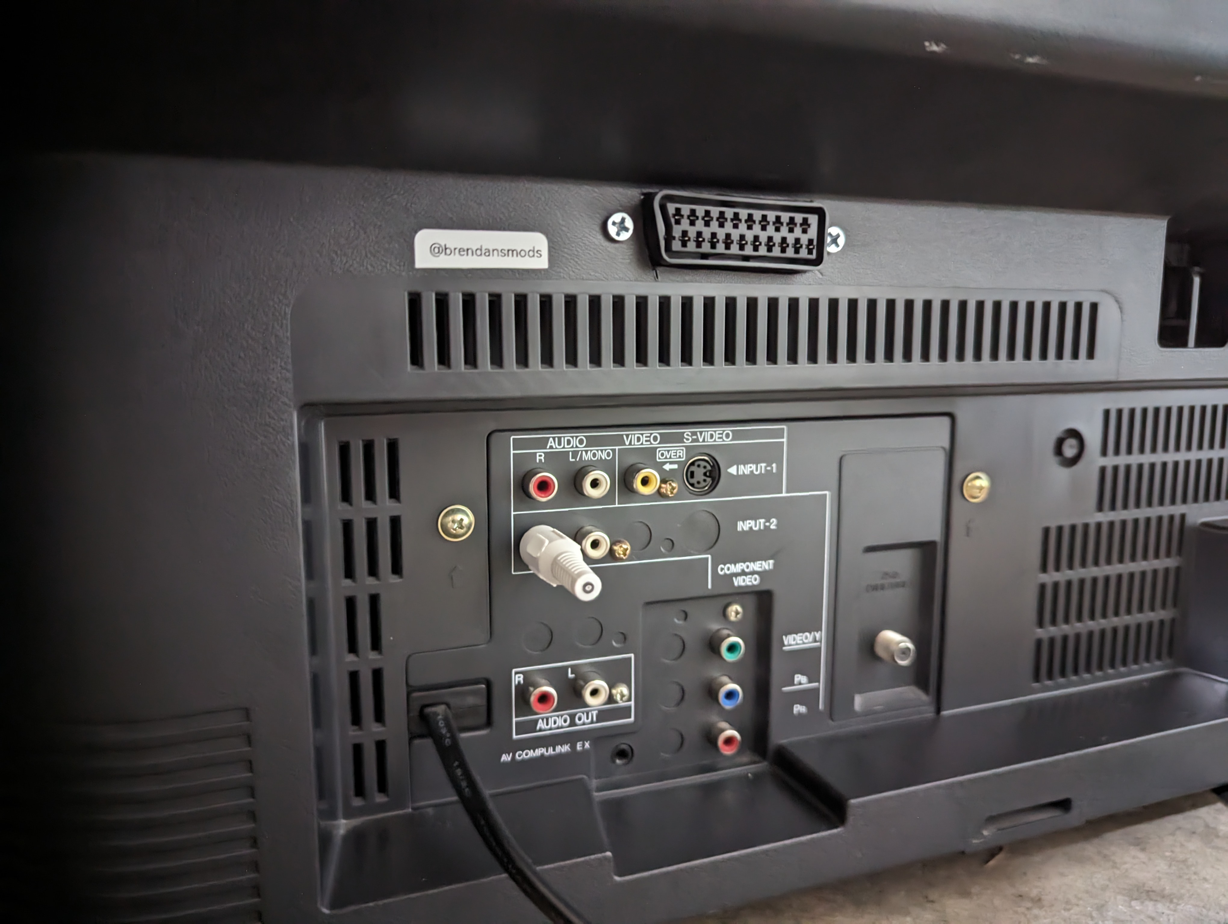
Insert a cut RCA jack into the Right audio channel in order to signal to the set to use stereo audio over SCART. If you omit this step, your audio will be mono. (Don't get confused at the fact my RCA is white. It's just what I had. Insert it into the red (Right audio) jack).
Service Menu
- Press the
SLEEP TIMERkey and set theSLEEP TIMERfor0 MIN - While the
SLEEP TIMERis displaying on the CRT, do the below - Immediately press the
DISPLAYkey and theVIDEO STATUSkey of the remote control unit at the same time. - Then enter the
SERVICE MENUscreen shown in figure.
Pictures
Mux overlay
RGB Overlay 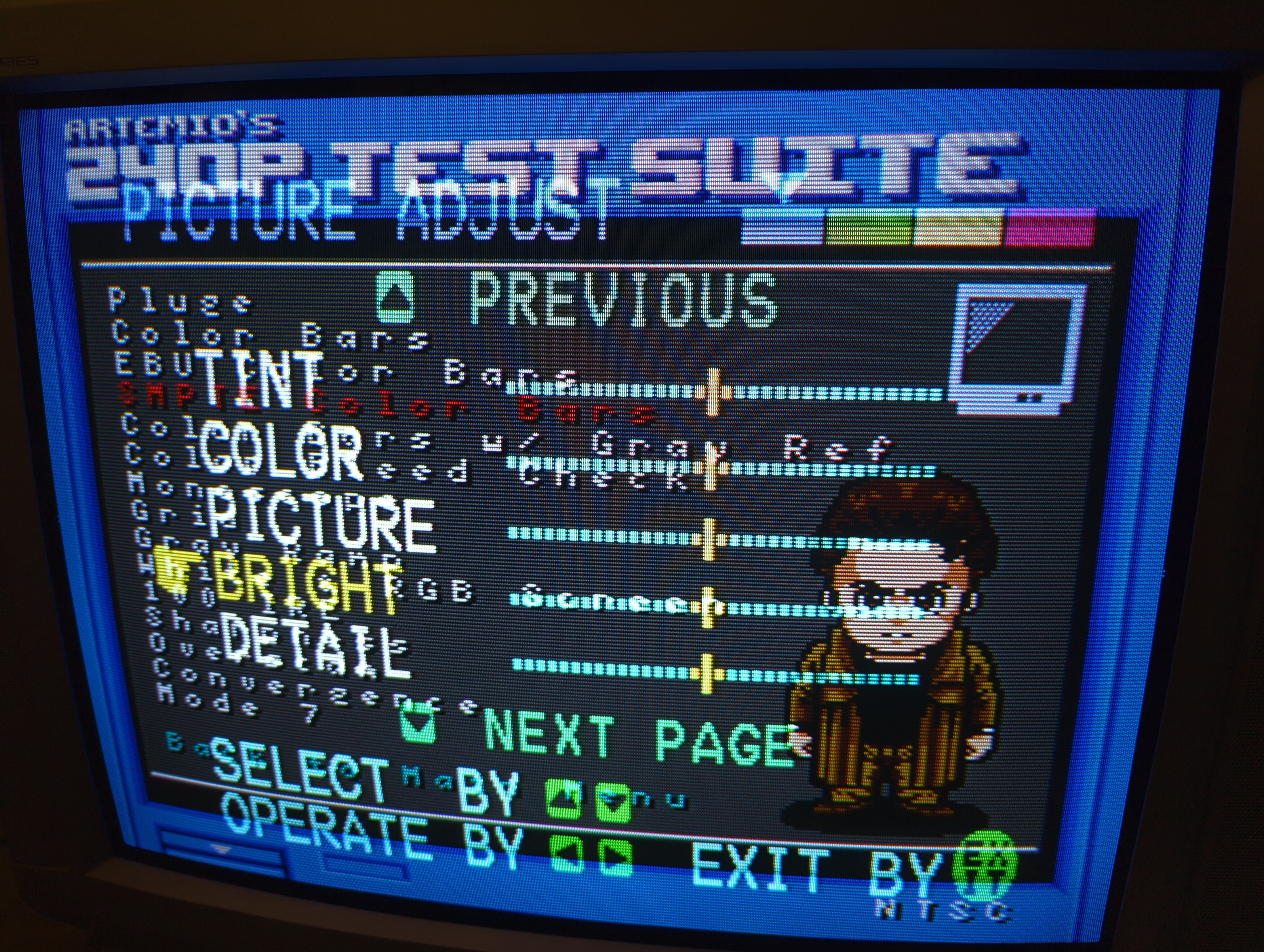
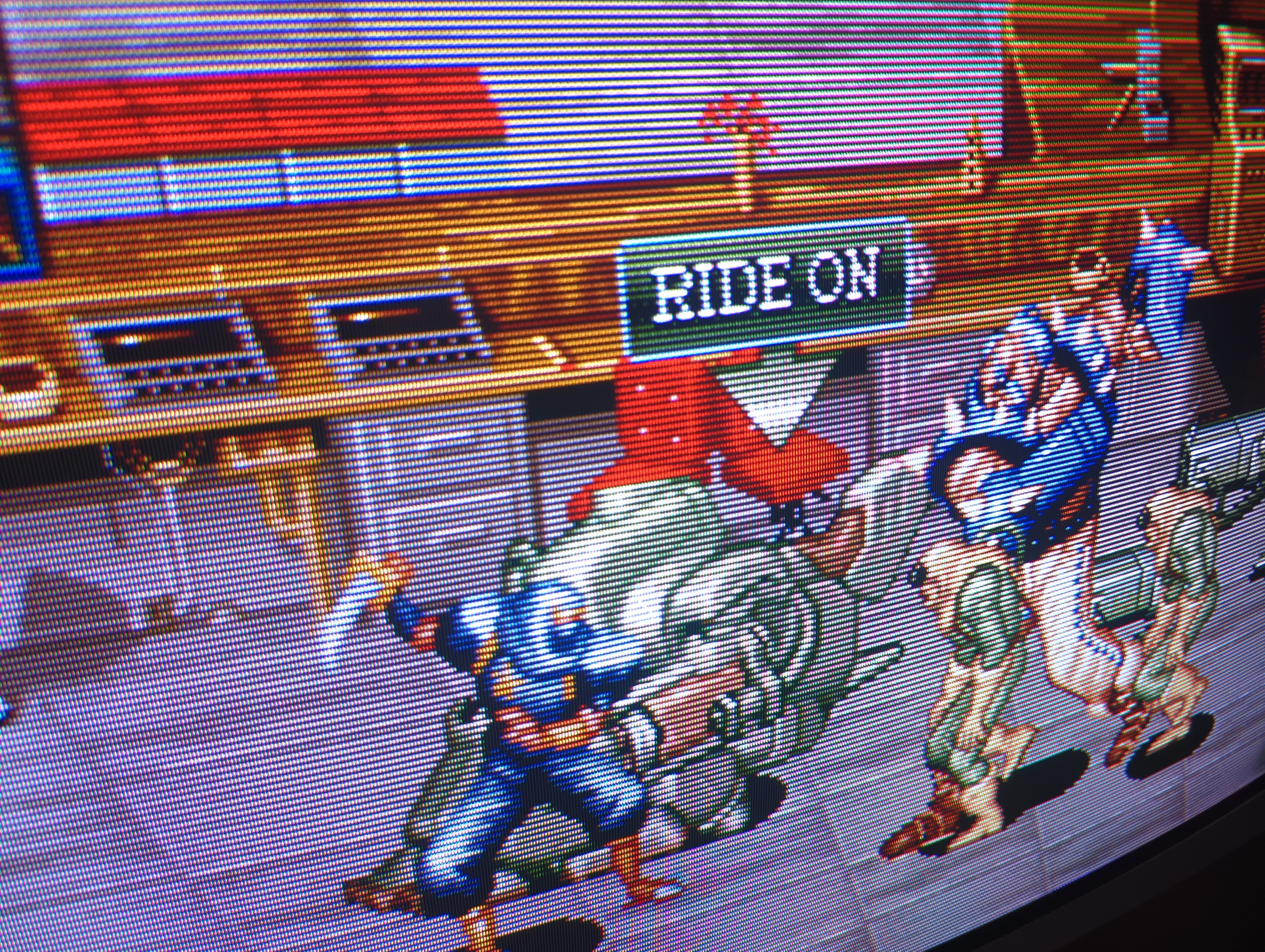
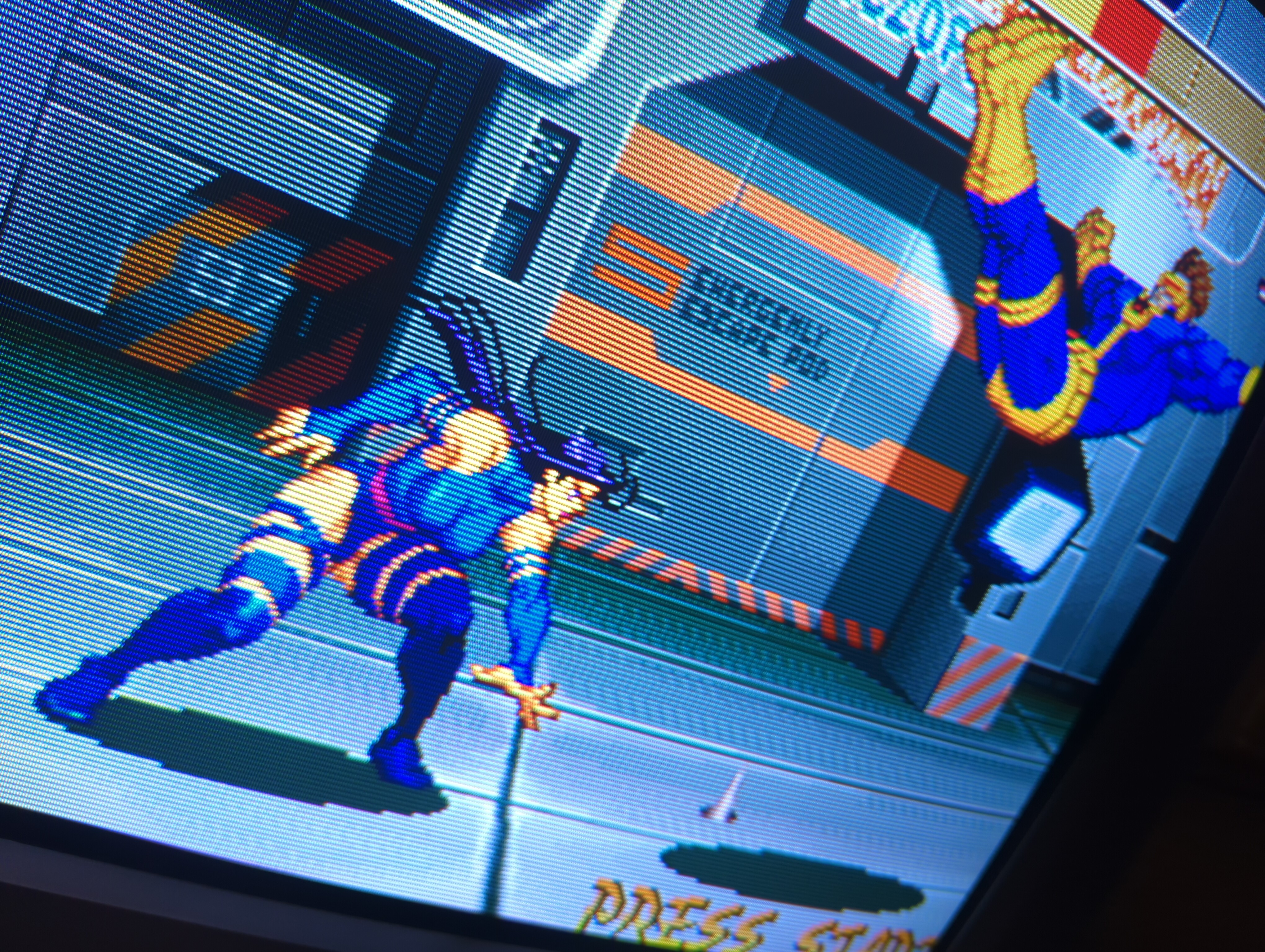
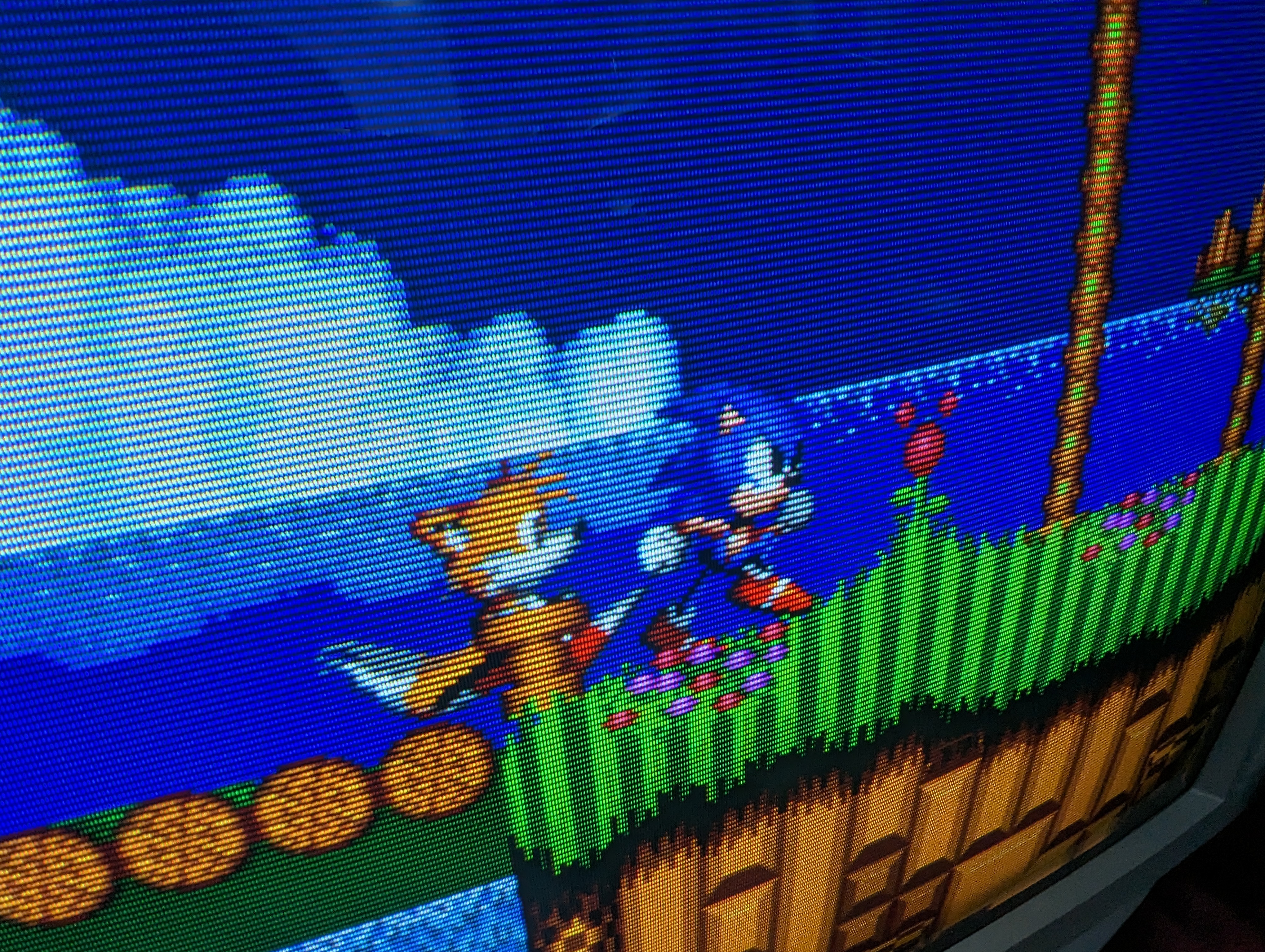
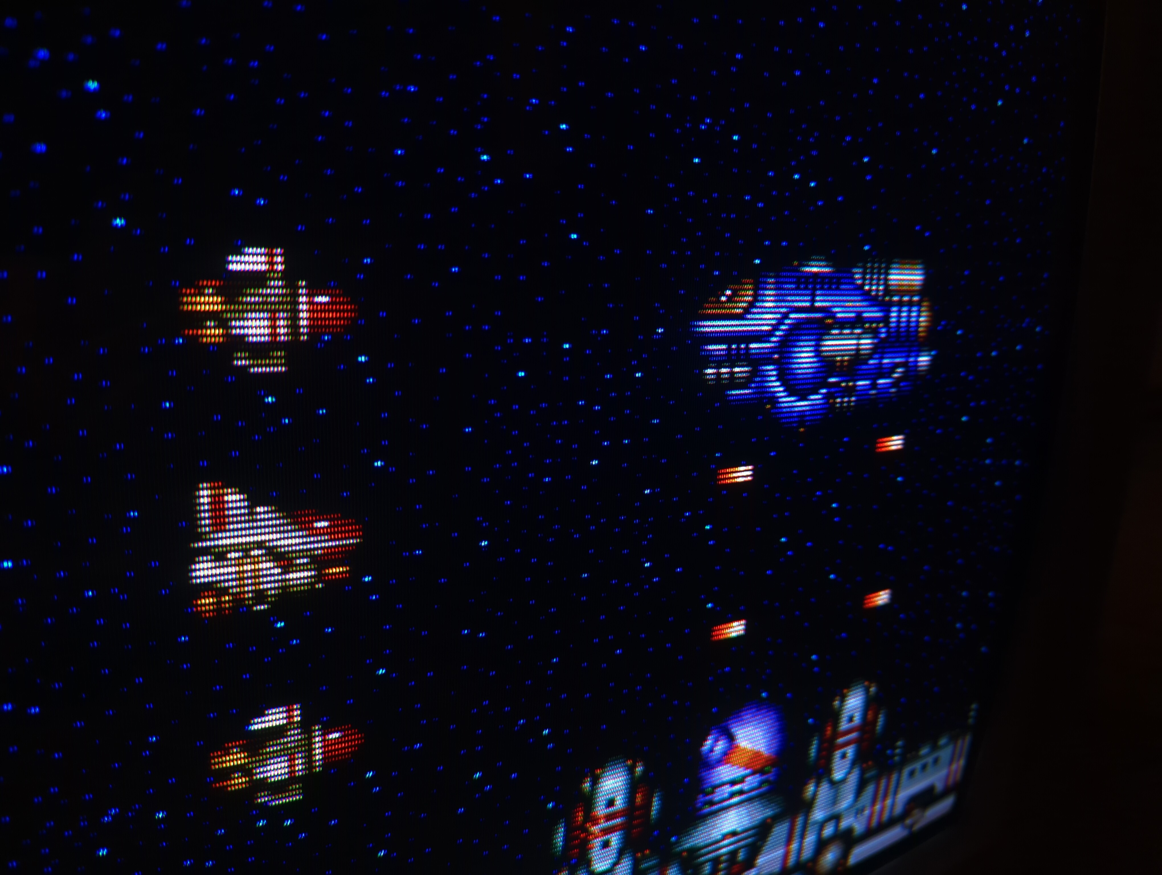
Games
Patterns
240p pattern - Monoscope 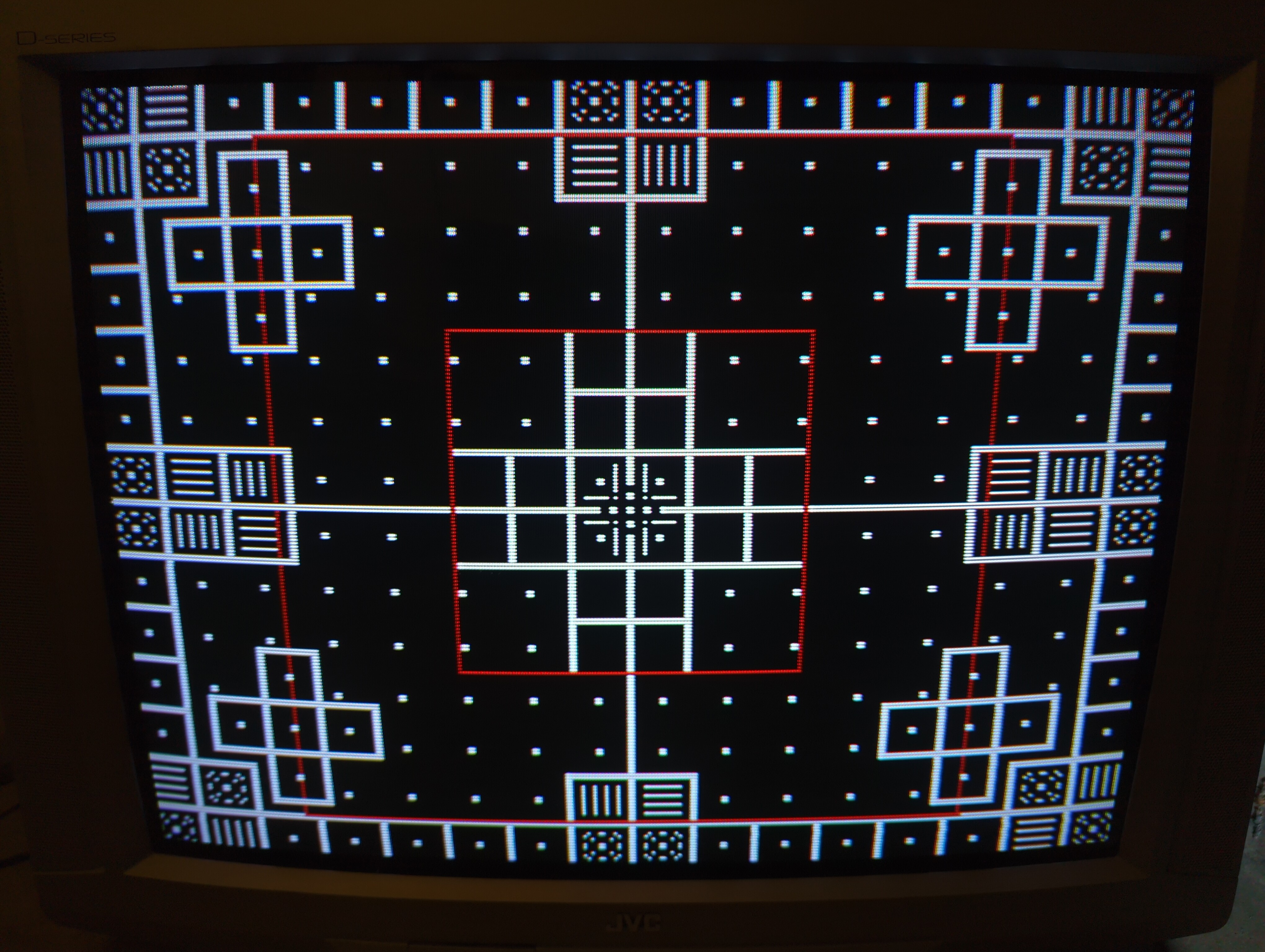
240p pattern - Color bars 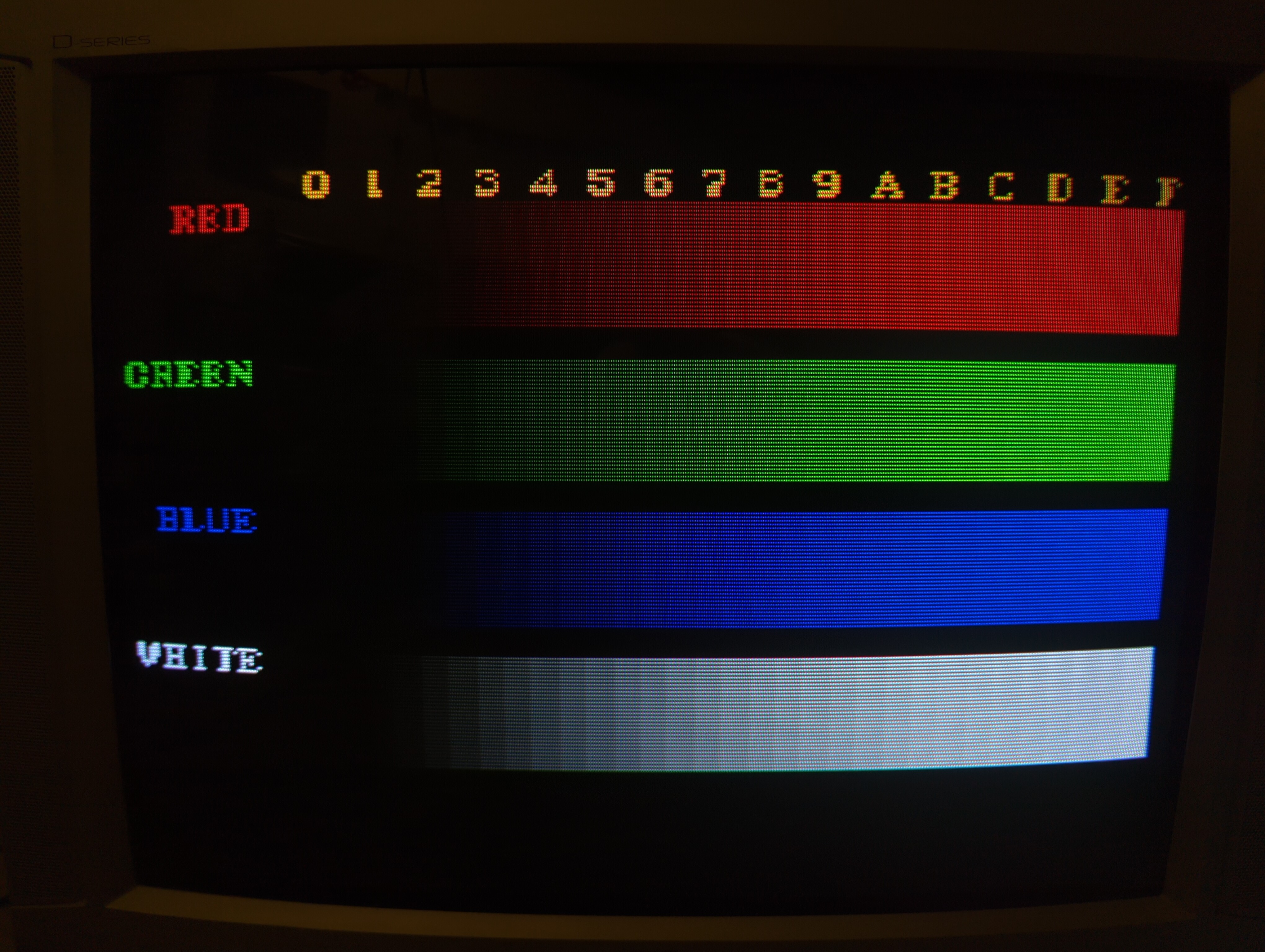
240p pattern - SMPTE 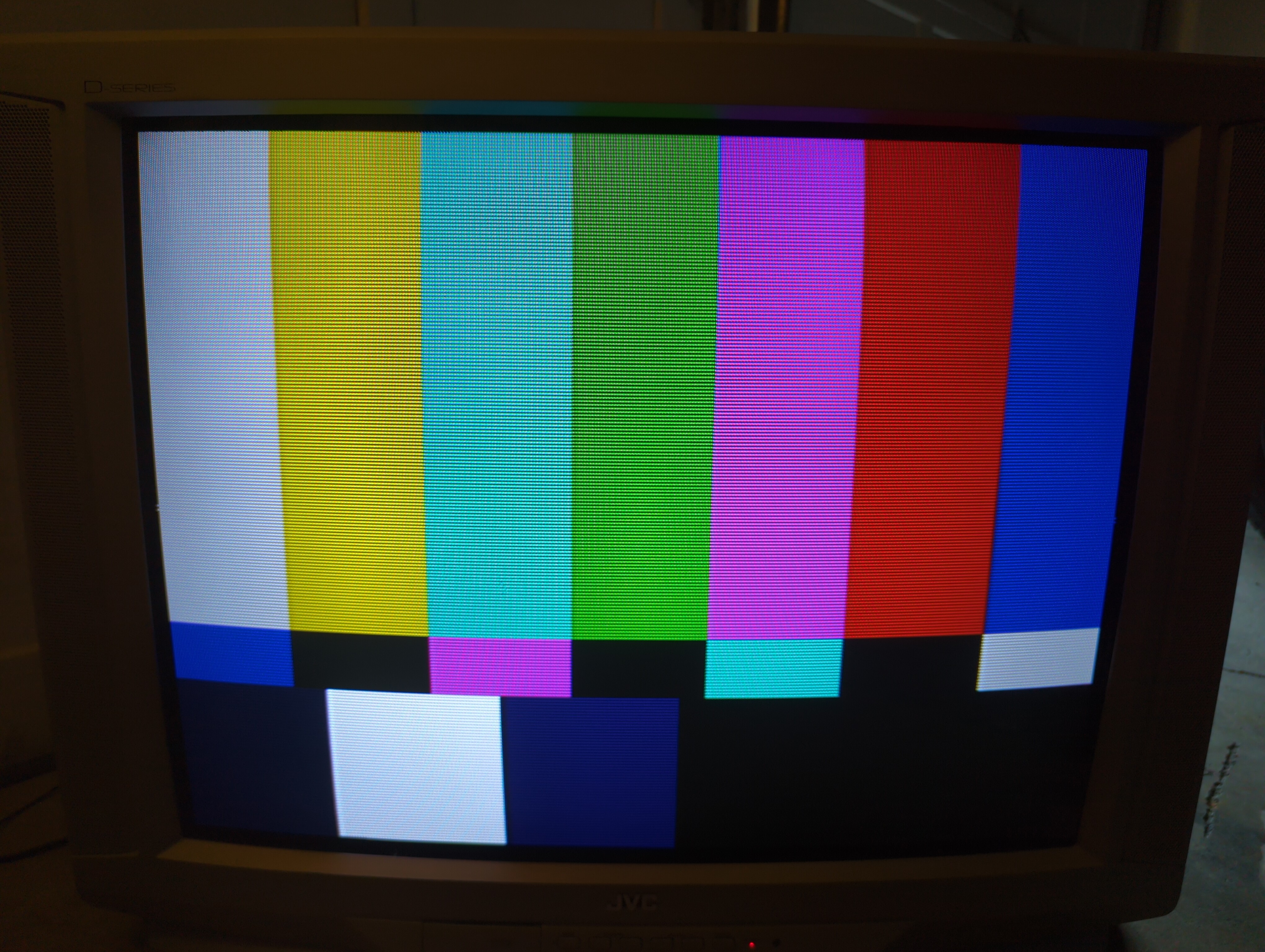
Pictures
Reference Photos