RGB Tuner
RGB Tuner
If you want the best possible RGB output from your CRT and don't want to try various resistor values and build blanking divider circuits, then this RGB tuner is for you. I mean who wants to sweat over an RGB mod? 😃
Some CRTs don't give the best possible RGB output with the calculated values. With some chroma chips R, G, B inputs only go through cutoff adjustments. This is where it is nice to have an apparatus to fine tune the injected RGB signal.
Also, it's nice to have a device to test various RGB resistance values, especially if the chroma chip blanks at weird voltages.(i.e. 2.5V).
How does it work?
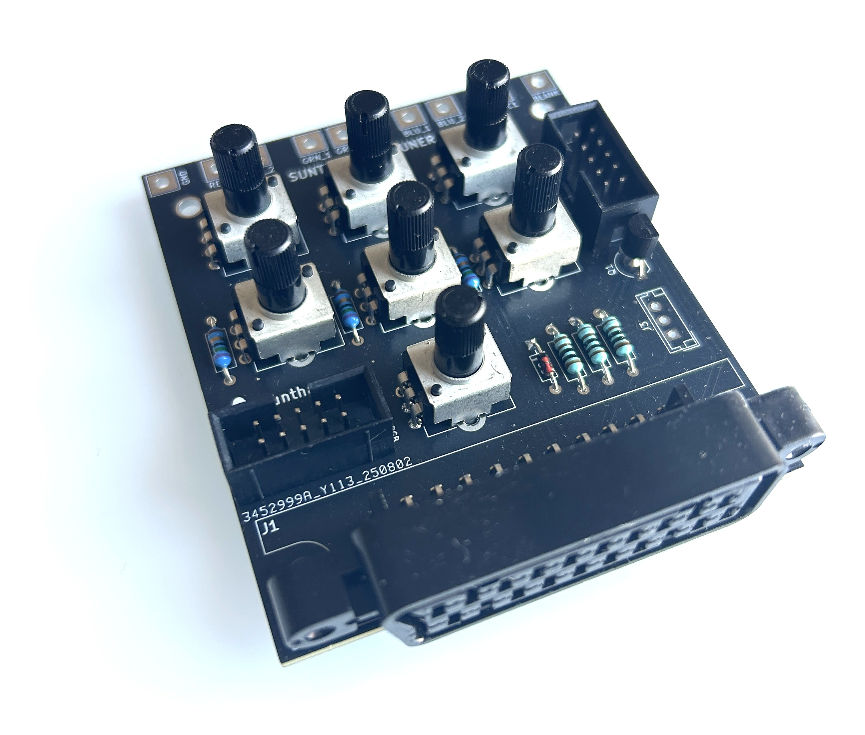
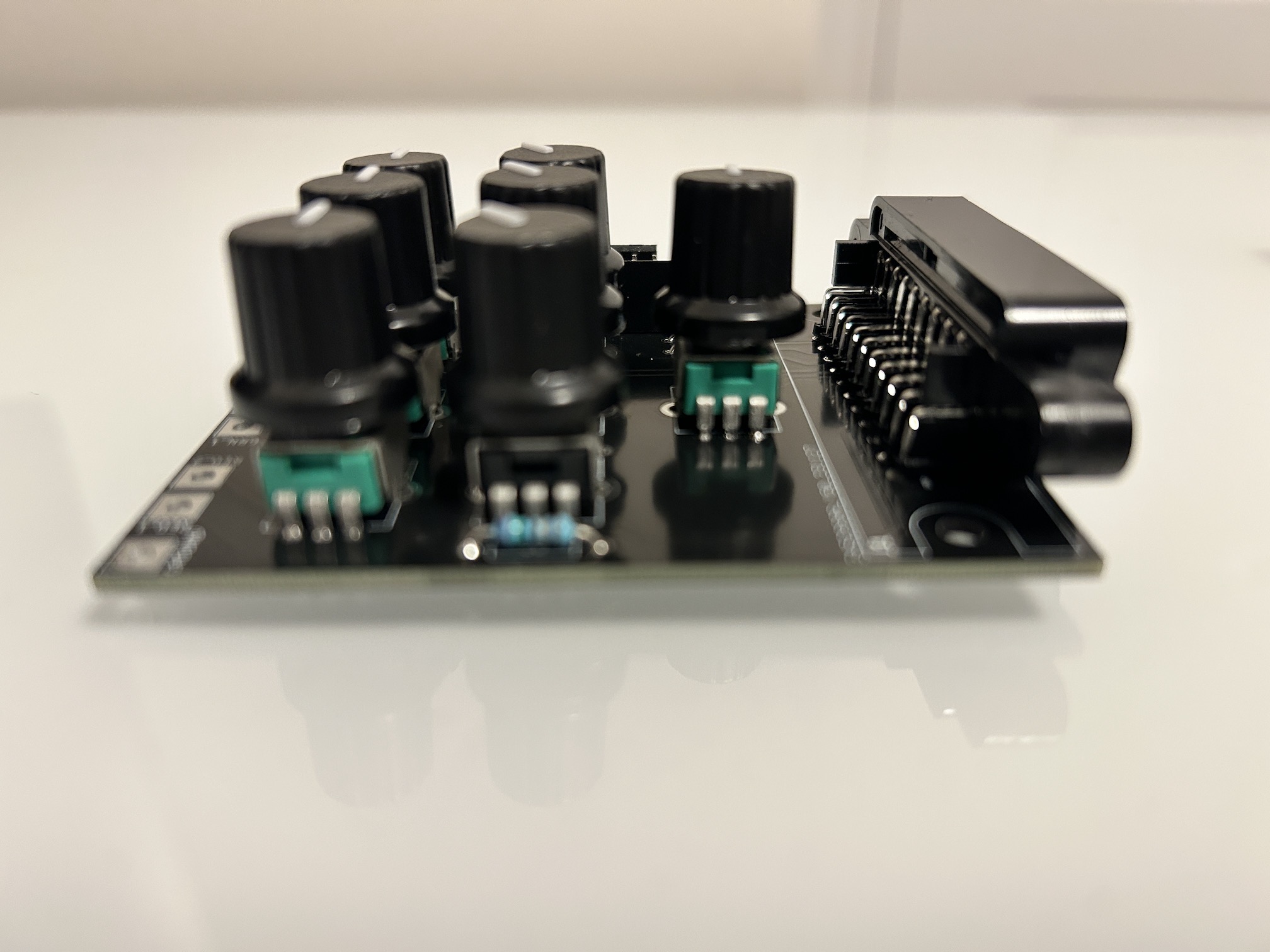
It's fairly simple. There are 7 adjustable pots on the device.
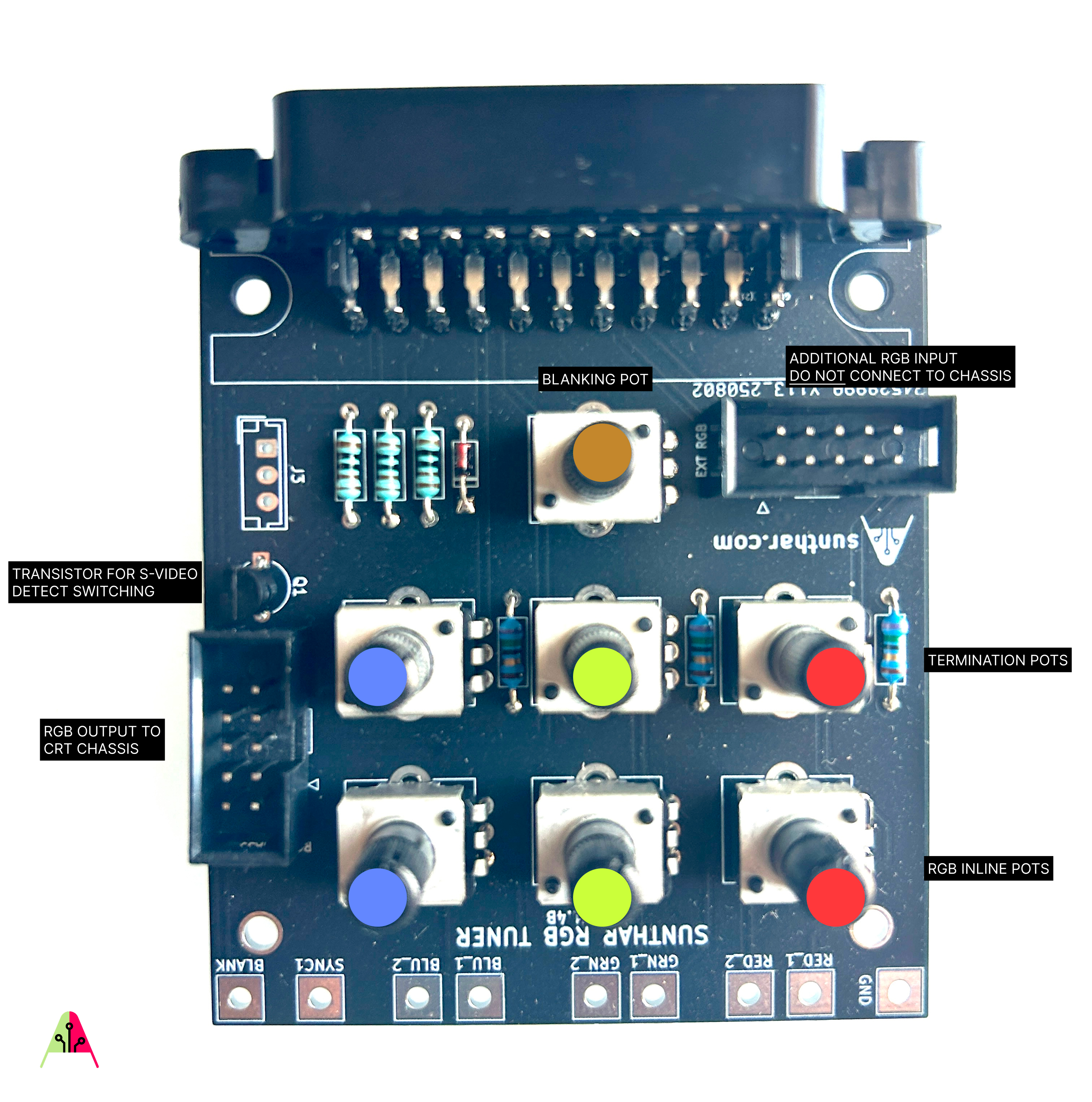
If you look at the above image, there are:
- 3 pots to adjust the RGB termination resistance values (75Ω to 1 kΩ)
- 3 pots to adjust the RGB inline resistance values (75Ω to 10 kΩ)
- 1 pot to adjust the blanking resistor value (this allows you to vary the voltage supplied to the CRT, up to 5 V sourced from SCART pin 16)
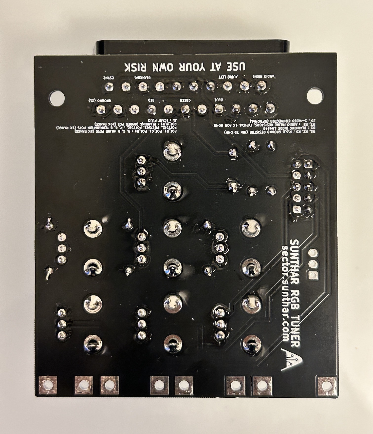
There are pads around the board that act as test points. This is a great way to measure and set the resistance of the pots and the voltage delivered through the ribbon cable.
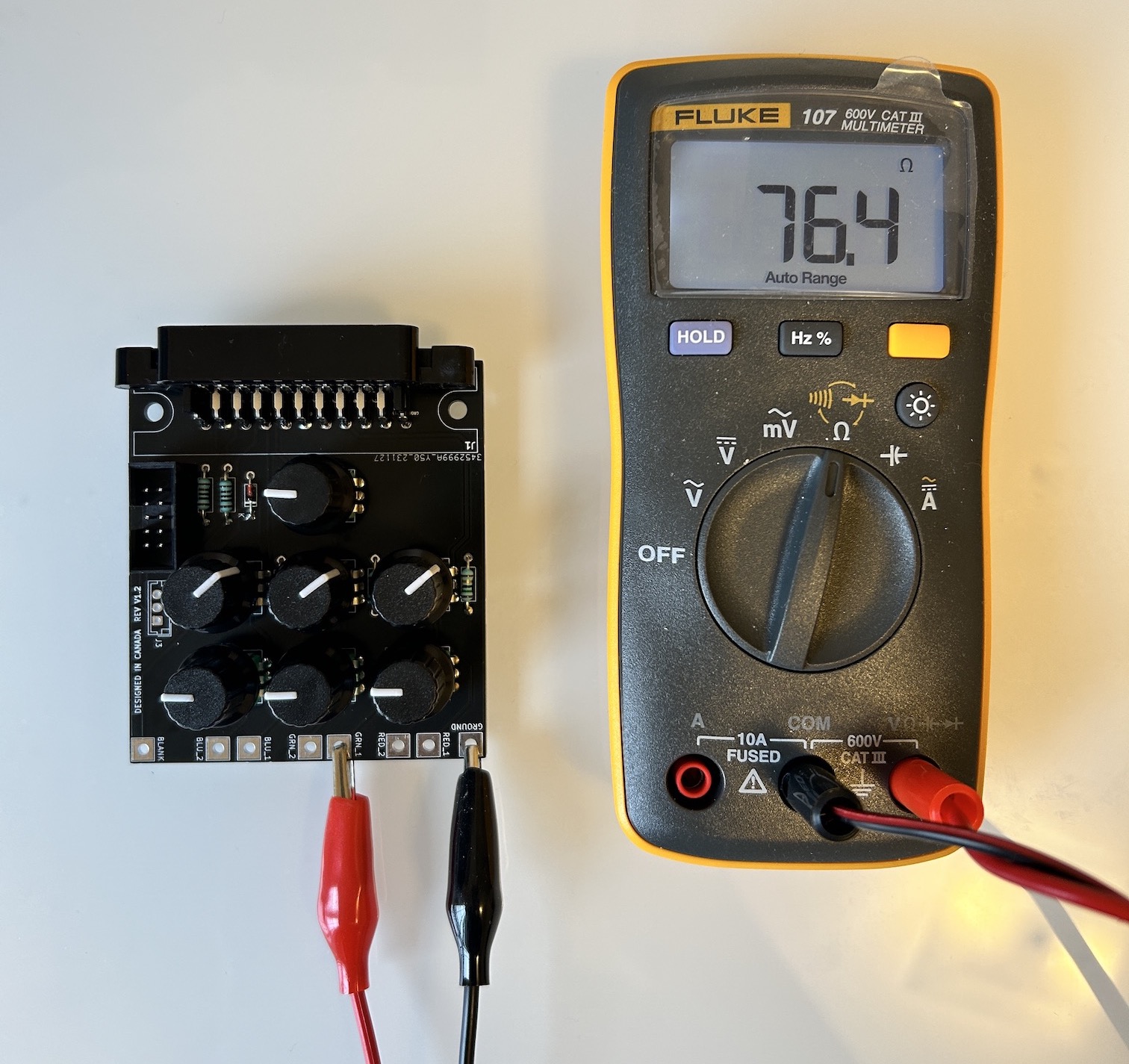
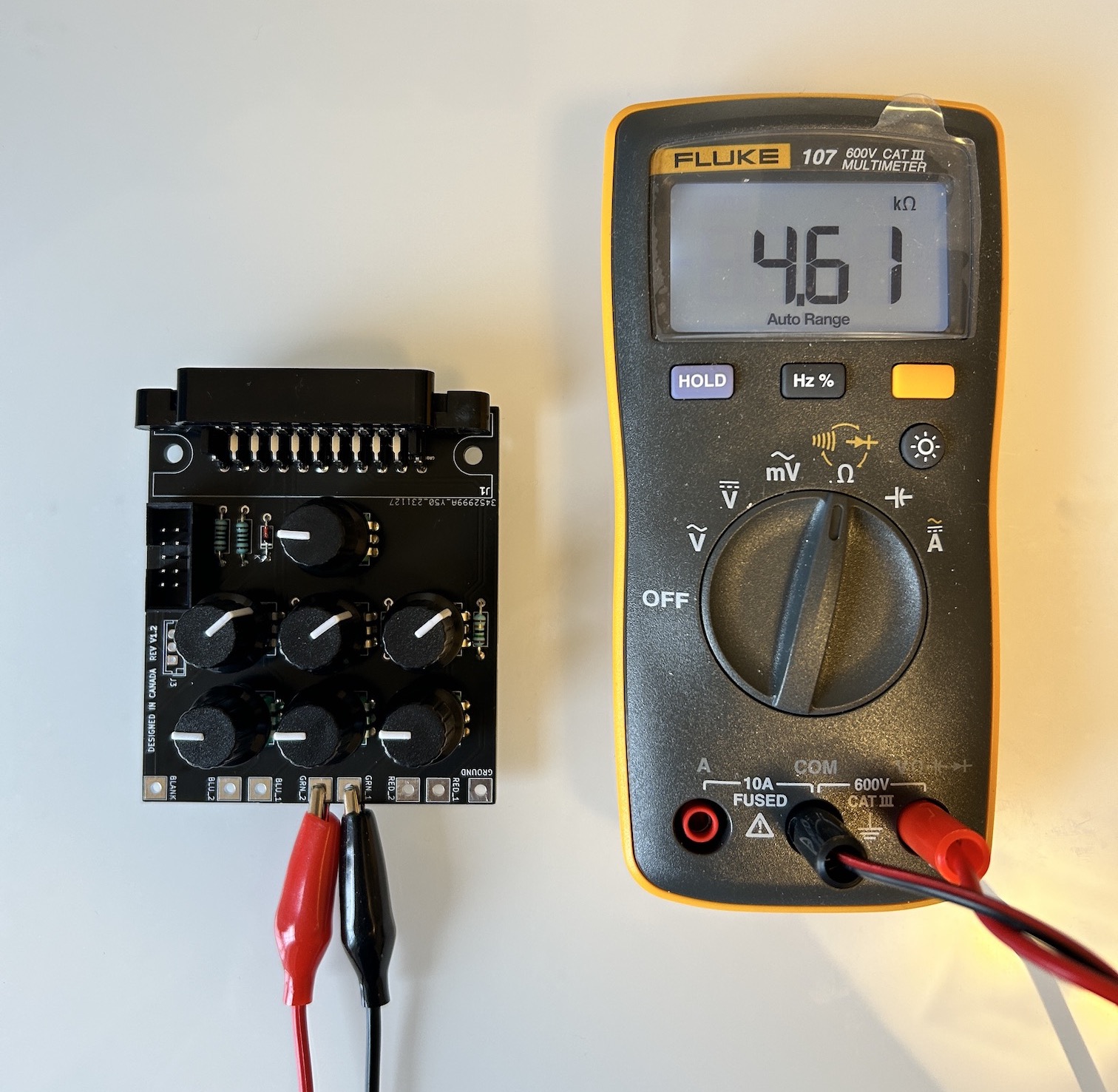
Tuning the termination resistance
 Picture from v1.2 board. Idea is the same with 1.4b board
For termination resistance, the minimum value is fixed at 75Ω using a resistor. You can adjust the termination resistance from 75Ω up to 1000Ω. While most mods would utilize 75Ω termination resistance, there are some RGB mods that will look better with 180Ω to 200Ω termination resistance (Example: Samsung TXH 1973).
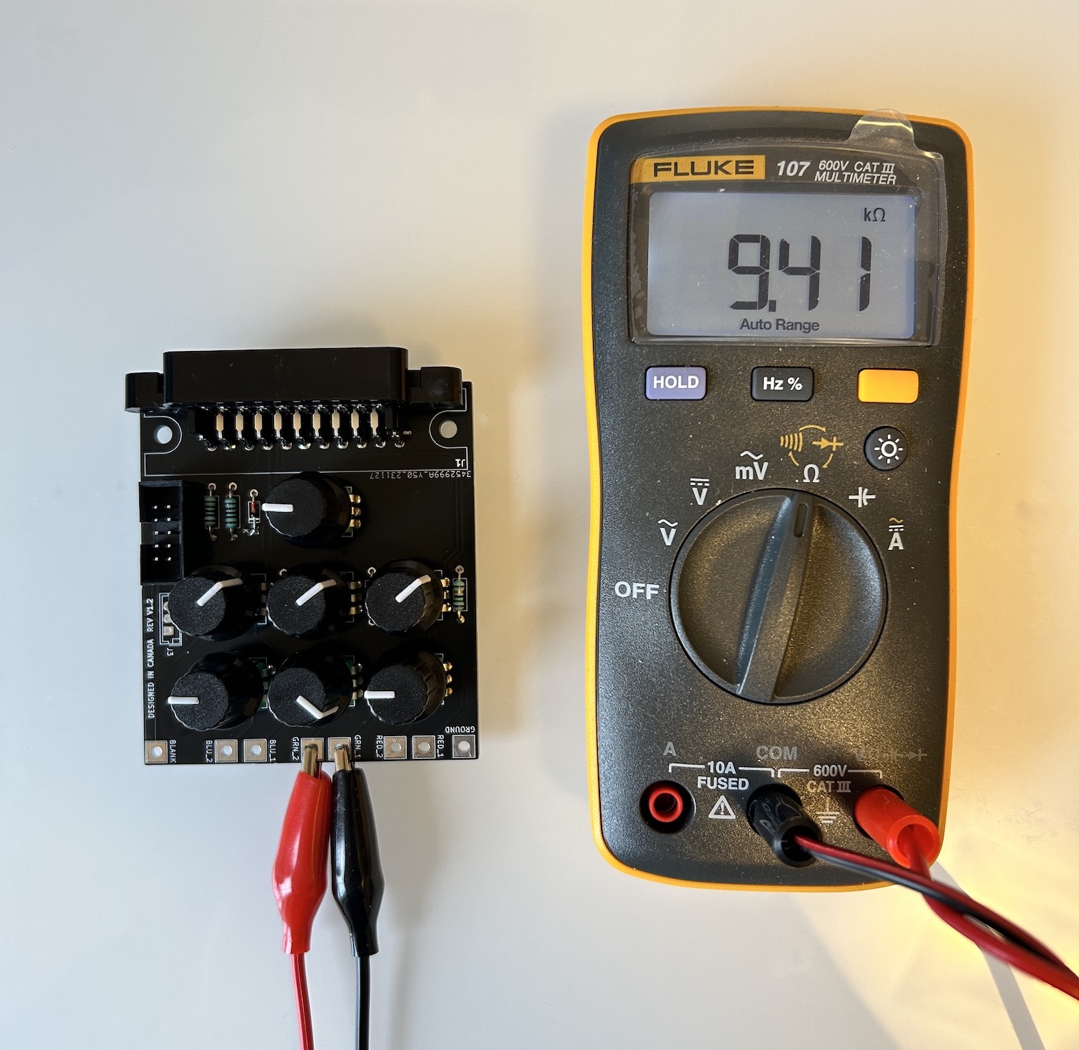
Tuning the RGB inline resistance
 Example: Green pot is mid way reading ~5kΩ
For the RGB inline resistance values, you can adjust it from (0Ω to 10 kΩ). Adjustments are going to be really fine within this range.
 Example: Green pot is fully turned in one direction reading ~10kΩ
Tuning the blanking voltage
![]() Example: Blanking pot is midway through, delivering a blanking voltage of 2.5V (5V/2) - 0.7V
Example: Blanking pot is midway through, delivering a blanking voltage of 2.5V (5V/2) - 0.7V
Blanking pot is setup as a voltage divider. While we are measuring the resistance here, we should really be measuring the voltage when connected to a SCART source. Since the divided voltage is then fed via a diode to the CRT, 0.7V should be subtracted. You can deliver 4.3V by turning blanking to the minimal ohm reading.
![]() Example: Blanking pot is turned to deliver 4.3V (5V - 0.7V)
Example: Blanking pot is turned to deliver 4.3V (5V - 0.7V)
Limitations
This board doesn't have an option to include in-line capacitors. For example, in some CRTs you would need 3x 0.1uF caps or 3x 0.47uF ceramic caps to be included inline before feeding the RGB signal to the chroma chip. However, for mods that require these caps (i.e. BA-1), you really have nothing to tune.
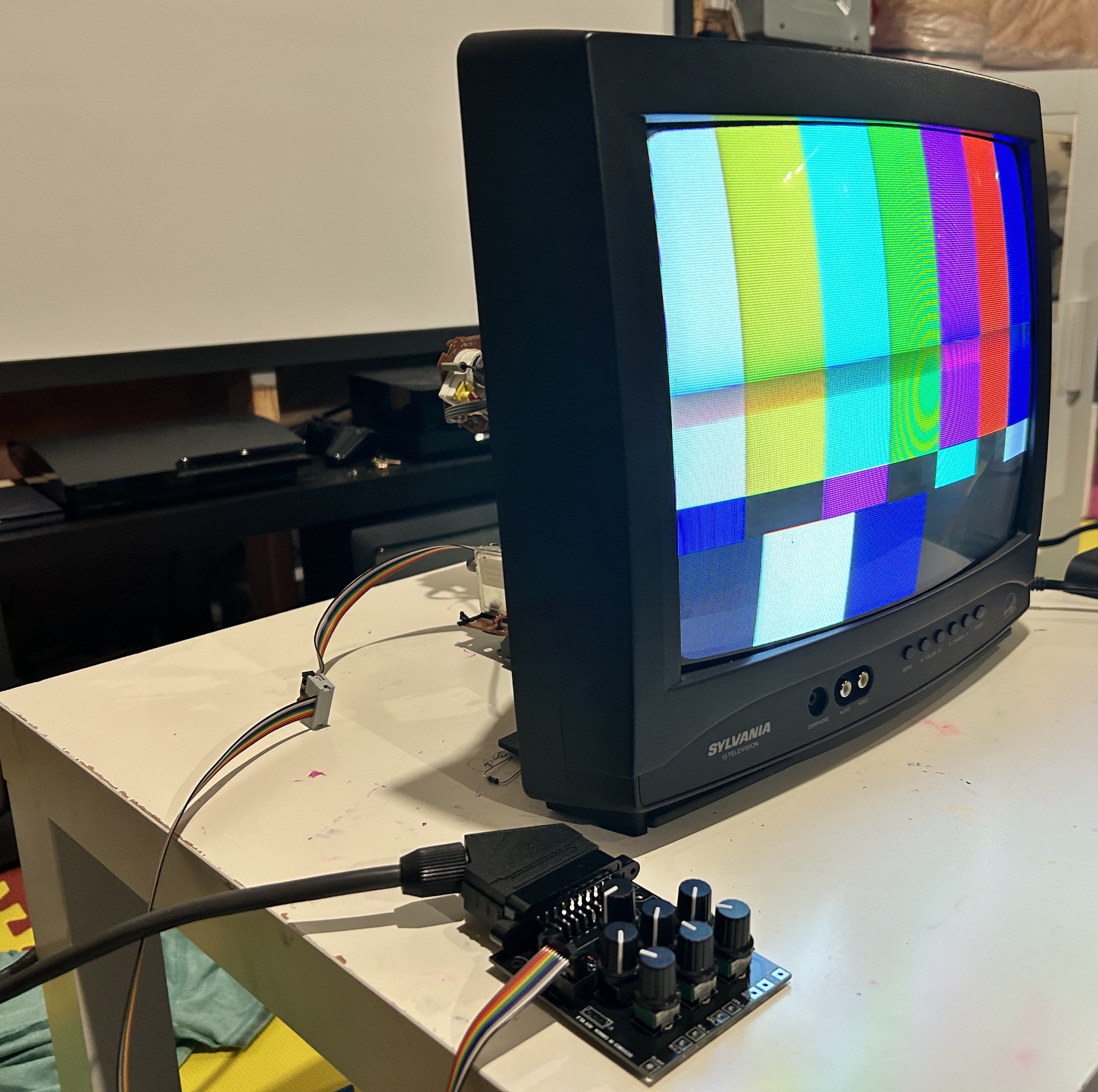
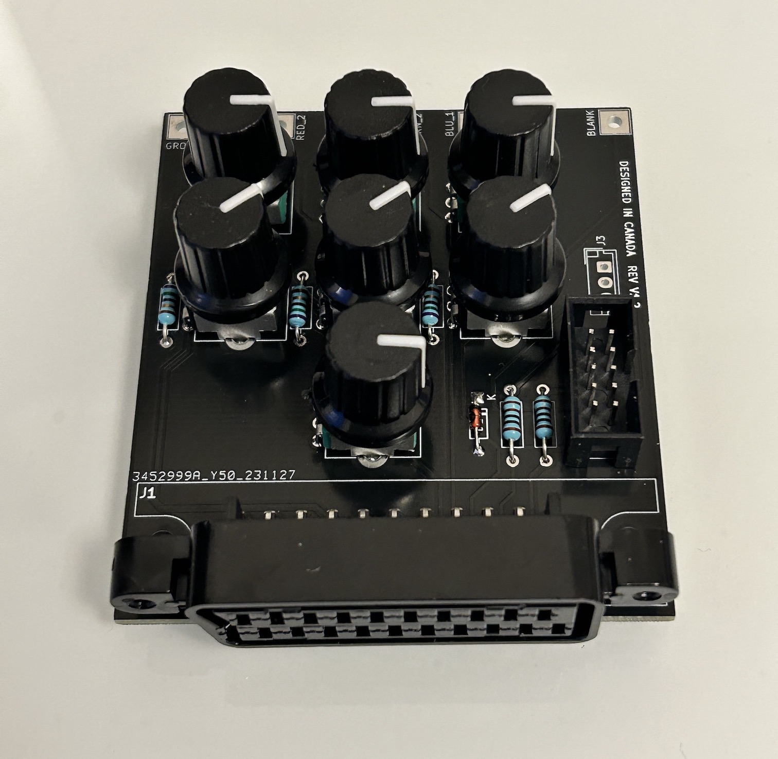
The RGB Tuner
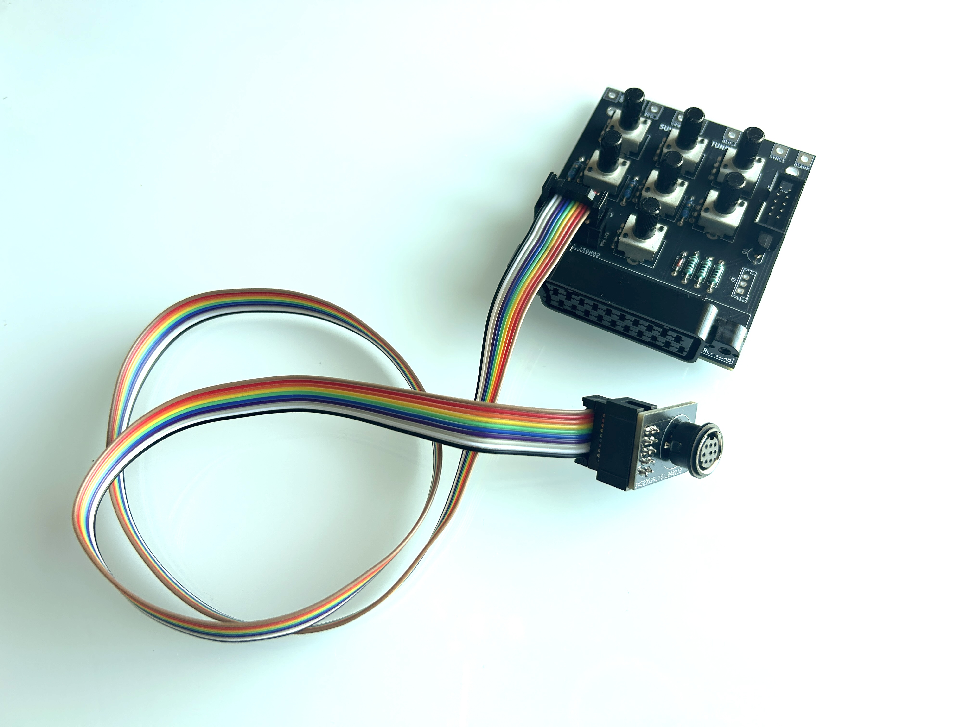 An RGB extension cable is attached. RGB can be fed here via an XRGB Mini, BNC connectors, or another full SCART port.
 Picture from an earlier 1.2 board
 Picture from an earlier 1.2 board
 Picture from an earlier 1.2 board
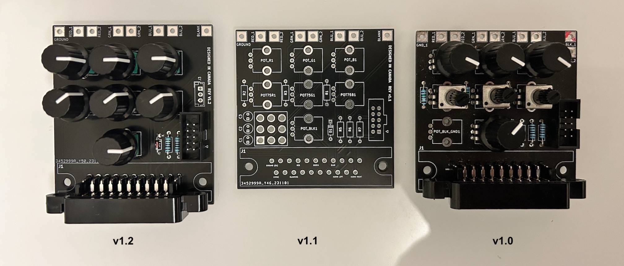
My learnings from the previous revisions are the following.
- Don't make the board overly complicated. Let it just do one thing. Allow you to tune blanking voltage and inline resistor values.
- Leave enough space to easily use the pots
- Have an extension cable so that you can see what's going on in front of the set
- There is no interference, even with a 3 feet ribbon cable. It's all in the way you RGB mod the set
- Use quality pots acquired from DigiKey or Mouser
It took several revisions to test out various concepts. v1.2 is a slightly larger and simpler board, that I use with pretty much every RGB mod now.
Parts used
- RGB tuner board v1.4B
- 10pin IDC male connector
- Female SCART connector
- IDC ribbon cable
- 3x 75 ohm resistors (termination resistors) - RNF14FTD75R0
- 2x 1 kohm resistors (2 for audio, 1 for transistor) - RNF14FTD1K00
- 1x PN2222A transistor
- 1x 1N4148 diode
- 4x Potentiometers 1K 20% 9MM CARBON POT
- 3x Potentiometers 10K 20% 9MM CARBON POT
You can also probably use other pots.
Can I buy this?
This board is produced in very limited quantities. If it’s currently available, please purchase it through the https://store.sunthar.com. If it’s sold out, join the waitlist and you’ll be notified as soon as more units are available.