Toshiba 27AFX54+
Toshiba 27AFX54+ CRT RGB mod
The Toshiba 27AFX54 is a 27" flat-screen CRT television released in 2004 as part of the premium "Cinema Series" line.
It is well-regarded for its crisp picture quality, built-in component video inputs, and 16:9 vertical compression features. However, it does have minor screen geometry quirks that can be noticeable in horizontally scrolling games.
View full CRT details and more mod examples →
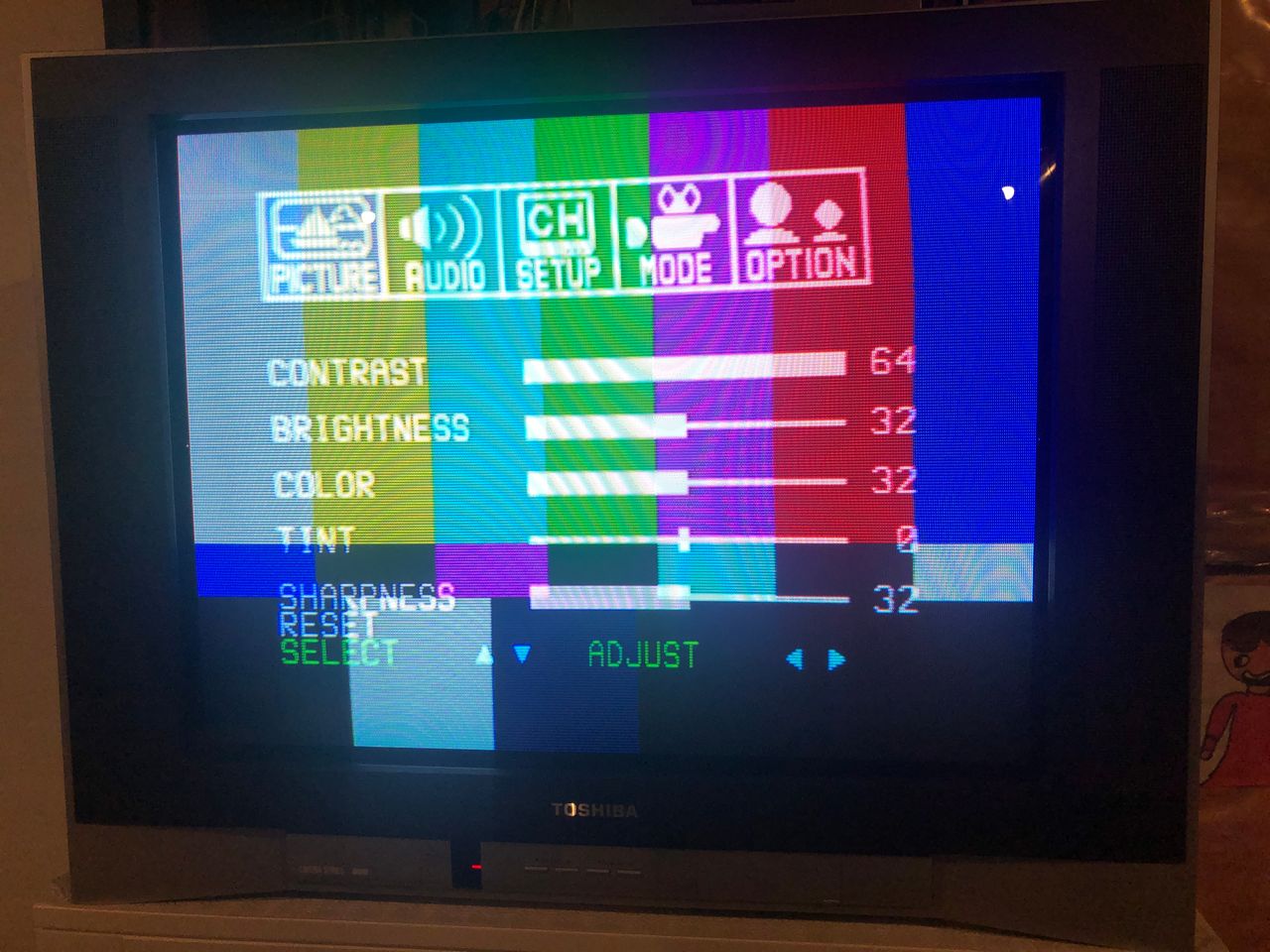
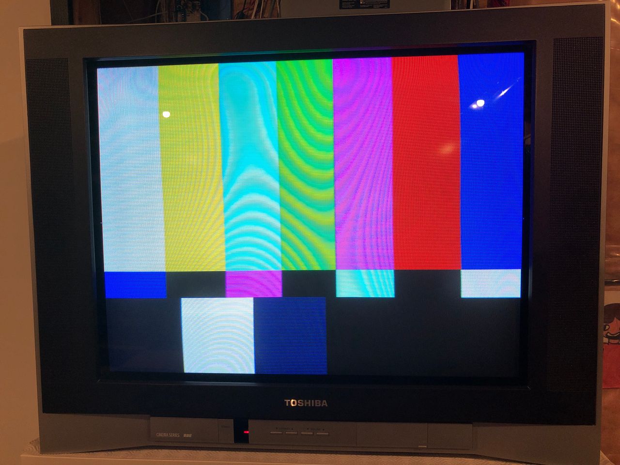
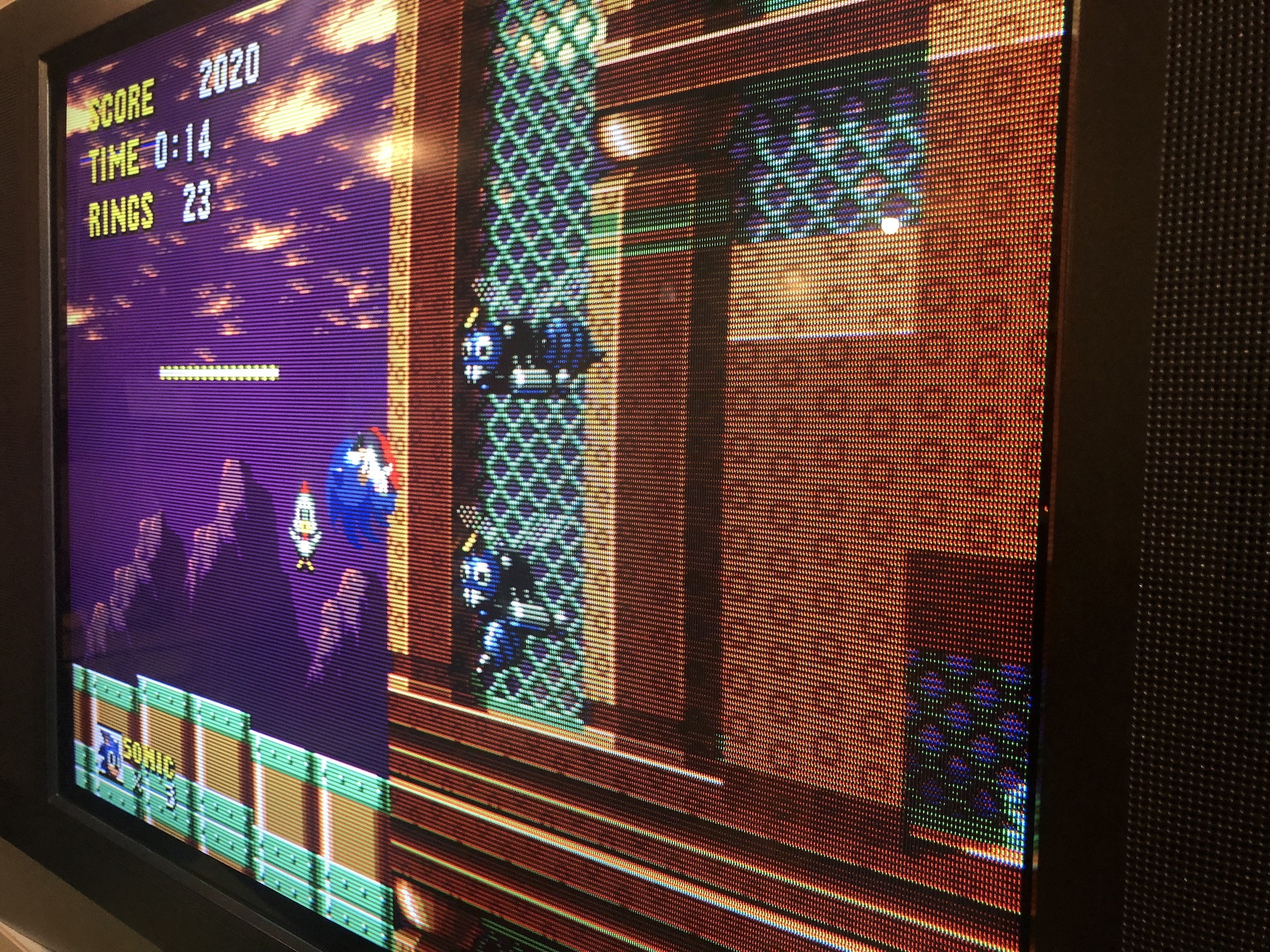 Picture from Toshiba 27AFX54 (Cinema Series)
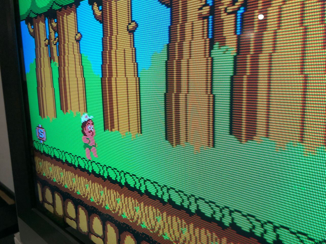
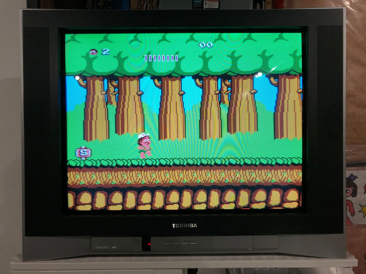
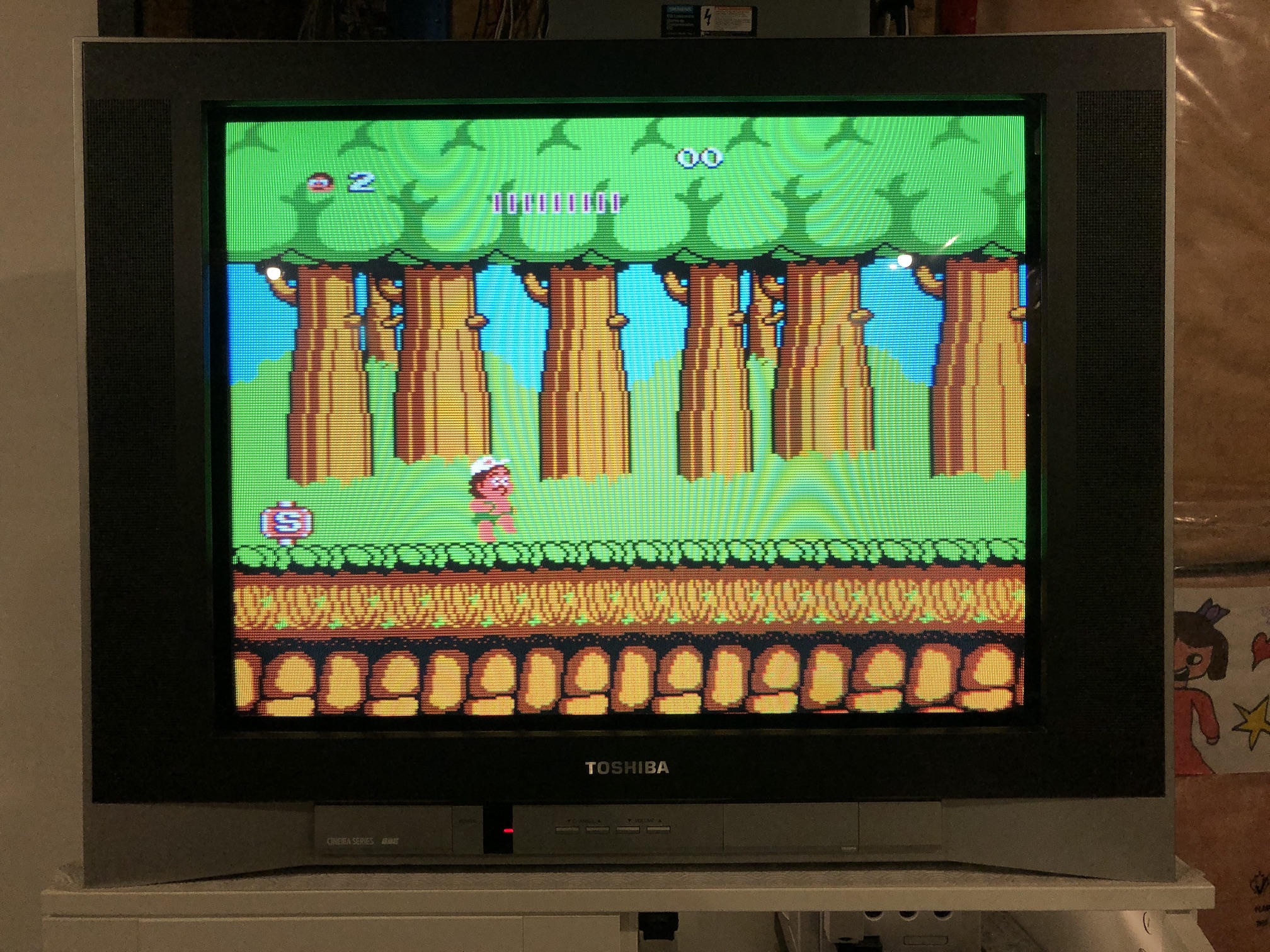 NES Adventure Island
Please also see other Toshiba AF series mods, as the instructions are more or less the same.
Table of Contents
Contributors
Thank you to everyone who contributed to this guide:
- Sunthar — contributor, RGB mod and pictures
CRT safety
Caution
You can die doing this! So read carefully! CRT TV is not a toy. Do not open a CRT TV. If you don't have any prior knowledge about handling high voltage devices, this guide is not for you. CRT TV contains high enough voltage (20,000+ V) and current to be deadly, even when it is turned off.
Plan of attack
Manuals and Datasheets
Specs
- Year: 2005
- Format: NTSC
- Tube: LG A68QCU770X66L
- Jungle Chip: Renesas M61283FP
- OSD Chip: Orion OEC7092A
- Screen Size: 27"
- Weight: 88.2 lbs
- Inputs: Composite, S-Video, RF, Component YPbPr
Schematics
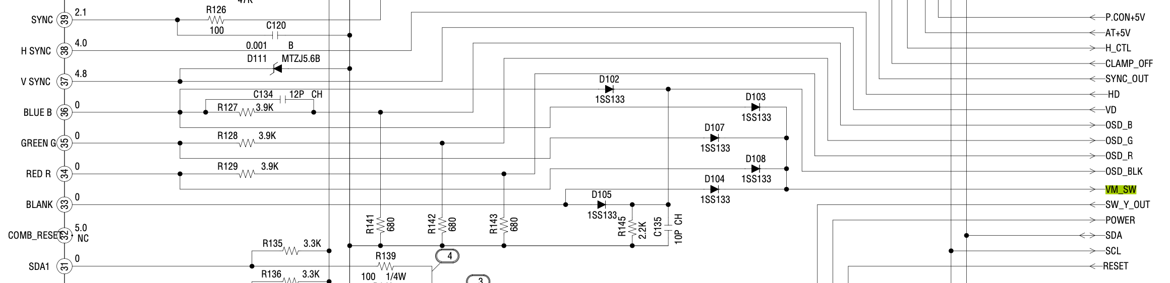
RGB mux diagram
Prepare the mux diagram. If you are building your own circuit, this diagram should help.
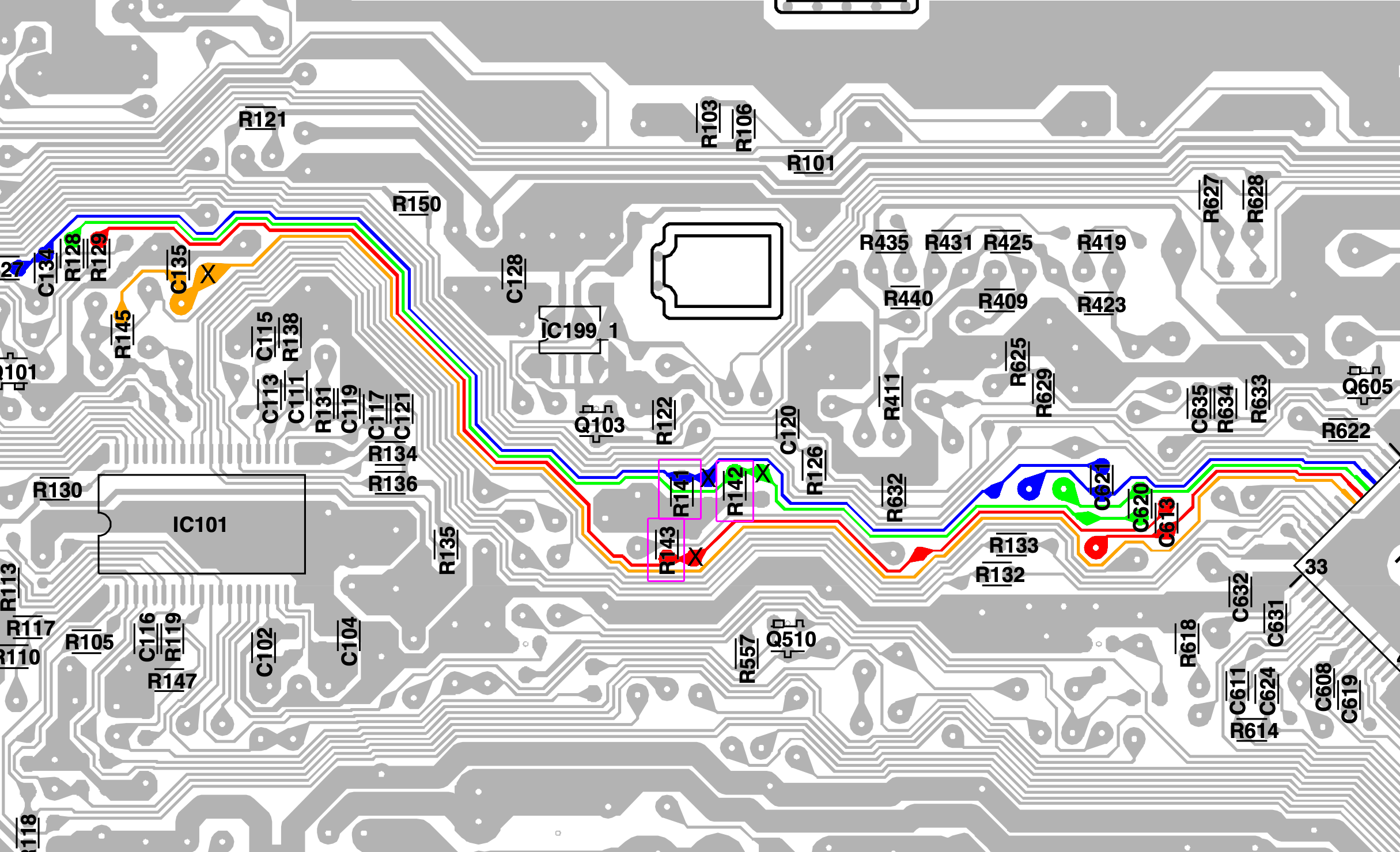
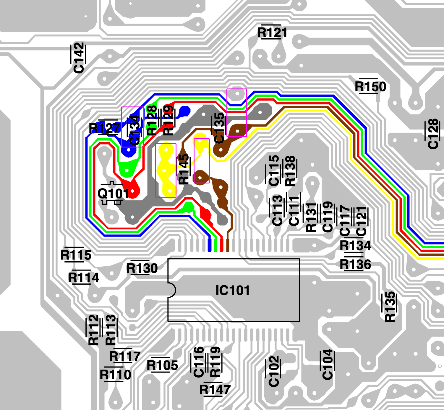
PCB
Points where the R, G, B and Blank wires should be connected are marked "X". Pink boxes show the resistors, diodes that needs to be removed.
Warning
27AF54X model has a minor interference that is noticeable with certain color gradients (grey, purple) on the screen.
This interference is reduced by attaching the Wii component cables and audio cables. This issue was noticed on two TV's of the same model #, so it is not specific to the TV. This interference was not noticed on Toshiba 27AF43, which has a completely different PCB layout.
One potential approach is to remove the original 0.1 µF capacitors and implement the capacitor and diode used in the Toshiba 24AF43 mod. The RGB signals would then be injected after the diode stage. In theory, this should significantly reduce the ringing artifacts, as you prevent signal reflections from the OSD chip.
Performing the mod
STEP 1: Remove the following components
Remove RGB resistors to ground
- R141
- R142
- R143
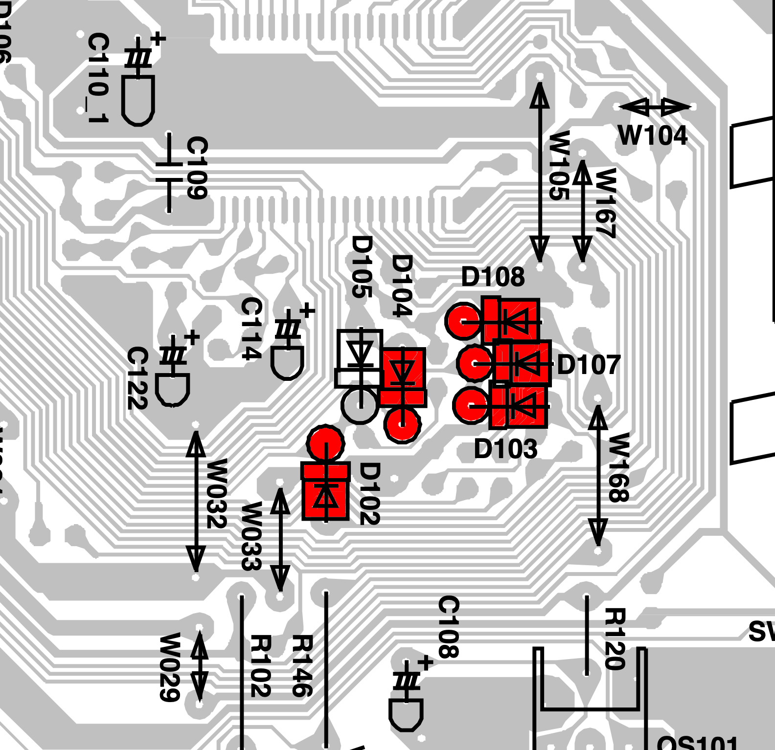
(Optional) Removed the diodes that enable the edge enhancer. Doesn't do much to fix the minor jitter/interference seen on this particular TV. However, simplifies the RGB lines.
- D102
- D104
- D108
- D107
- D103
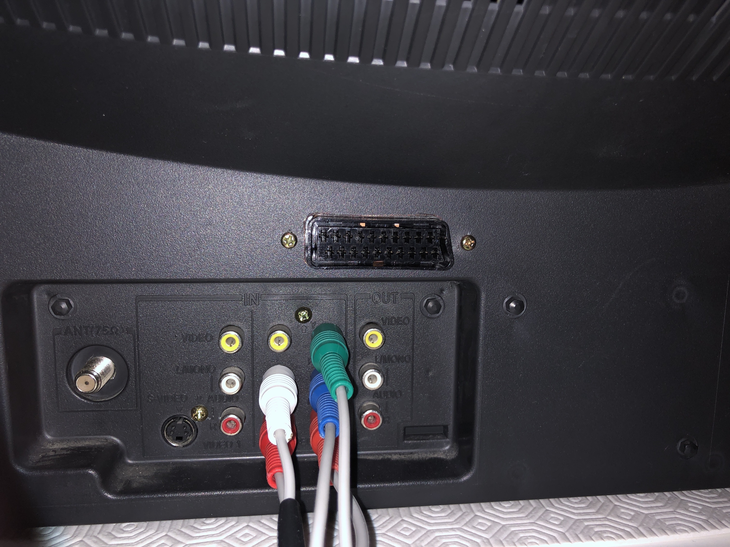
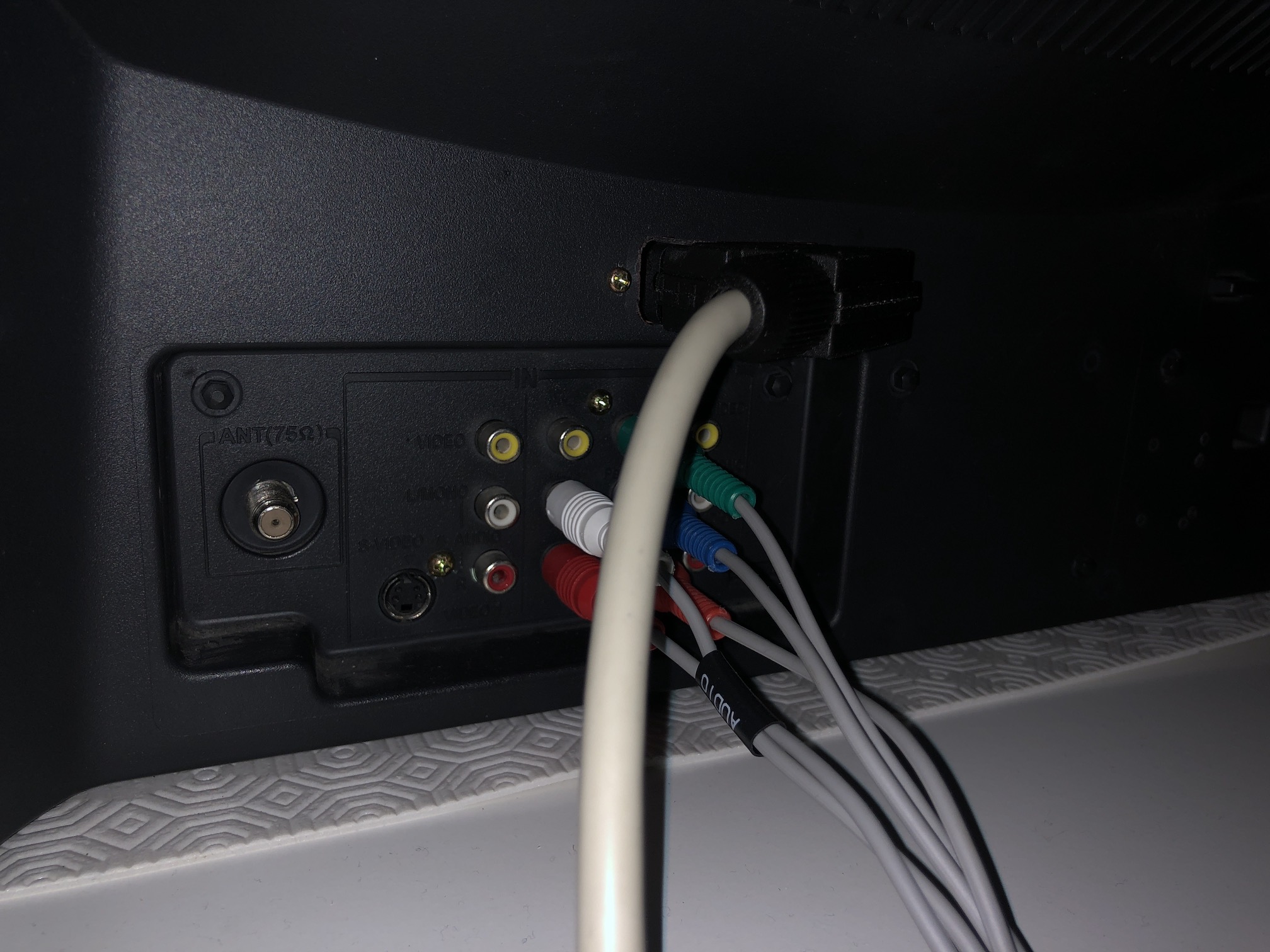
STEP 2: Connect RGBs, Blanking and Audio
- Brown wire = blank
- Red wire = red
- Blue wire = blue
- Green wire = green
- Yellow wire = csync
- Organge wire = video ground
- Grey wire = audio right
- White wire = audio left
- Purple = audio ground
- Black = common ground
Connect the R, G, B and blanking (orange) wire. ![]()
Connect the SIGNAL, AUDIO RIGHT, AUDIO LEFT, GROUND wires 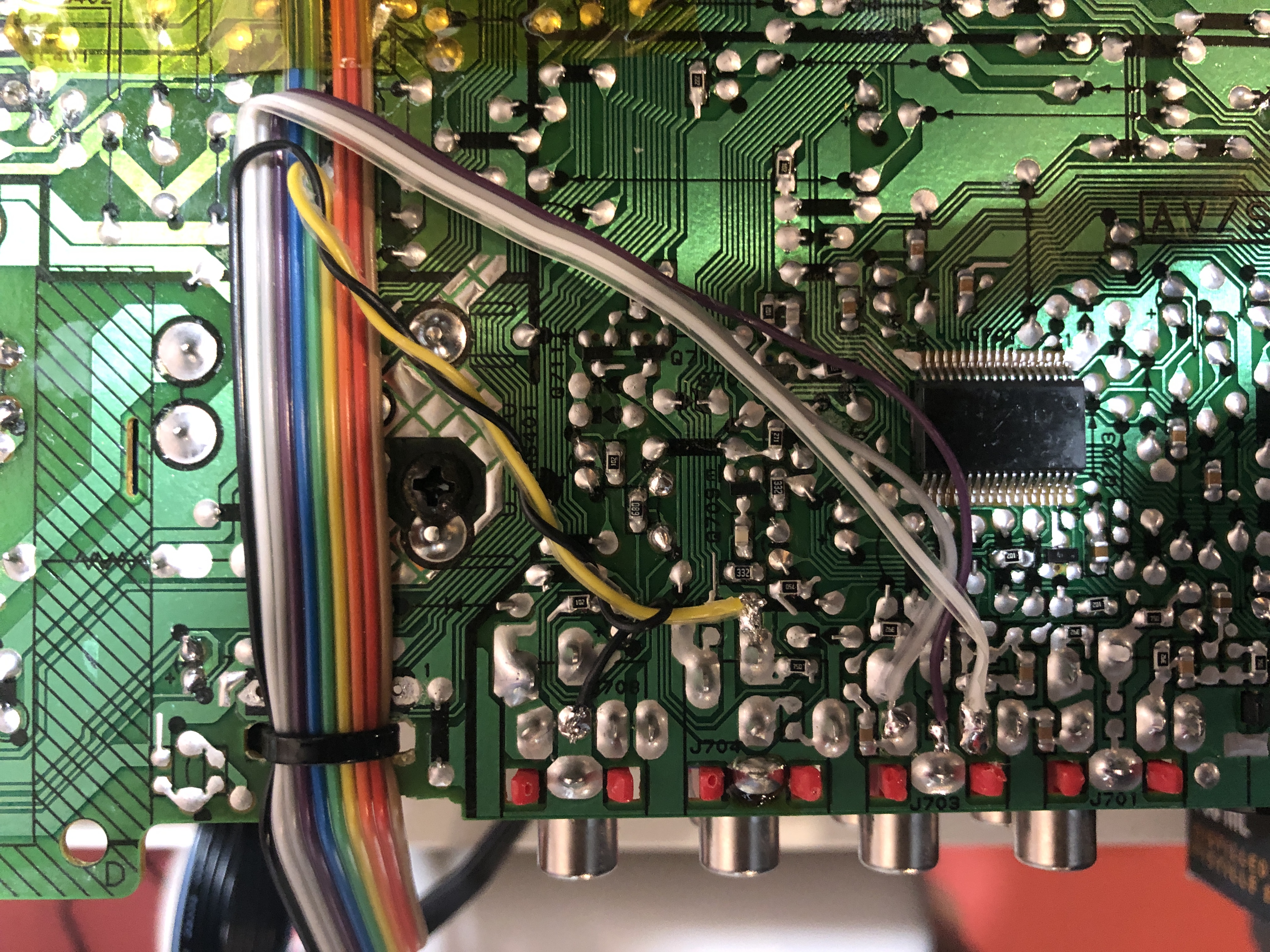
Full mod 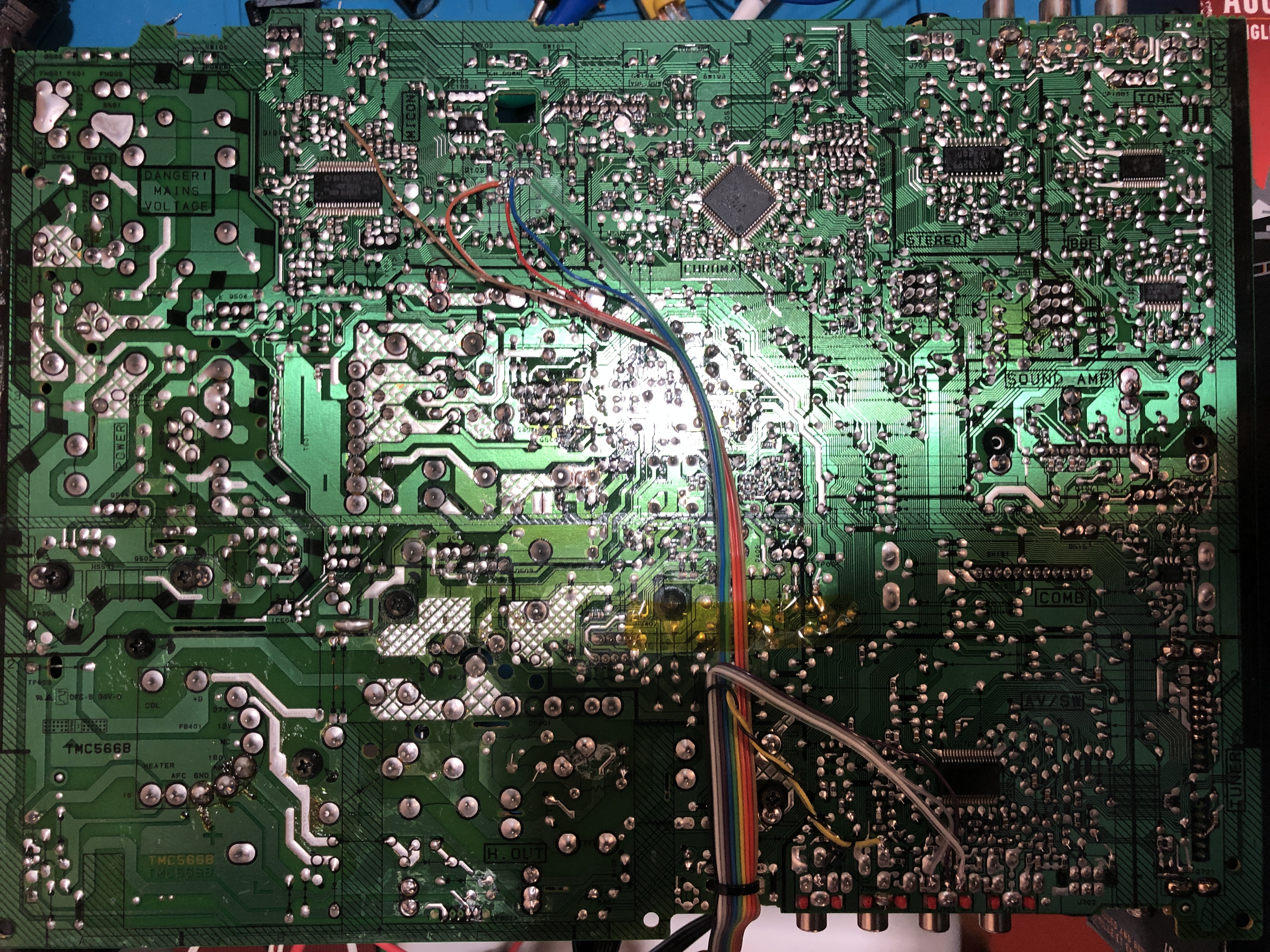
STEP 3: Prepare your RGB mux circuit
M61283FP can handle a peak to peak voltage of 0.7 in the external RGB lines.
Depending on the RGB/OSD stock resistors your CRT has, use the below inline resistors.
This mod uses the RGB mux board. This is optional, but will make your mod easier and stable. You can also create the circuit presented in the schematics above without the board. Please also checkout the mux calculator to play with your own values.
| On Toshiba CRT Chassis | 27AFX54 |
|---|---|
| CRT RGB inline resistor | 3.9kΩ |
| CRT RGB ground resistors removed | 680Ω |
| 0.1μF caps replaced | Yes |
| Add diodes on chassis RGB lines? | Yes |
| Add blanking diode on chassis | No |
| RGB mux board | 27AFX54 |
|---|---|
| Mux board RGB termination (R1, R2, R3) | 75Ω |
| Mux board RGB inline resistors (R4, R5, R6) | 1kΩ |
| Mux board Audio LR (R7, R8) | 1kΩ |
| Mux board blanking diode (R9) | 1N4148 |
| Mux board blanking ground resistor (R10) | open |
| Mux board blanking resistor (R11) | short |
Compatible mux boards:
Sample Toshiba 20AF44 RGB Mux Adapter 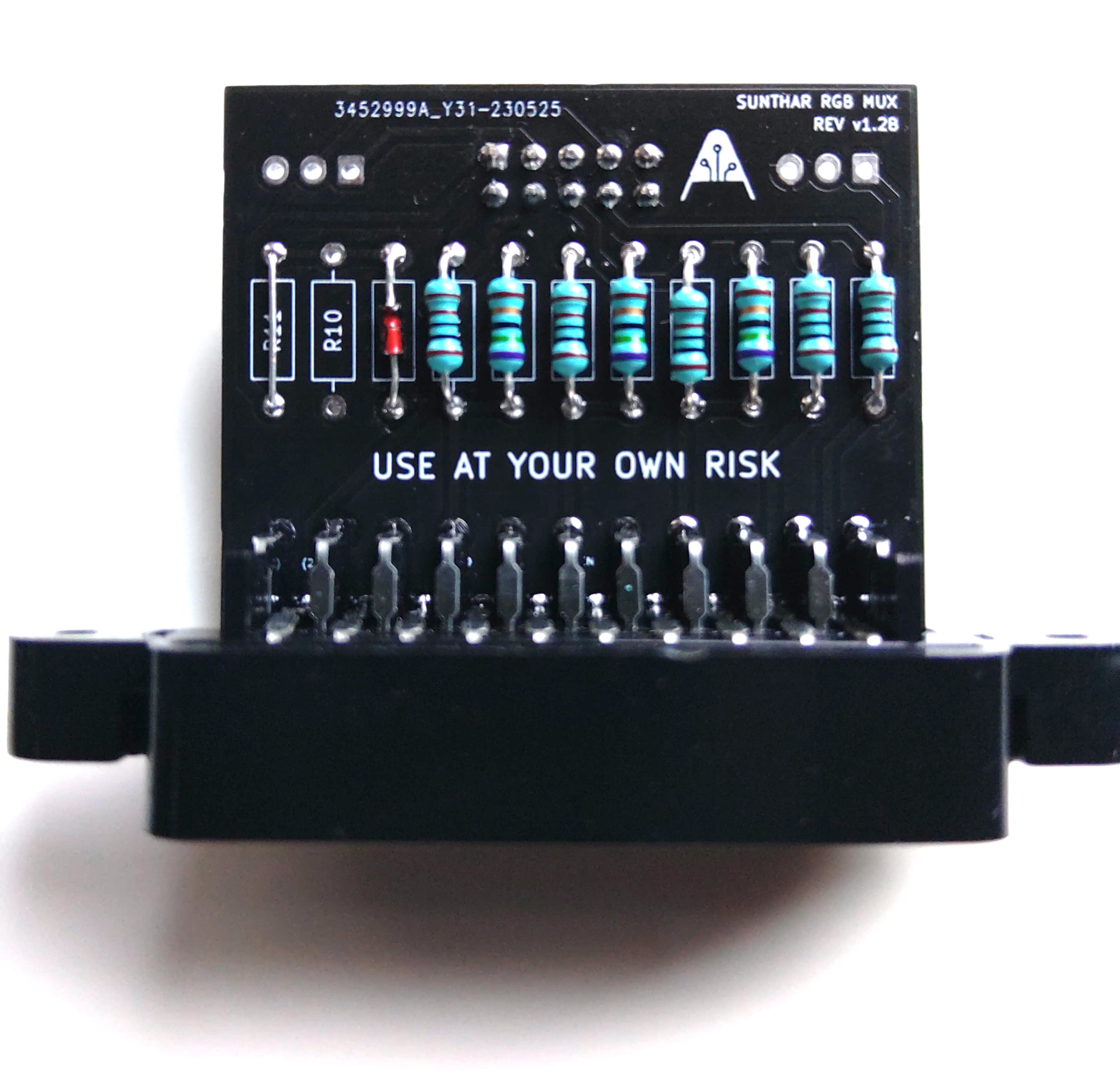
STEP 4: Attach the female SCART connector to TV
Creating a SCART cutout and mounting it is an art. I have a dedicated section for it.
How to create and mount a SCART female plug?
Toshiba 27AFX54 Pictures
OSD Mux Mod

Games
SNES - Contra 3 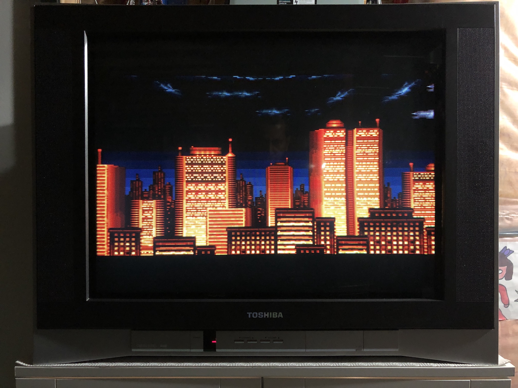
SNES - Contra 3 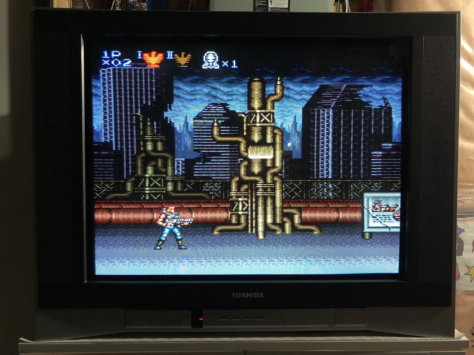
SNES - R-Type 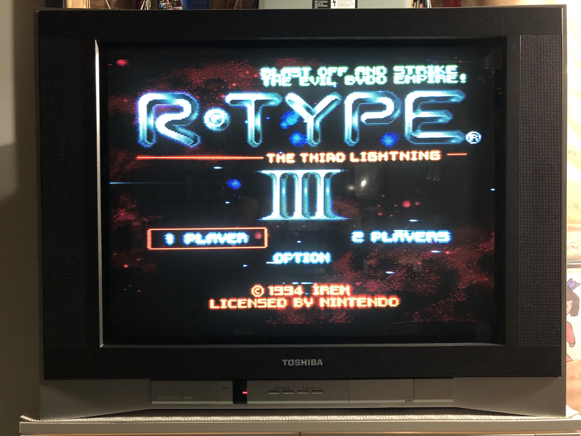
SNES - Super Metroid 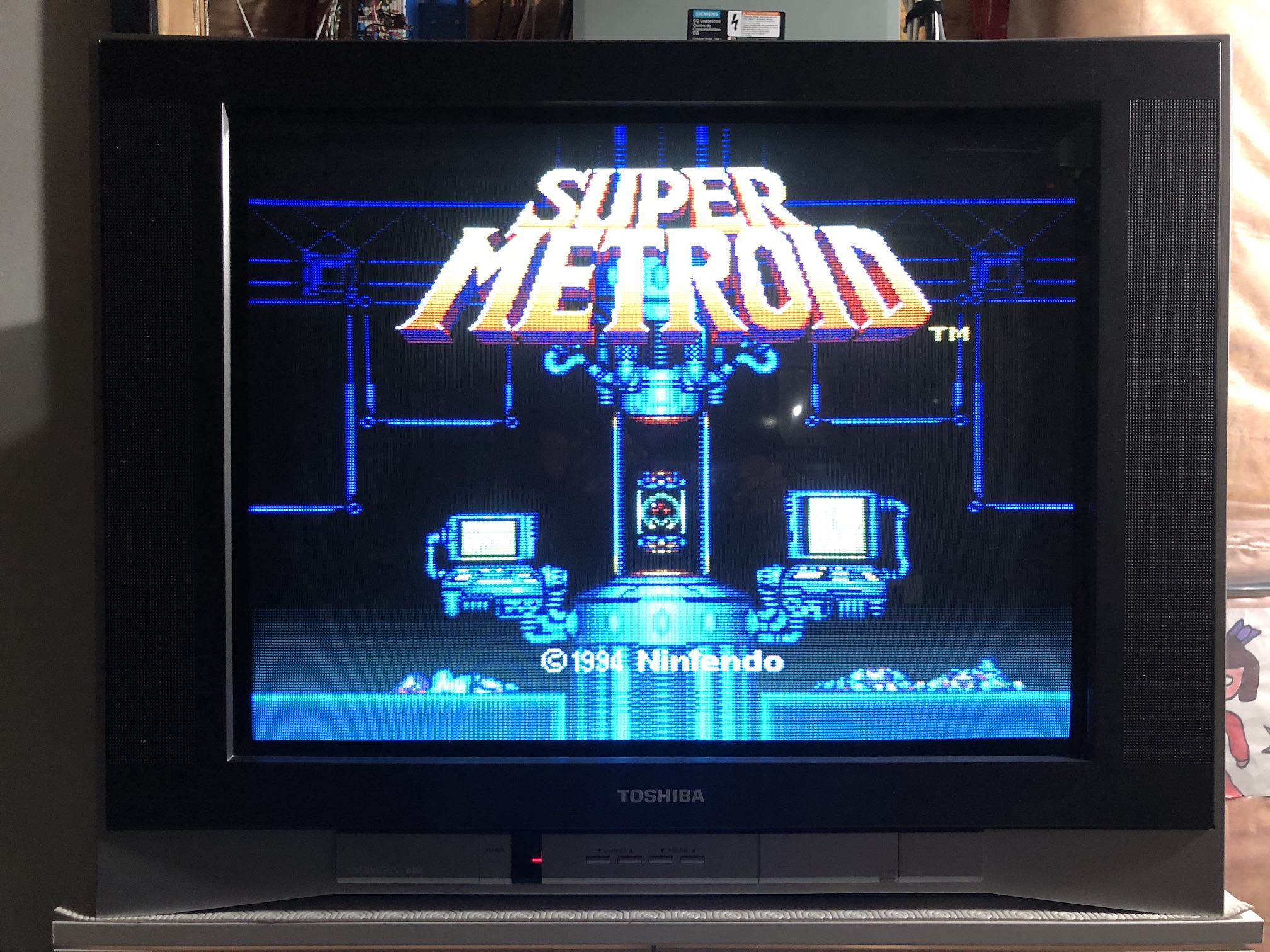
NES - Adventure Island
Test patterns
SMPTE 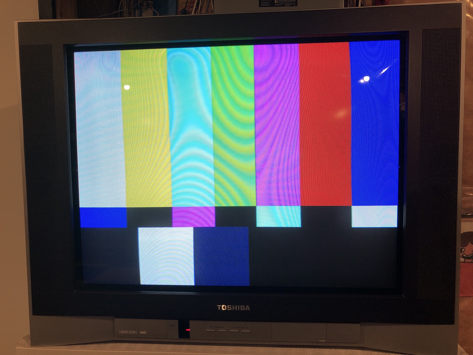
Convergence 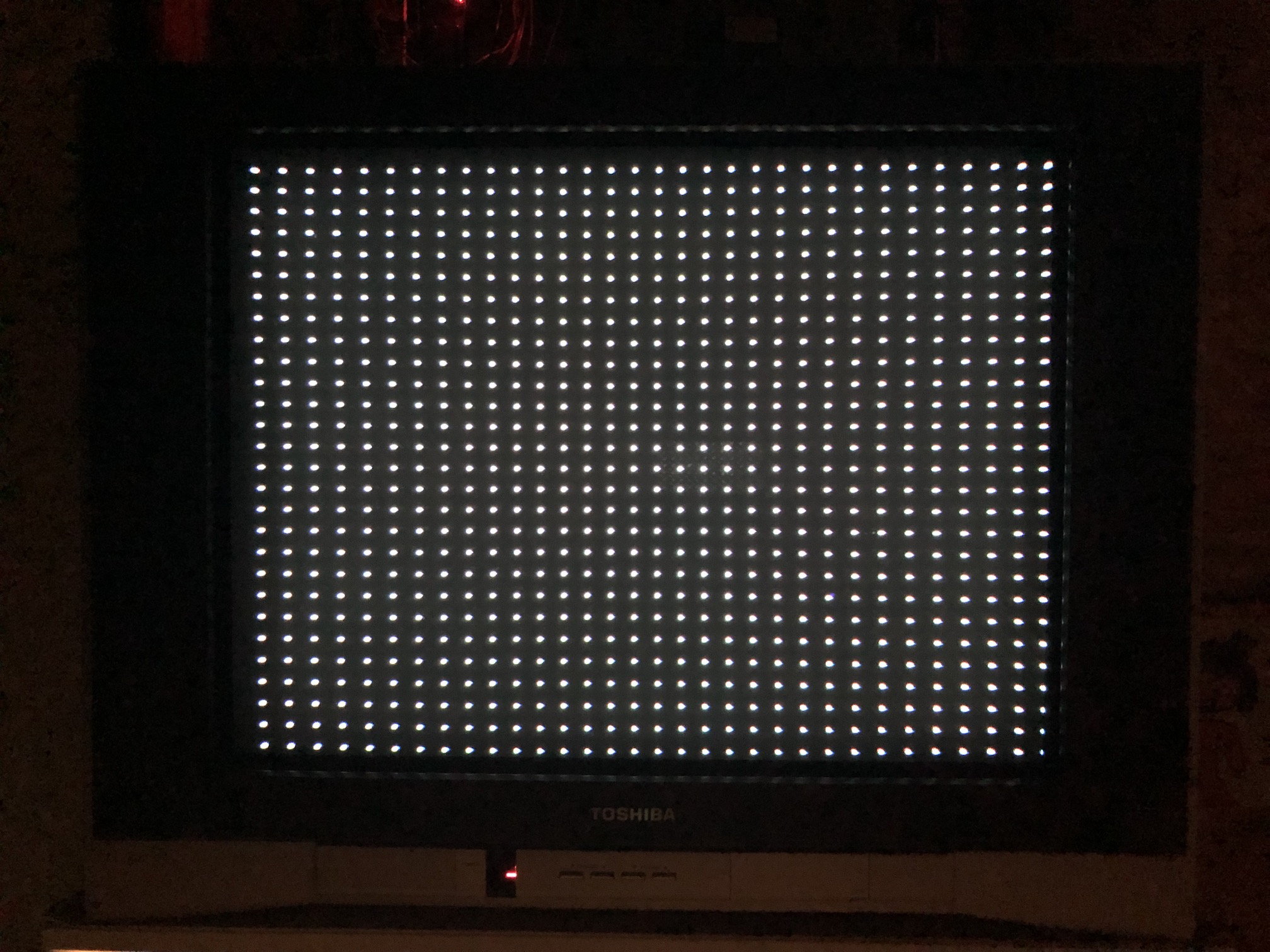
Grid - Geometry (yoke can be tilted a bit) 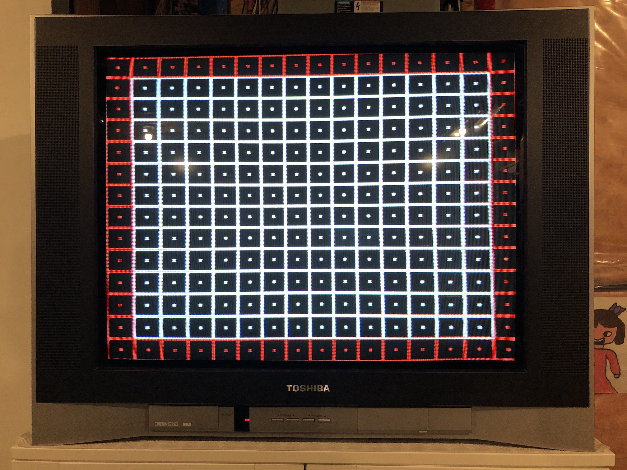
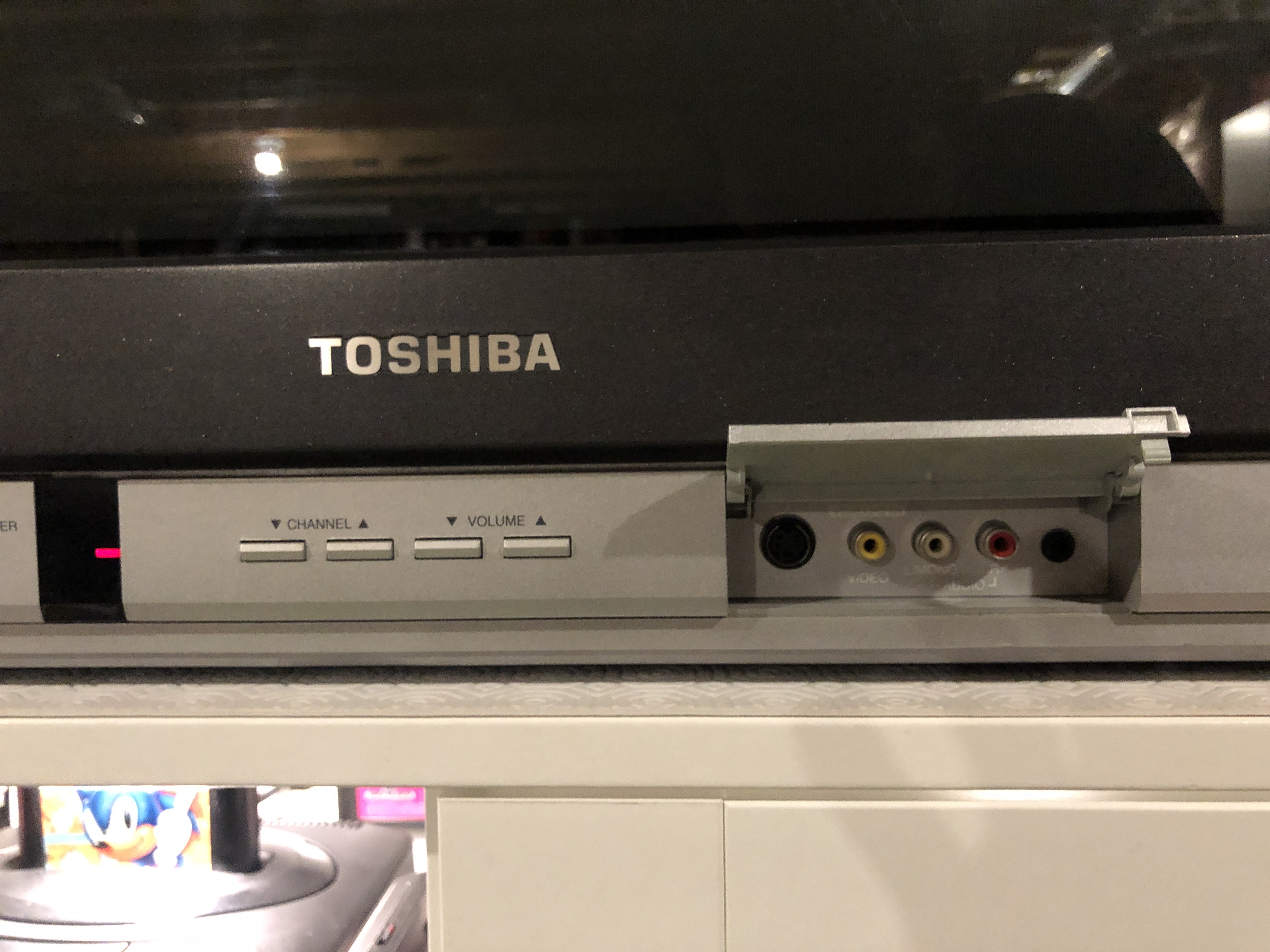
Front input
Service Menu Settings
| NUM | SETTING | VALUE | FIXED |
|---|---|---|---|
| 00 | OSD | 27 | DEFAULT |
| 01 | |||
| 02 | H VCO | 3 | DEFAULT |
| 03 | H PHASE | 10 | |
| 04 | AFC GAIN | 6 | |
| 05 | V SHIFT | 2 | DEFAULT |
| 06 | H.SIZE | 41 | |
| 07 | V.SIZE | 32 | |
| 08 | V.LIN | 29 | |
| 09 | VS.CORR | 25 | DEFAULT |
| 10 | R.DRV_M | 74 | |
| 11 | B.DRV_M | 68 | |
| 12 | R.BIAS_M | 47 | |
| 13 | G.BIAS_M | 44 | |
| 14 | B.BIAS_M | 32 | |
| 15 | BRI.MAX | 105 | DEFAULT |
| 16 | BRI.CENT | 88 | |
| 17 | BRI.MIN | 55 | DEFAULT |
| 18 | CONT.MAX | 70 | |
| 19 | CONT.CENT | 60 | DEFAULT |
| 20 | CONT.MIN | 10 | DEFAULT |
| 21 | COL.MAX | 80 | DEFAULT |
| 22 | COL.CENT | 65 | |
| 23 | COL.MIN | 0 | DEFAULT |
| 24 | TINT | 50 | |
| 25 | SHARP | 40 | DEFAULT |
| 26 | CB DL | 0 | DEFAULT |
| 27 | CR DL | 0 | DEFAULT |
| 28 | CB PED | 8 | DEFAULT |
| 29 | CR PED | 8 | DEFAULT |
| 30 | PARABOLA | 51 | |
| 31 | CORNER | 33 | |
| 32 | TRAPEZIU | 27 | |
| 33 | LEVEL | 37 | |
| 34 | SEP1 | 11 | |
| 35 | SEP2 | 40 |
Recapping
| V | uF | Location | Current Temp | Diameter/Size | Location Description |
|---|---|---|---|---|---|
| 50 | 2.2 | C406, C422 | 85 | 5.1mm | Deflection |
| 25 | 2200 | C408 | 85 | 12.6mm | Deflection |
| 50 | 10 | C409 | 85 | 5mm | Deflection |
| 35 | 100 | C407 | 85 | 6.4mm | Deflection |
| 250 | 1 | C443 | 85 | 8mm | Deflection |
| 50 | 22 | C403 | 85 | 5.1mm | Deflection |
| 100 | 22 | C430 | 85 | 6.5mm | Deflection |
| 16 | 100 | C411 | 85 | 5.1mm | Deflection |
| 35 | 2200 | C413 | 85 | 16.2mm | Deflection |
| 250 | 22 | C426 | 85 | 10.2mm | Deflection |
| 16 | 1000 | C511, C527, C542, C540 | 85 | 10.2mm | Power |
| 50 | 10 | C504, C514 | 85 | 5mm | Power |
| 25 | 47 | C509 | 85 | 5.2mm | Power |
| 10 | 2200 | C537 | 85 | 10.2mm | Power |
| 35 | 2200 | C501 | 85 | 12.6mm | Power |
| 25 | 1000 | C1009, C1004 | 85 | 10.1mm | Audio |
| 35 | 1000 | C1003 | 85 | 12.85mm | Audio |
| 16 | 1000 | C629 | 85 | 10.2mm | Chroma |
| 50 | 6.8 | C442 | 105 | 18.15mm | Deflection |
Capacitor codes and references
| Capacitor Codes | Board Function |
|---|---|
| C4xx | Deflection |
| C5xx | Power |
| C6xx | |
| C7xx | |
| C8xx | Neck Board |
| C9xx | Tuner |
| C10xx | Audio |
If you're not confident in cutting the SCART port yourself, I recommend going with the variant C of the board along with the trim plate for a cleaner, more professional look.
Pictures
Reference Photos