Sylvania 6413CTA
Sylvania 6413CTA CRT RGB mod
This guide covers the RGB mod for the Sylvania 6413CTA CRT TV. Quality of this set was stunning. Don't pass up the opportunity to RGB modify a Sylvania set. This guide also applies to ST413A, F413TA and 6413TA models.
The Sylvania 6413CTA is a 13" CRT television manufactured by Funai. It has excellent composite picture quality and reliable geometry. You can get even better picture quality out of an RGB modified Sylvania 6413CTA.
Sylvania 6413CTA is RGB moddable, however Sylvania 6413CTB is not RGB moddable.
View full CRT details and more mod examples →
Contributors
Thank you to everyone who contributed to this guide:
- Sunthar — contributor, RGB mod pictures
CRT safety
Caution
You can die doing this! So read carefully! CRT TV is not a toy. Do not open a CRT TV. If you don't have any prior knowledge about handling high voltage devices, this guide is not for you. CRT TV contains high enough voltage (20,000+ V) and current to be deadly, even when it is turned off.
Plan of attack
Manuals and Datasheets
- Sylvania 6413CTA Service Manual
- Mitsubishi M61206FP Datasheet (Jungle)
- Mitsubishi M37272M8-175FP Datasheet (OSD)
Specs
- Manufactured: Malaysia (2000)
- Chassis: 6413CTA
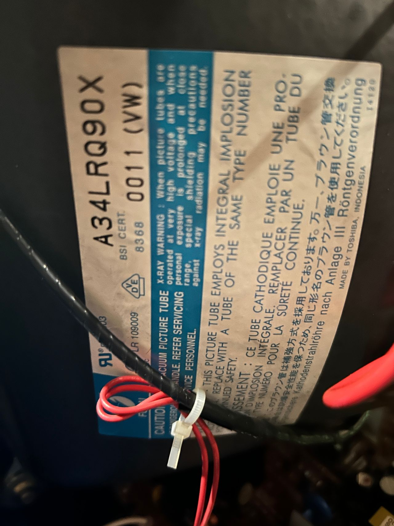
- Tube: Funai A34LRQ90X
- Jungle Chip: Mitsubishi M61206FP
- OSD Chip: Mitsubishi M37272M8-175FP
- Screen Size: 13"
- Power: 53 W
Schematics
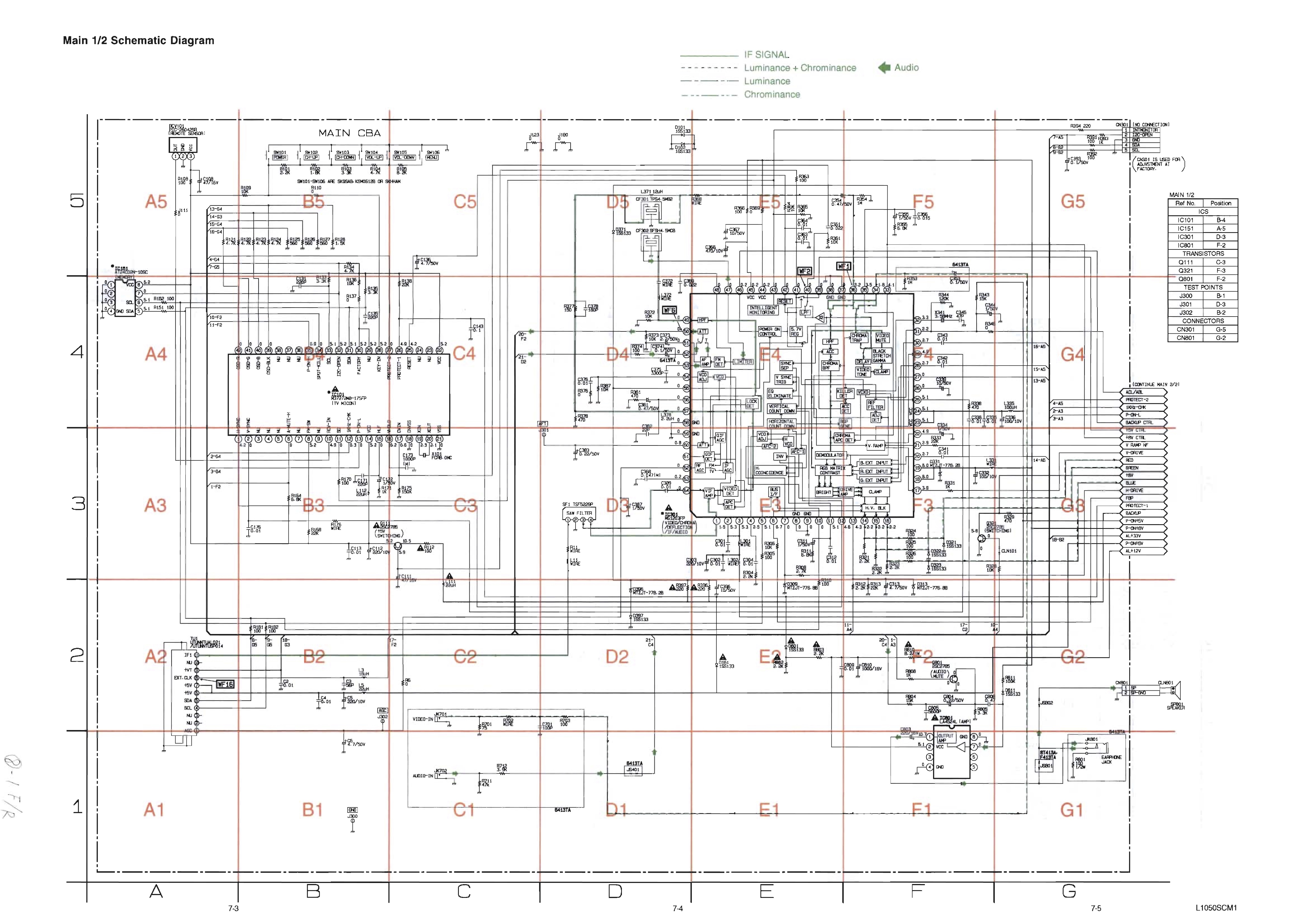
RGB mux diagram
Prepare the mux diagram. If you are building your own circuit, this diagram should help.
Performing the mod
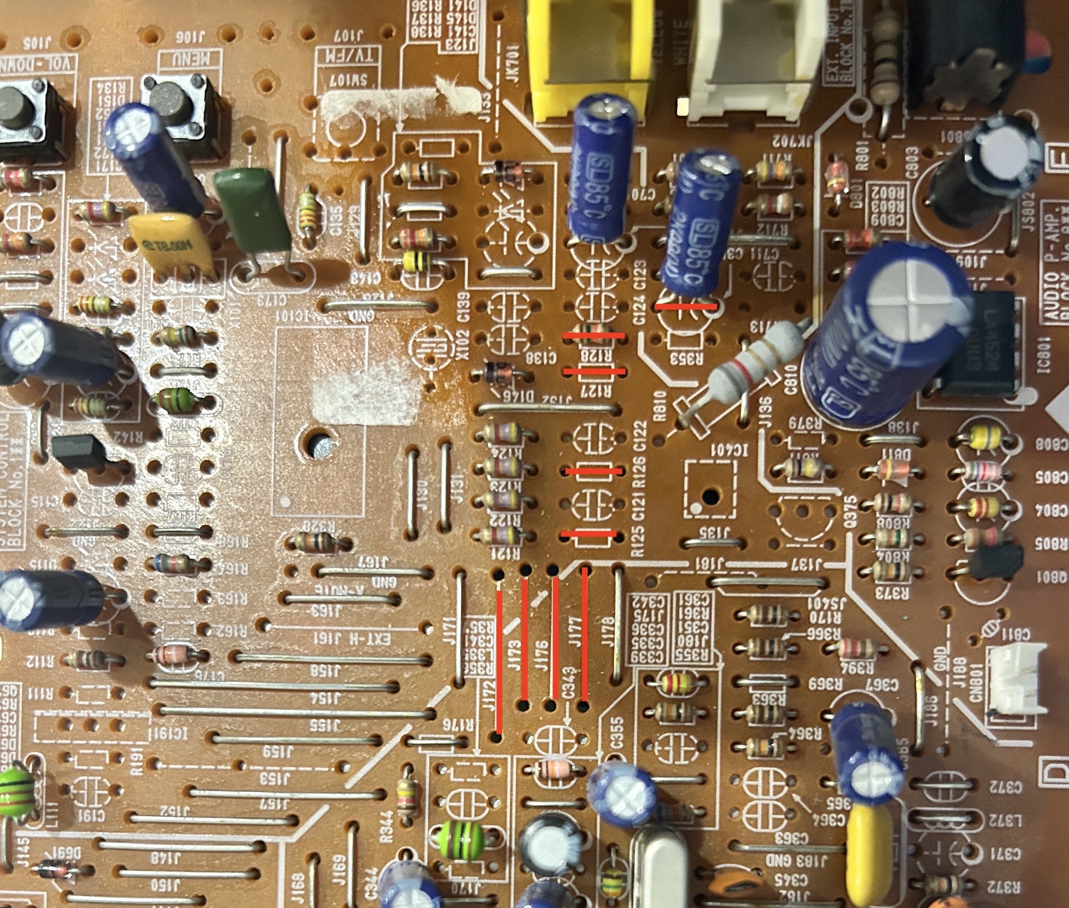
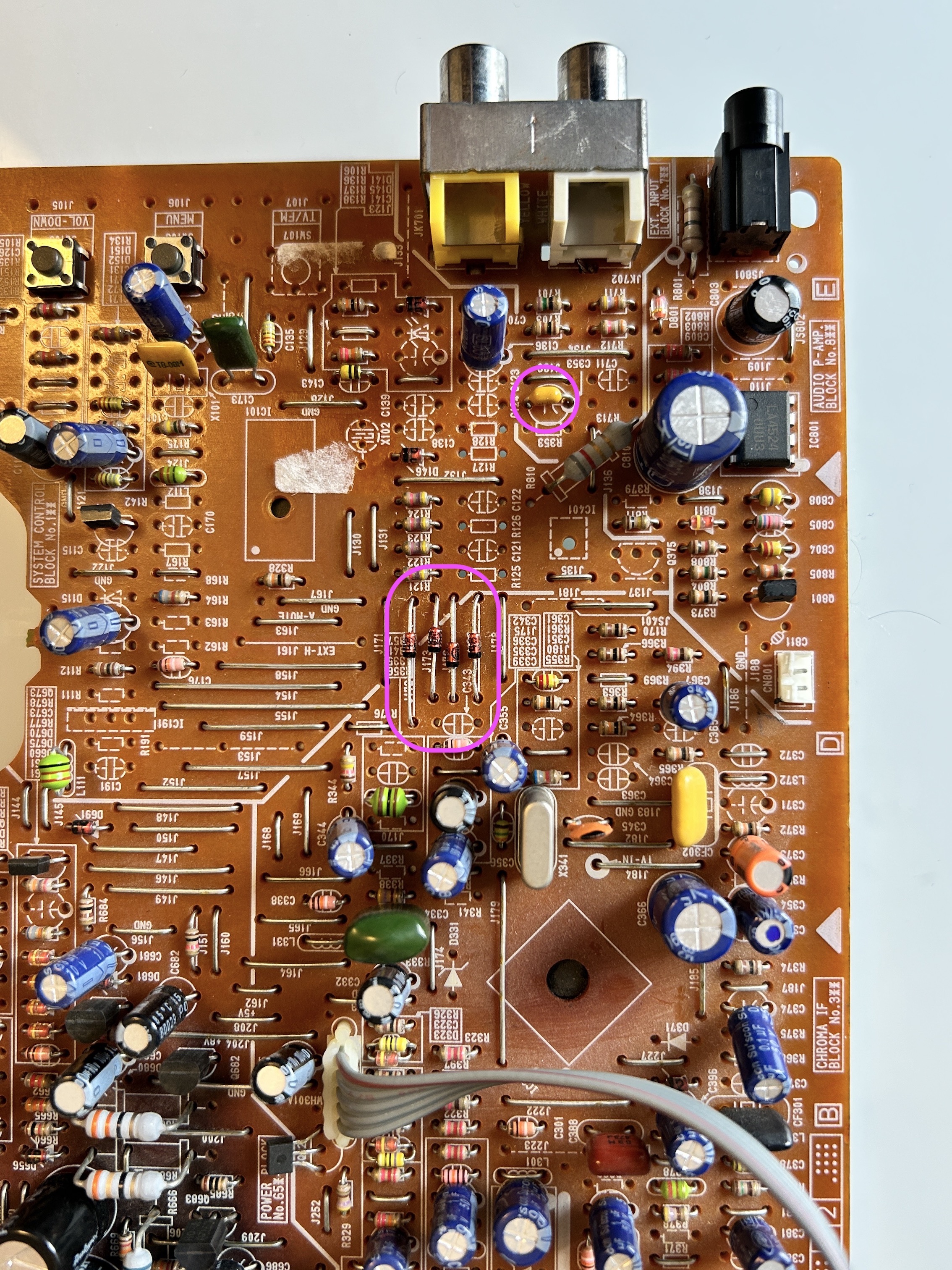
STEP 1: Remove the following components
Remove the RGB resistors to ground
- R125 (560Ω)
- R126 (560Ω)
- R127 (560Ω)
- R128 (1.5kΩ)
Yes, we are going to remove the blanking ground resistor (1.5 kΩ) R128 and put this on the mux circuit. Use 4.7kΩ on both R10 and R11. Otherwise with the voltage drop of the diode we are going to introduce, we will not see the OSD menu.
Remove the 4 jumpers
- J172
- J173
- J176
- J177
Remove the below capacitor
- C353 (we are going to replace this with a ceramic capacitor)
STEP 2: Add components
Replace the removed jumpers with 1N4148 diodes. Pay attention to the direction of the stripes.
Replace the removed 1uF, 50V electrolytic capacitor with 0.1uF, 50V ceramic capacitor. This is the capacitor that is in the sync line.
STEP 3: Connect Audio, RGB, Sync and Ground wires
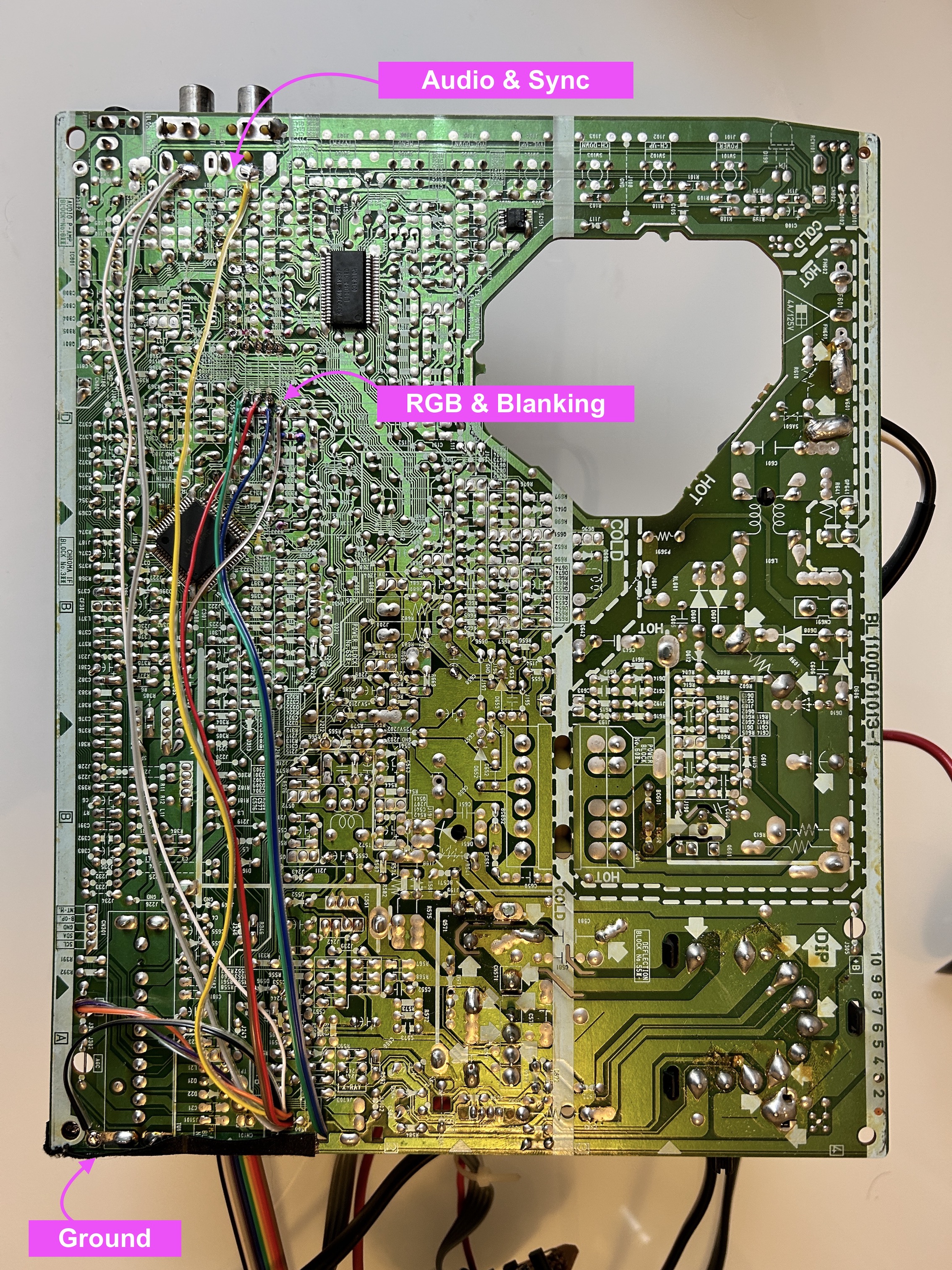
Pay close attention to where the R, G, B and Blanking wires are soldered. They should be soldered to the leg of the diodes that is closer to the chroma.
STEP 4: Build your mux circuit
This mod uses the RGB mux board. This is optional, but will make your mod easier and stable. You can also create the circuit presented in the schematics above without the board. Please also checkout the mux calculator to play with your own values.
| On Sylvania CRT Chassis | 6413CTA |
|---|---|
| CRT RGB inline resistor | 4.7kΩ |
| CRT RGB ground resistors removed | 560Ω |
| 0.1μF caps replaced | No |
| Add diodes on chassis RGB lines? | Yes |
| Add blanking diode on chassis | No |
| RGB mux board | 6413CTA |
|---|---|
| Mux board RGB termination (R1, R2, R3) | 75Ω |
| Mux board RGB inline resistors (R4, R5, R6) | 680Ω |
| Mux board Audio LR (R7, R8) | 1kΩ |
| Mux board blanking diode (R9) | 1N4148 |
| Mux board blanking ground resistor (R10) | 4.7kΩ |
| Mux board blanking resistor (R11) | 4.7kΩ |
Compatible mux boards:
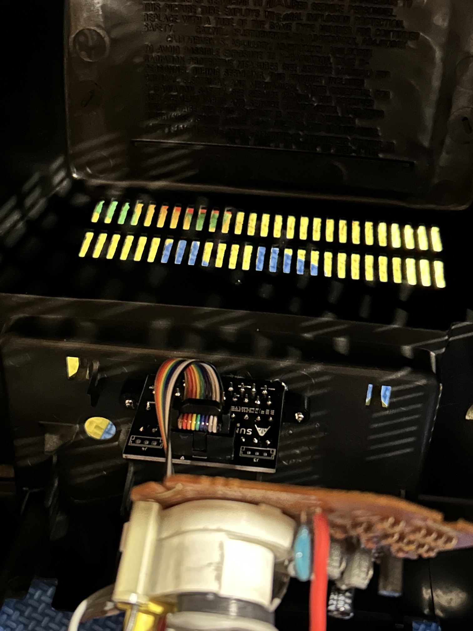
RGB mux adapter 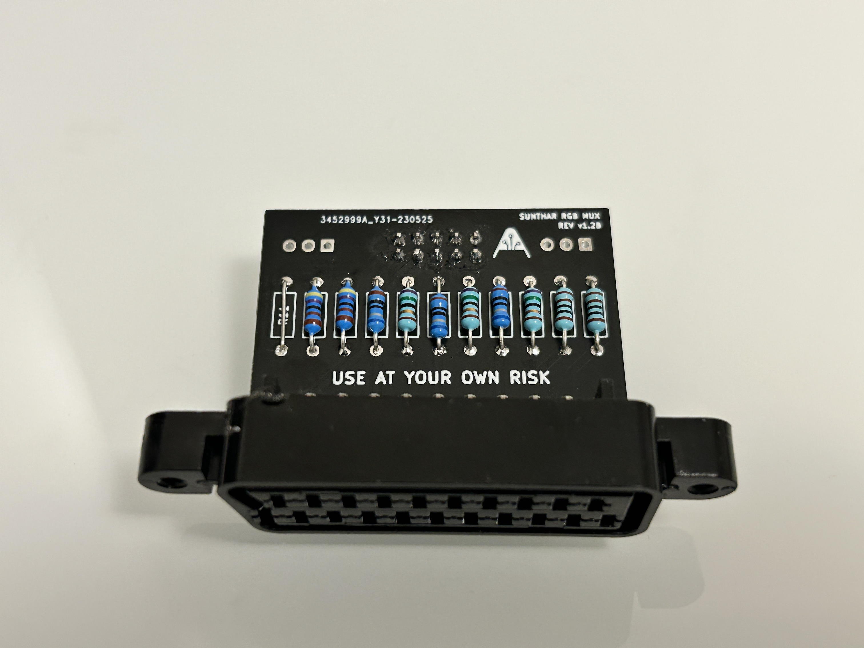
STEP 5: Attach the female SCART connector to TV
Creating a SCART cutout and mounting it is an art. I have a dedicated section for it.
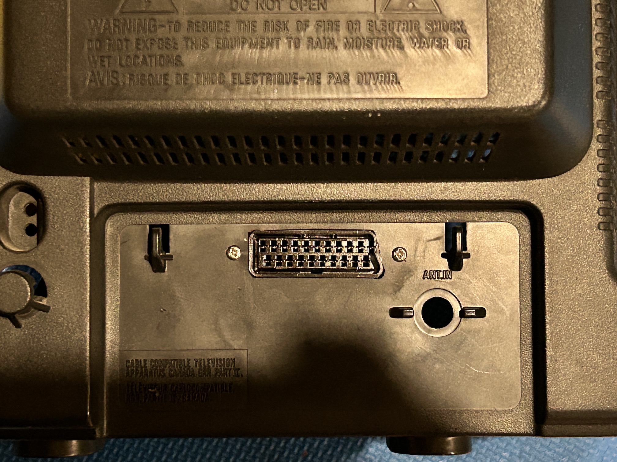
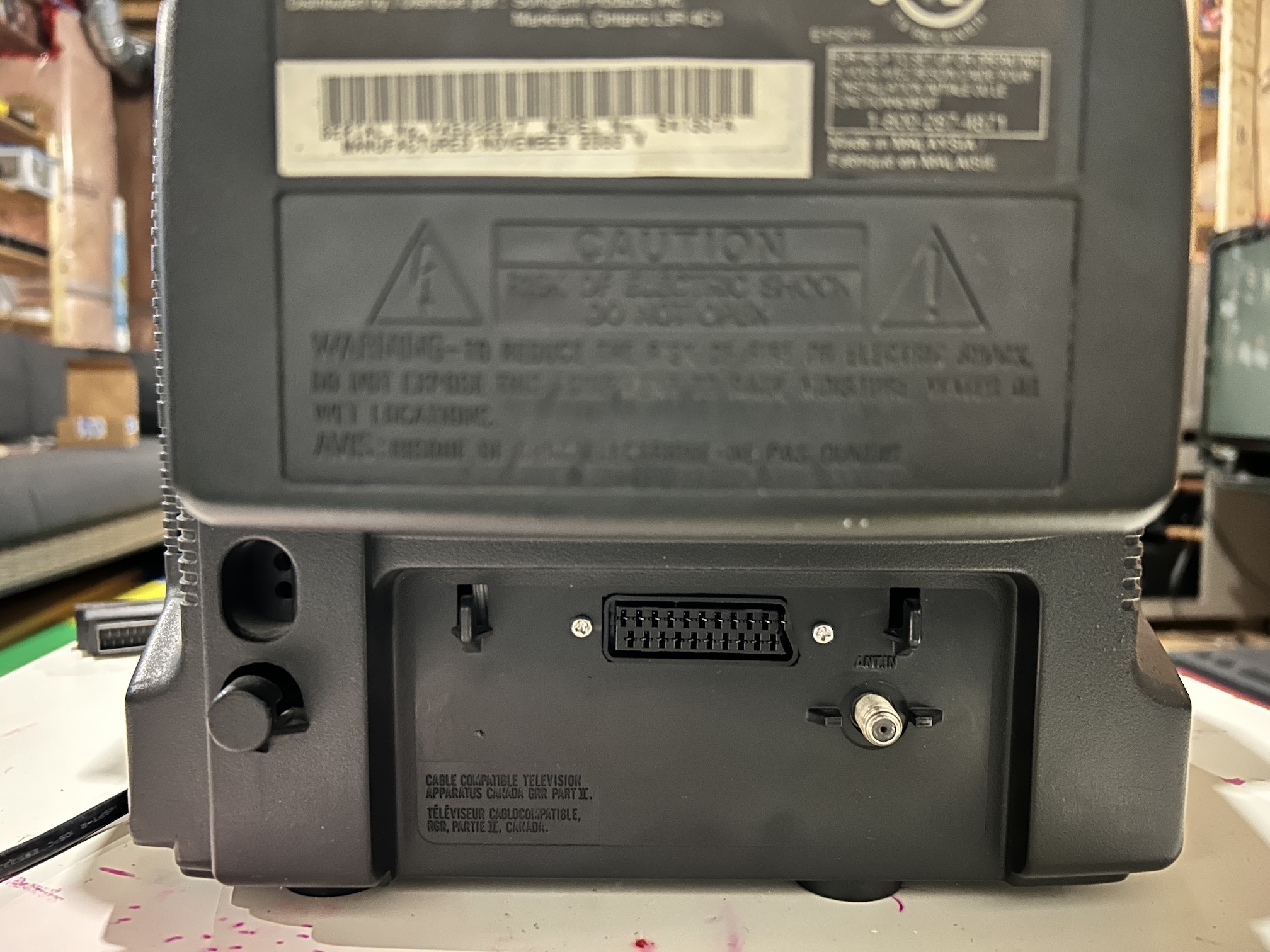
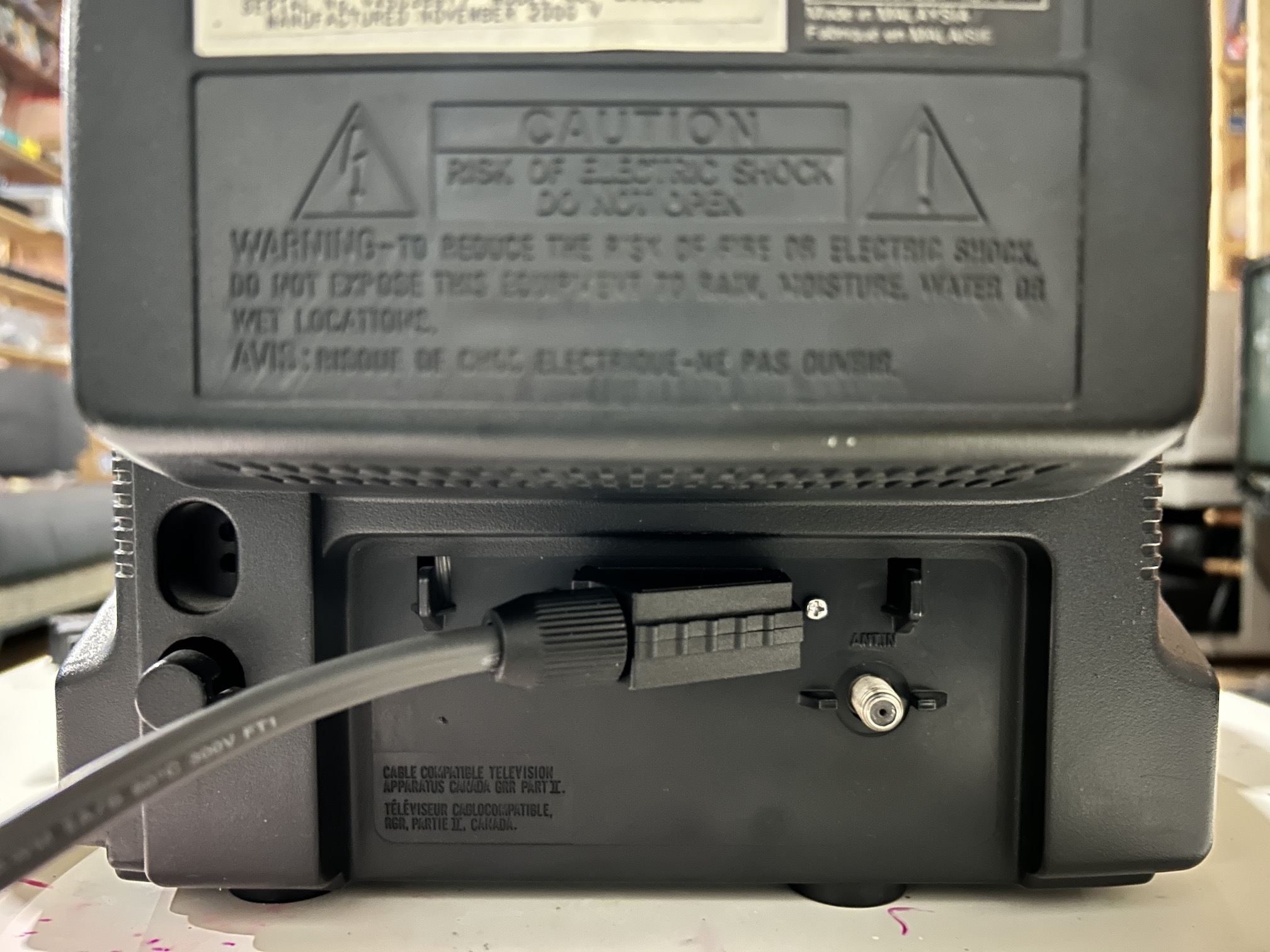
How to create and mount a SCART female plug?
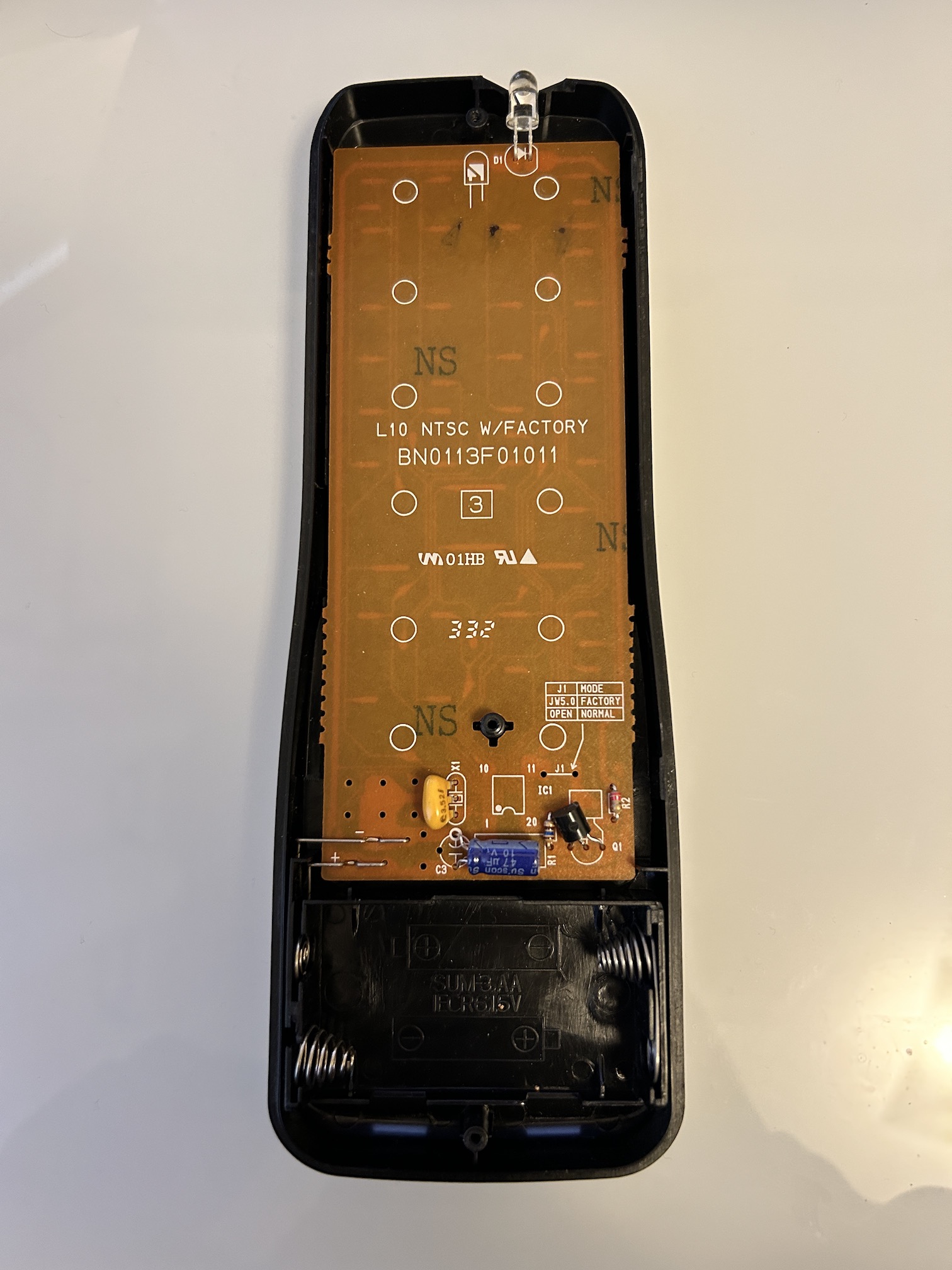
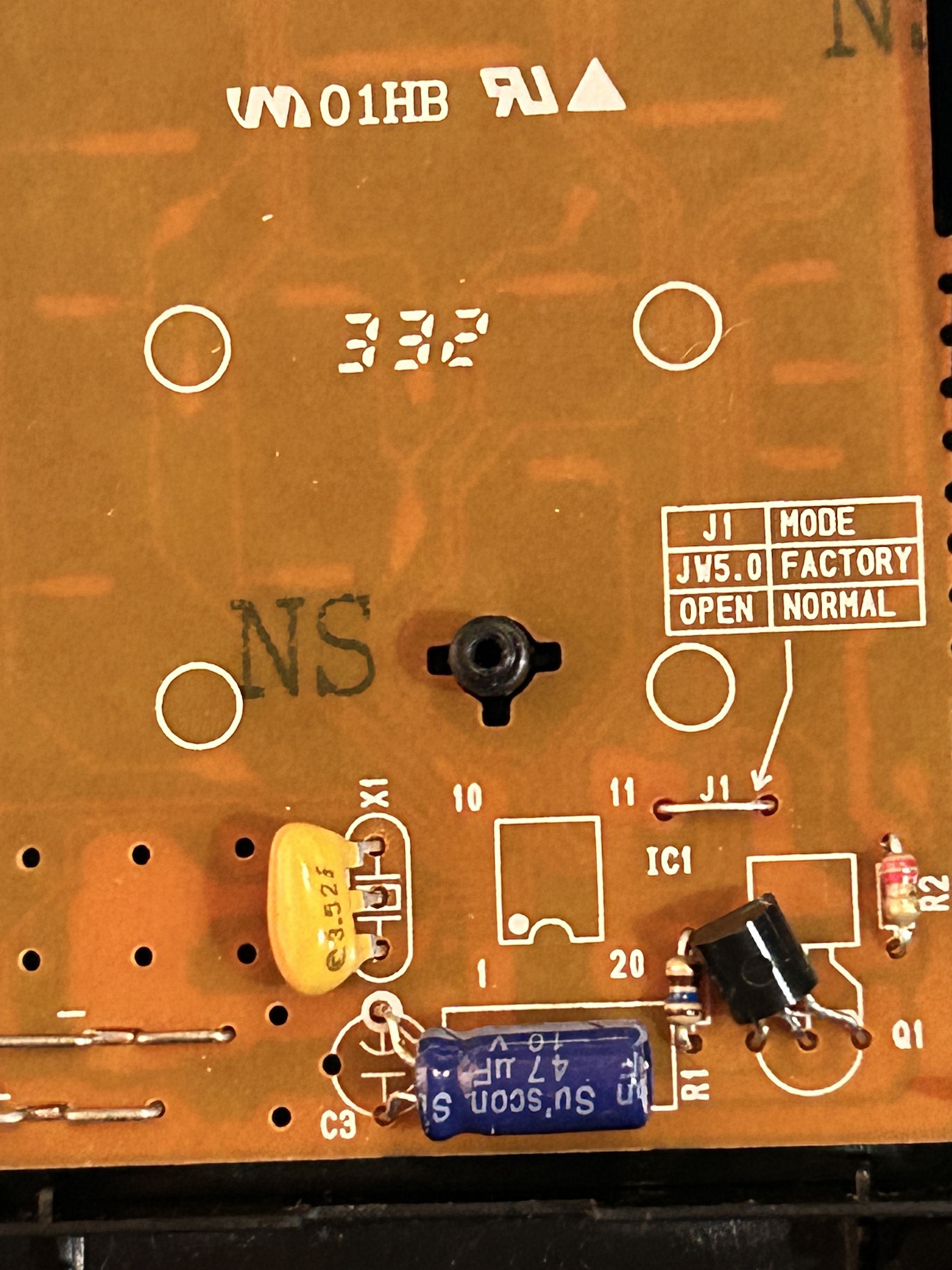
STEP 6: Service Menu
To access the service menu on this device, you'll need the OEM remote and perform a minor modification by shorting Jumper J1. Follow these steps:
- There are 3 screws holding the OEM remote together. Once the screws are removed the back easily detaches.
- Take the remote's PCB outside, and use a wire to create a short for Jumper J1.
Once the modification is made, use the below buttons to adjust the horizontal shift.
- Press the power button on the TV (Remote power button won't work)
- SLEEP: Enter service mode
- POWER: Exit service mode
- H-POS: Press 8 on remote. Use CH +/- to adjust. Had to go from 10 to 12.
You can use a universal remote to control this Sylvania tv. However, you will need an OEM remote to get into the service menu.
I was able to use an RCA 503BR remote with 0171 code to control this set.
Pictures
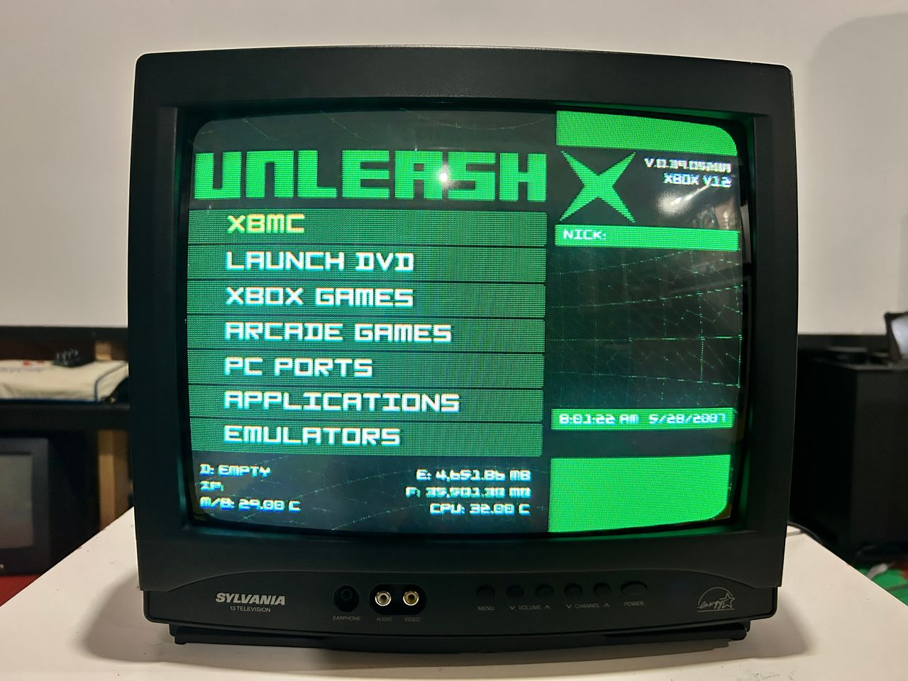
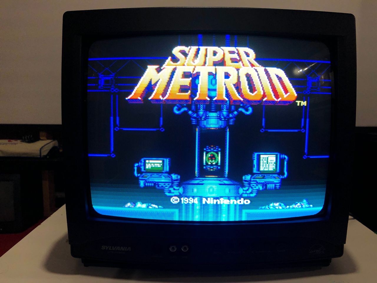
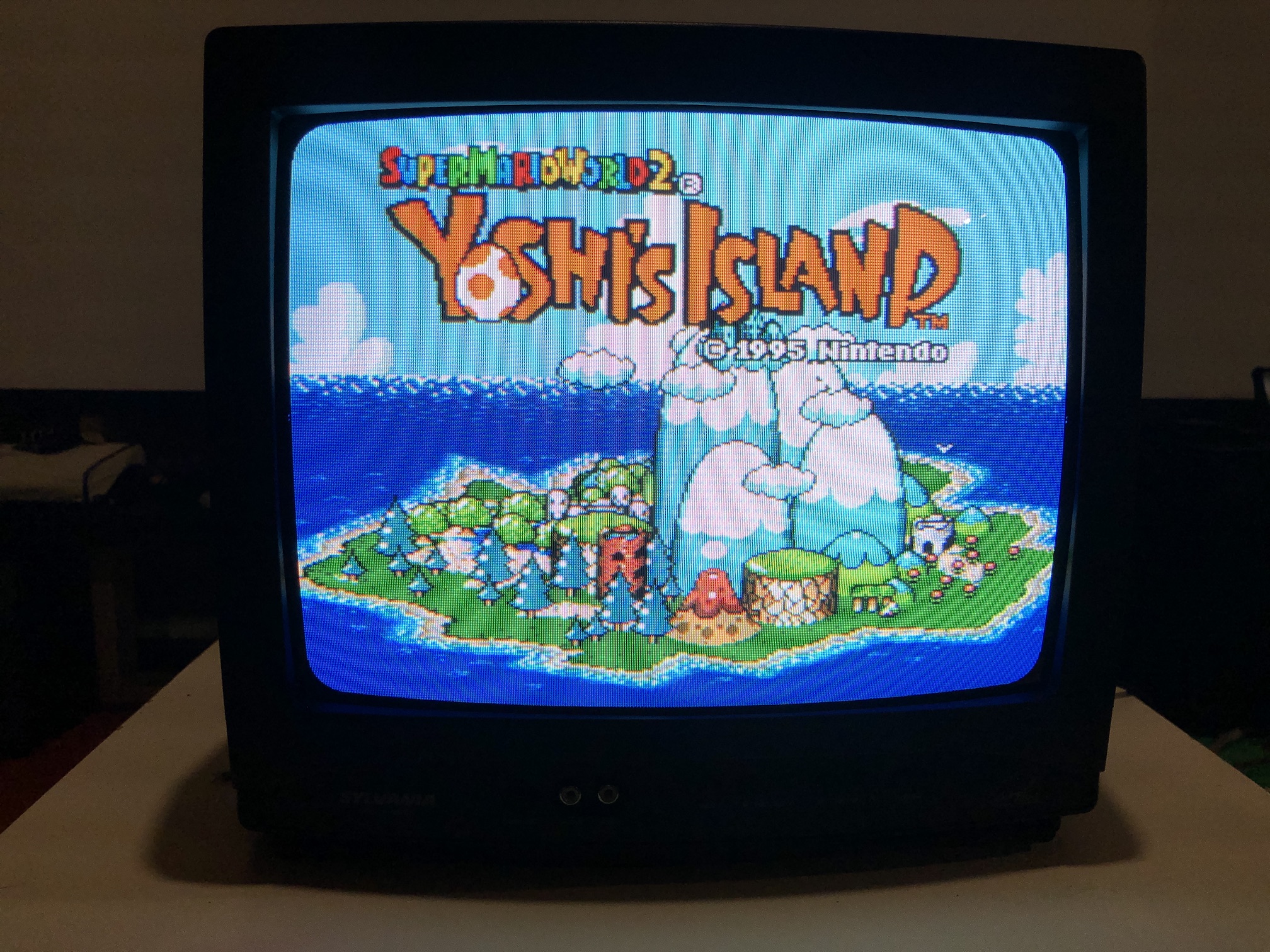
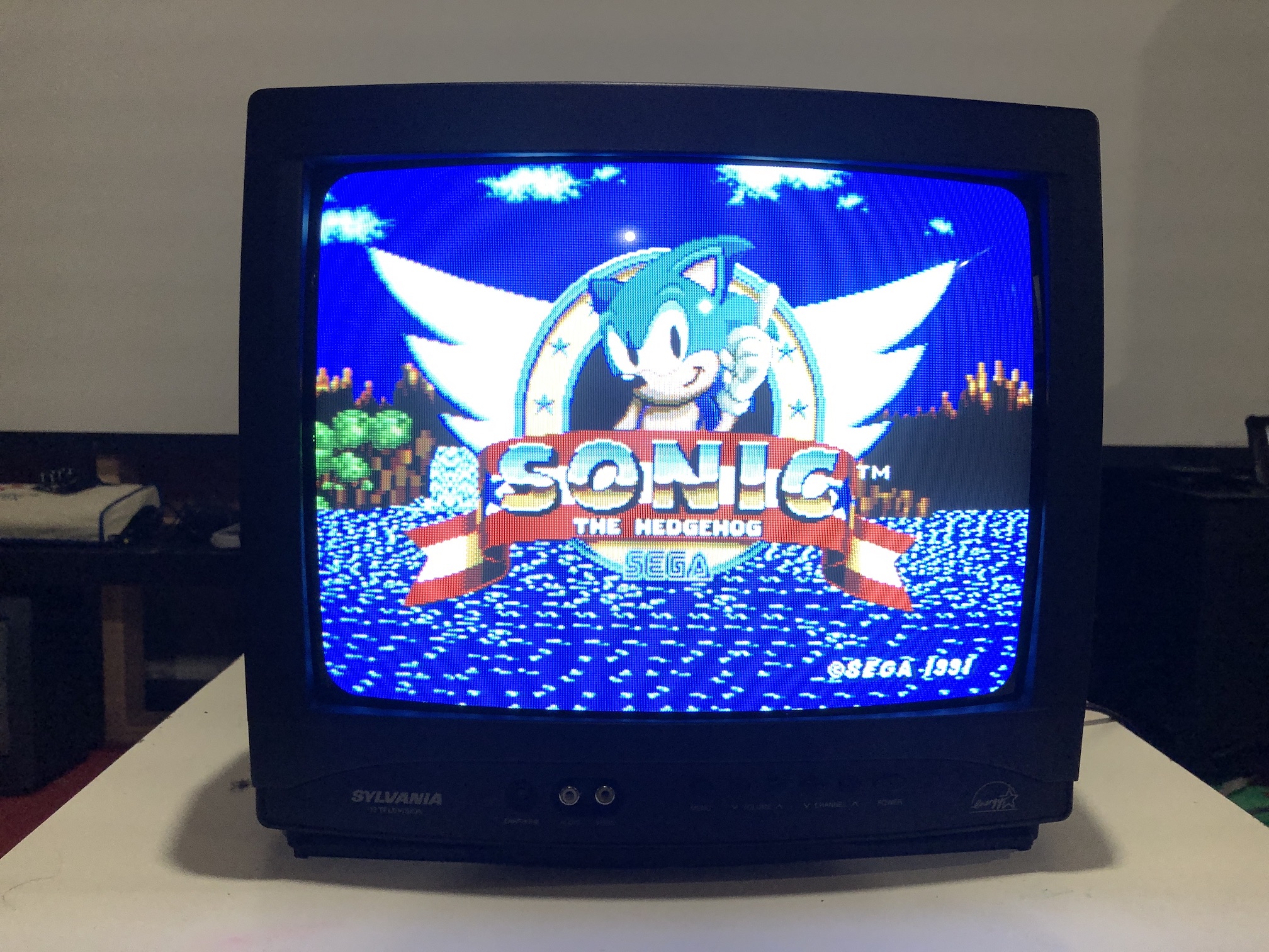
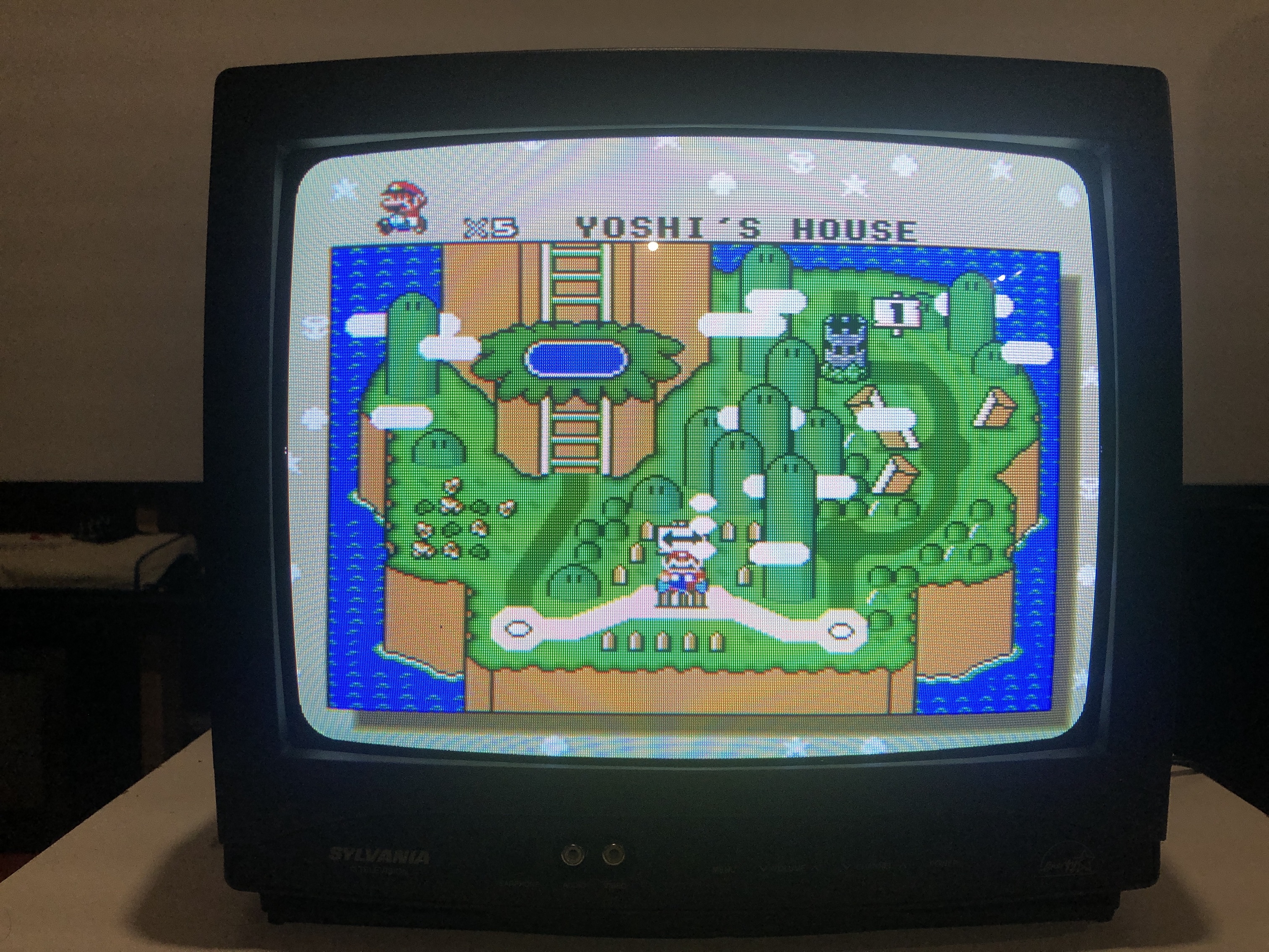
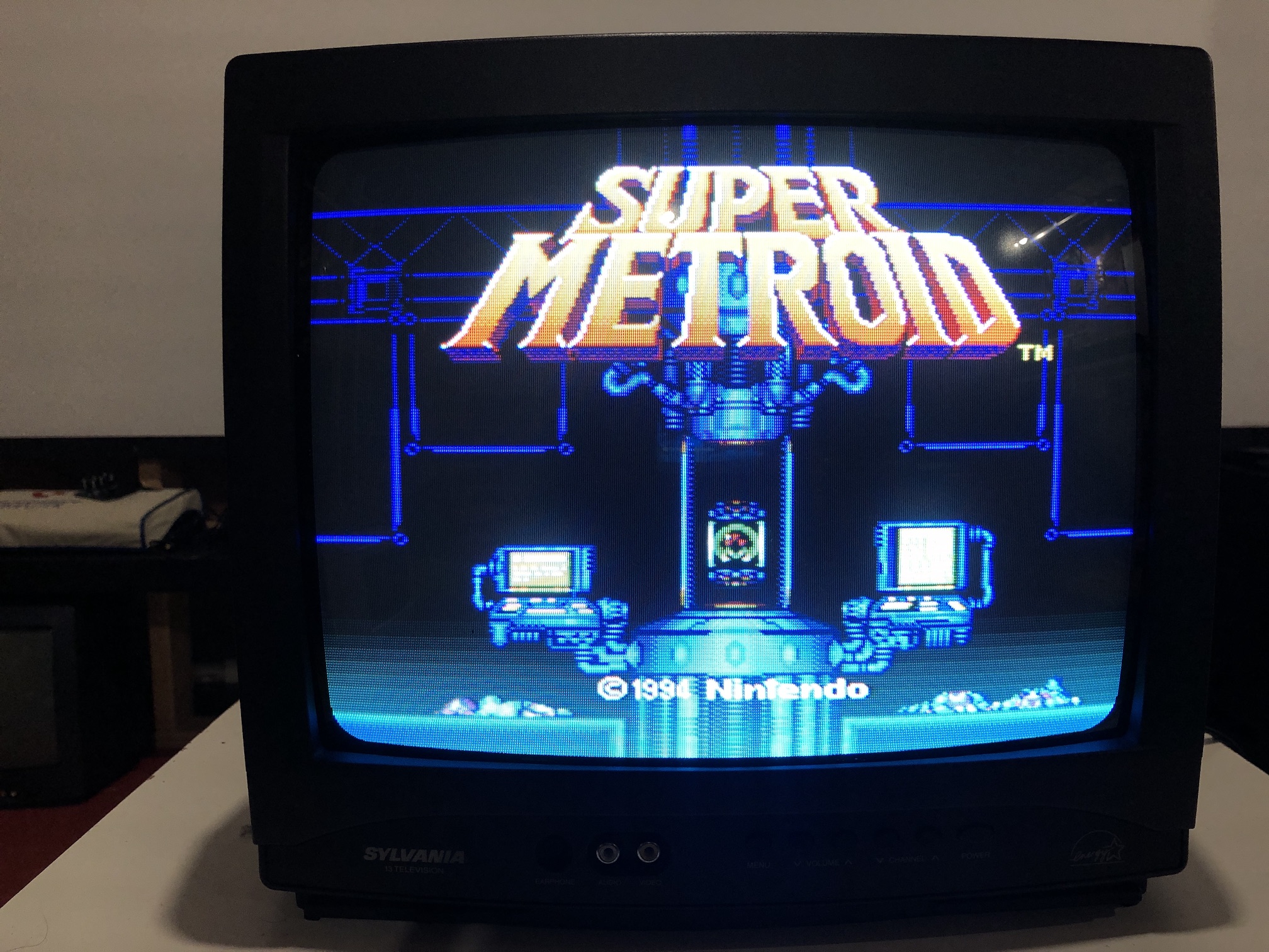
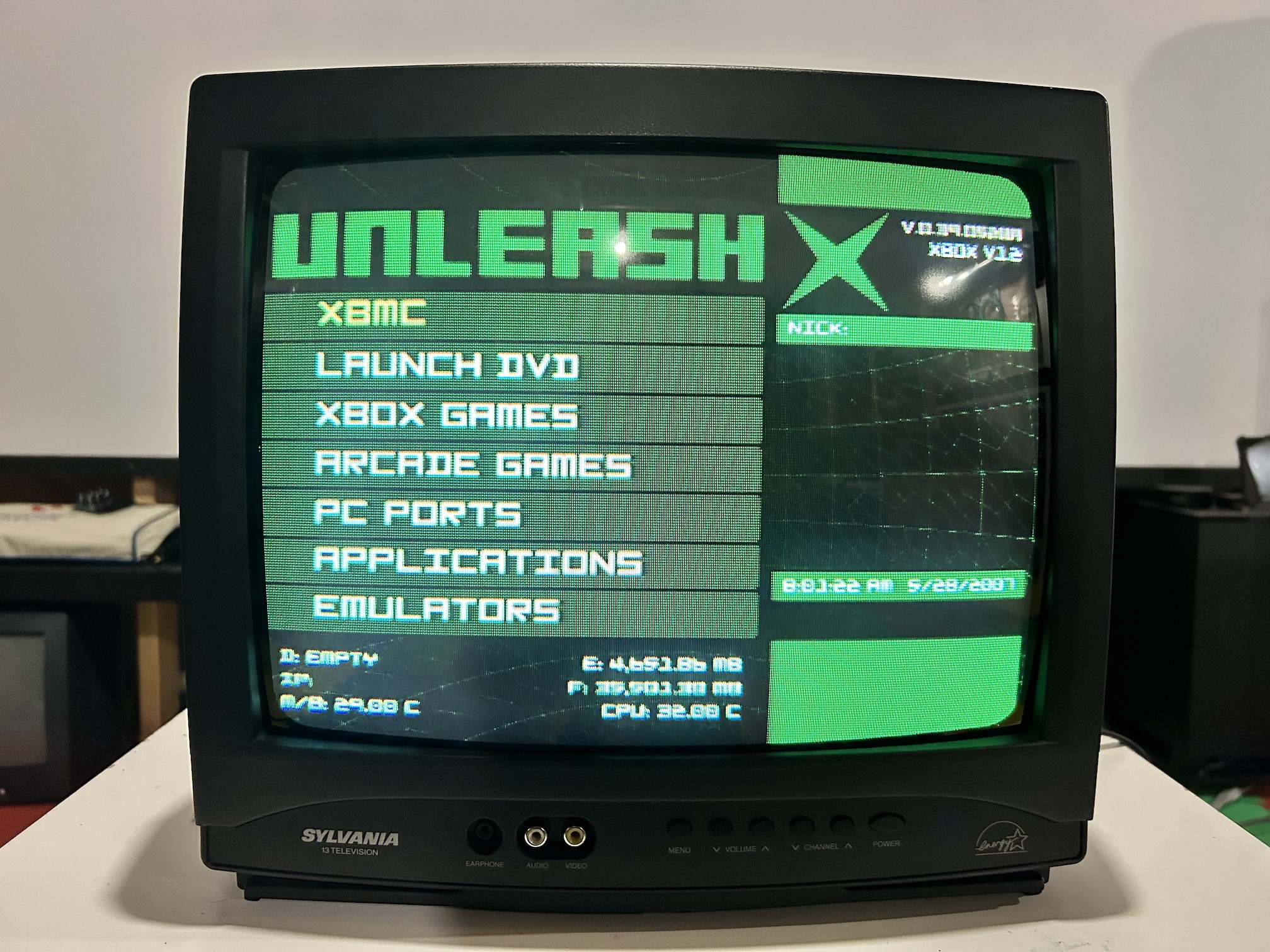
Games
Patterns
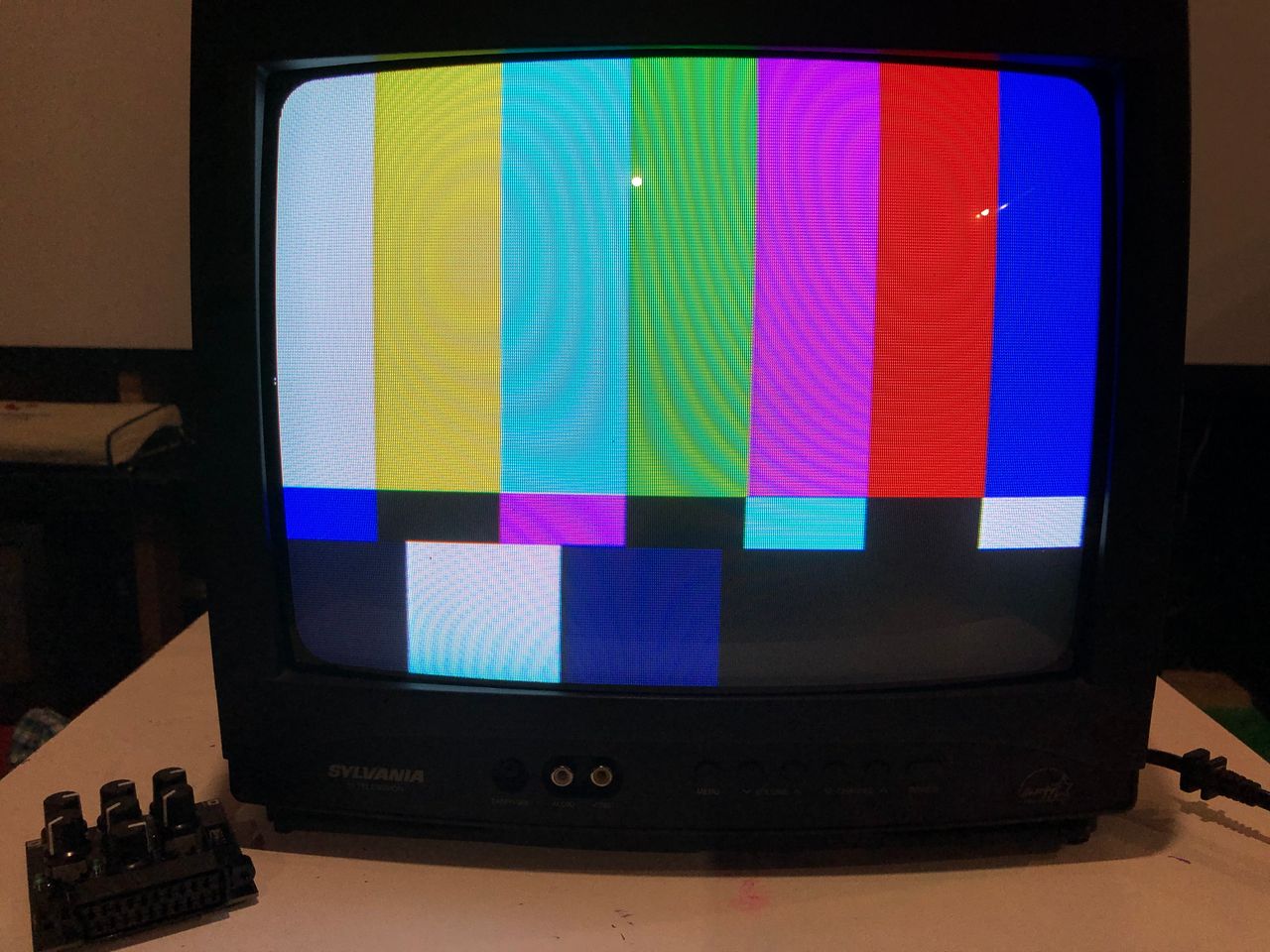
240p pattern - SMPTE 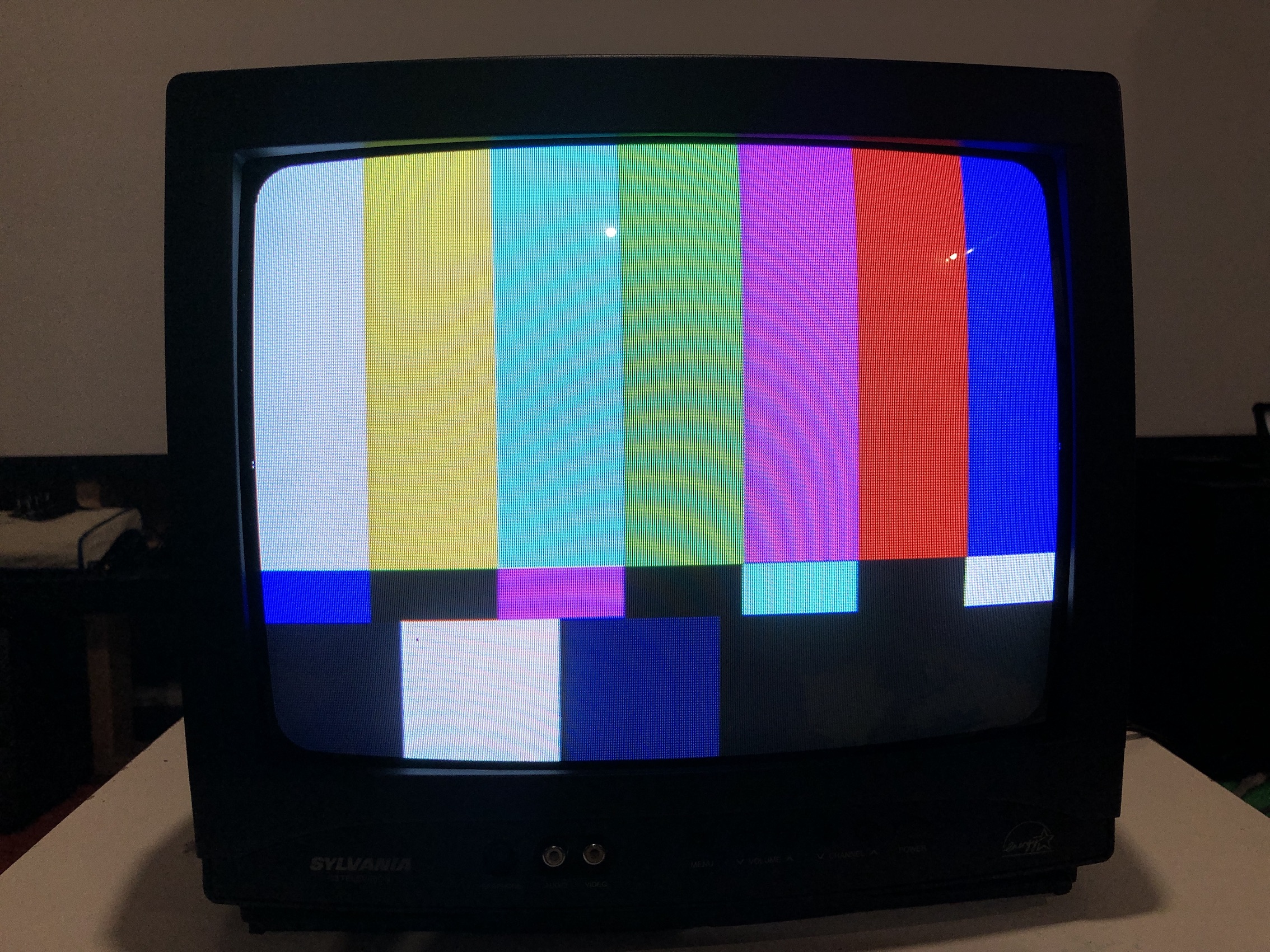
240p pattern - Convergence 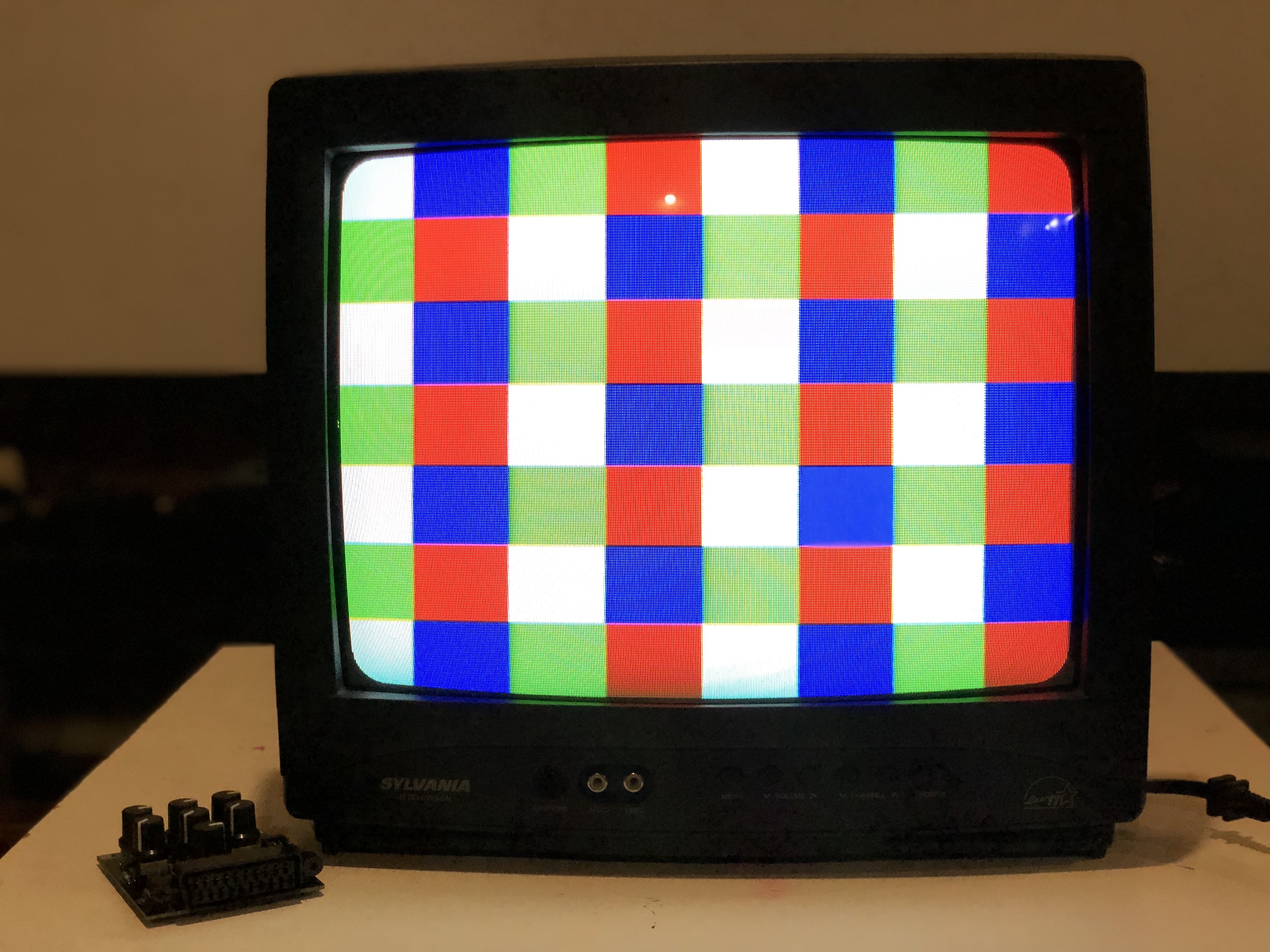
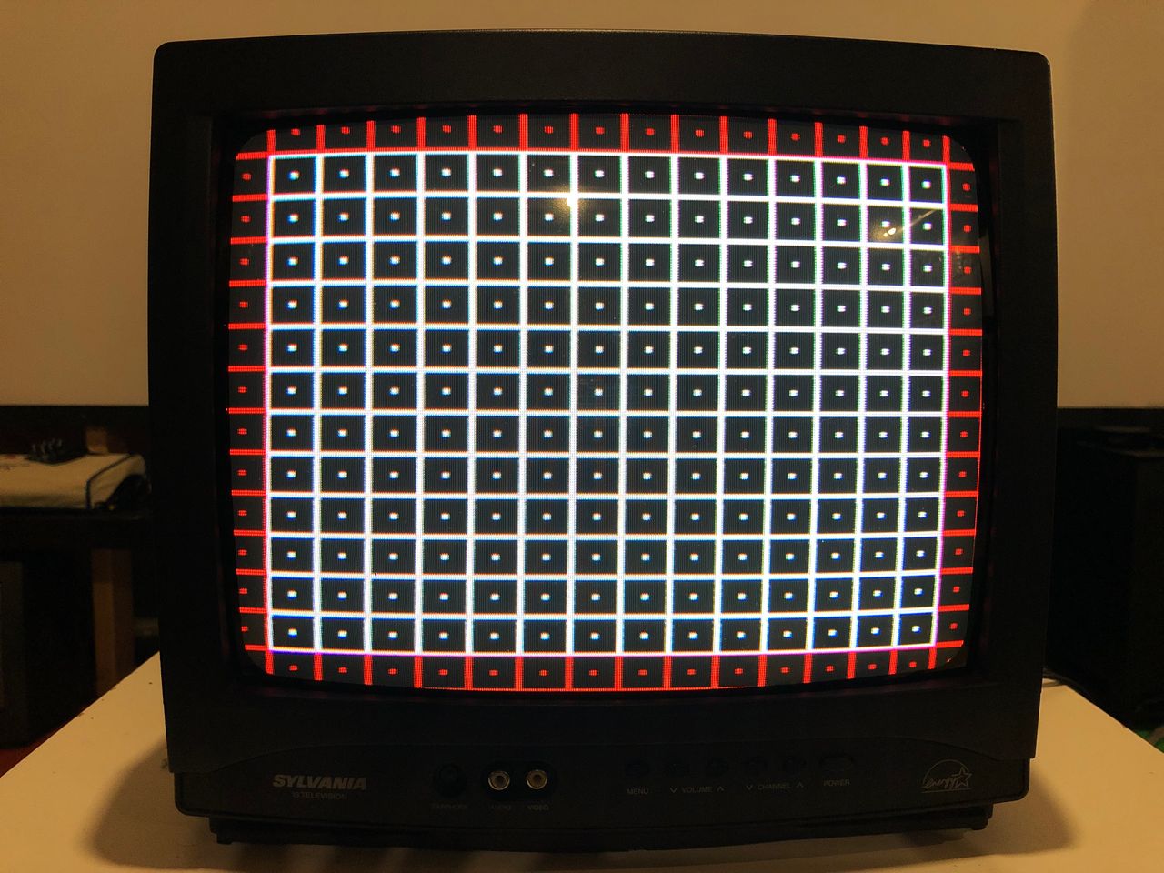
240p pattern - grid 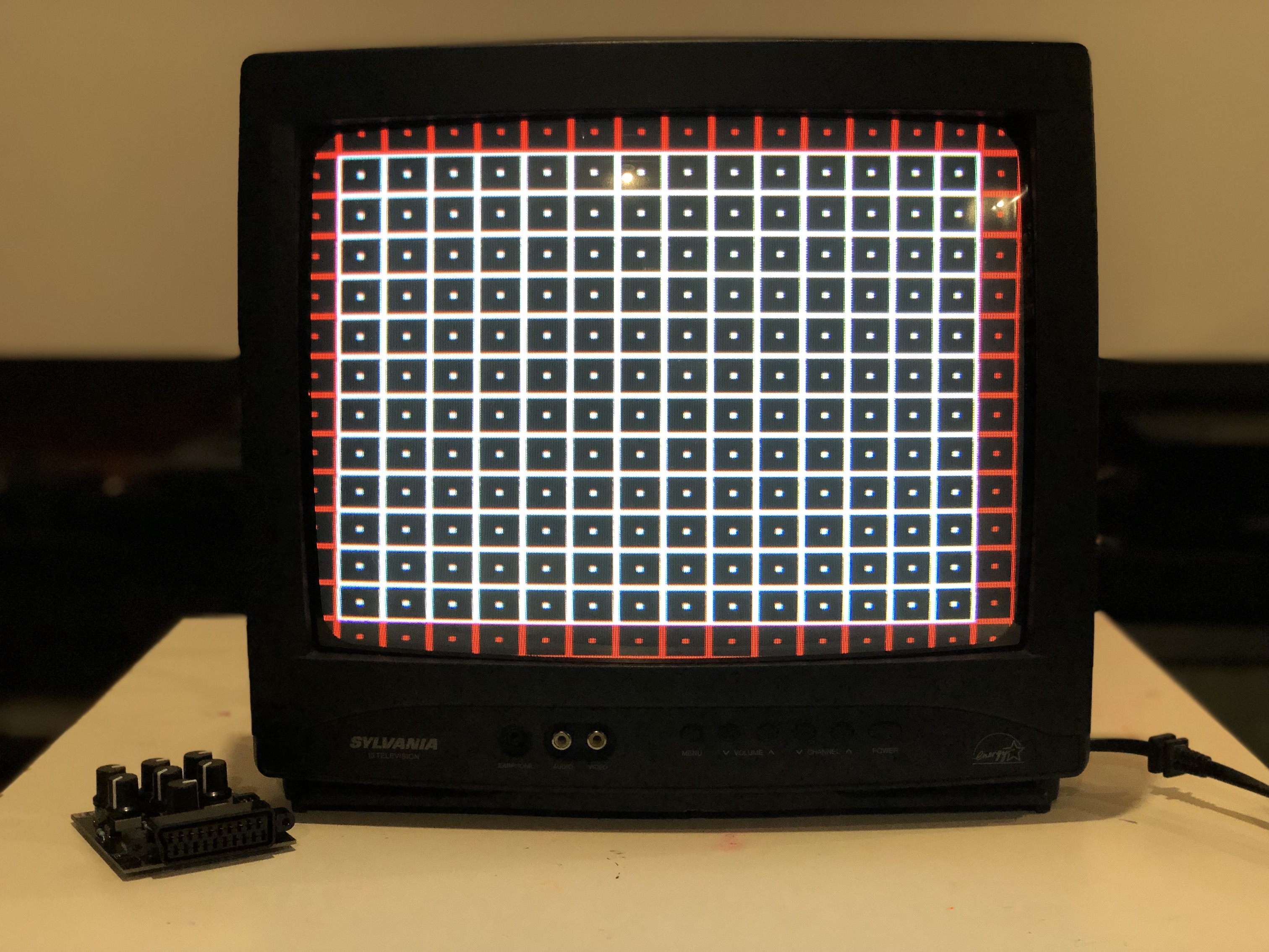
240p pattern - after horizontal shift 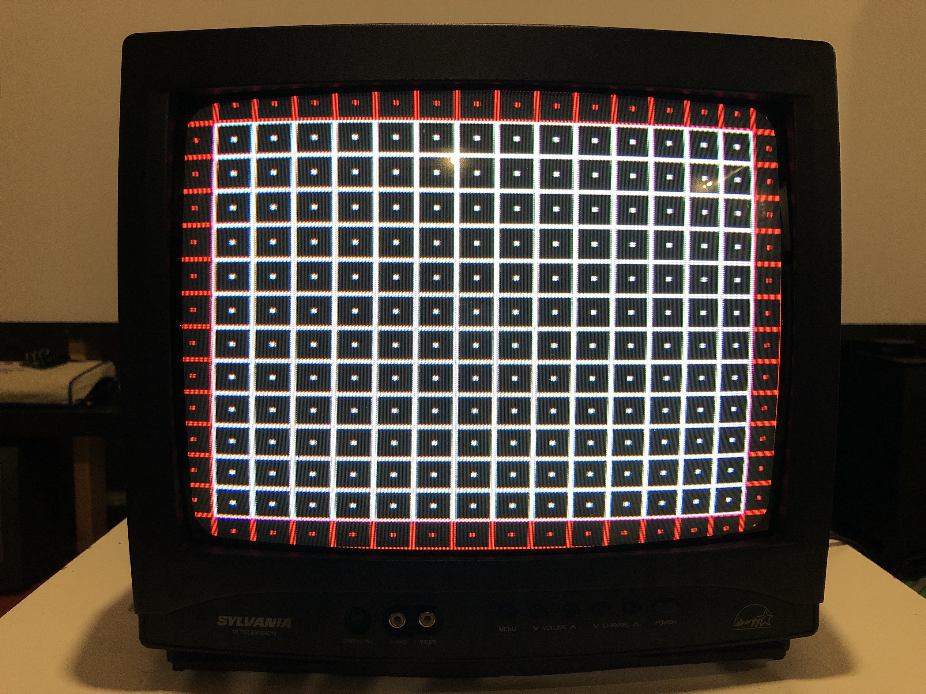
General
Tube 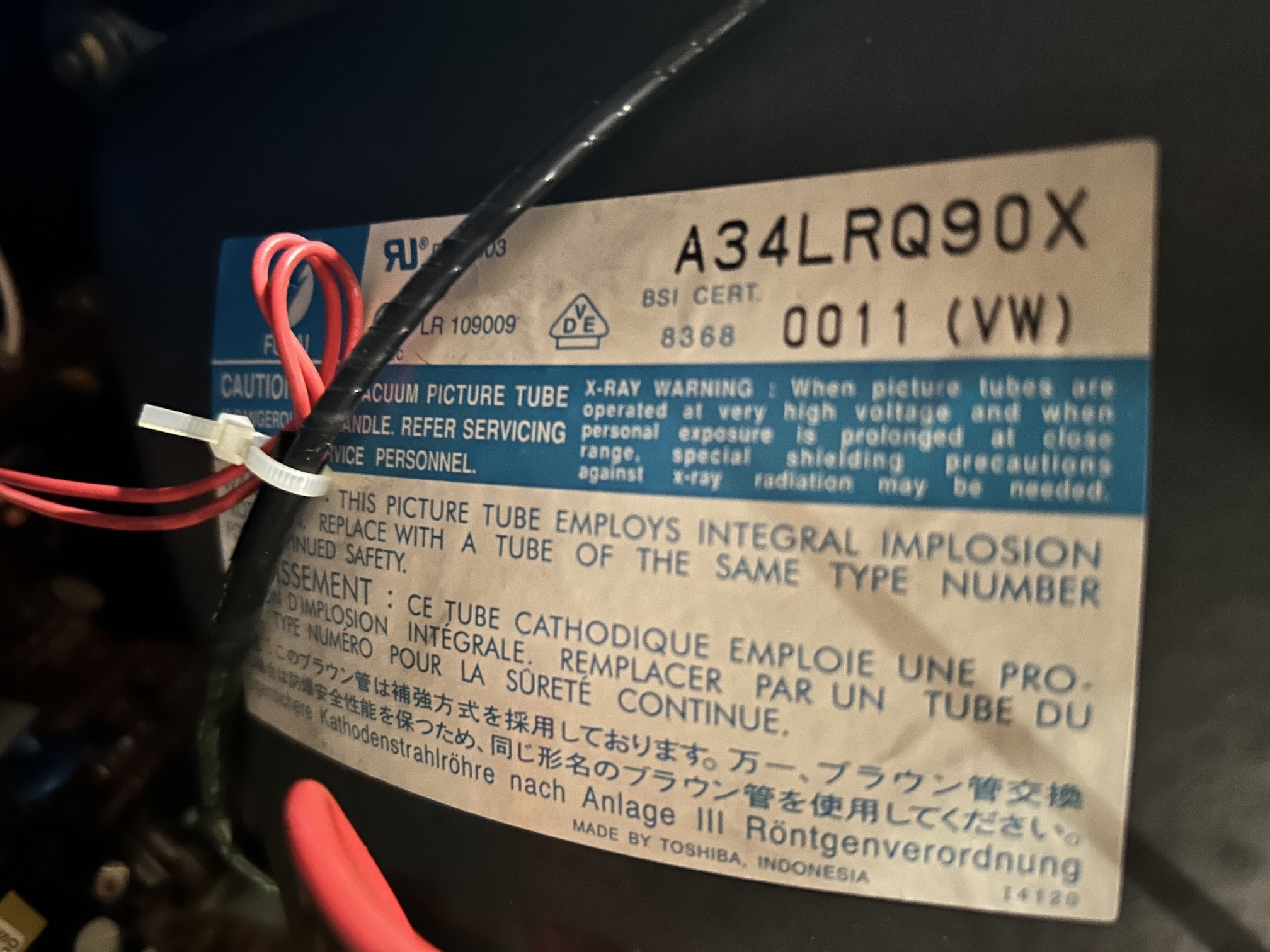
Back Label 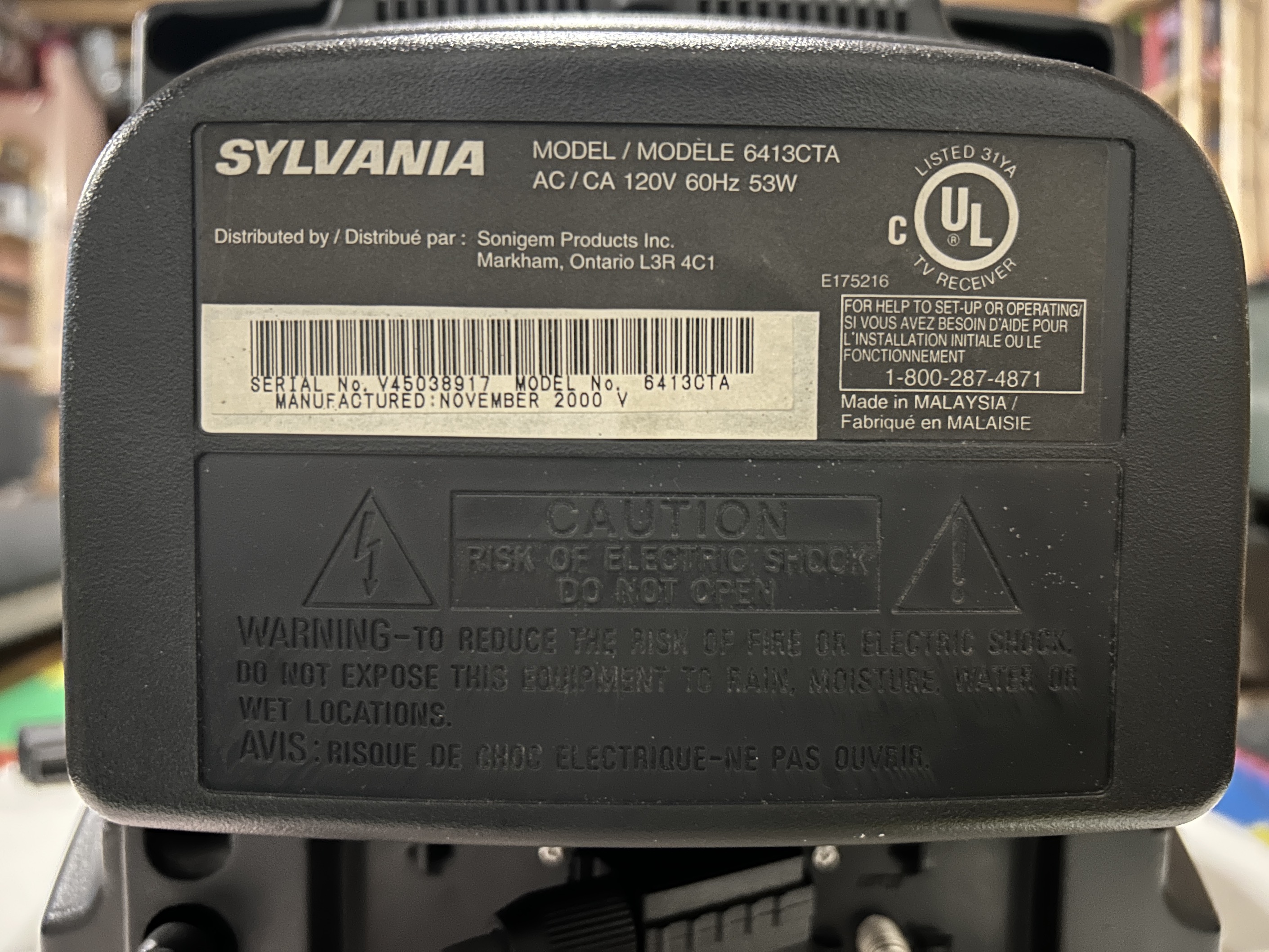
Flyback 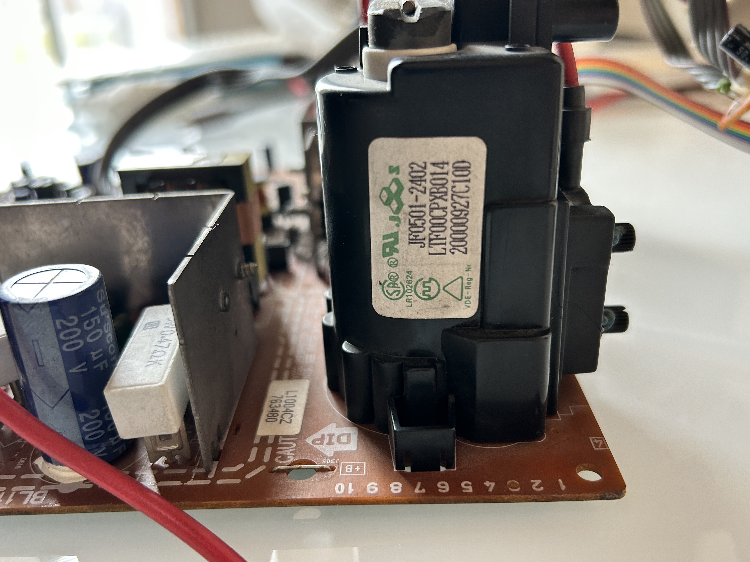
Component side with several caps replaced (marked with red dots) 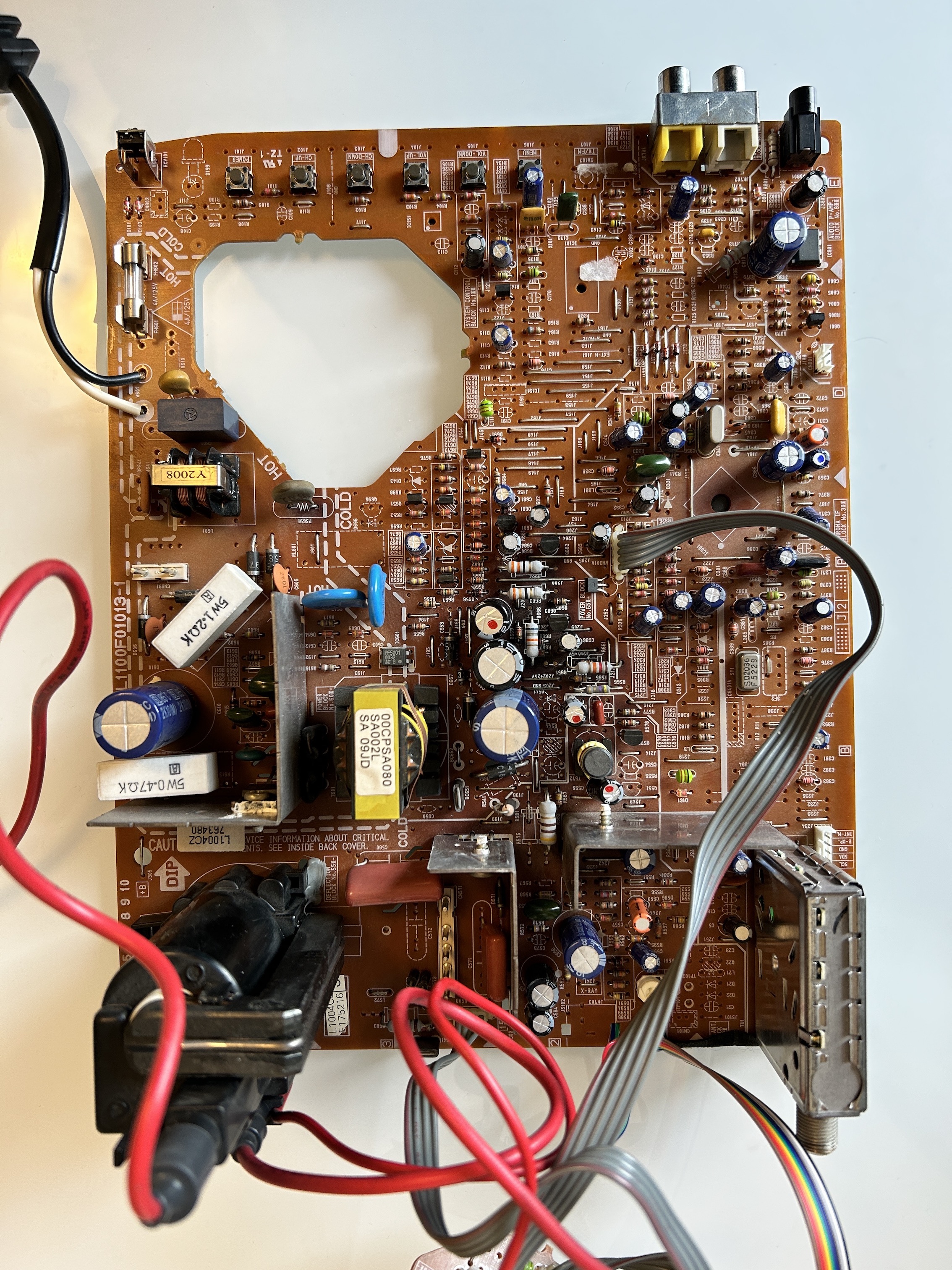
Pictures
Photos by Sunthar
Reference Photos