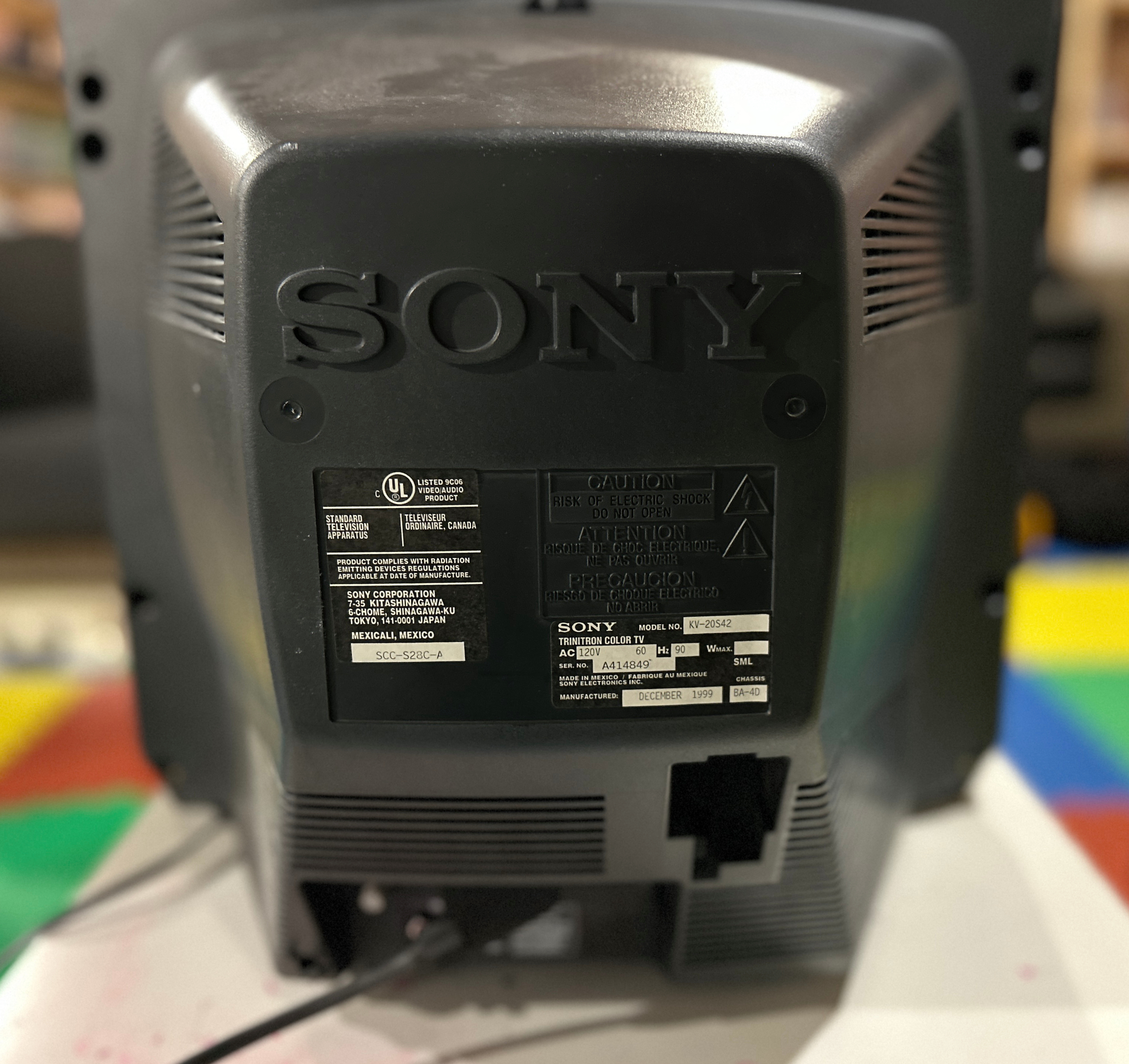
Sony (BA-4D) KV-20S42
Sony (BA-4D) KV-20S42 CRT RGB mod
The Sony KV-20S42 is renowned for its 20-inch viewable size and classic 4:3 aspect ratio, making it an excellent choice for retro gaming and vintage media enthusiasts. Manufactured in Mexico, this model features the iconic Sony Trinitron tube, known for its vibrant color reproduction and sharp image quality.
Equipped with the BA-4D chassis, the KV-20S42 supports RGB input via a mux method and allows for component input through direct injection, providing flexibility for various connectivity options.
The display's chroma is powered by CXA2133S/CXA2133BS chips. With its robust build and modding potential, the Sony KV-20S42 stands out as a reliable choice for those looking to enjoy classic video games and media in their original format.
View full CRT details and more mod examples →
The RGB mod for the Sony KV-20S42 is fairly simple and makes a noticeable improvement on this composite-only set. Additionally, the KV-20S42 can be modified for component input as well. For this mod, I also decided to permanently enable stereo sound. Interestingly, it's possible to add an S-Video input if you can find the right connector, though I plan to tackle that at a later time. You can also follow this older tutorial which has additional pictures.
Instructions below should also apply to these models:
Contributors
Thank you to everyone who contributed to this guide:
- Sunthar — showcase author
CRT safety
Caution
You can die doing this! So read carefully! CRT TV is not a toy. Do not open a CRT TV. If you don't have any prior knowledge about handling high voltage devices, this guide is not for you. CRT TV contains high enough voltage (20,000+ V) and current to be deadly, even when it is turned off.
Plan of attack
Manuals and Datasheets
- Sony KV-20S42 Service Manual
- Sony KV-20S42 Service Manual
- Sony CXA2061S Datasheet (Jungle)
- M37273MF-252SP Datasheet (OSD) — Available for Pro Users only. See CRT details for access.
Specs
- Manufactured: Mexico (1999)
- Chassis: BA-4D
- Tube: Sony Trinitron A51LML50X
- Jungle Chip: Sony CXA2061S
- OSD Chip: M37273MF-252SP
- Screen Size: 20"
RGB mux diagram
Prepare the mux diagram. If you are building your own circuit, this diagram should help.
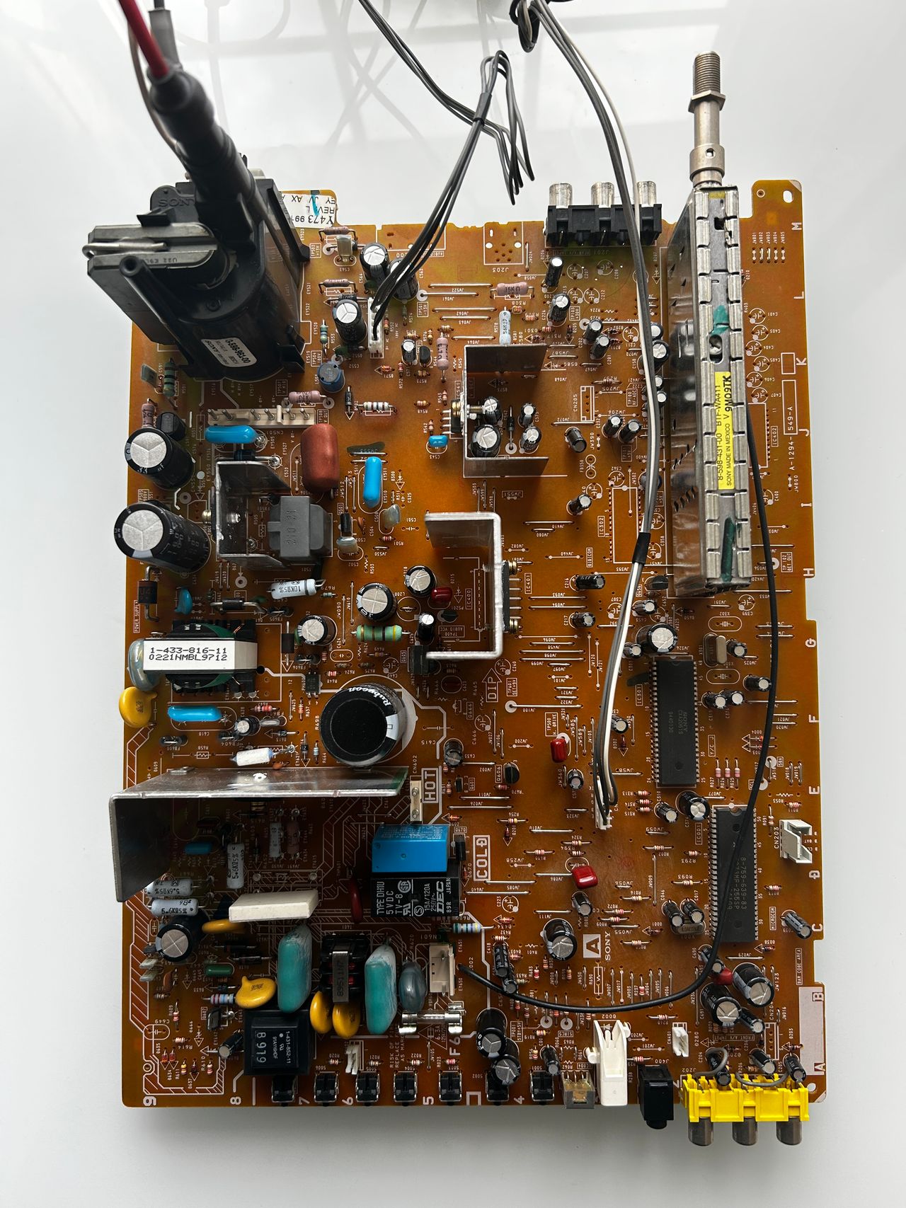
Performing the mod
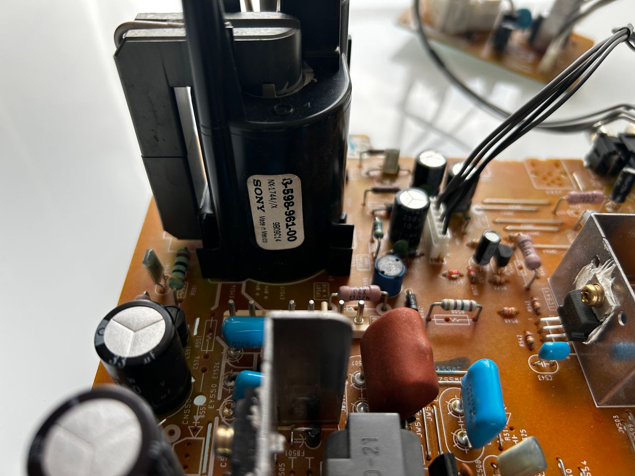
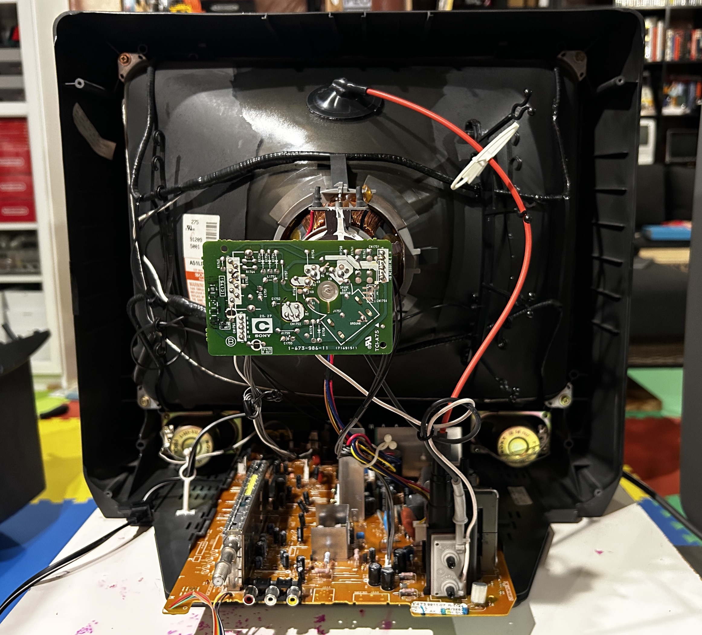
Now that you roughly know what needs to be done, prepare for the mod. Place the board on a comfortable place. Make sure you are not putting pressure on the flyback or other components. Taking out the chassis is fairly straight forward on this CRT.

There are few wires that needs to be disconnected.
- Degauss wire
- Power wire
- Ground wire attached to the neck board
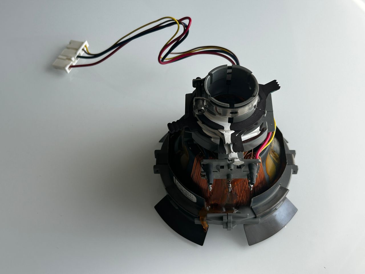
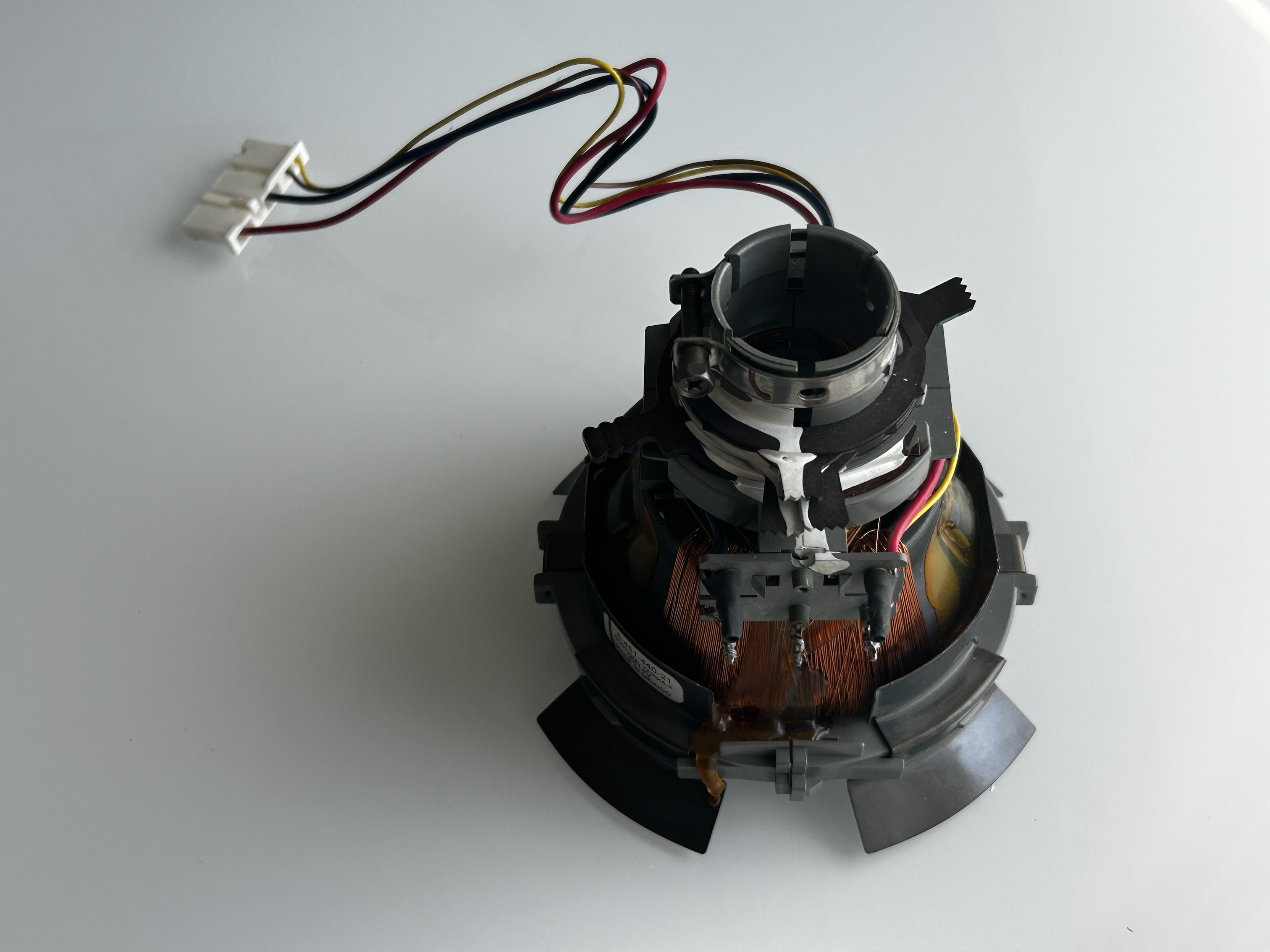
- Yoke deflection coil wire
- Anode wire (this is the one with the rubber cap)
- Left and right audio wires
Please remember that wires 1-5 are critical for the CRT to function and should not be omitted. Having any of these wires disconnected while powering up can damage the board and can have adverse effects.
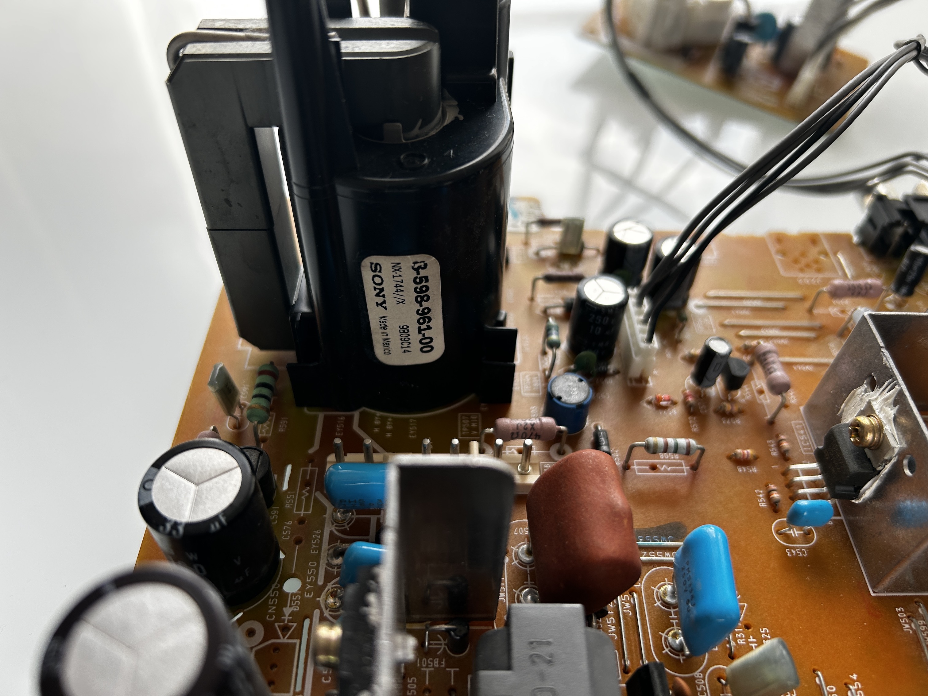
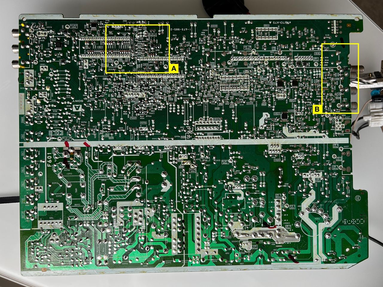
Sometimes it can be overwhelming to see a large chassis. But, we are primarily going to focus on two areas.
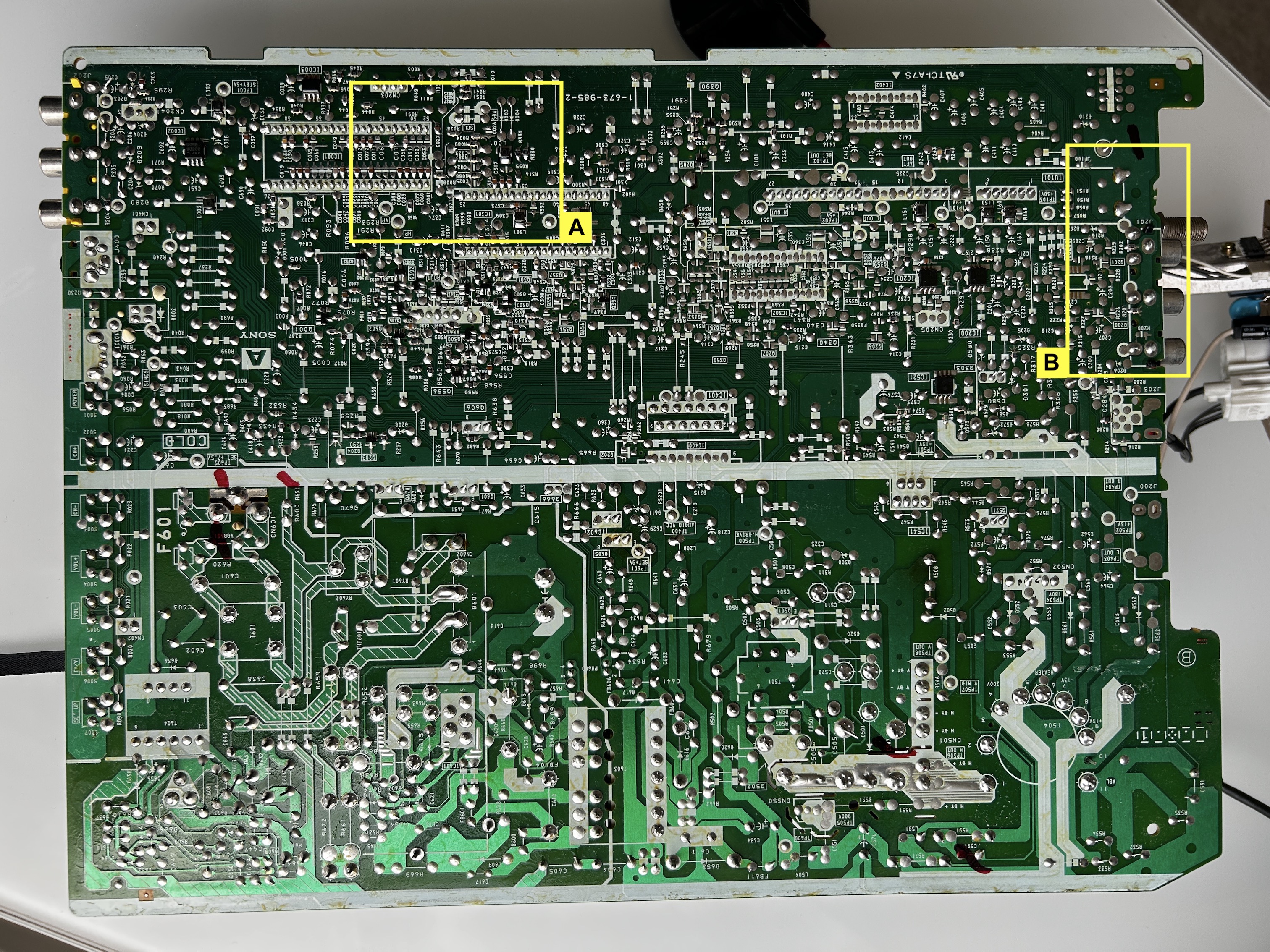
- Area A: This is where we are going to remove resistors and attach the R, G, B and blanking wires
- Area B: This is where we are going to connect composite, audio L, R and ground wires
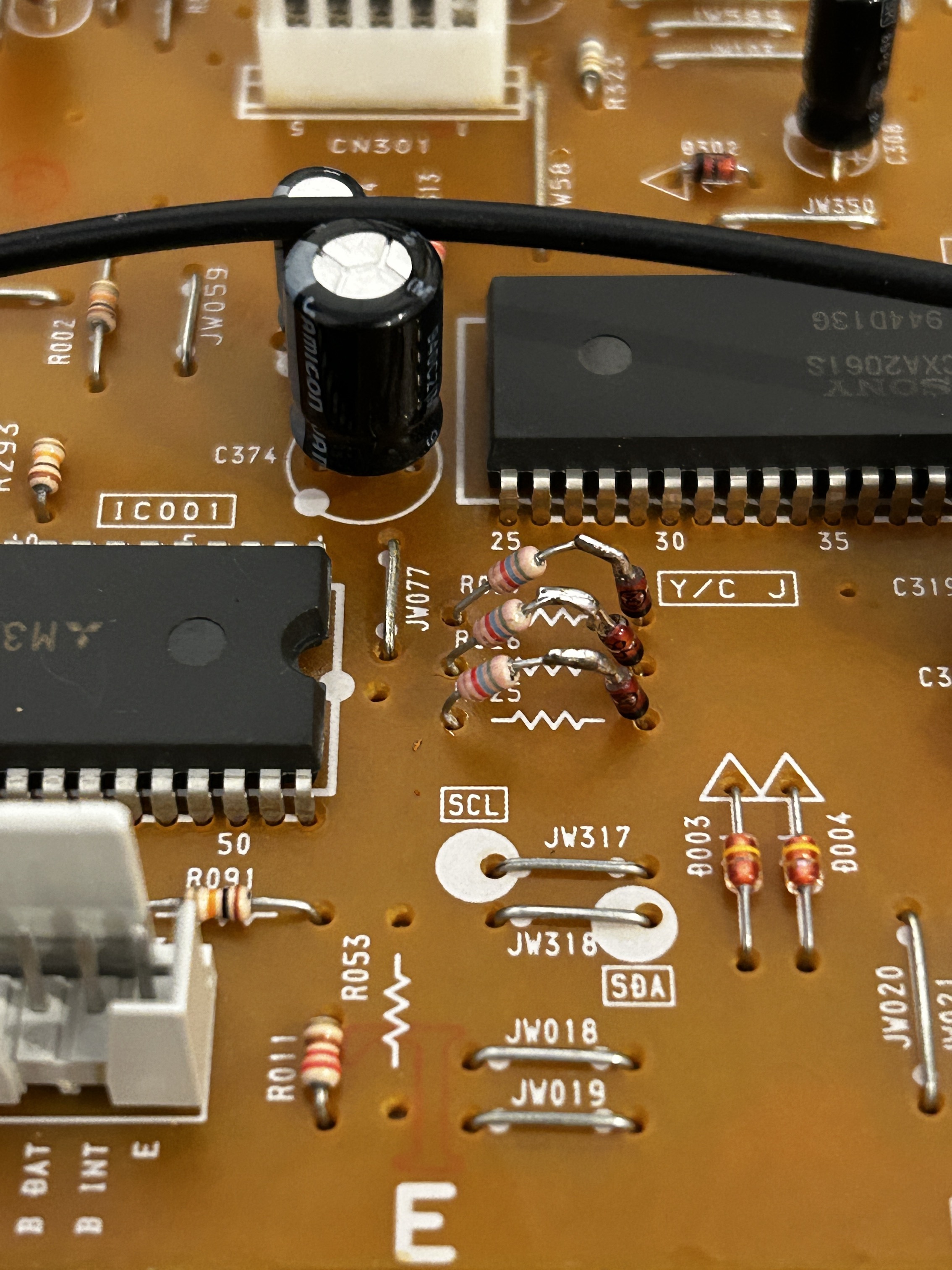
STEP 1: Add RGB inline diodes
I recommend using this method for all KV-20S42 mods to minimize interference. You'll need to lift one side of resistors R025, R026, and R027, and add diodes. The side of the resistors you lift and the direction of the diodes are crucial. If done incorrectly, the OSD will not function. Be sure to follow the instructions and pictures provided carefully.
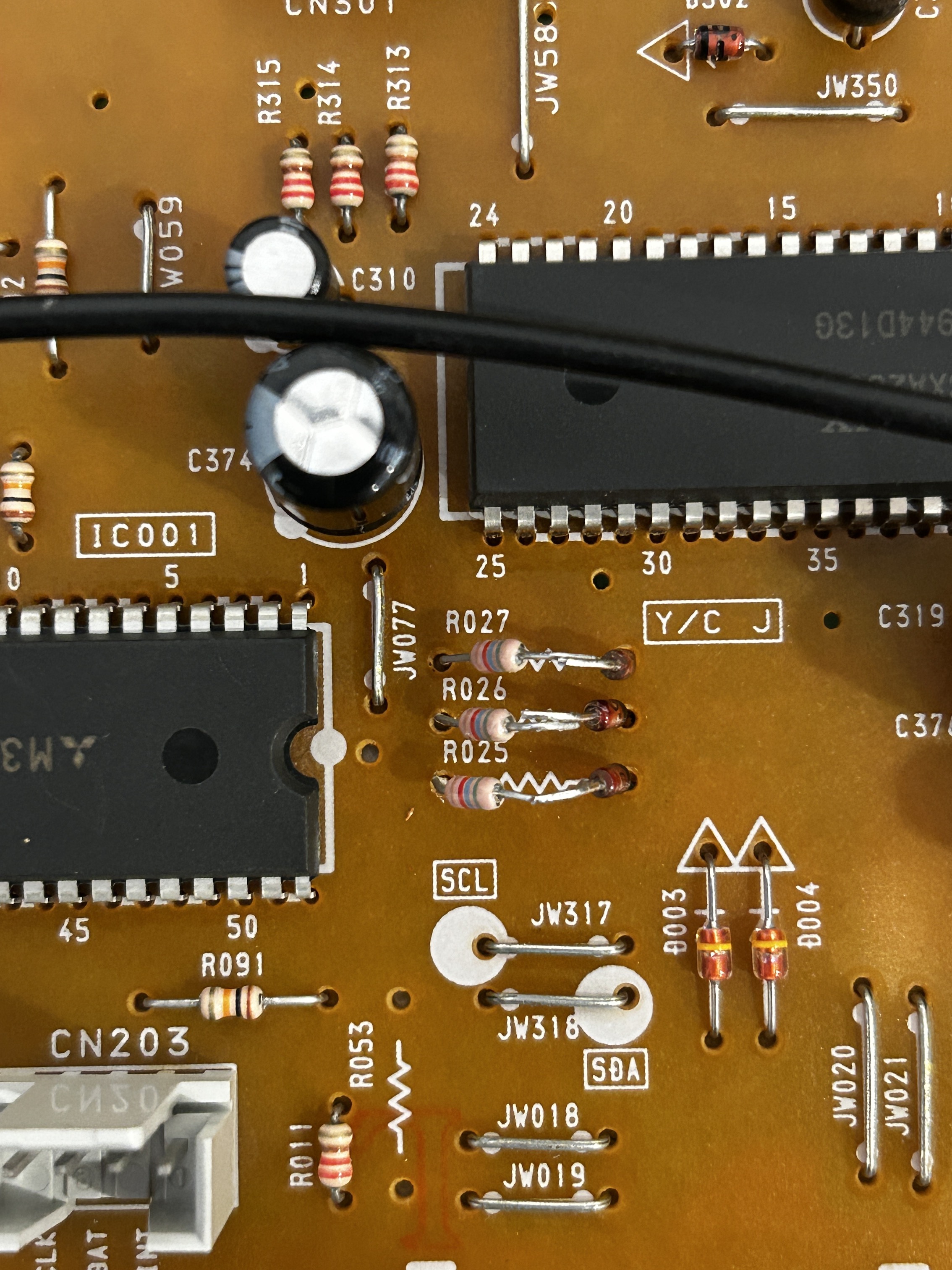
Also, adding didoes means you will need to use 1KΩ resistors on the RGB mux board.
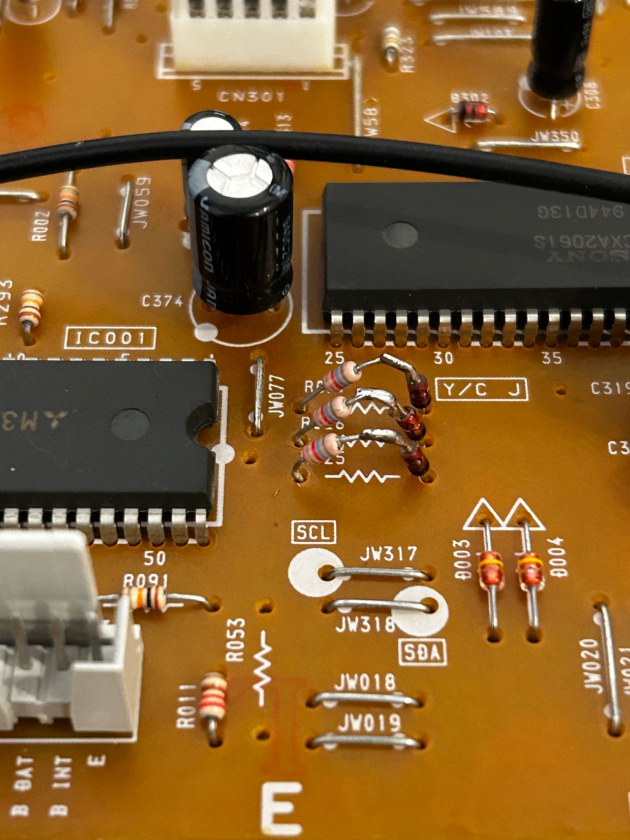
STEP 2: Remove resistors and attach R, G, B wires
Zooming in on Area A before removing the resistors.
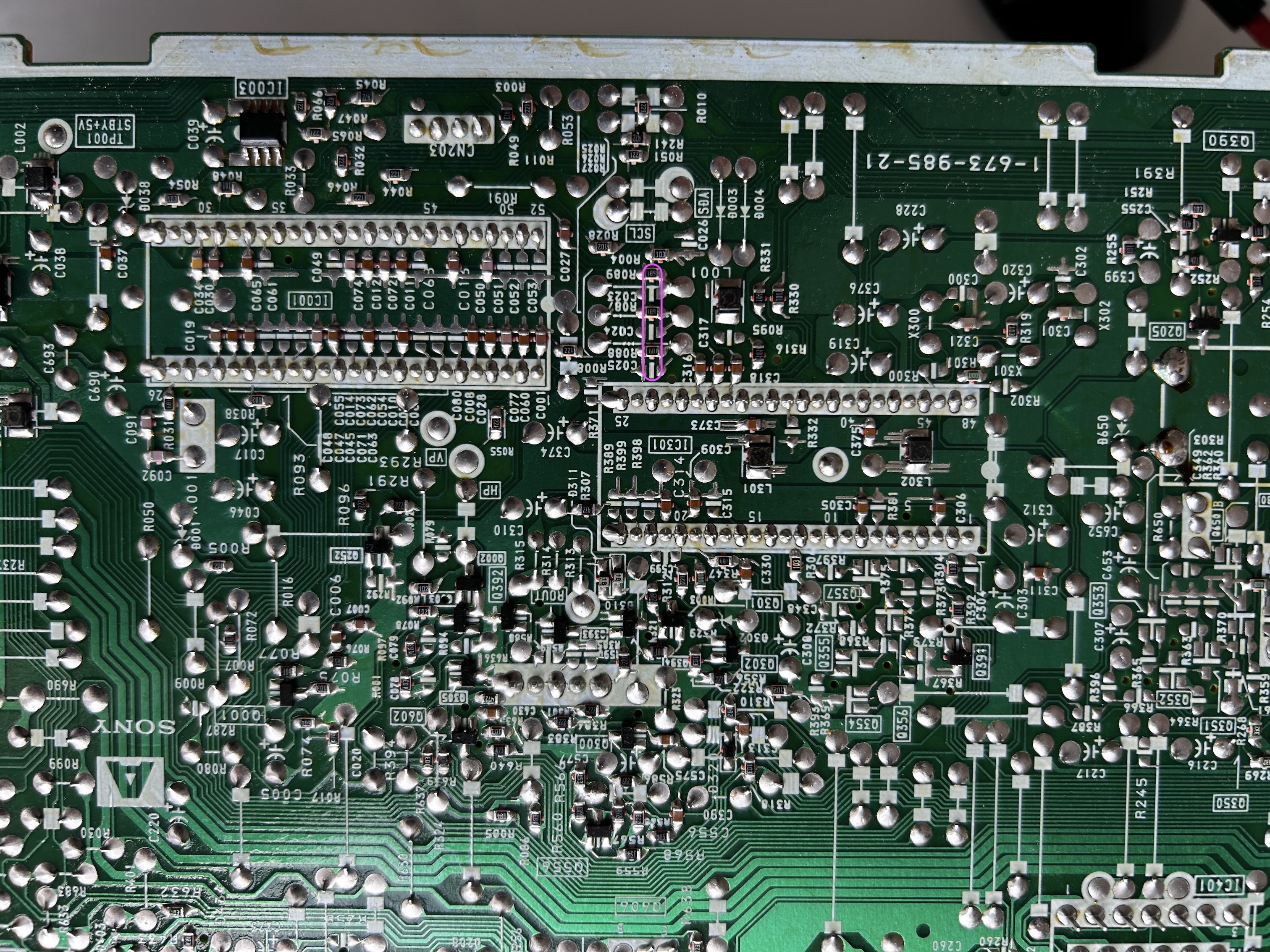
Remove the following components. RGB resistors to the ground. Please always measure and mark them, so that you know you are removing the correct partrs.
- R087 (680Ω) Green ground resistor
- R088 (680Ω) Blue ground resistor
- R089 (680Ω) Red ground resistor
![]()
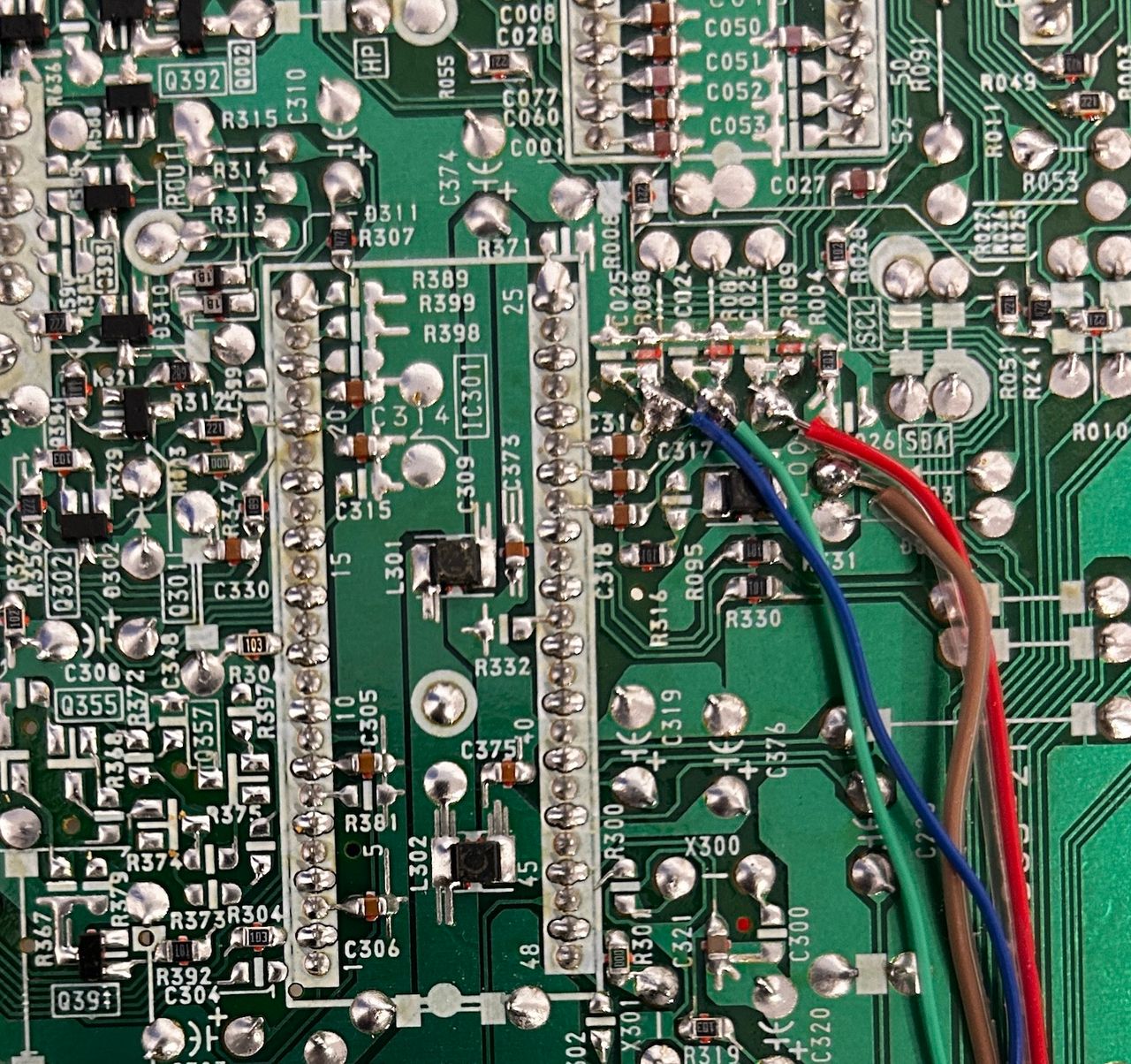
Then attach the R, G, B and blanking wires to the respective legs of the diodes. Wires should be attached to the side closer to the jungle chip.
R, G, B wires are red, green and blue respectively Brown wire here is used for blanking
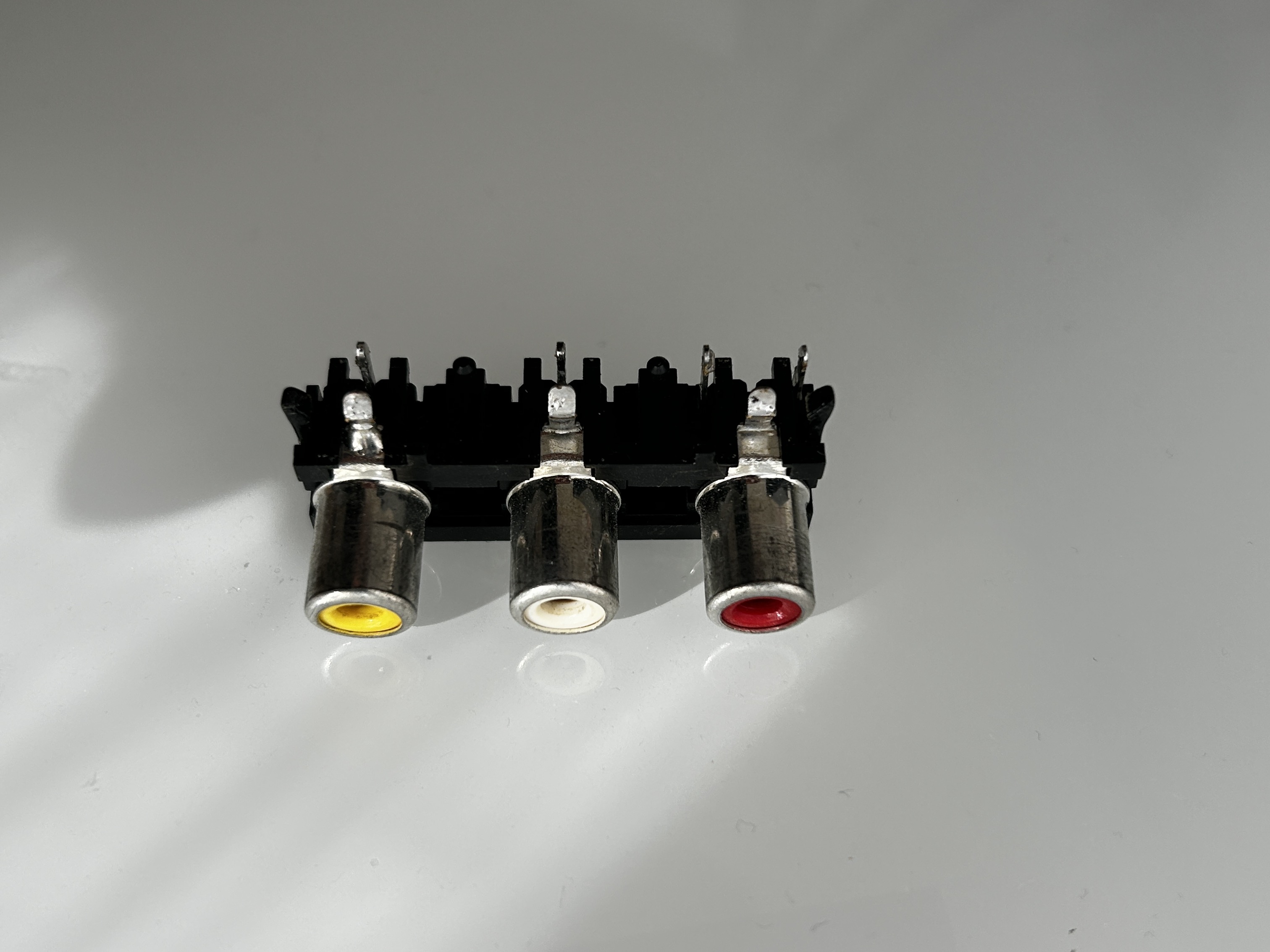
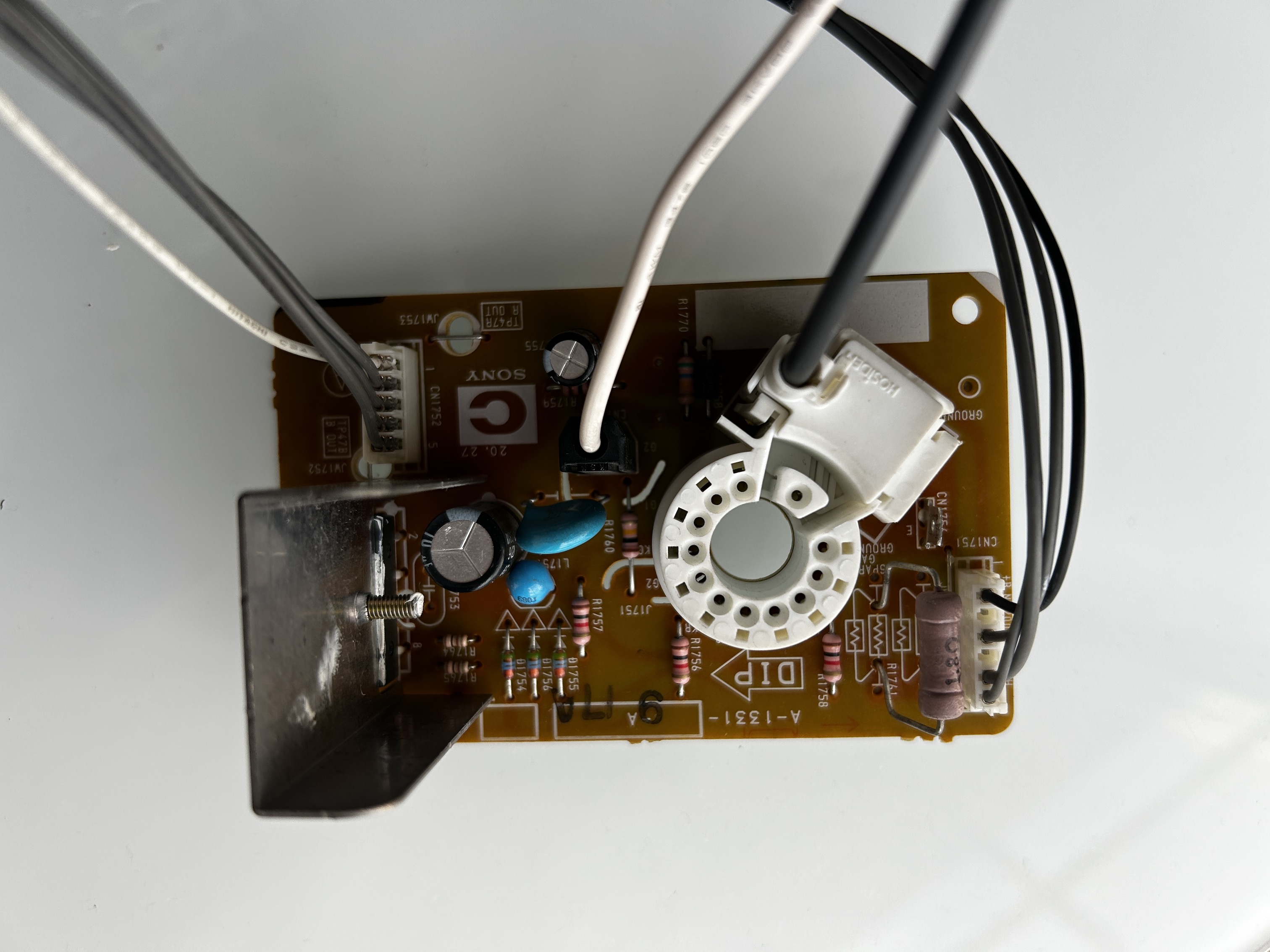
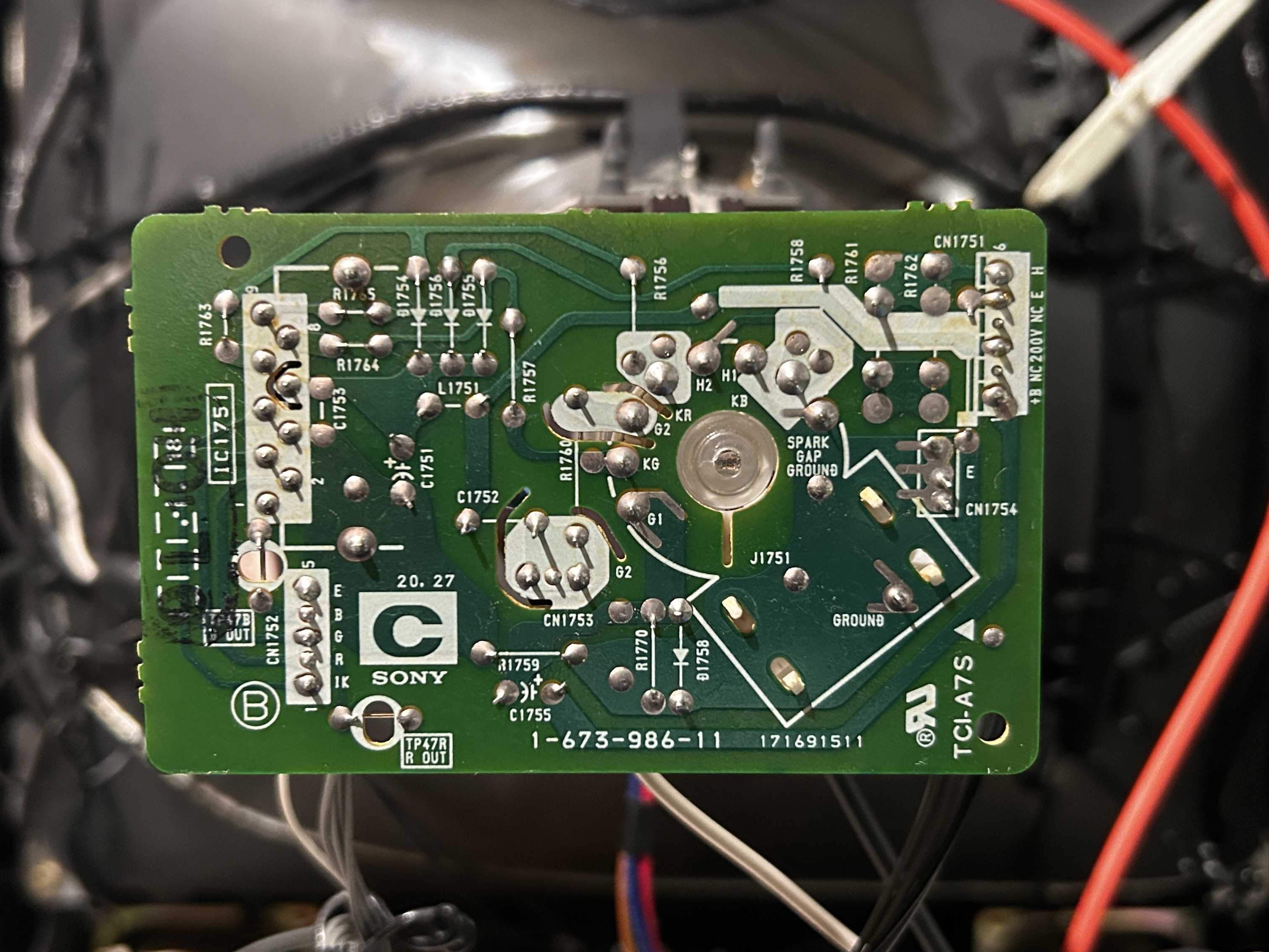
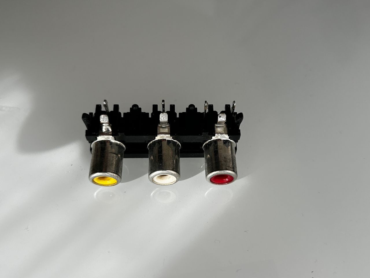
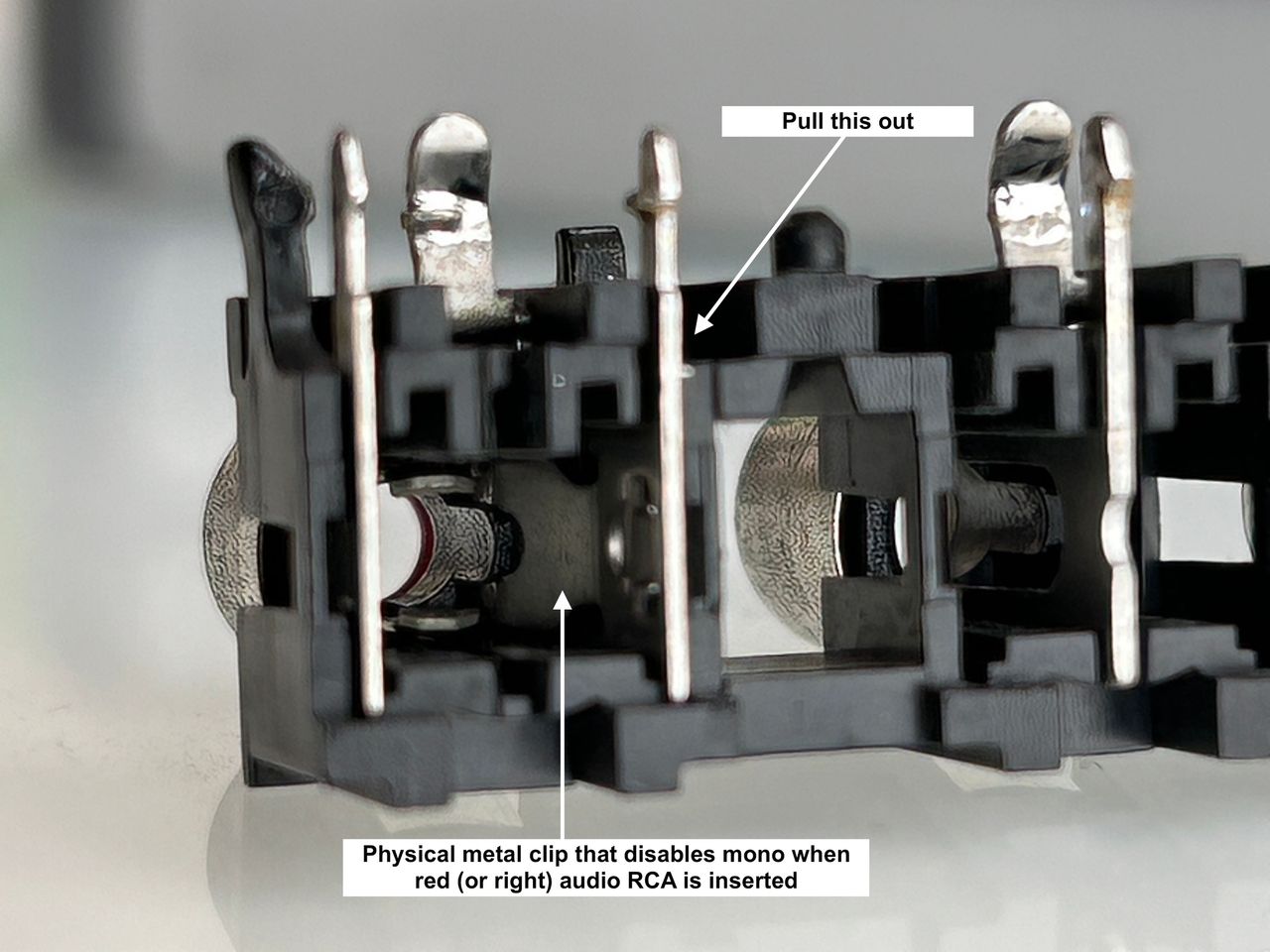
STEP 3: Permanently enable stereo
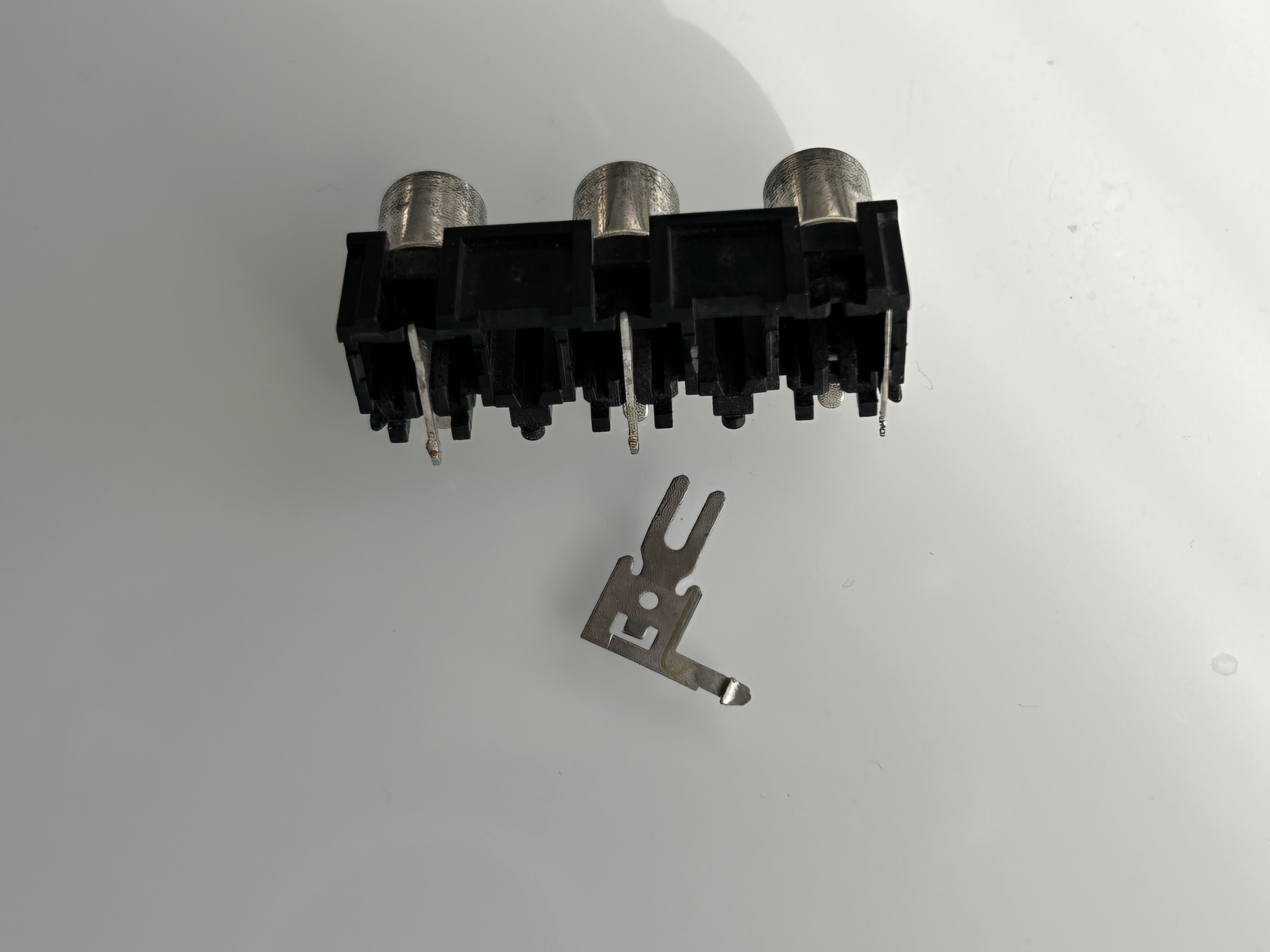
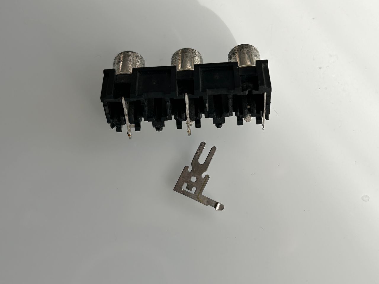
This is a relatively new step in the process. I desoldered the RCA connector at the back and removed the physical switch that activates mono audio when the red RCA port is unplugged. An alternative is to cut the trace to isolate the metal clip. However, I prefer the method below since I have a desoldering iron that makes this task much easier.
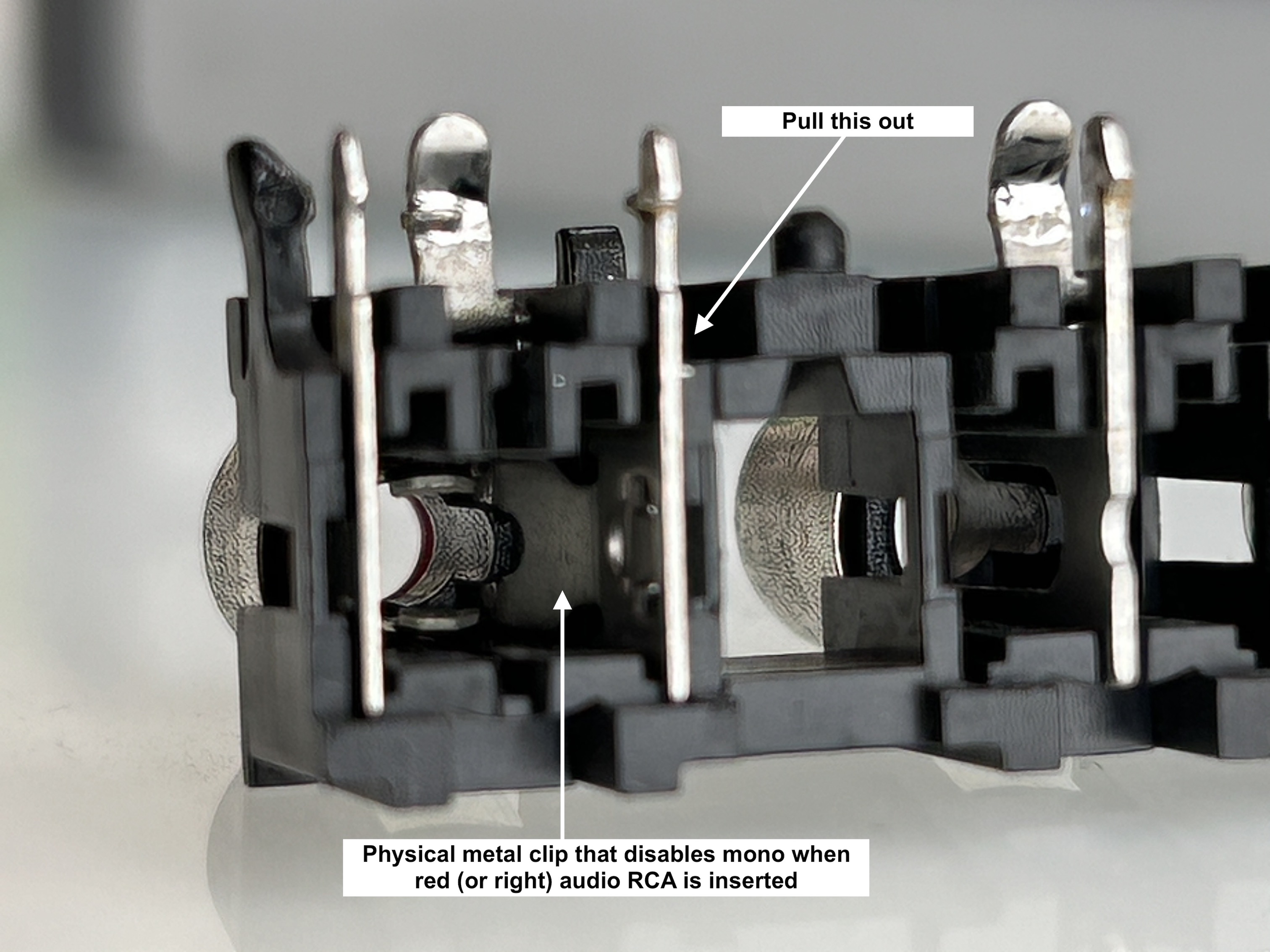
Clip that enables mono audio is pulled out.
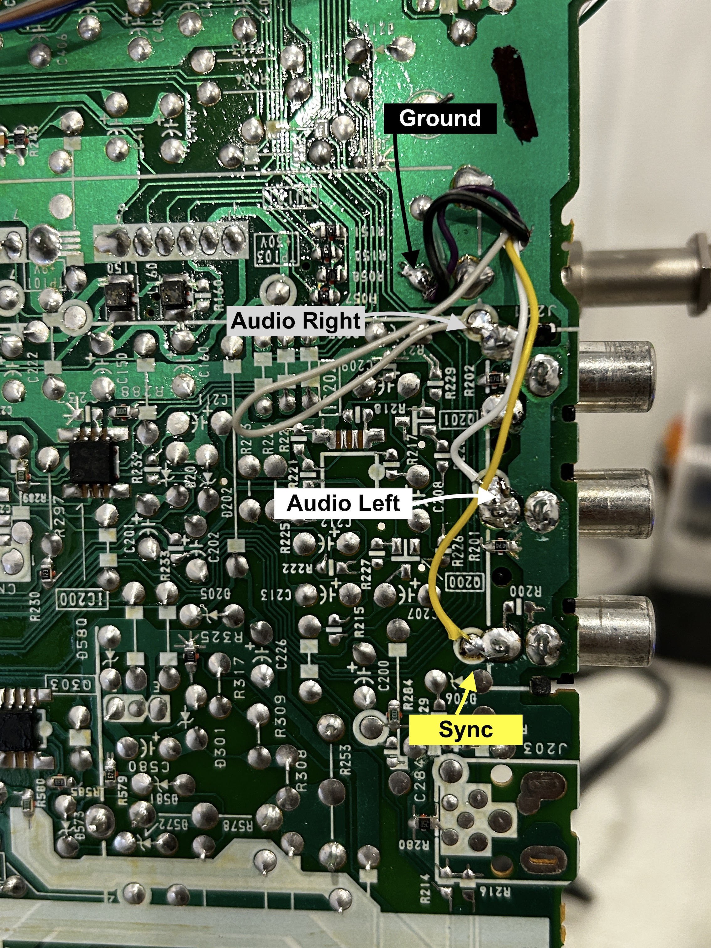
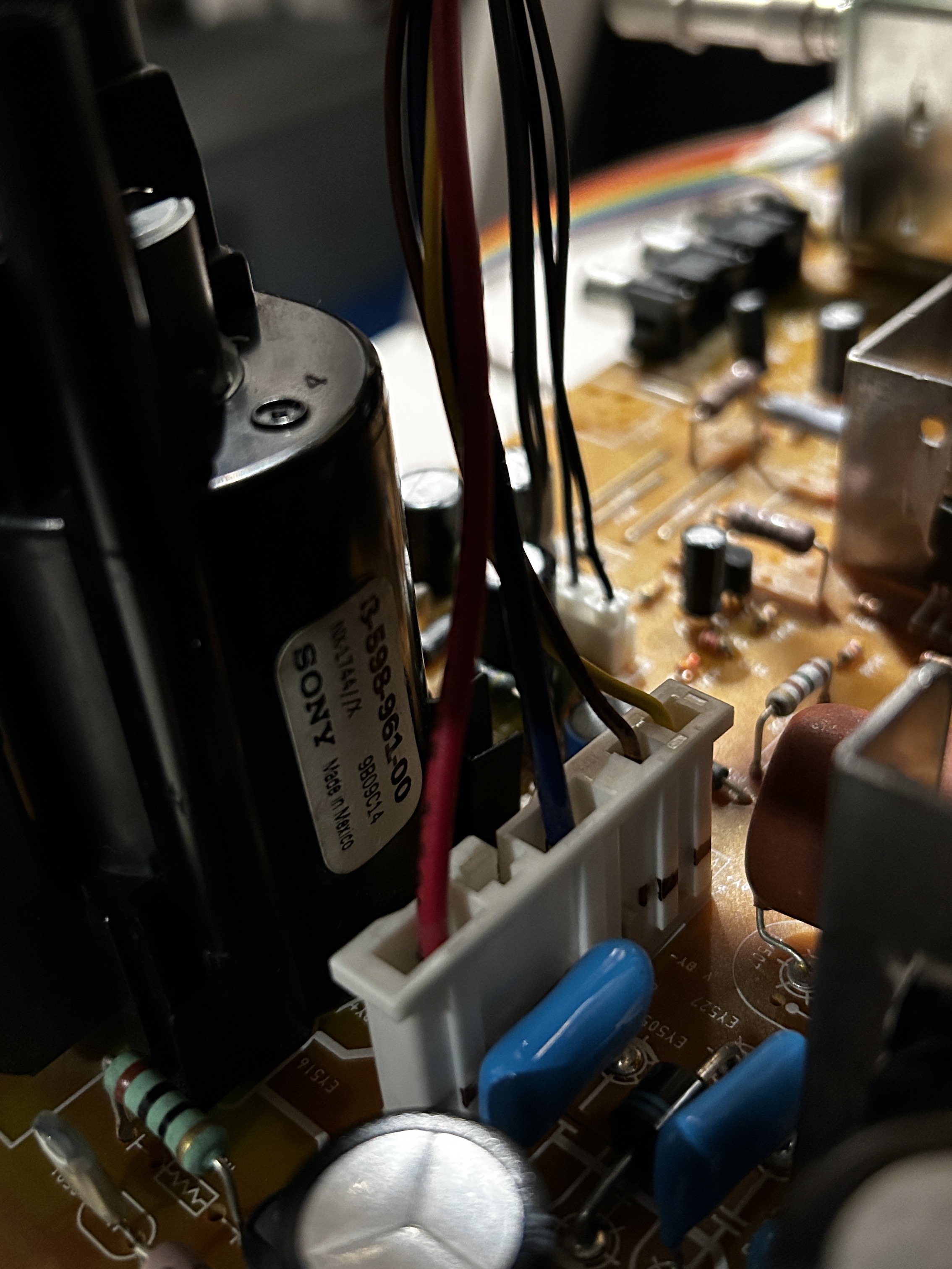
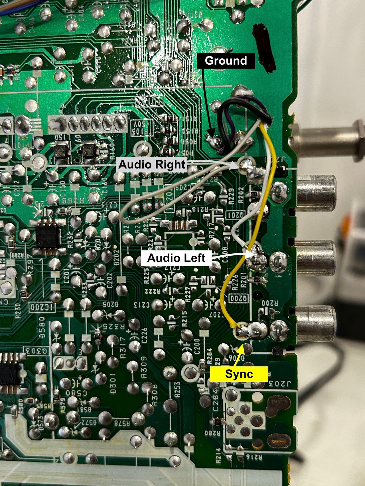
STEP 4: Connect Sync, Audio and Ground
Wire colors
- Black wires is common ground
- Grey wire is for right audio
- White wire is for left audio
- Yellow wire is for sync
- Orange and purple wires are auxillary and can be tied away for future use.
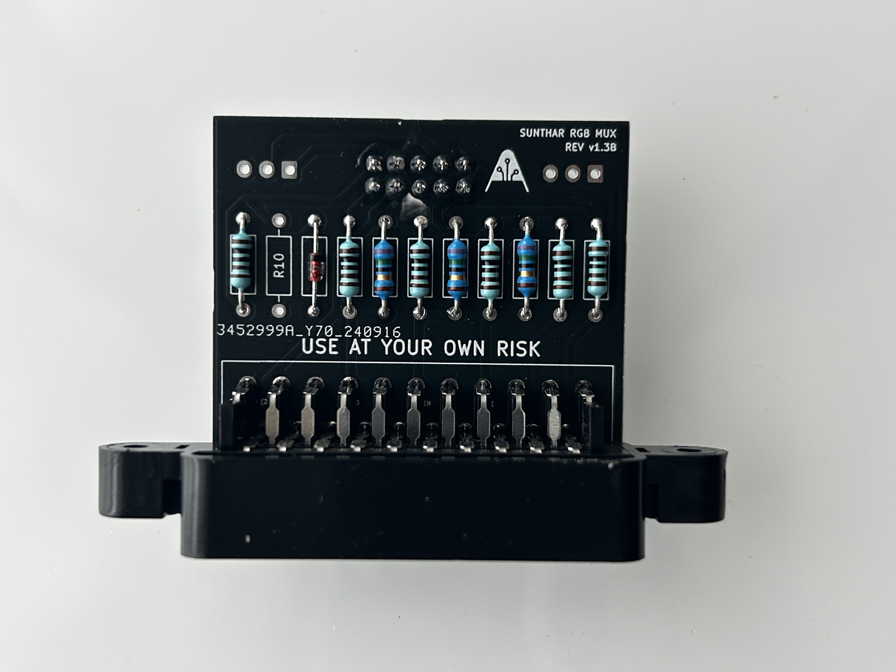
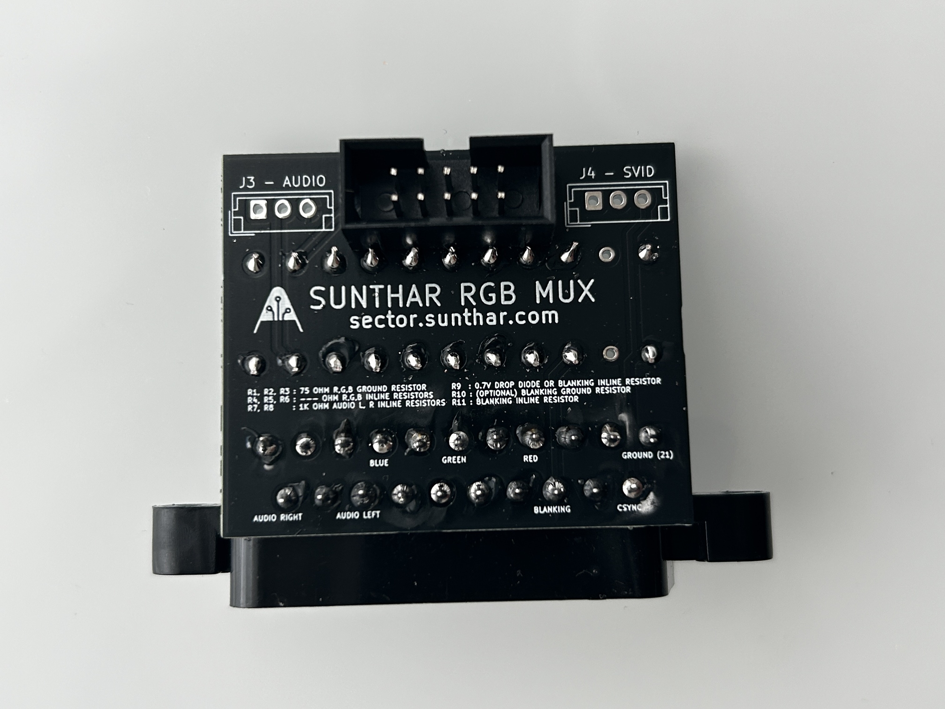
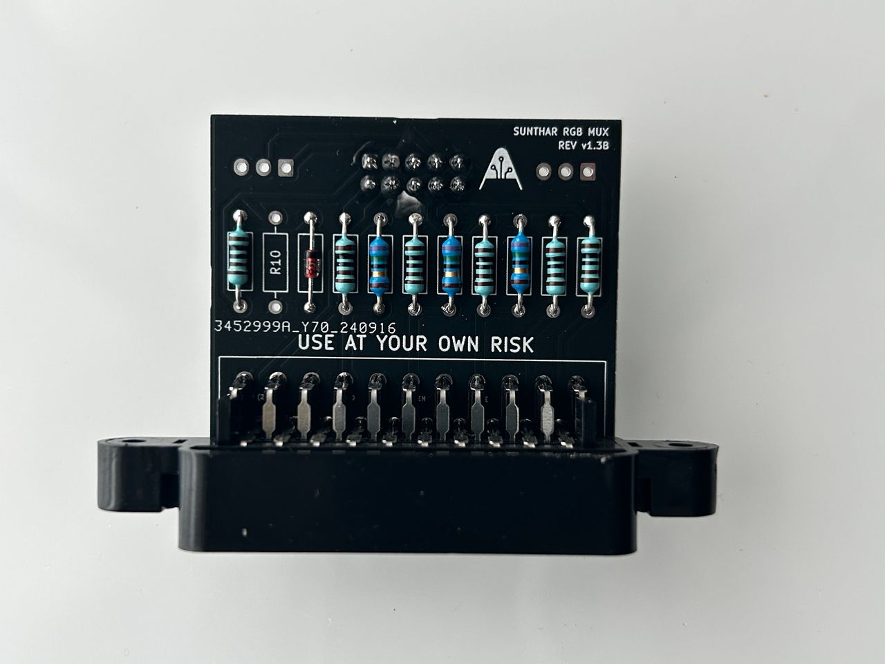
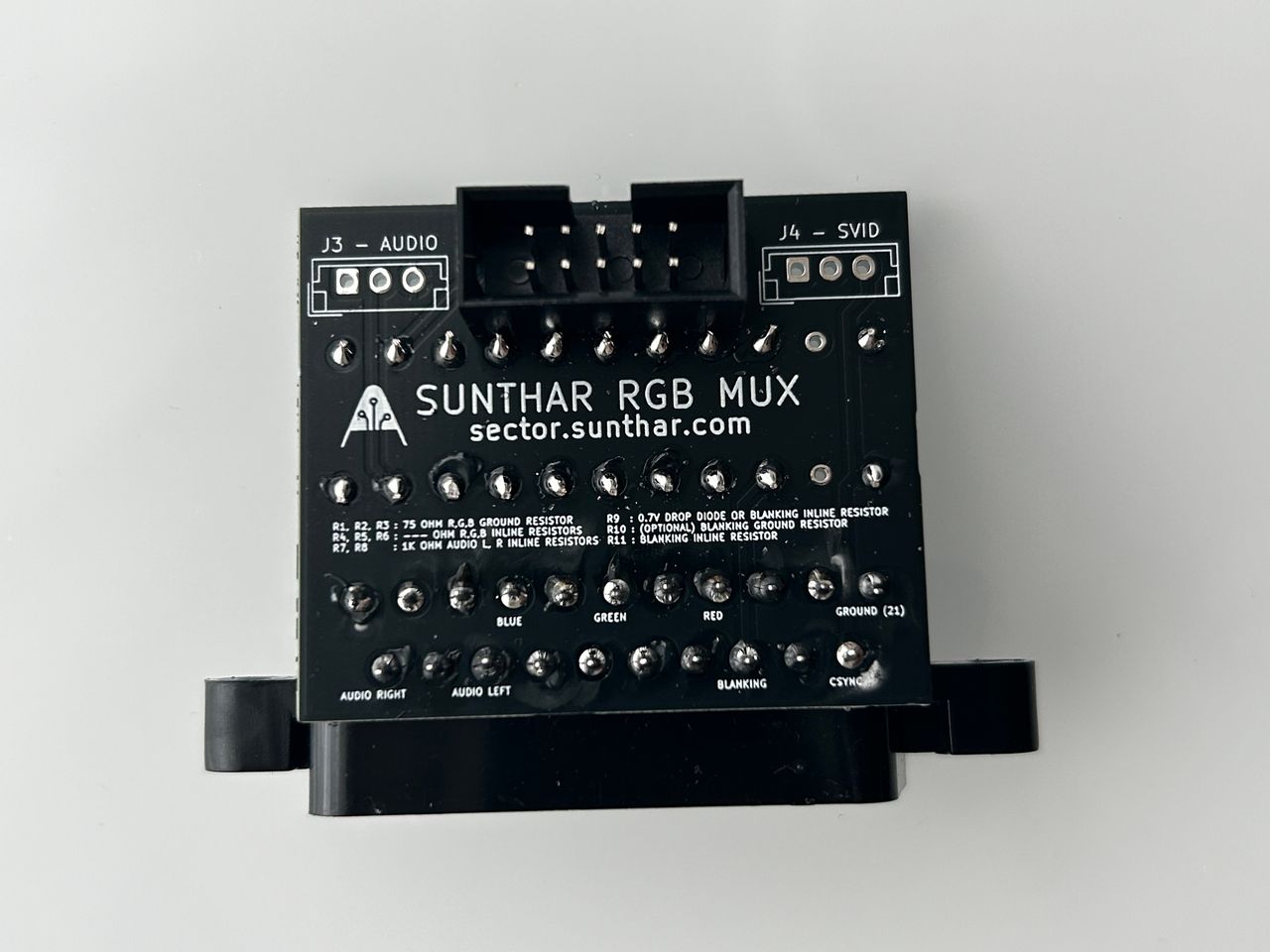
STEP 5: Build your mux board
This mod uses the RGB mux board. This is optional, but will make your mod easier and stable. You can also create the circuit presented in the schematics above without the board. Please also checkout the mux calculator to play with your own values.
| On Sony CRT Chassis | KV-20S42 |
|---|---|
| CRT RGB inline resistor | 5.6kΩ |
| CRT RGB ground resistors removed | 680Ω |
| 0.1μF caps replaced | No |
| Add diodes on chassis RGB lines? | Yes |
| Add blanking diode on chassis | No |
| RGB mux board | KV-20S42 |
|---|---|
| Mux board RGB termination (R1, R2, R3) | 75Ω |
| Mux board RGB inline resistors (R4, R5, R6) | 1kΩ |
| Mux board Audio LR (R7, R8) | 1kΩ |
| Mux board blanking diode (R9) | 1N4148 |
| Mux board blanking ground resistor (R10) | open |
| Mux board blanking resistor (R11) | 1kΩ |
Compatible mux boards:
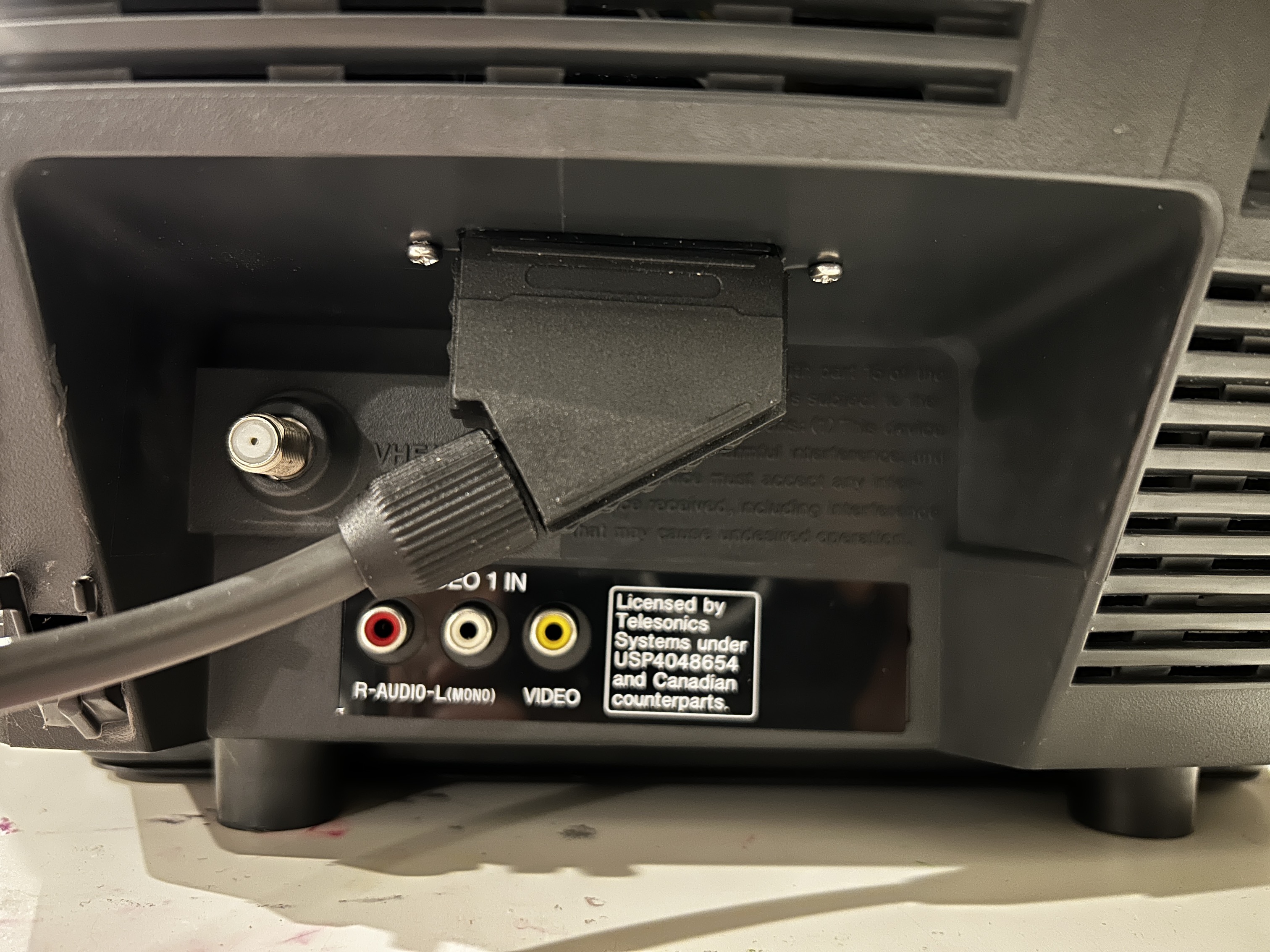
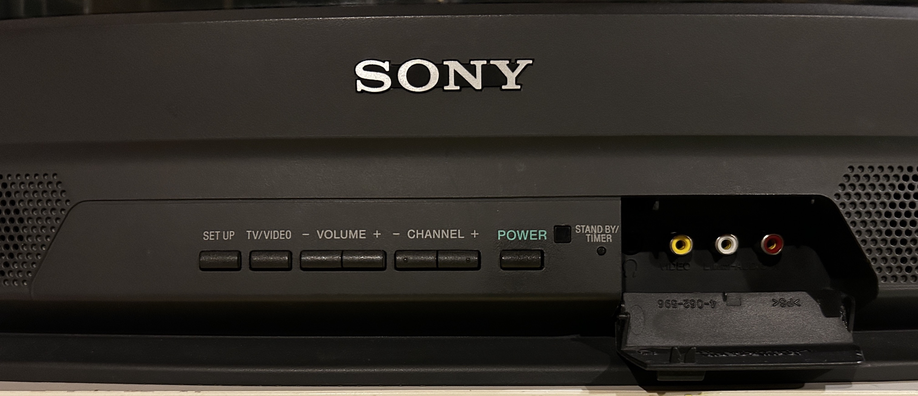
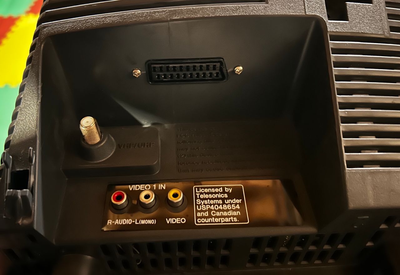
STEP 6: Attach the female SCART connector to TV
Creating a SCART cutout and mounting it is an art. I have a dedicated section for it. How to create and mount a SCART female plug?
Depending on your CRT, you might need to find a good place to mount the SCART port.

Getting into the service menu
- Turn the set on and then put into standby
- Press the
Display,5,VOL +buttons in sequence - Turn on the CRT and you should be in service mode
- Use buttons "1" and "4" on the remote control to navigate the service menu
- Use buttons "3" and "6" to adjust the selected data
Pictures of the mod
OSD mux mod

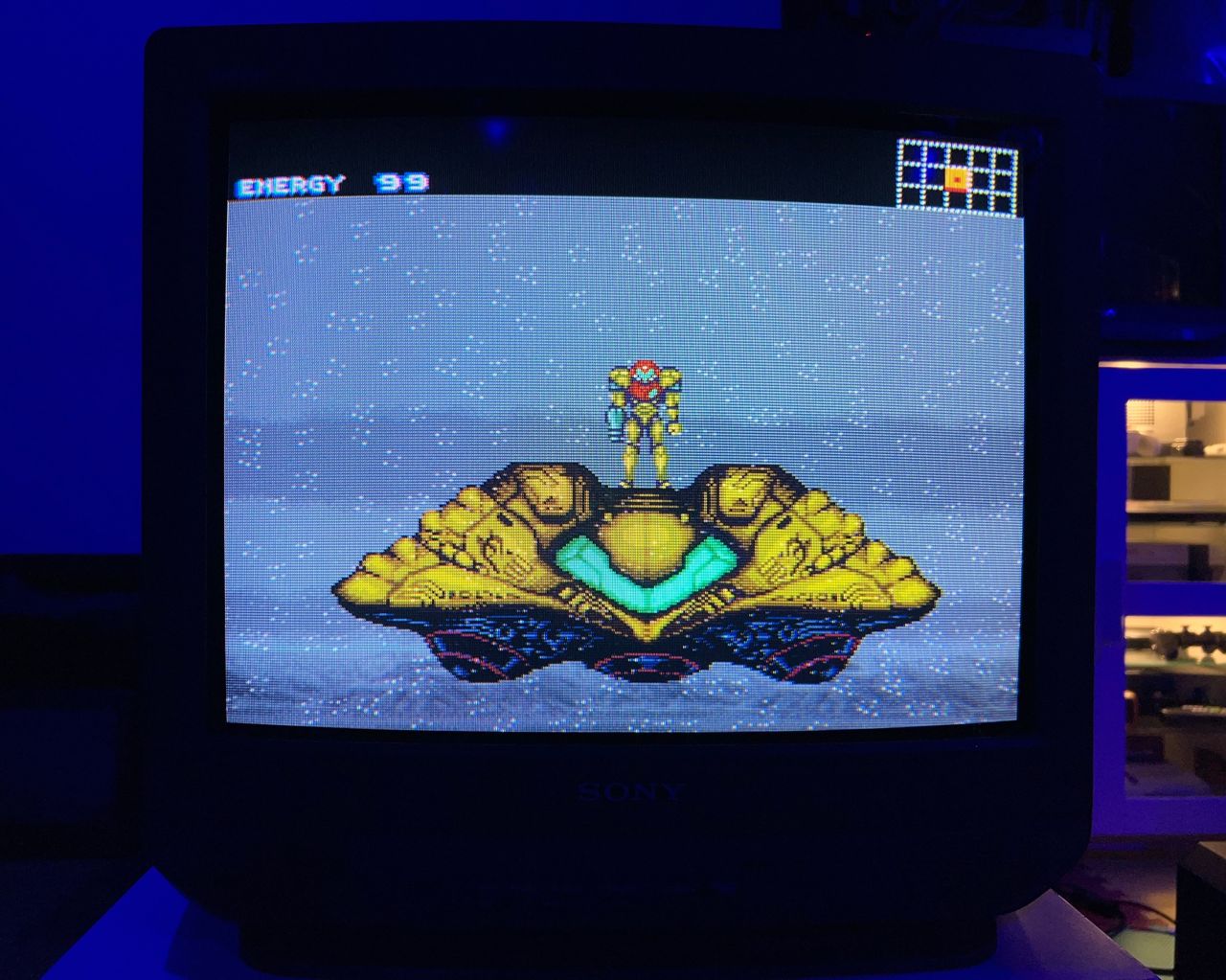
Games
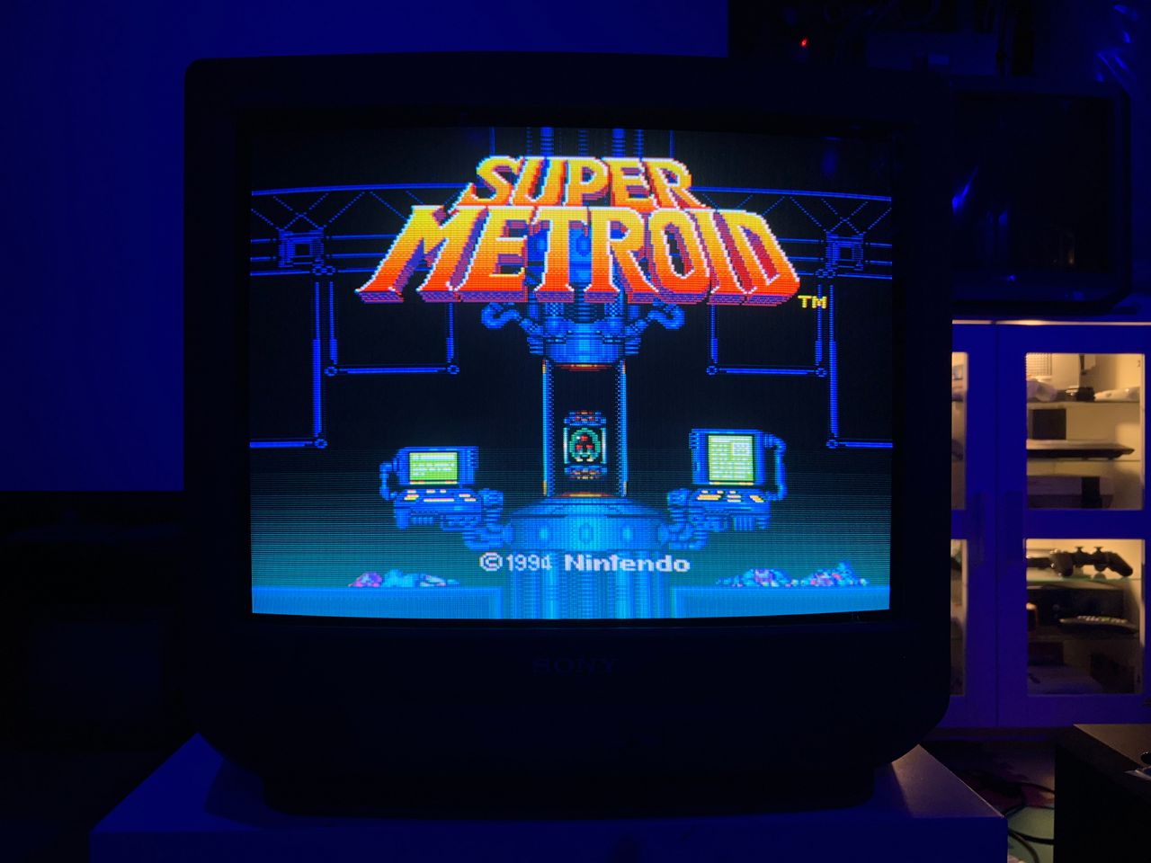
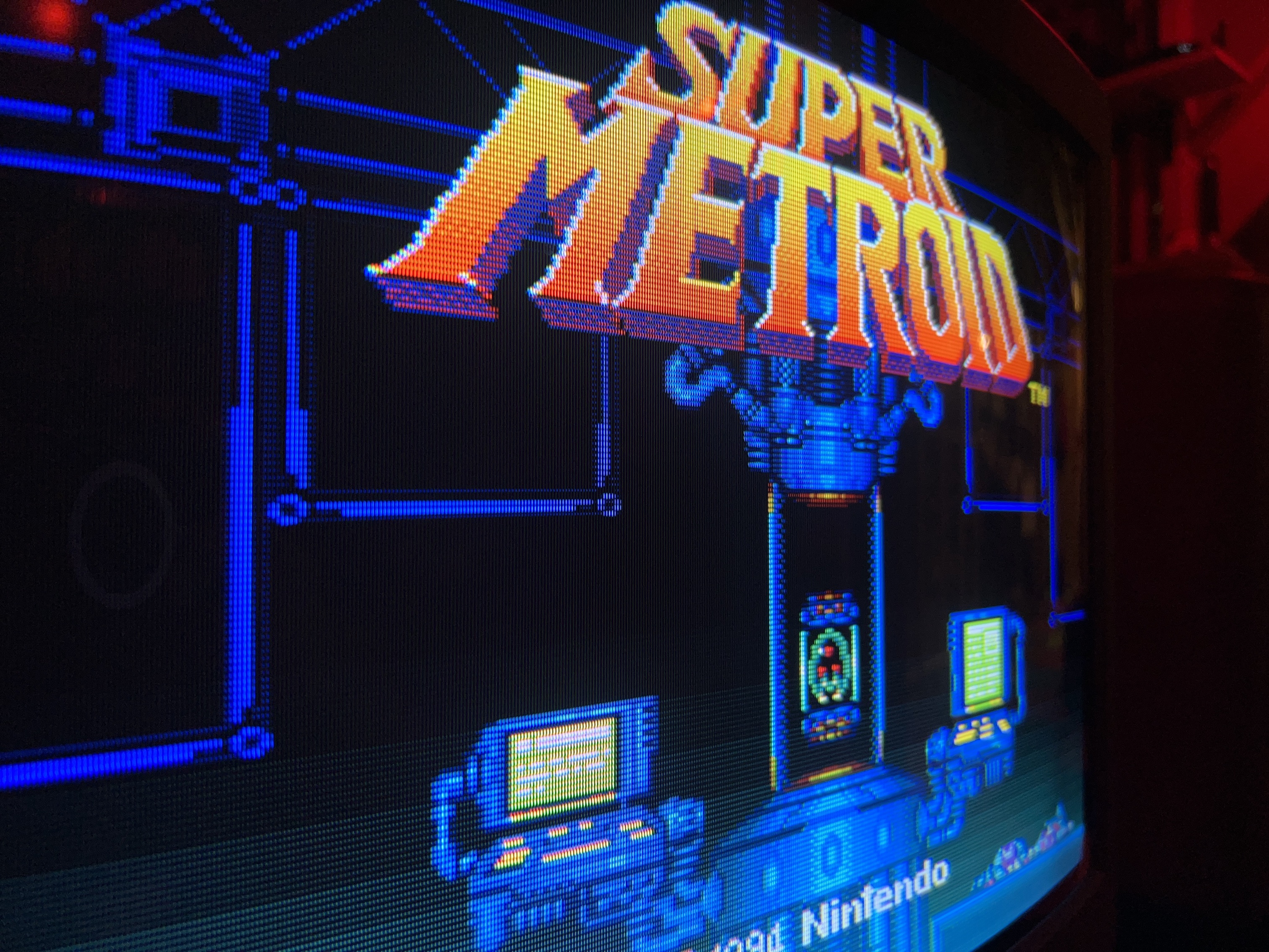
SNES - Metroid 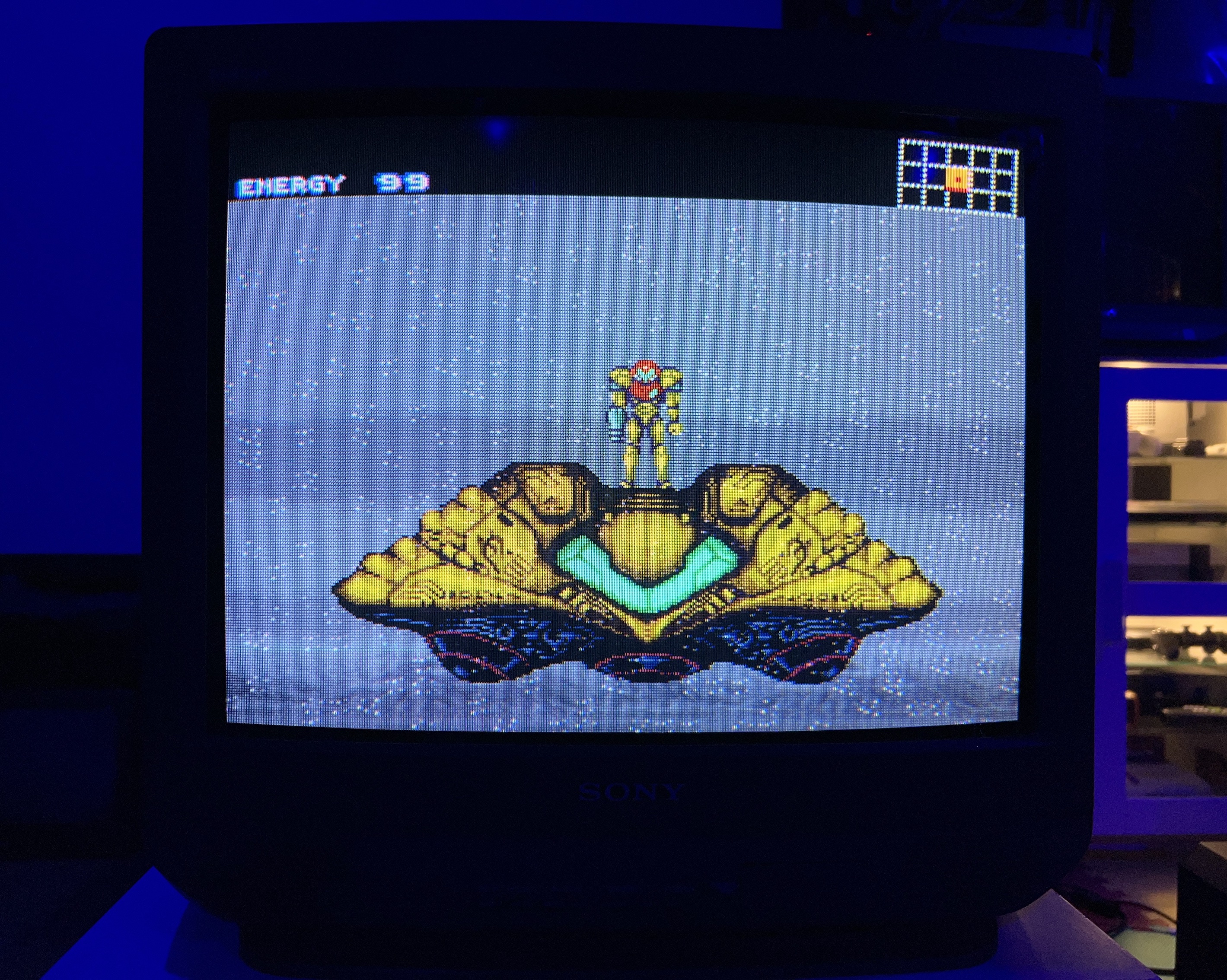
SNES - Super Mario World 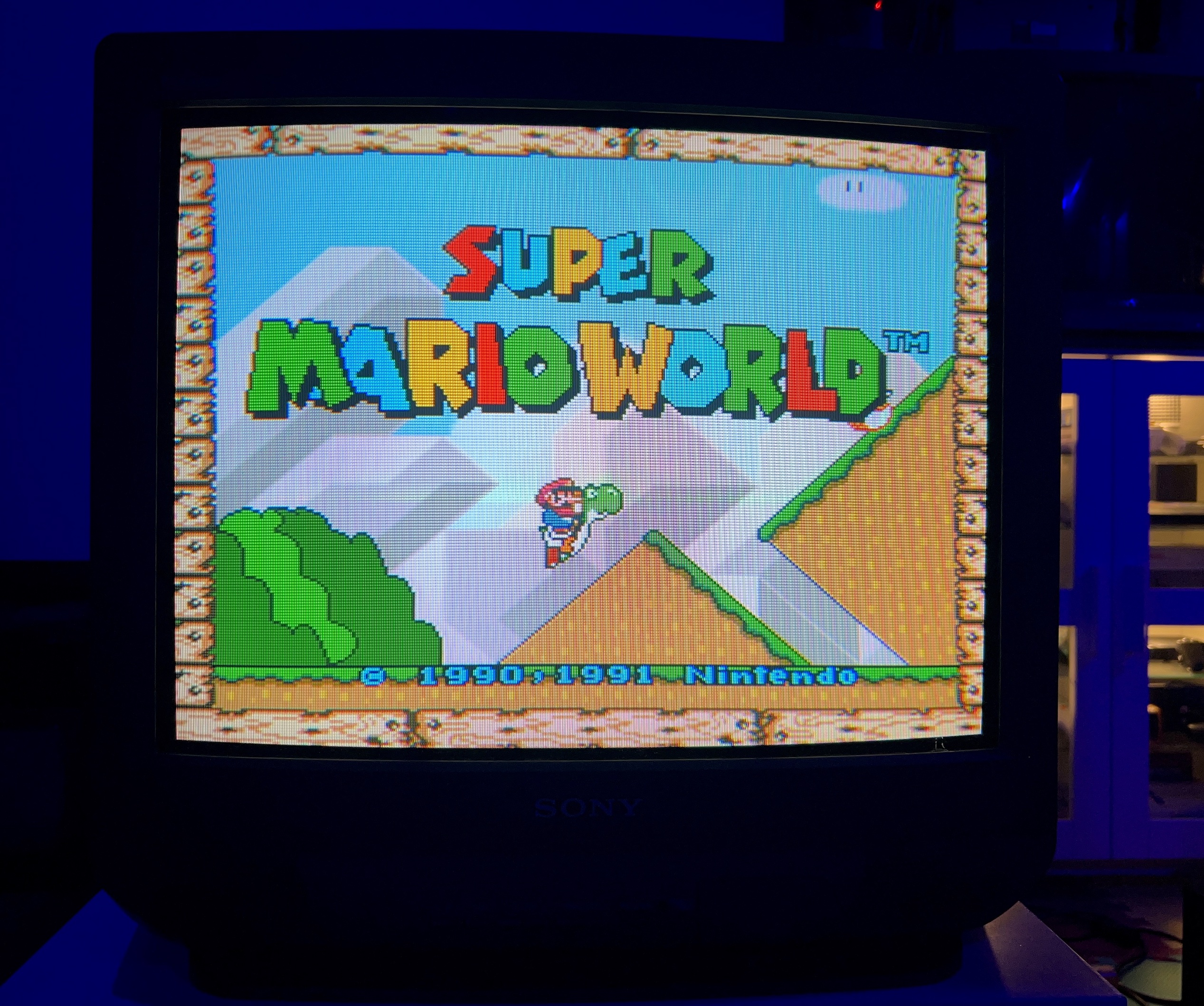
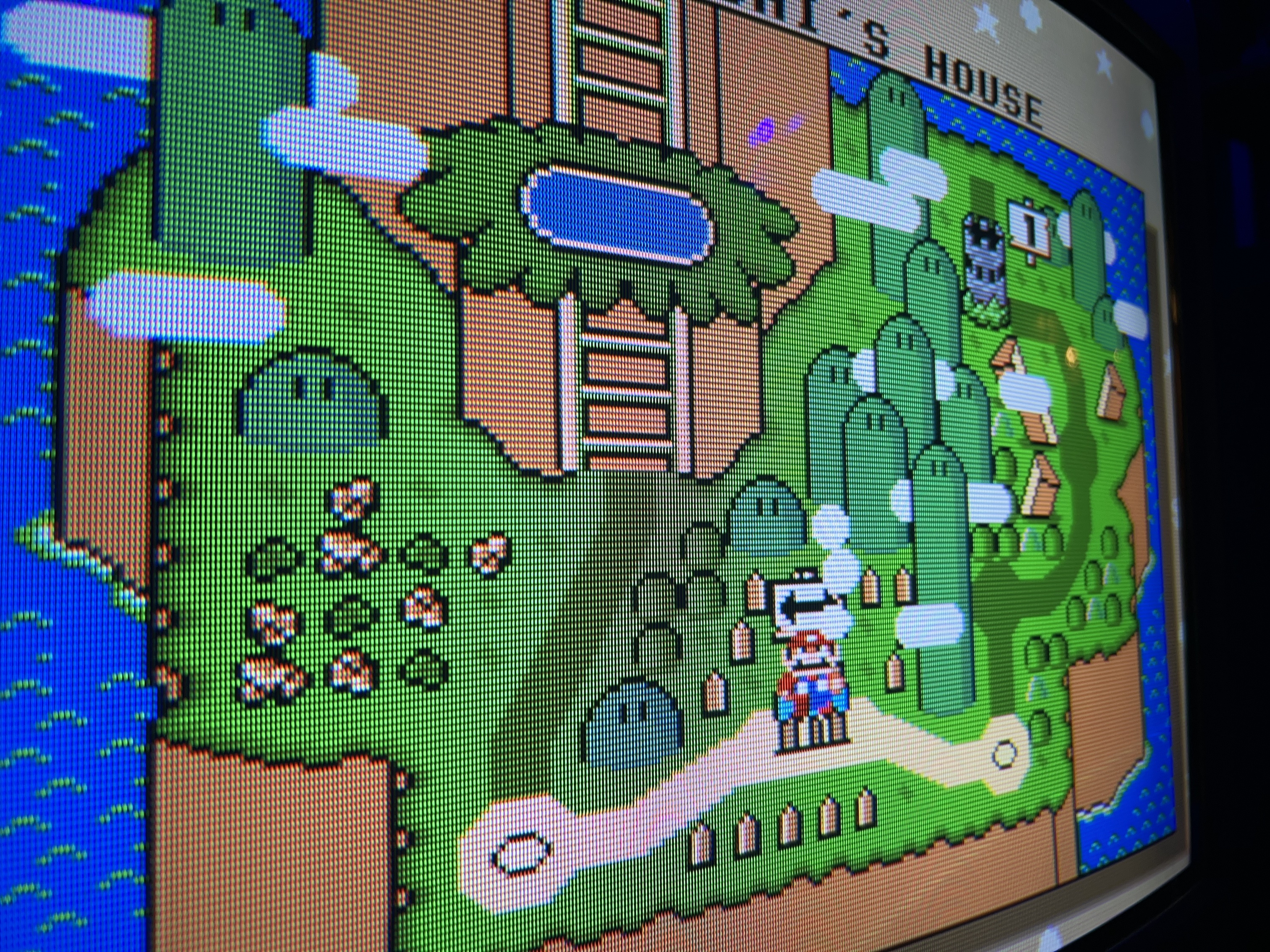
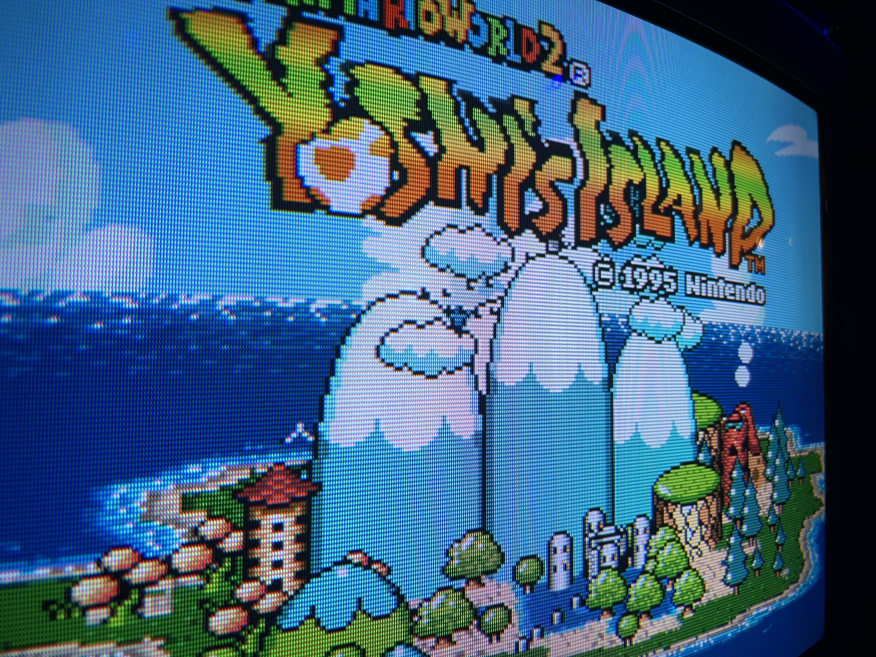
SNES - Yoshi's Island 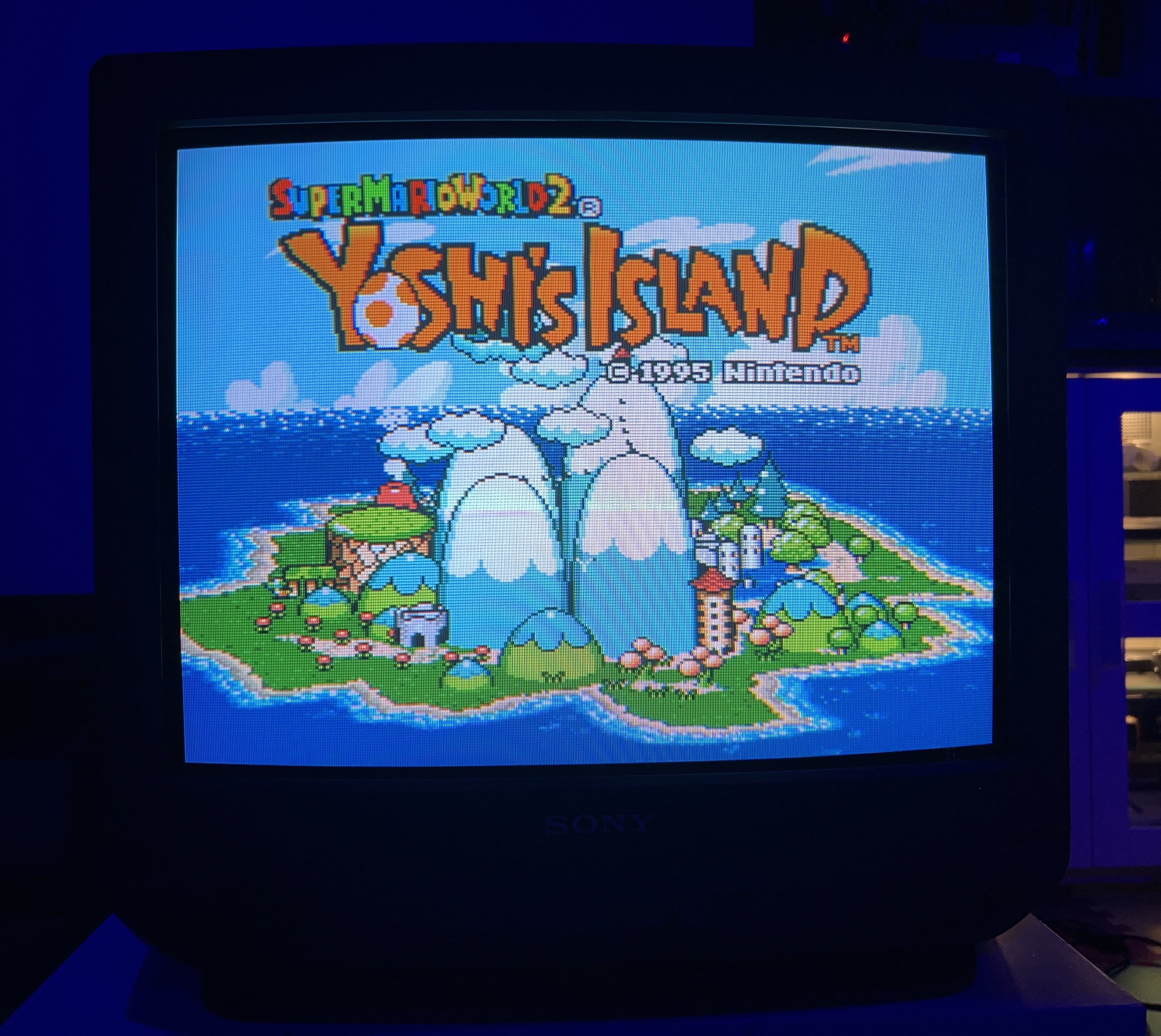
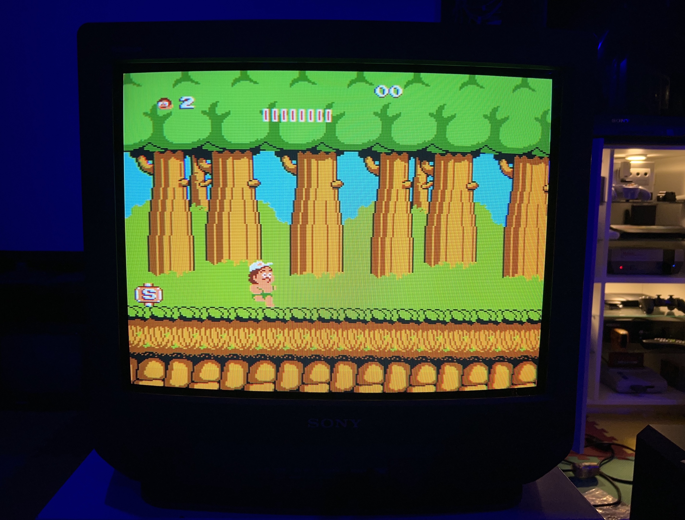
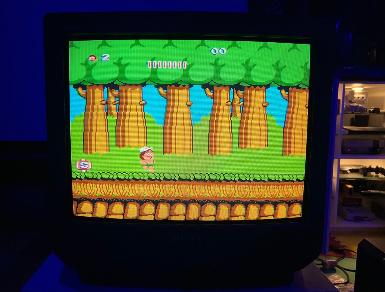
NES - Adventure Island 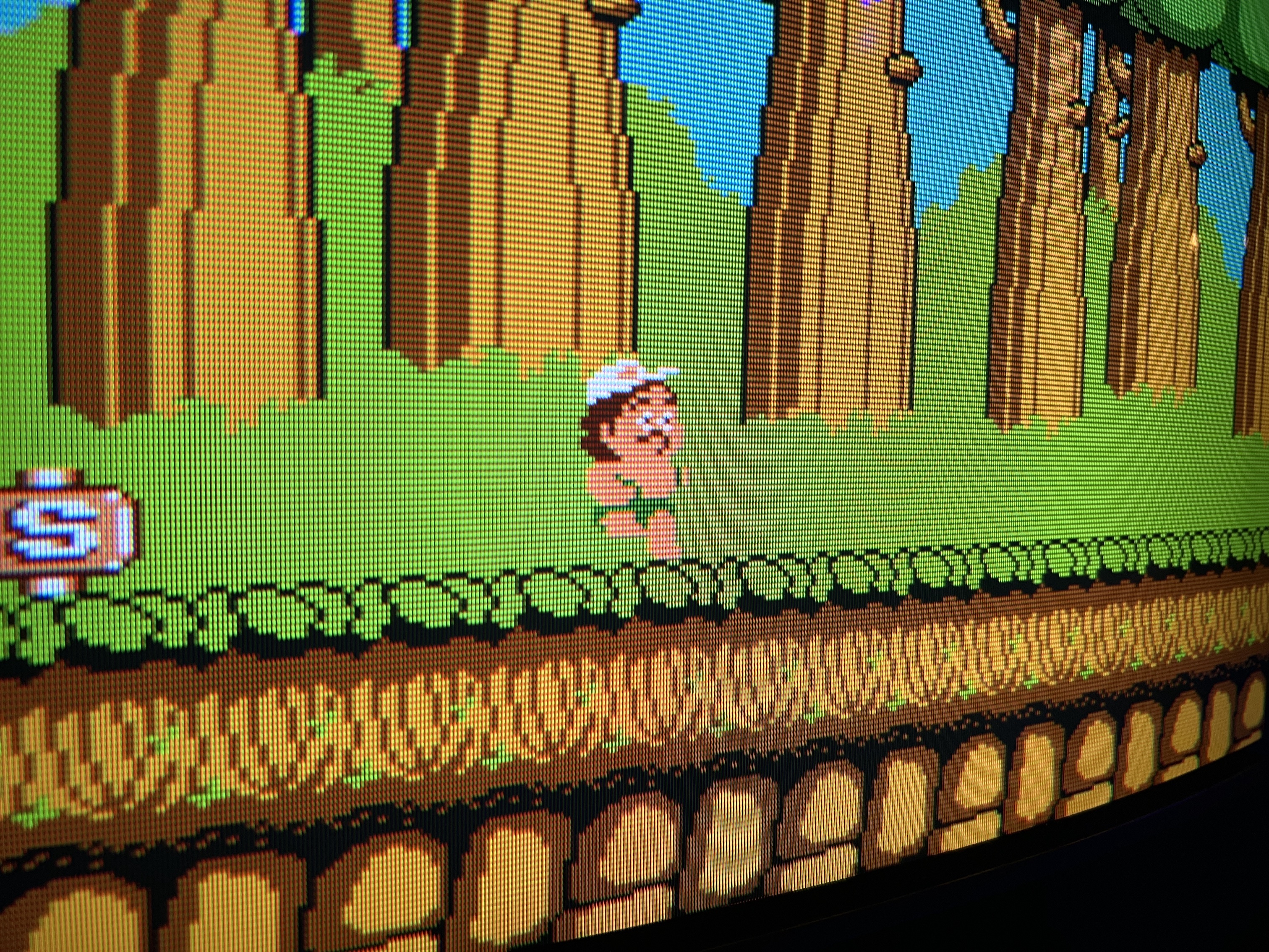
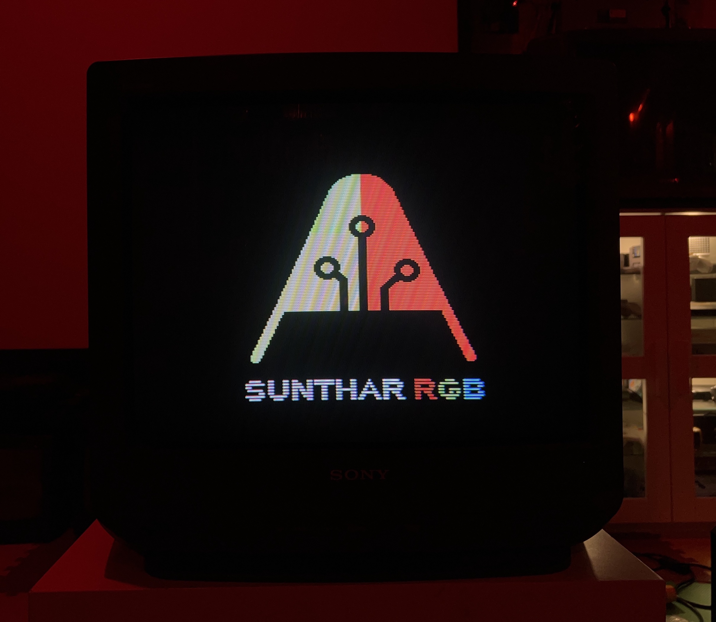
PS1 - Boot 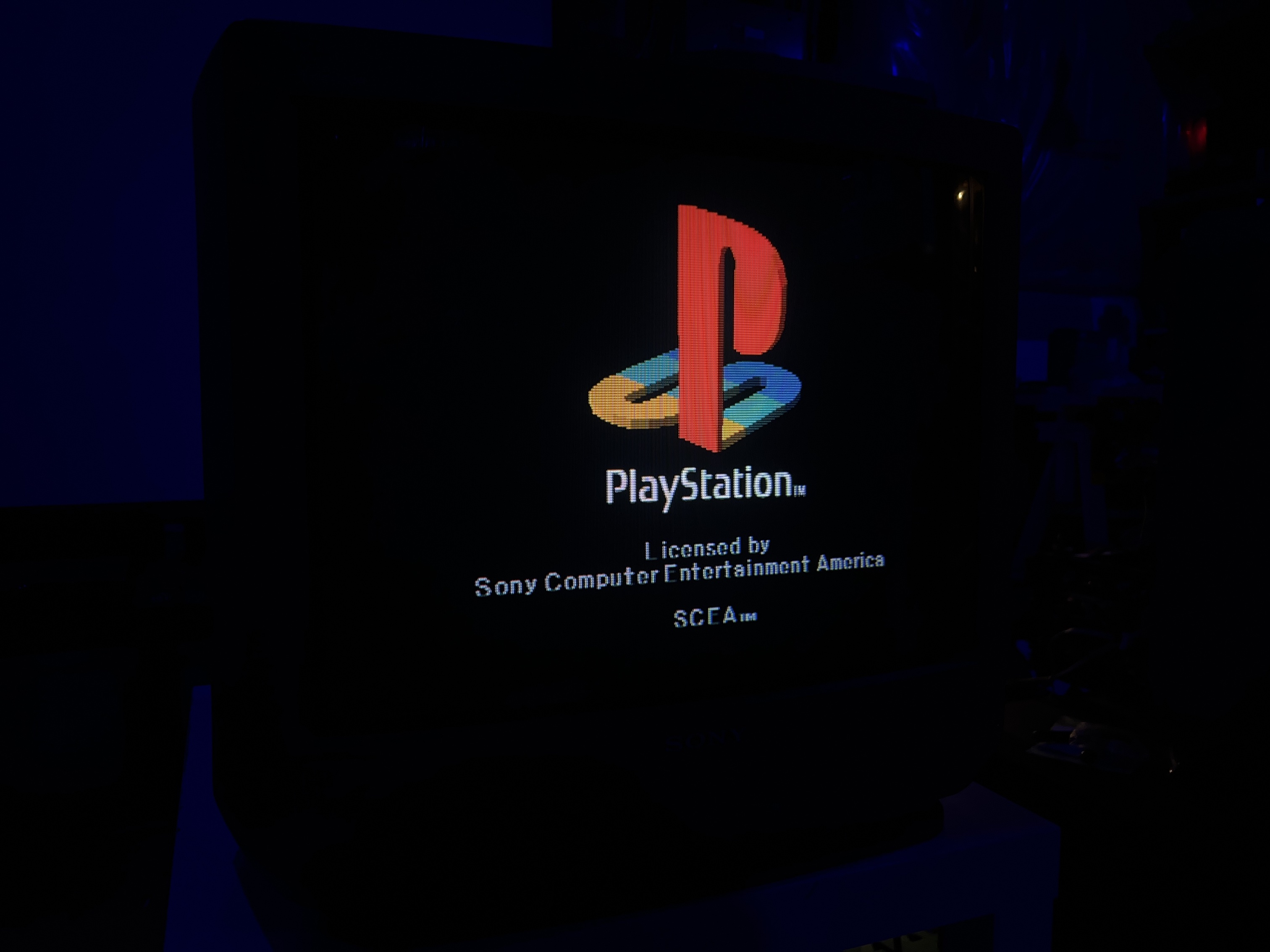
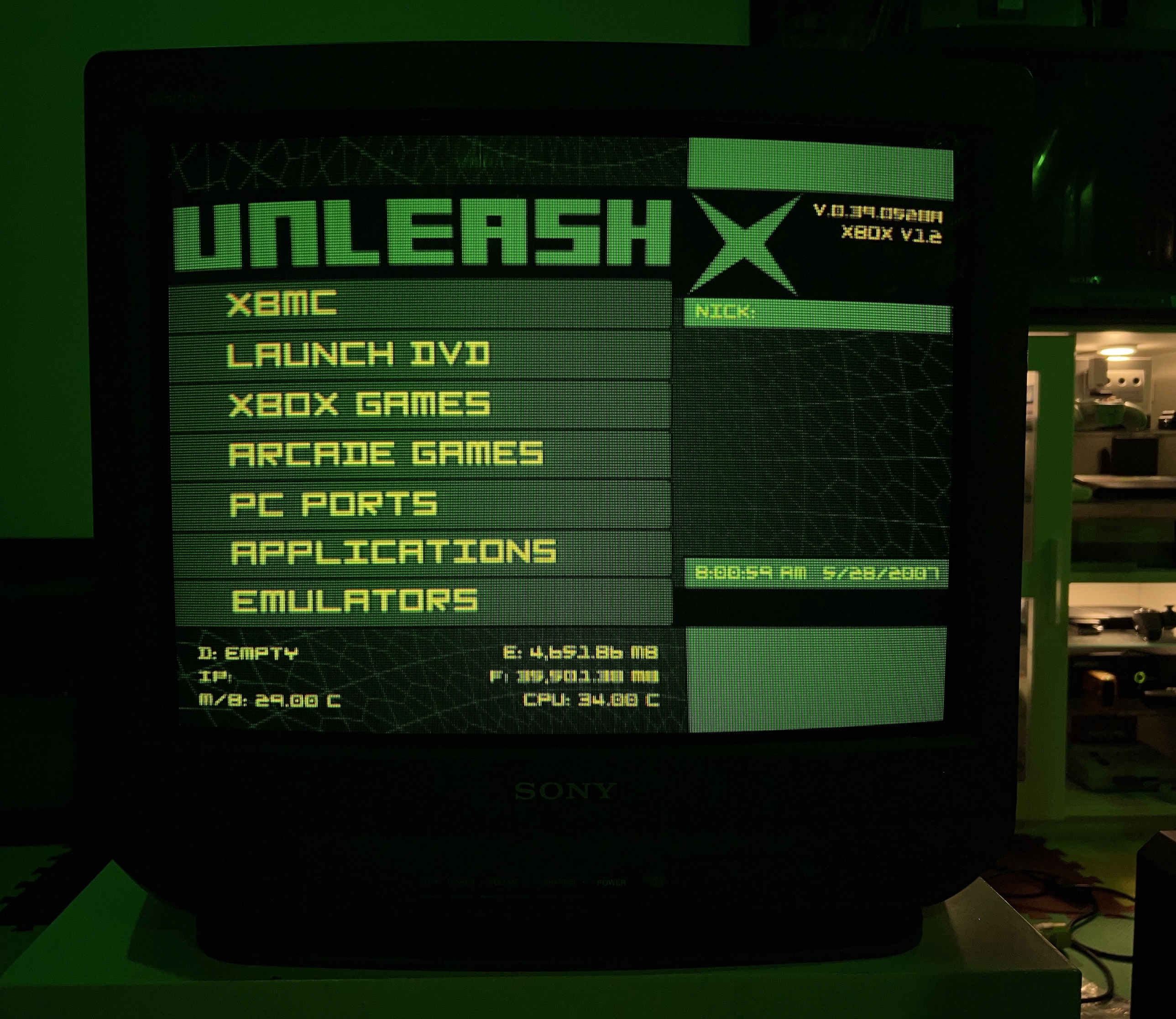
XBOX 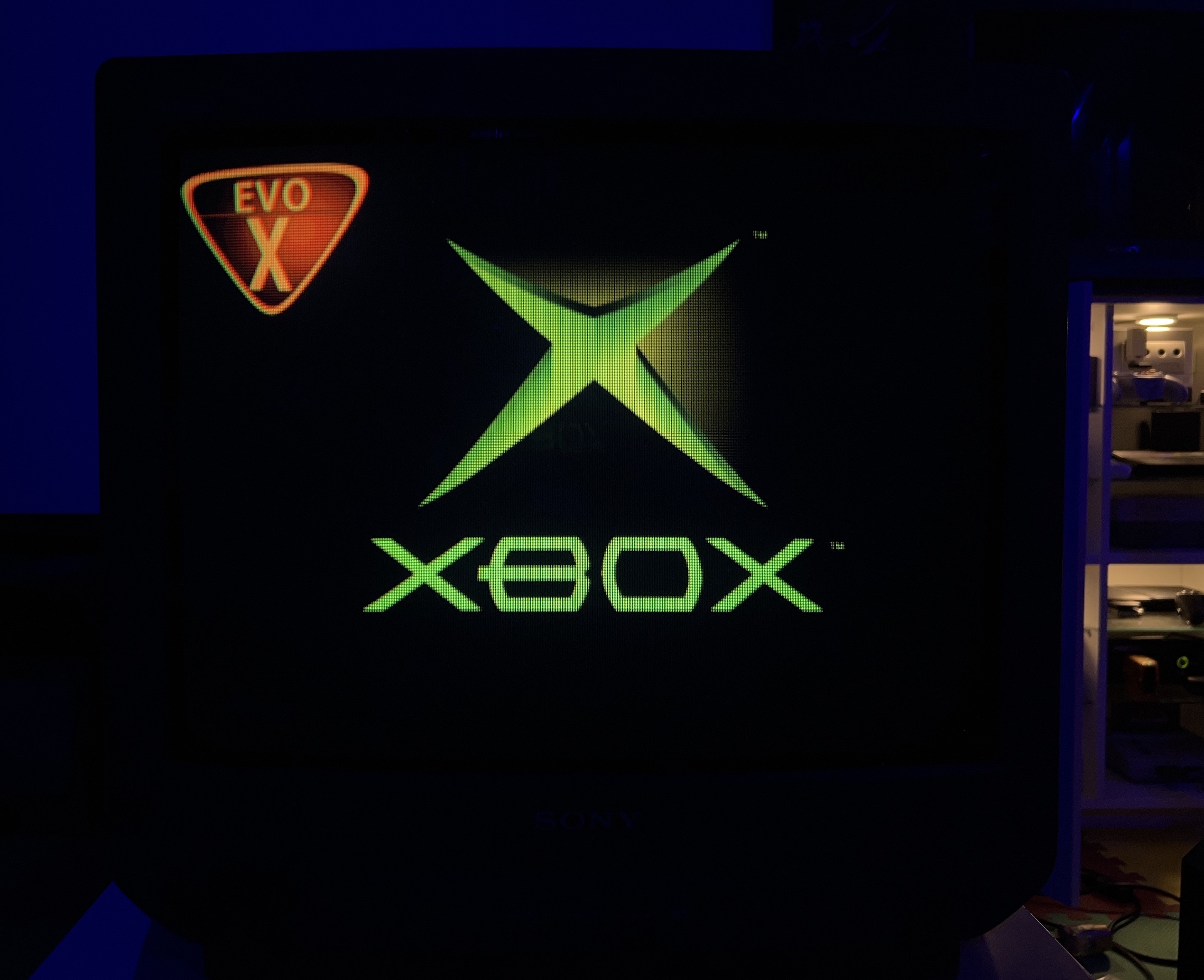
From different 20S42 set
OSD overlay 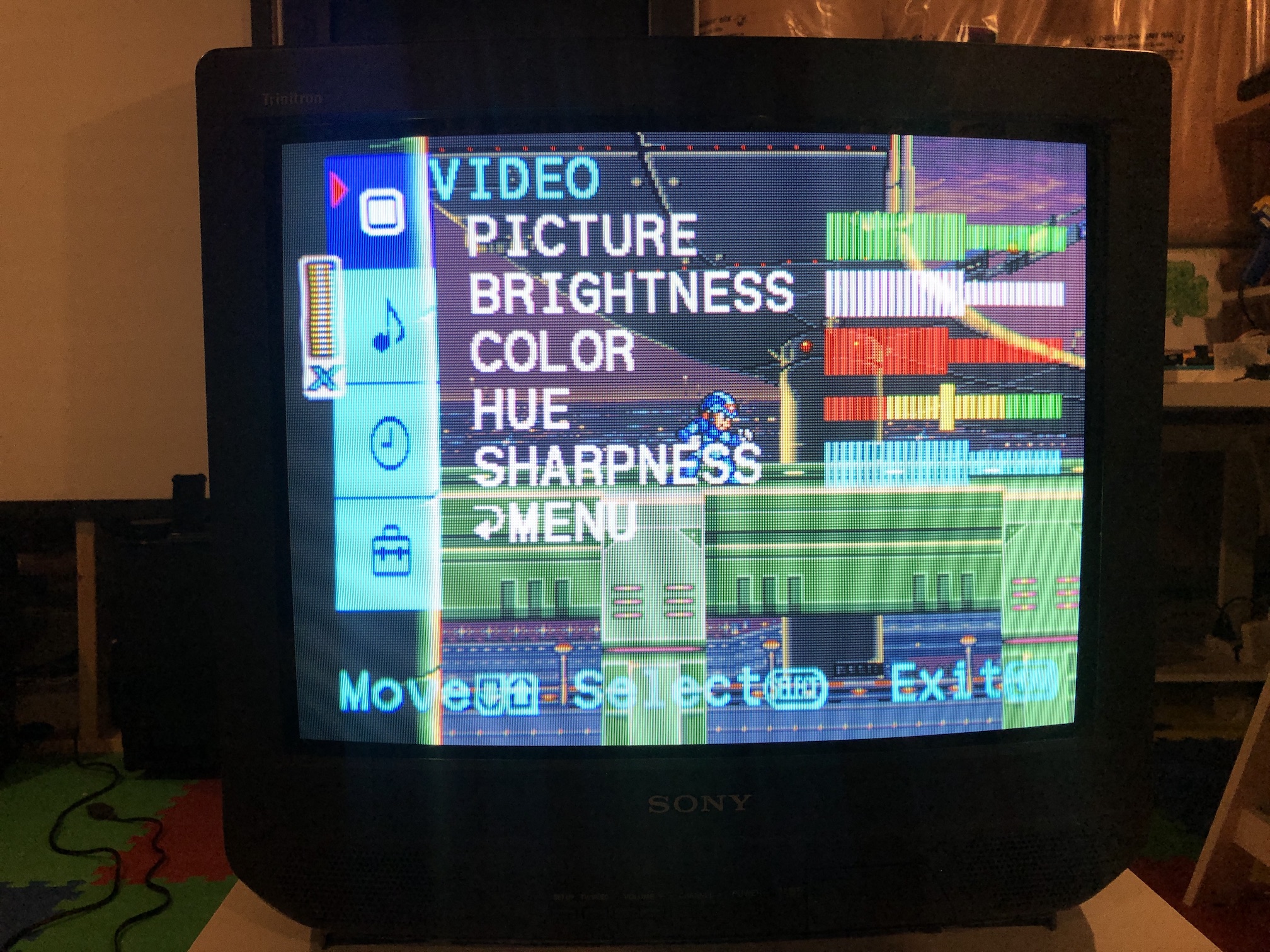
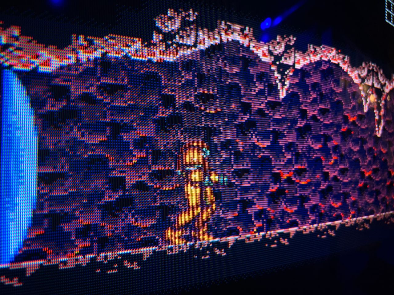
SNES - Metroid 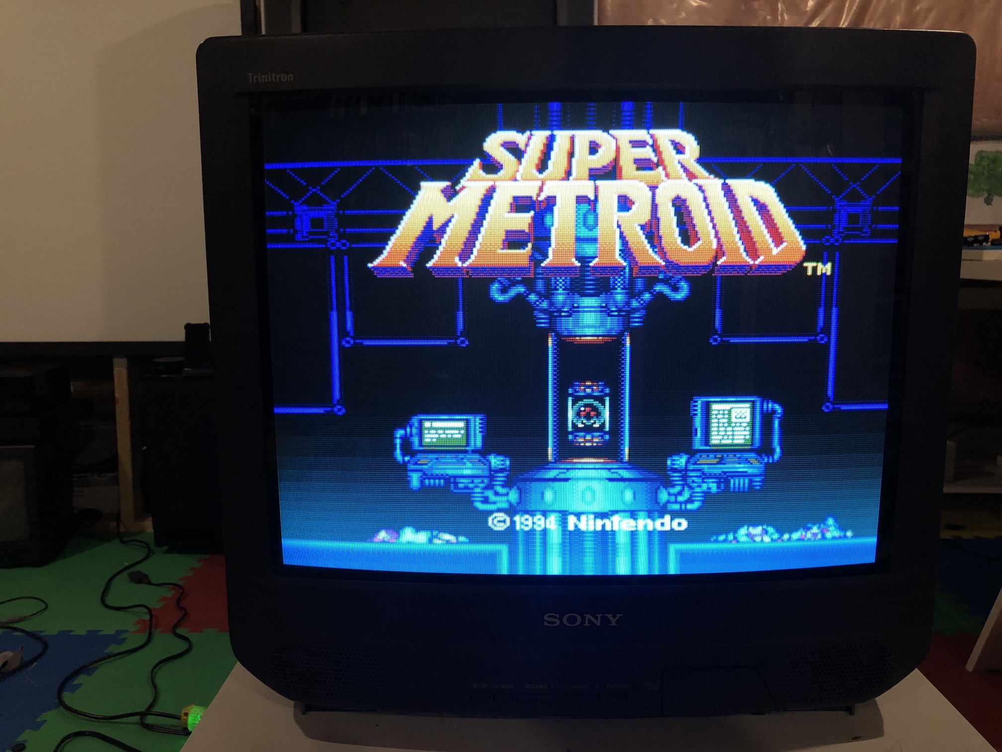
SNES - Super Mario World 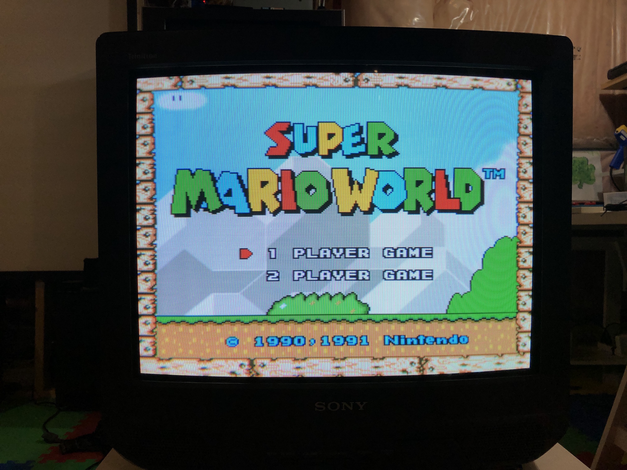
SNES - Contra 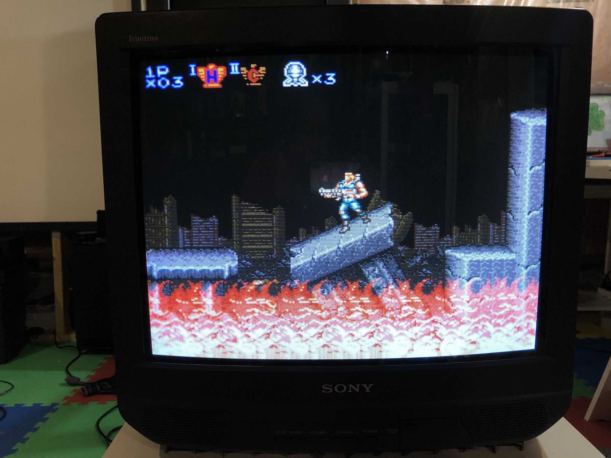
NES - Adventure Island 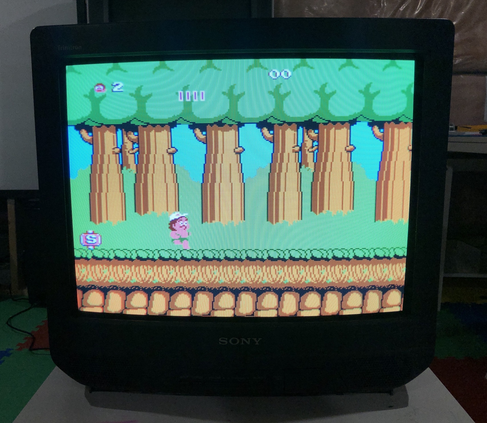
NES - Adventure Island closeup 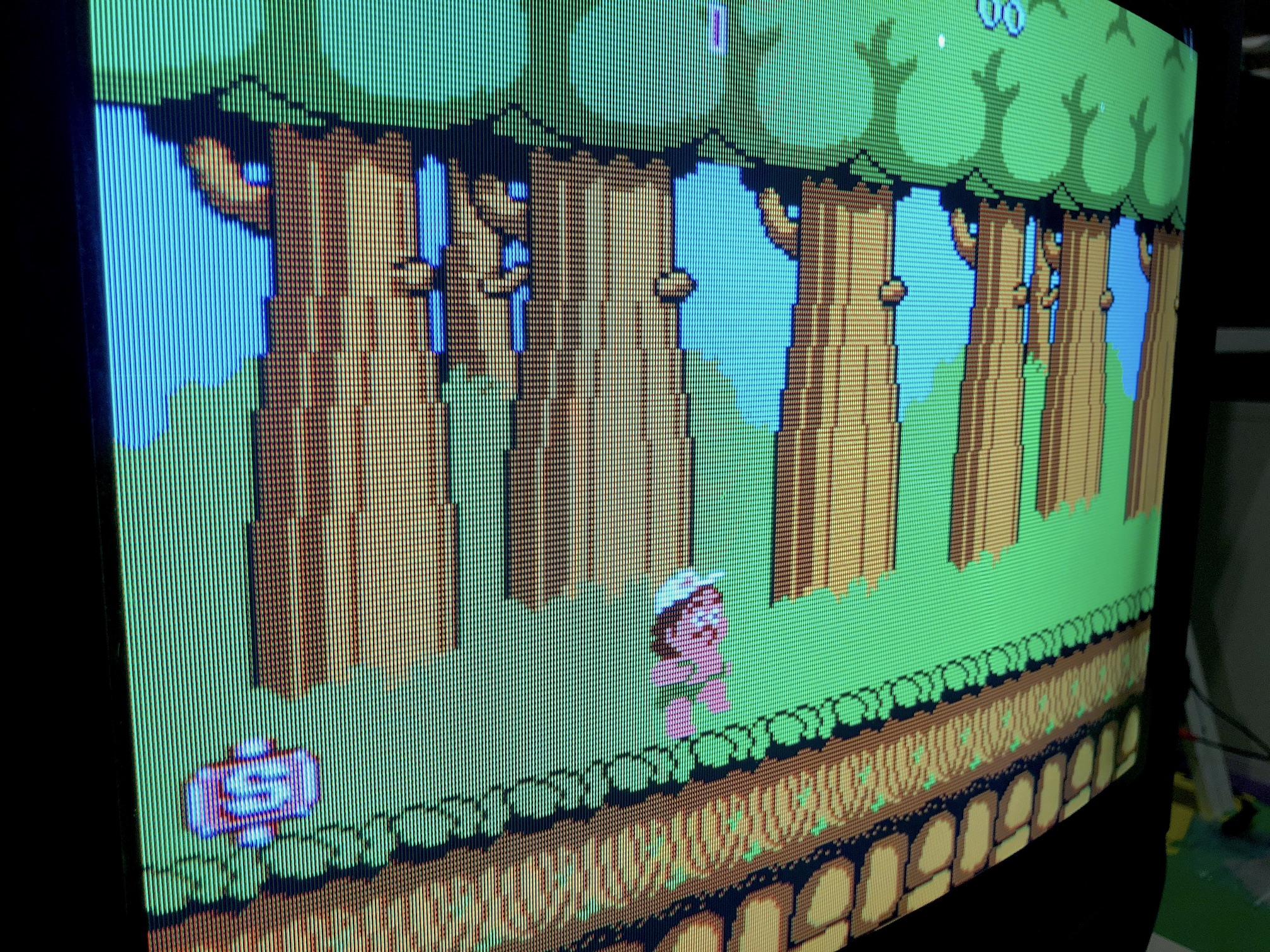
PS1 - Boot 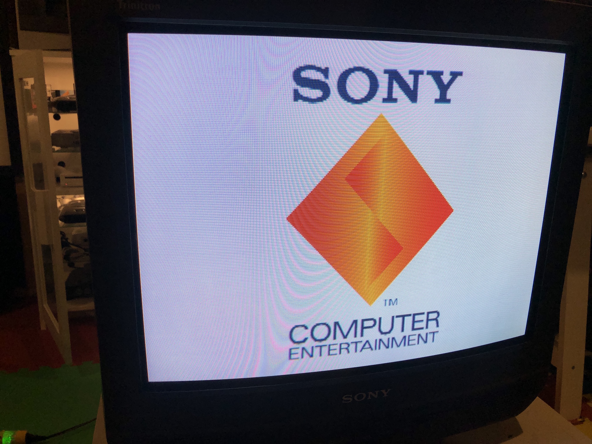
SNES Megaman X closeup 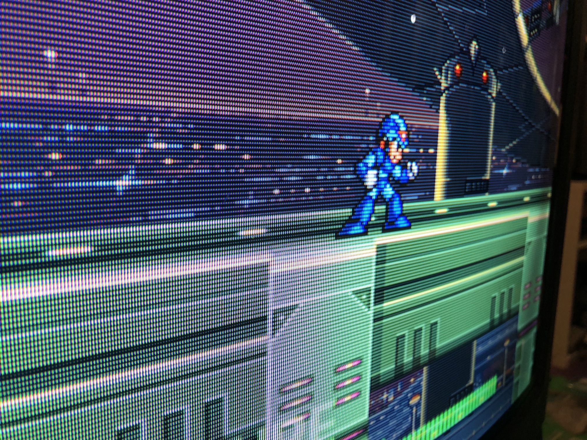
Contra 3 closeup 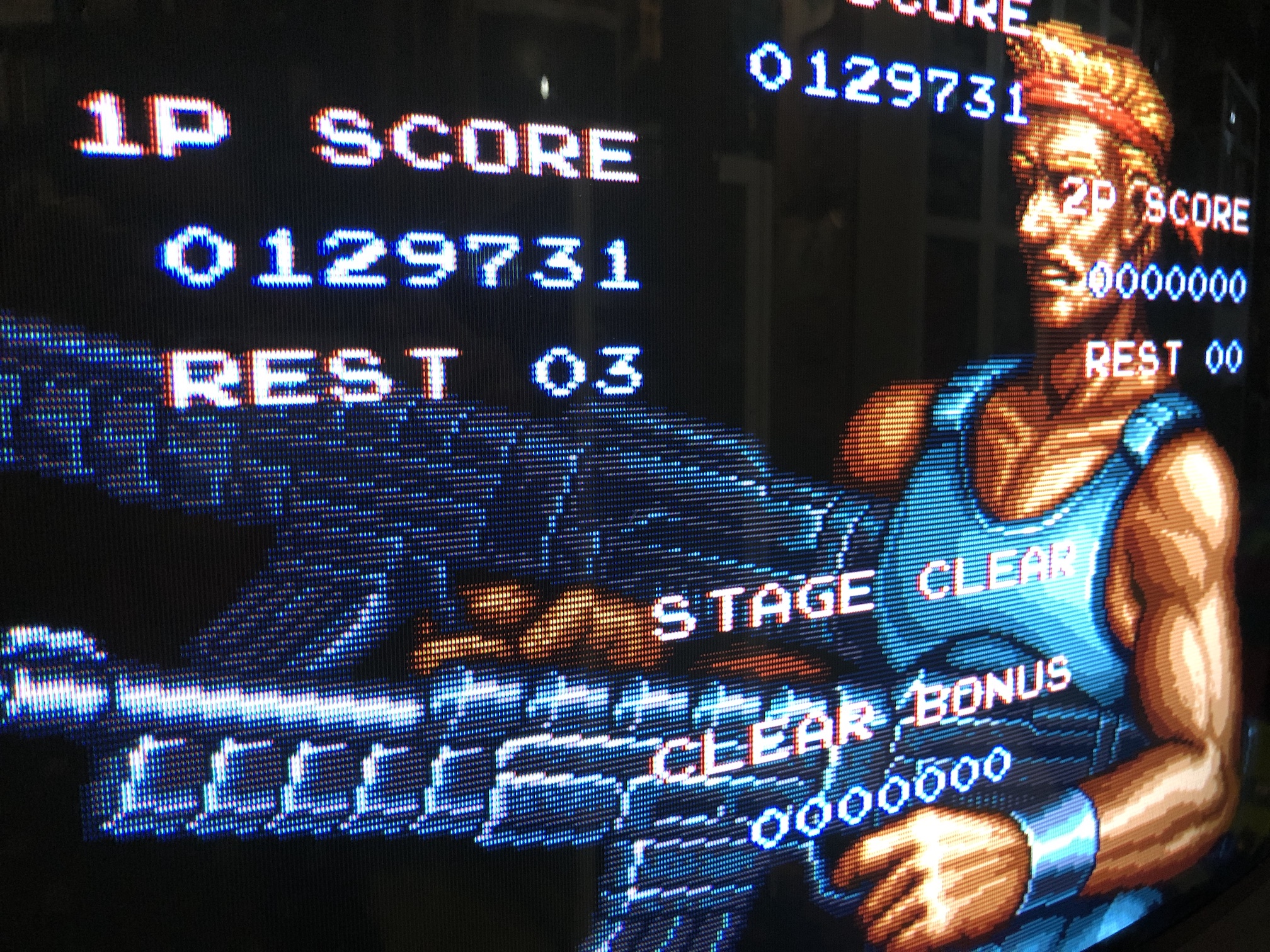
XBOX - UnleashX 
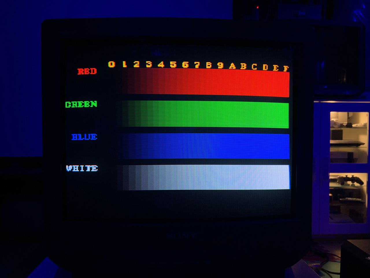
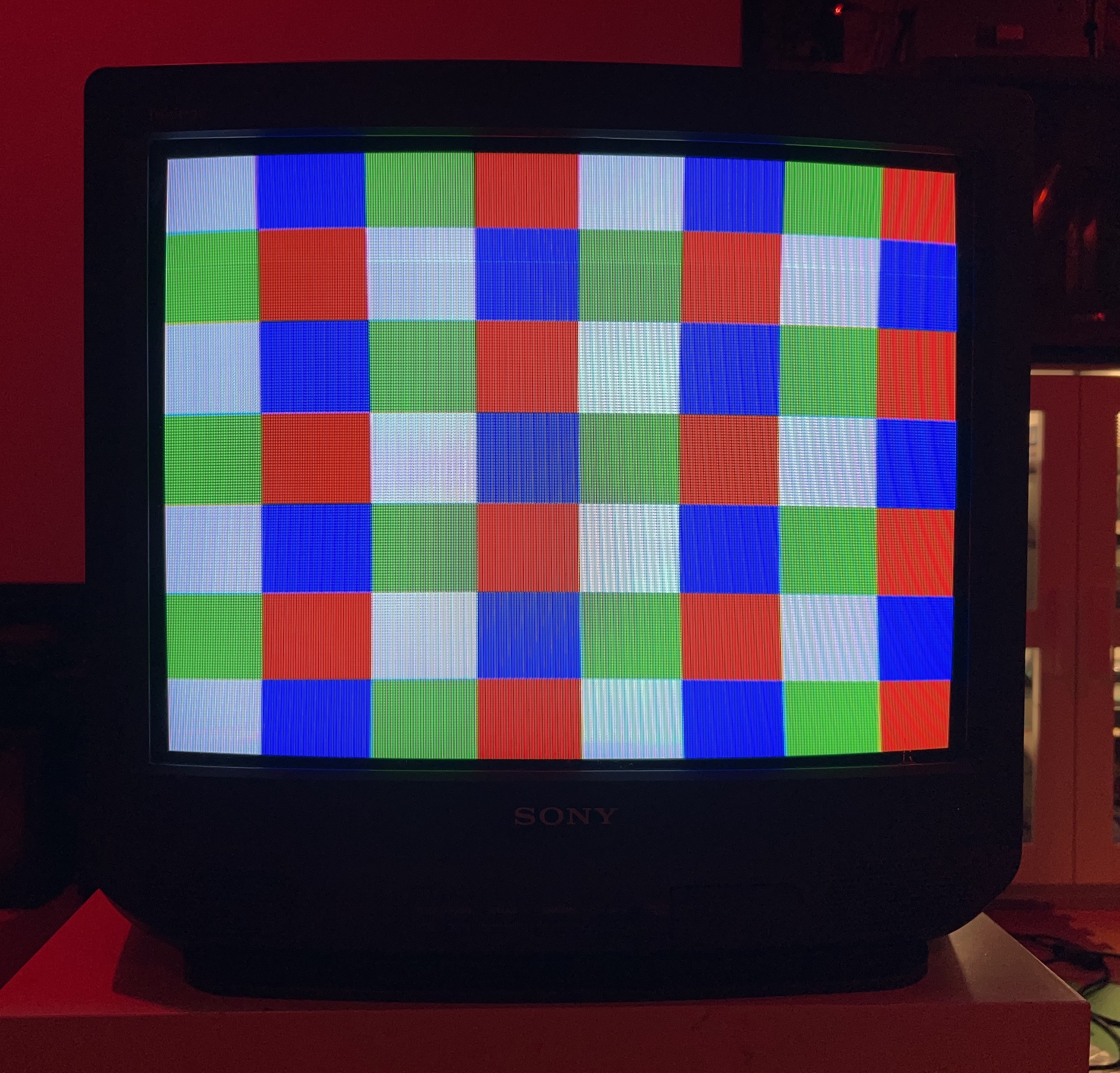
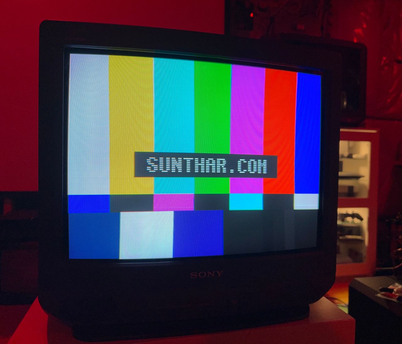
Patterns
Grid 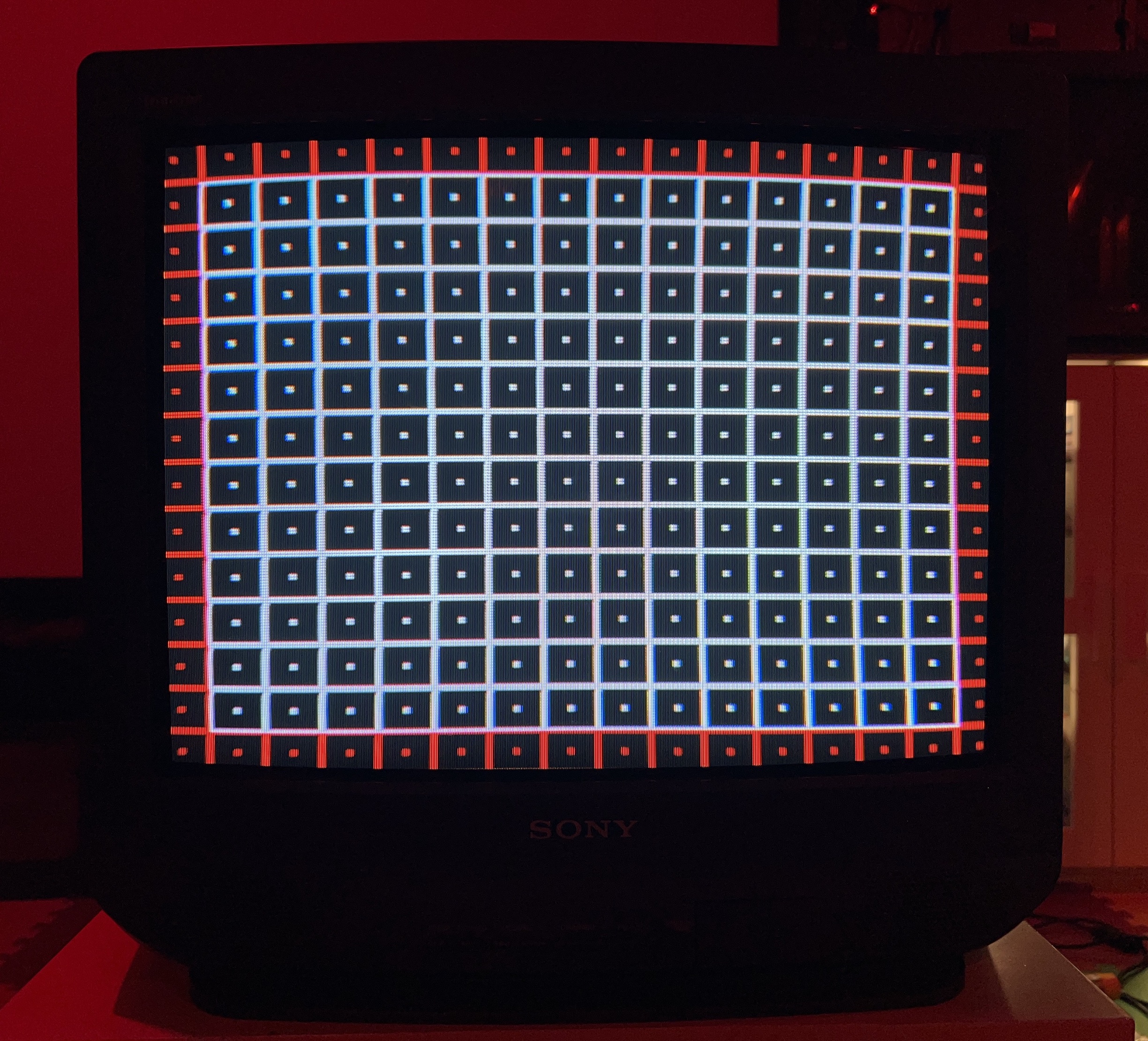
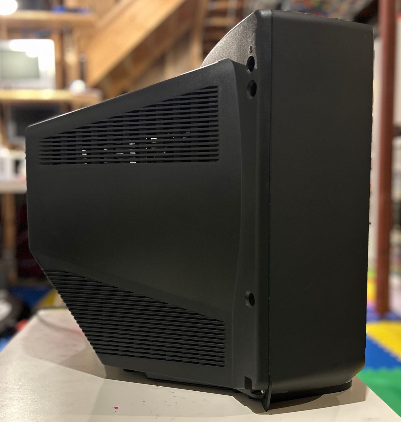
Set Pictures
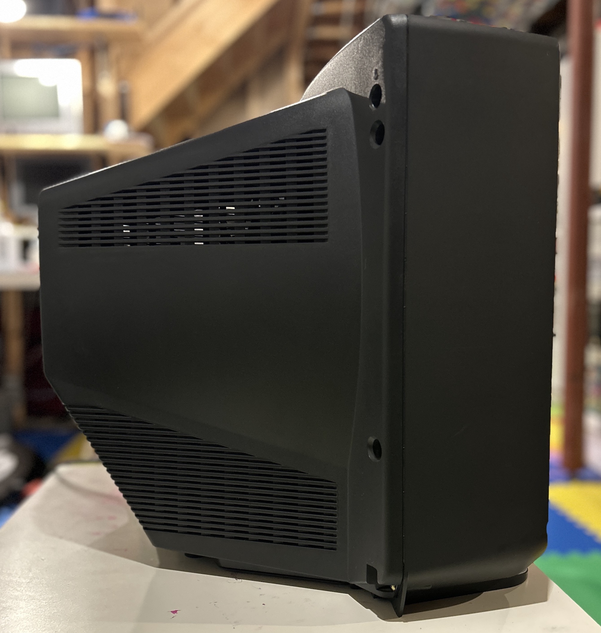
Pictures
Photos by Sunthar
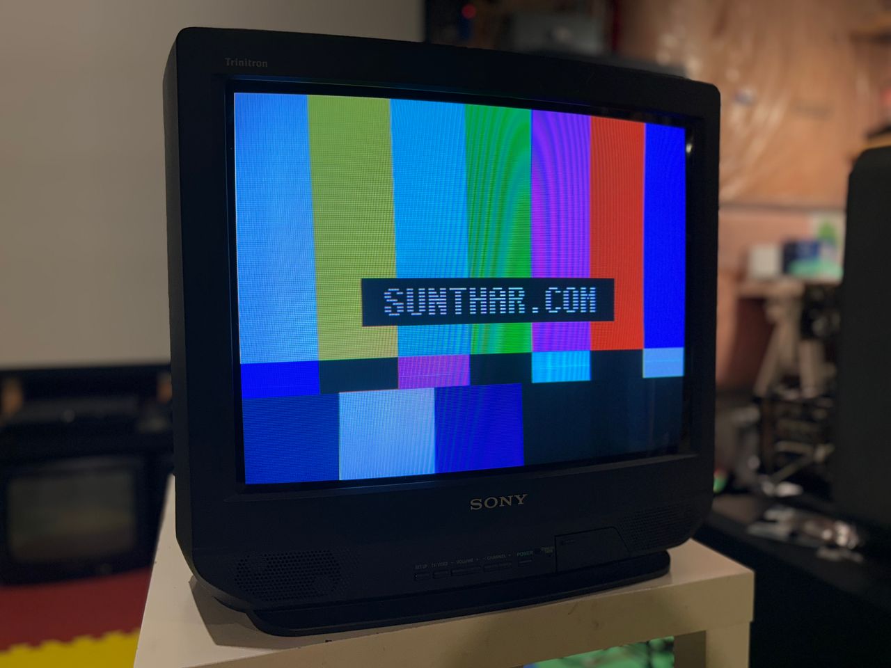
Modifying a Sony KV-20S42 to display a beautiful RGB image.


Reference Photos