JVC AV-27230
JVC AV-27230 CRT RGB mod
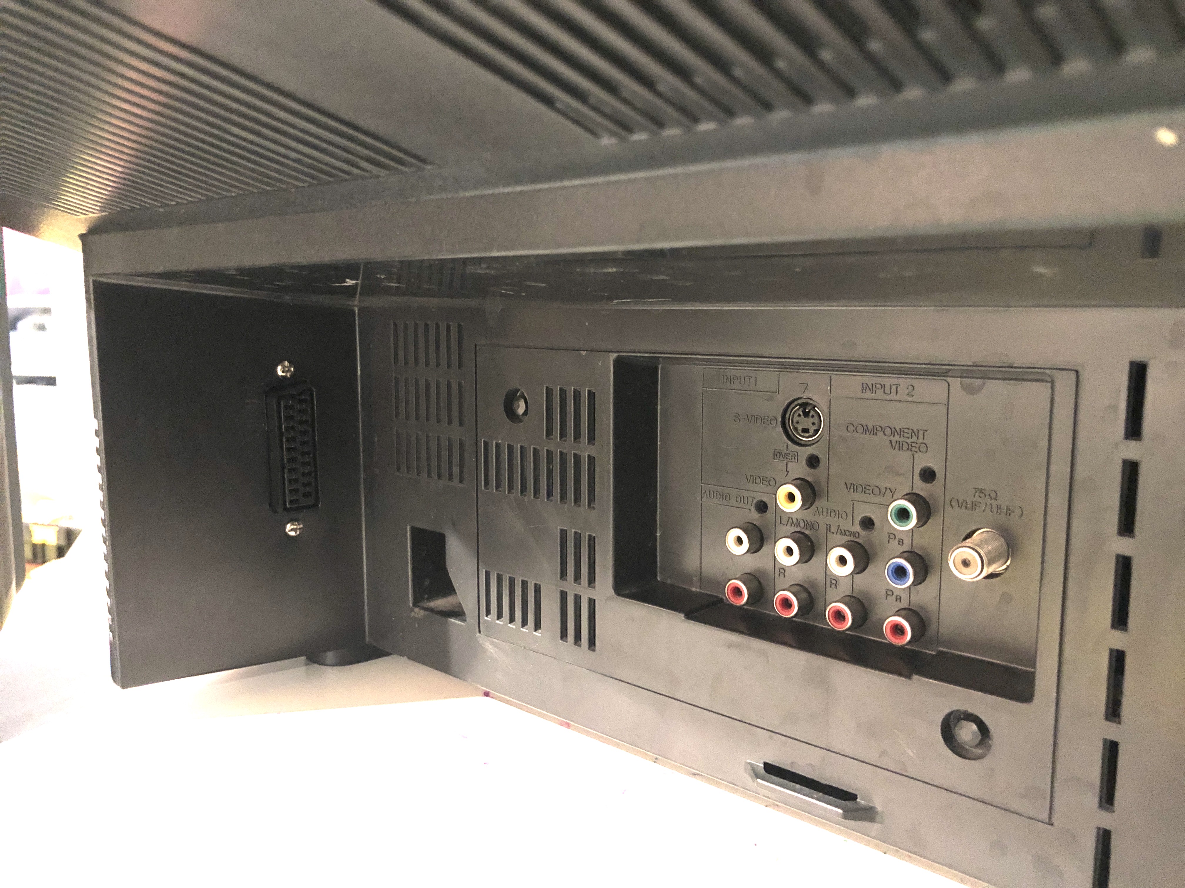
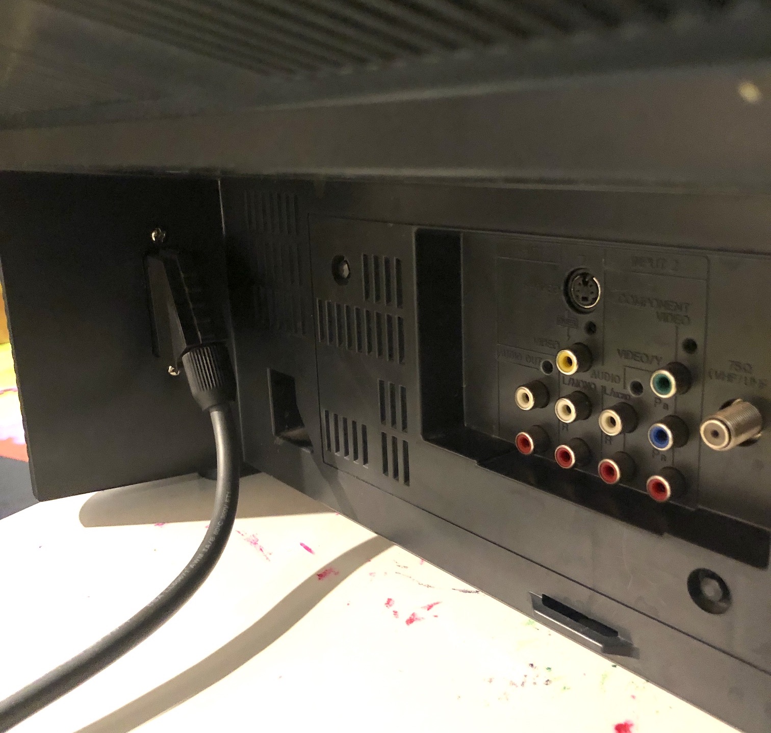
The JVC AV-27230 is a 27" CRT television from the early 2000s, sharing the same high-quality tube and picture performance as the popular JVC D-Series, but with a smaller footprint. It features component, S-Video, and composite inputs, 600 lines of horizontal resolution, a 3-line digital comb filter, and is RGB modifiable.
The tube on this model is exceptional with impressive geometry, and unlike the highly coveted JVC D-Series (e.g. AV-27D201), there were no distracting funhouse scrolling problems observed. Therefore, if you own a JVC curved set that can be RGB modified (some can't be modified), I strongly endorse trying out this modification.
View full CRT details and more mod examples →
In this tutorial, we will be discussing the RGB modification process for the JVC AV-27230 CRT.
Contributors
Thank you to everyone who contributed to this guide:
- Sunthar's Super Store — photos and documentation
- Eli Krause — contributor, CRT specs
CRT safety
Caution
You can die doing this! So read carefully! CRT TV is not a toy. Do not open a CRT TV. If you don't have any prior knowledge about handling high voltage devices, this guide is not for you. CRT TV contains high enough voltage (20,000+ V) and current to be deadly, even when it is turned off.
Plan of attack
Theory
Sometimes it is nice to know the theory behind the mod. I have put this on a separate page. This shows how the various resistor values are calculated.
Manuals and Datasheets
- JVC AV-27230 Service Manual
- JVC AV-27230 Service Manual
- Toshiba TB1253AN Datasheet (Jungle)
- M37272MA-314SP Datasheet (OSD)
Specs
- Year: 2001
- Format: NTSC
- Chassis: FD
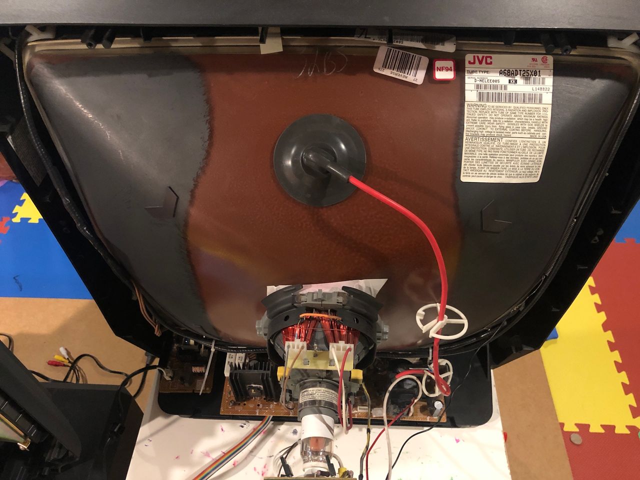
- Tube: Thomson A68ADT25X01
- Jungle Chip: Toshiba TB1253AN
- OSD Chip: M37272MA-314SP
- Screen Size: 20"
- Inputs: Composite, S-Video, RF, Component YPbPr
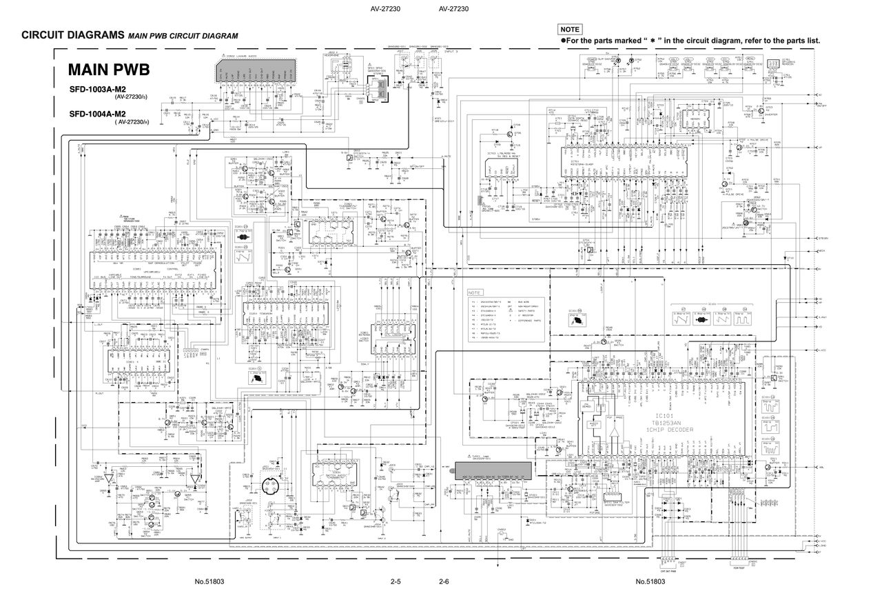
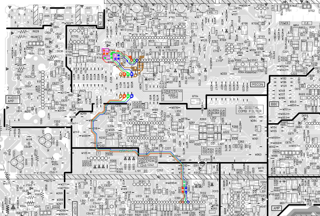
Schematics
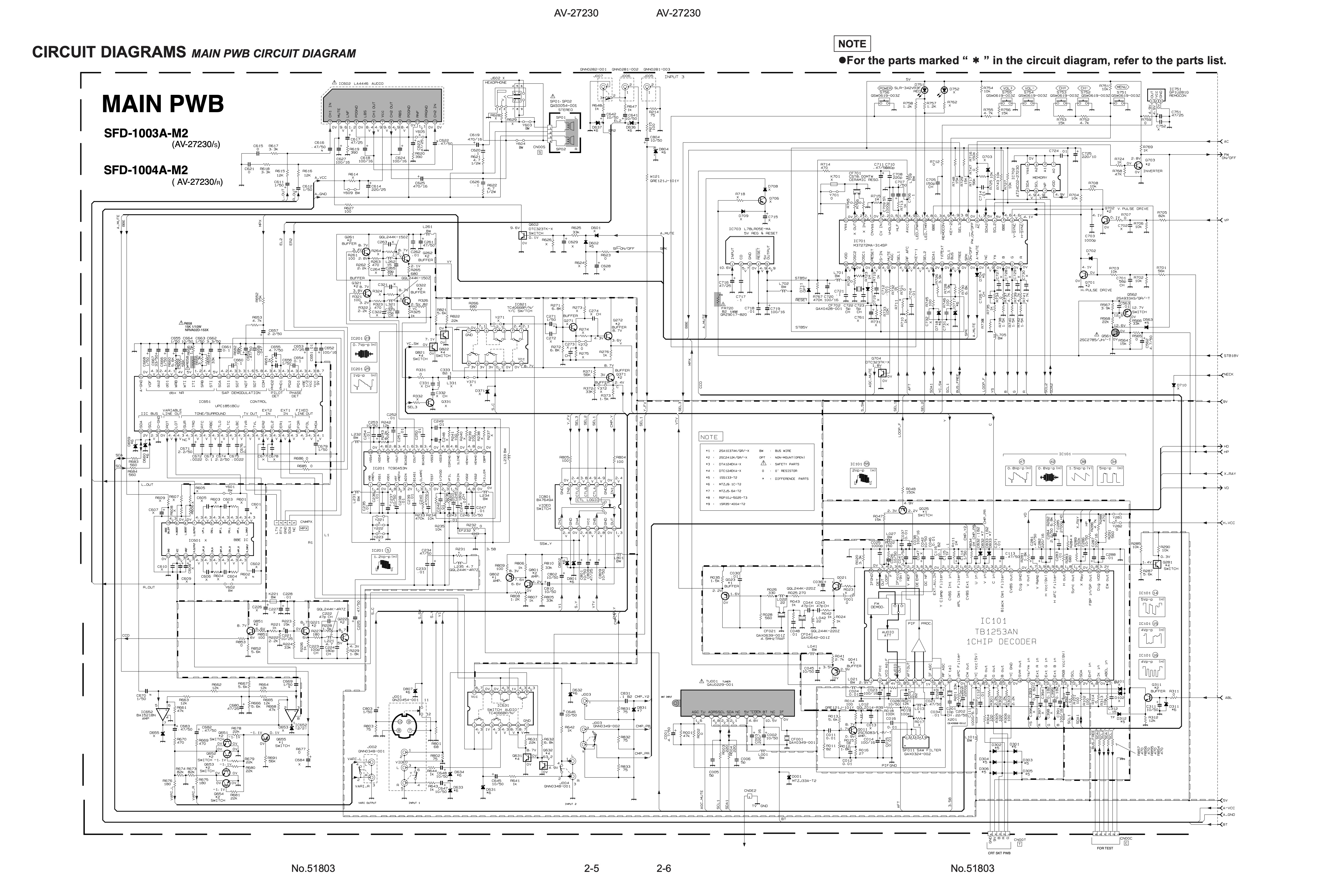
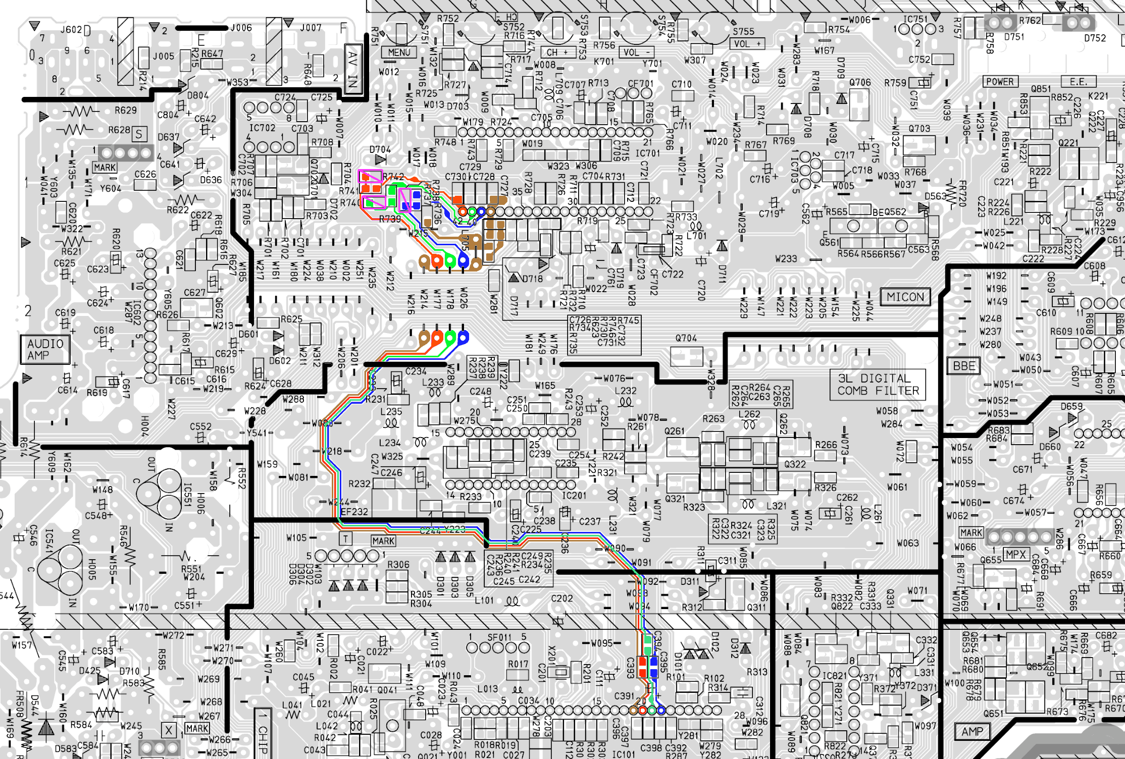
PCB diagram
RGB mux diagram
Performing the mod
Now that you roughly know what needs to be done, prepare for the mod. Place the main chassis on a comfortable place. Make sure you are not putting pressure on the flyback or other components.
STEP 1: Remove the following components
Remove the following components. RGB resistors to the ground. Measure twice and mark before you remove.
- R738 (1.5 kΩ)
- R740 (1.5 kΩ)
- R742 (1.5 kΩ)
Note: It was strange that the chassis did not include a ground resistor for blanking. This ground resistor is shown in the schematics however. To address this issue, a 4.7 kΩ (R10) ground resistor was added to the mux board.
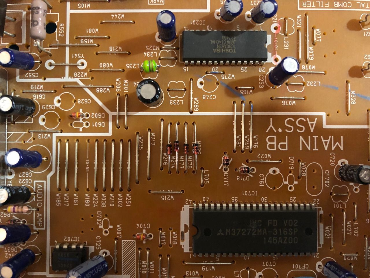
STEP 2: Install diodes to reduce noise
Add 1N4148 diodes by replacing jumpers W177(R), W178(G), W026(B) and W214(Blanking)
- W177
- W178
- W026
- W214
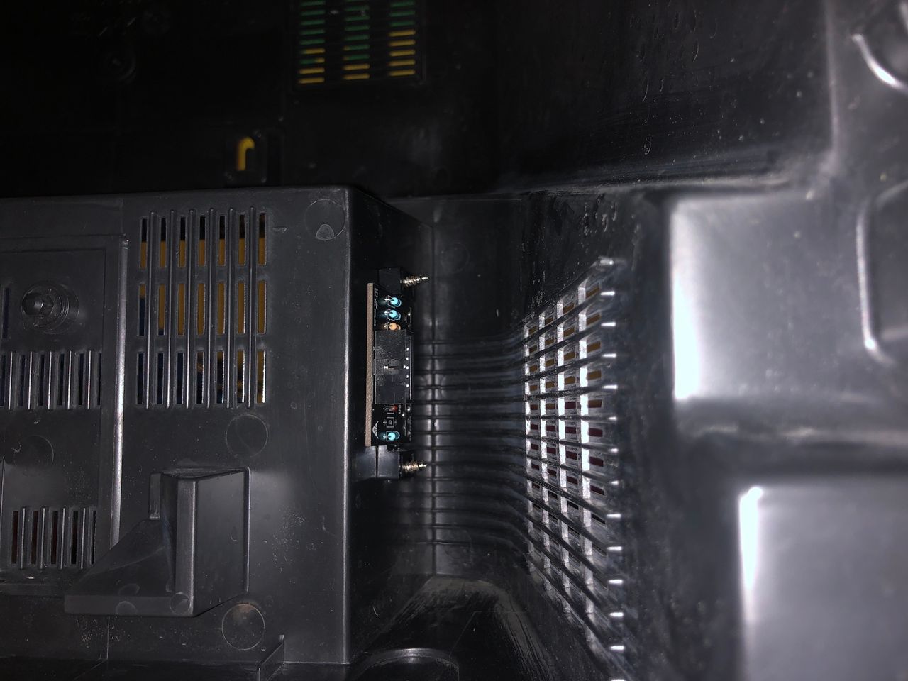
Pay attention to the direction of the diodes. Also, install the diodes on the component side of the chassis, as seen in the picture below.

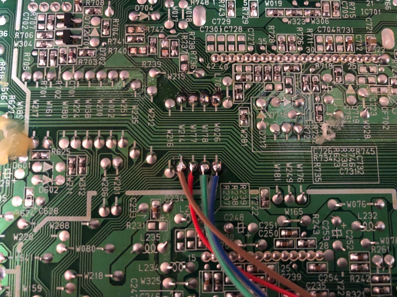
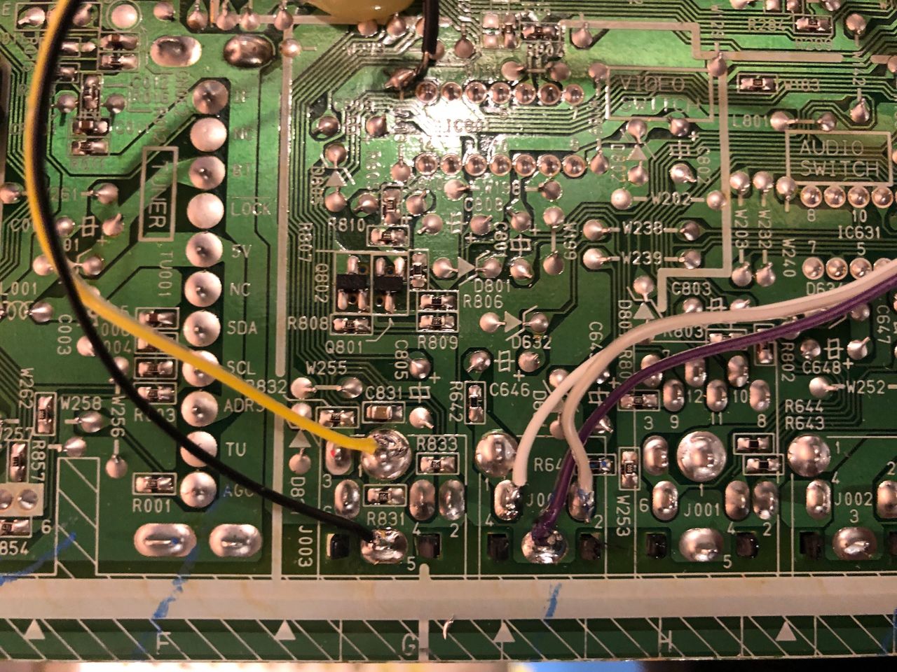
STEP 3: Connect RGBs, Blanking and Audio
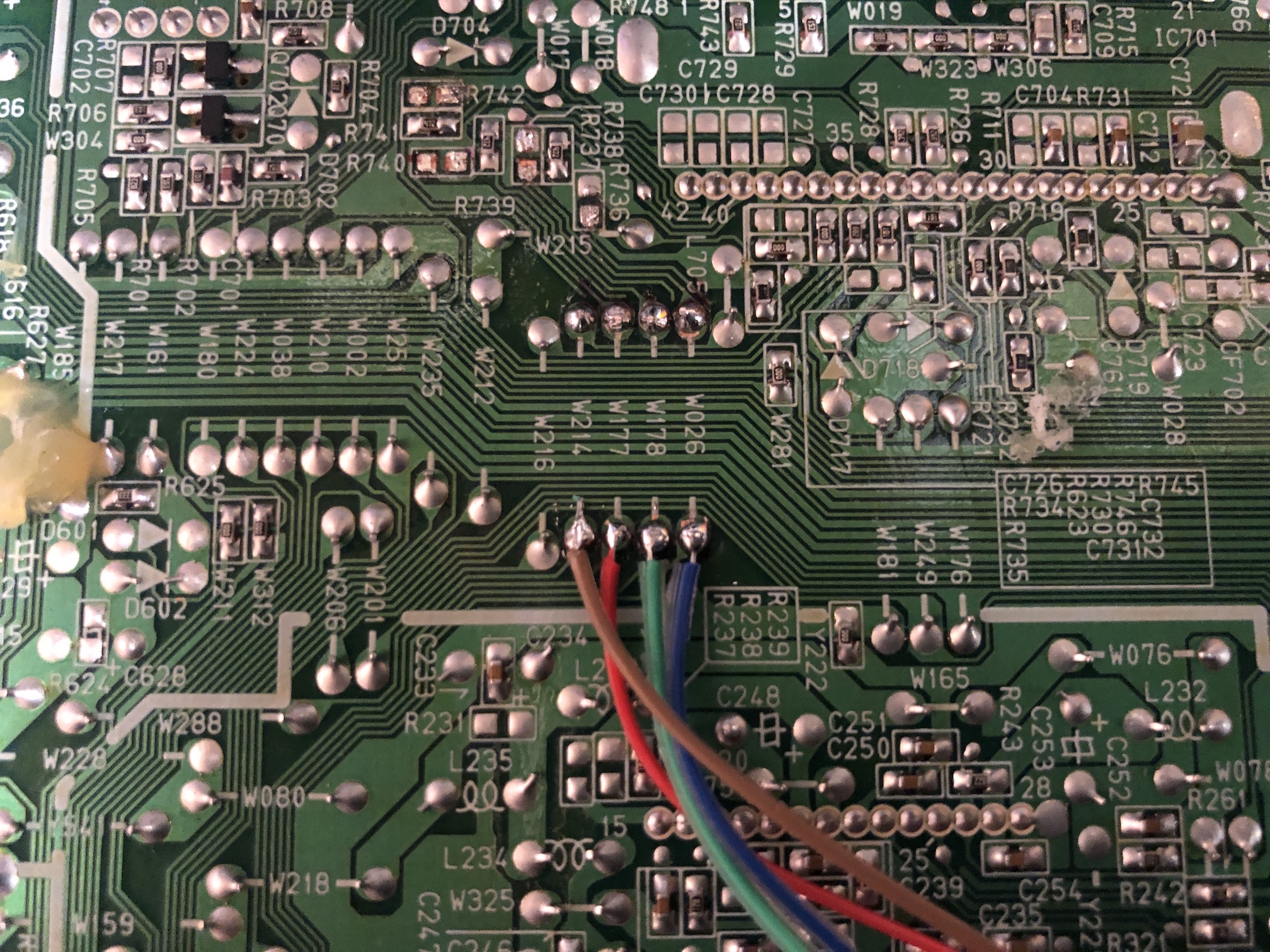
The picture presented below depicts the appropriate placement for soldering the R, G, B, and blanking wires onto the solder side of the chassis. It is crucial to solder them on the correct side of the diode installation location, as illustrated in the image.
The sync was linked to the component luma pin, while the audio was connected to the corresponding left and right audio inputs. It's important to remember that in order for the stereo sound to function properly, a dummy RCA must be inserted into the right channel's red audio RCA port.
The ground wires consist of the purple and black wires, with an additional redundant ground wire in orange. The latter was deliberately cut off and insulated, taking care to avoid any short circuits on the main chassis.

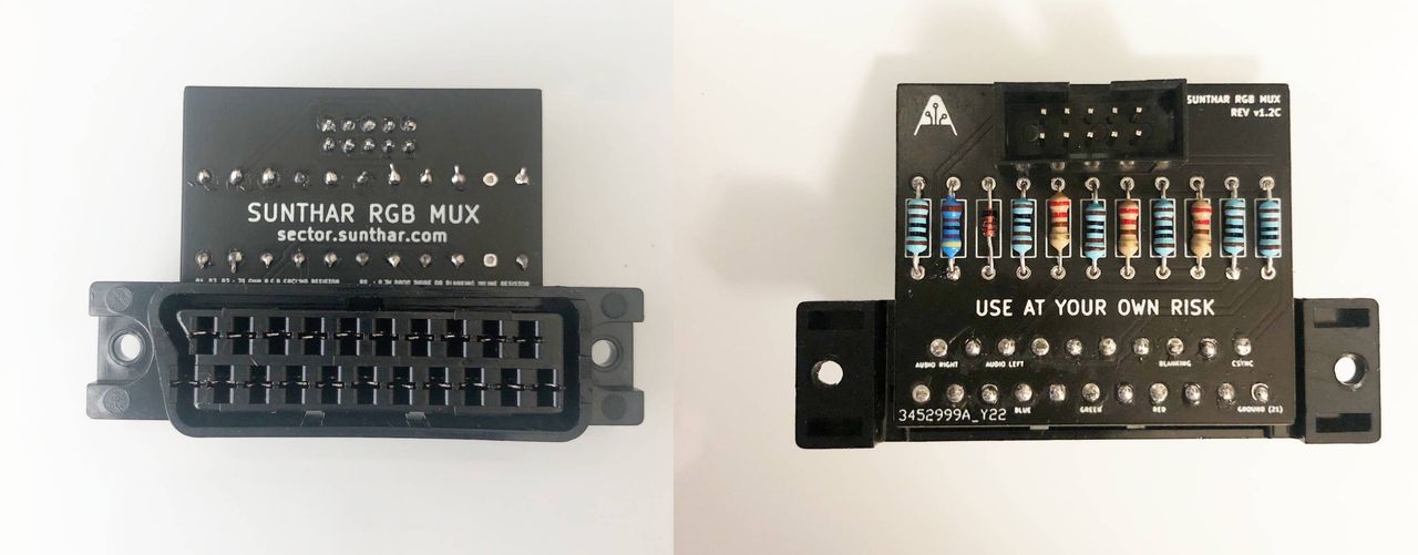
STEP 4: Build your mux board
This mod uses the RGB mux board. This is optional, but will make your mod easier and stable. You can also create the circuit presented in the schematics above without the board. Please also checkout the mux calculator to play with your own values.
| Component | Value |
|---|---|
| RGB/OSD inline resistor (chassis) | 4.7kΩ |
| Removed RGB/OSD resistor (chassis) | 1.5kΩ |
| RGB inline diode method (chassis) | Yes |
| RGB termination (R1, R2, R3) | 220Ω |
| RGB inline (R4, R5, R6) | 1kΩ |
| Audio LR (R7, R8) | 1kΩ |
| Blanking Ground Resistor (R10) | 4.7kΩ |
| Blanking Resistor (R11) | 1kΩ |
This mod uses the RGB mini mux board (Rev C)

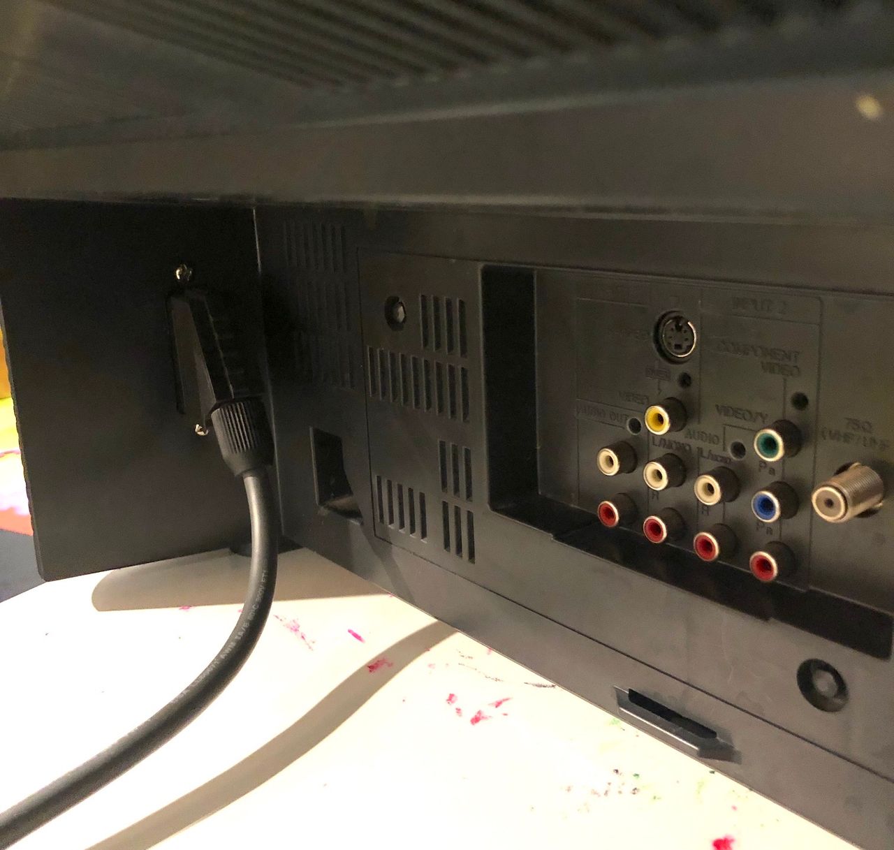
STEP 5: Attach the female SCART connector to TV
Creating a SCART cutout and mounting it is an art. I have a dedicated section for it.
How to create and mount a SCART female plug?
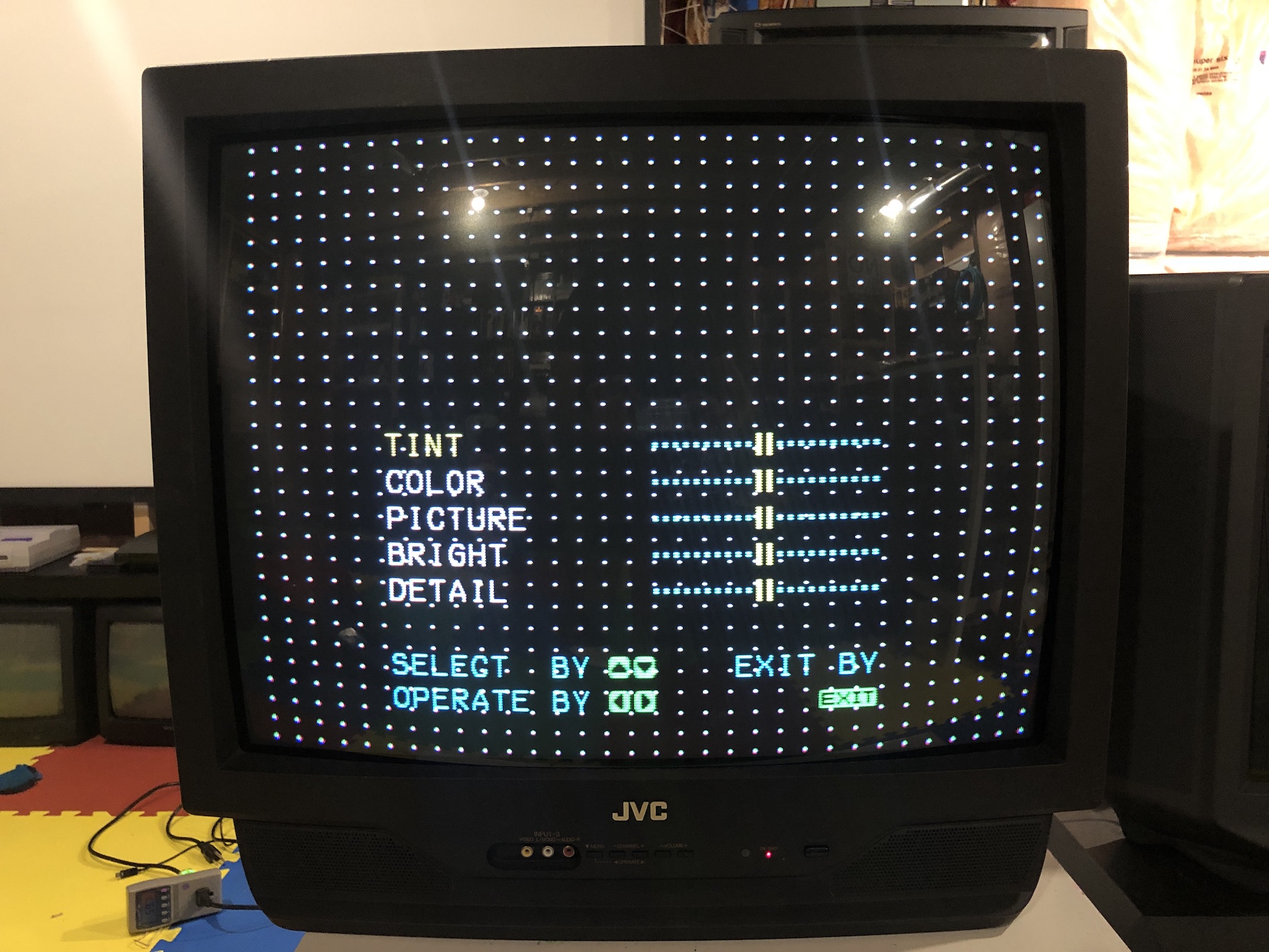
Remote control and service menu
- Press the
SLEEP TIMERkey and set theSLEEP TIMERfor0 MIN - While the
SLEEP TIMERis displaying on the CRT, do the below - Immediately press the
DISPLAYkey and theVIDEO STATUSkey of the remote control unit at the same time. - Then enter the
SERVICE MENUscreen shown in figure.
Pictures
OSD mux overlay
Games
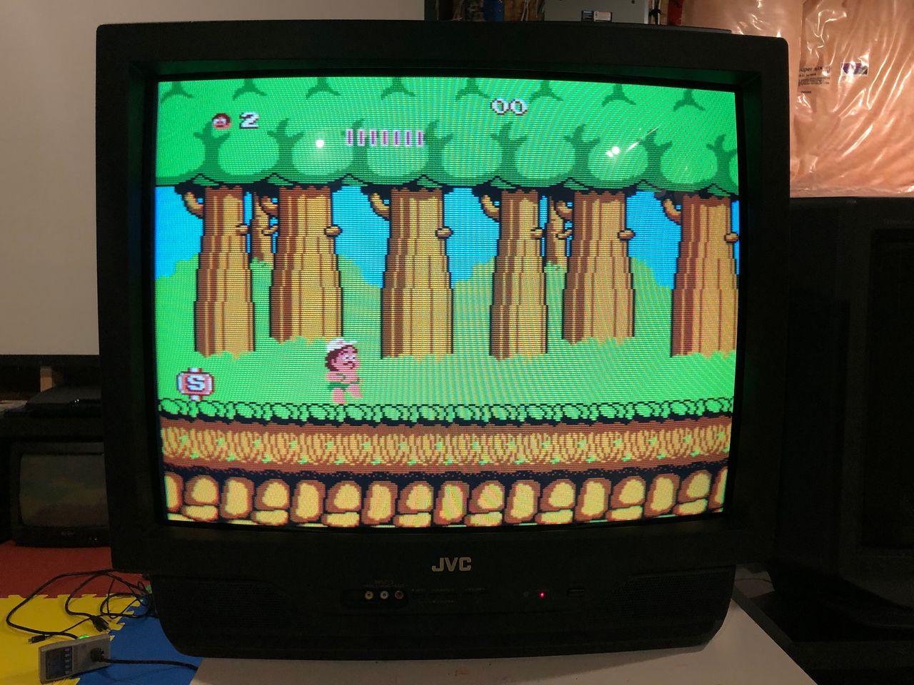
NES - Adventure Island 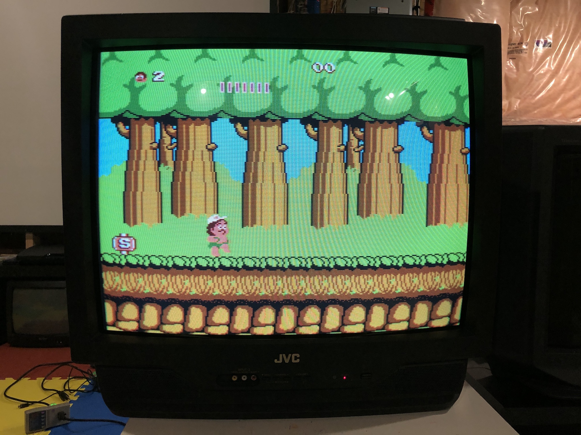
SNES - Super Metroid 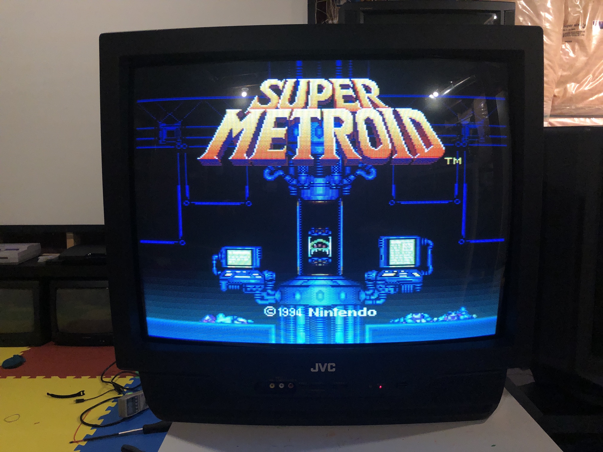
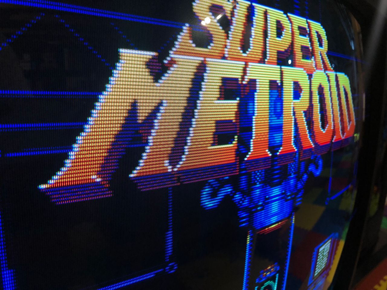
SNES - Super Metroid closeup 
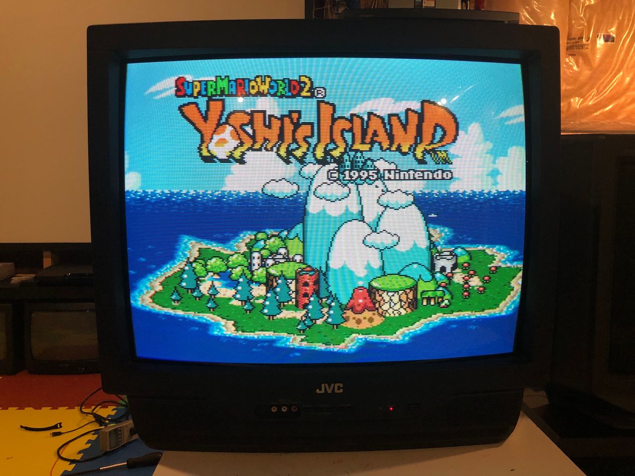
SNES - Yoshi's Island 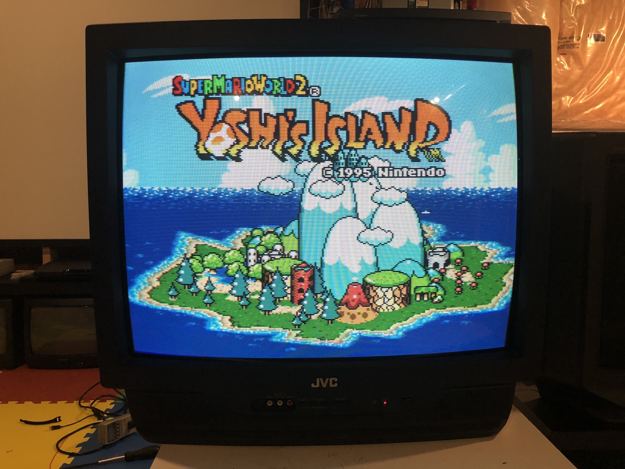
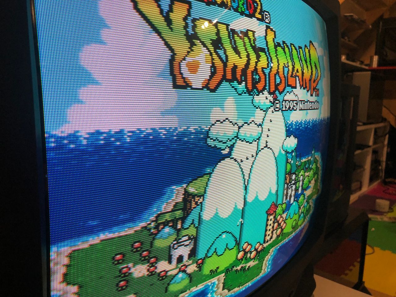
SNES - Yoshi's Island closeup 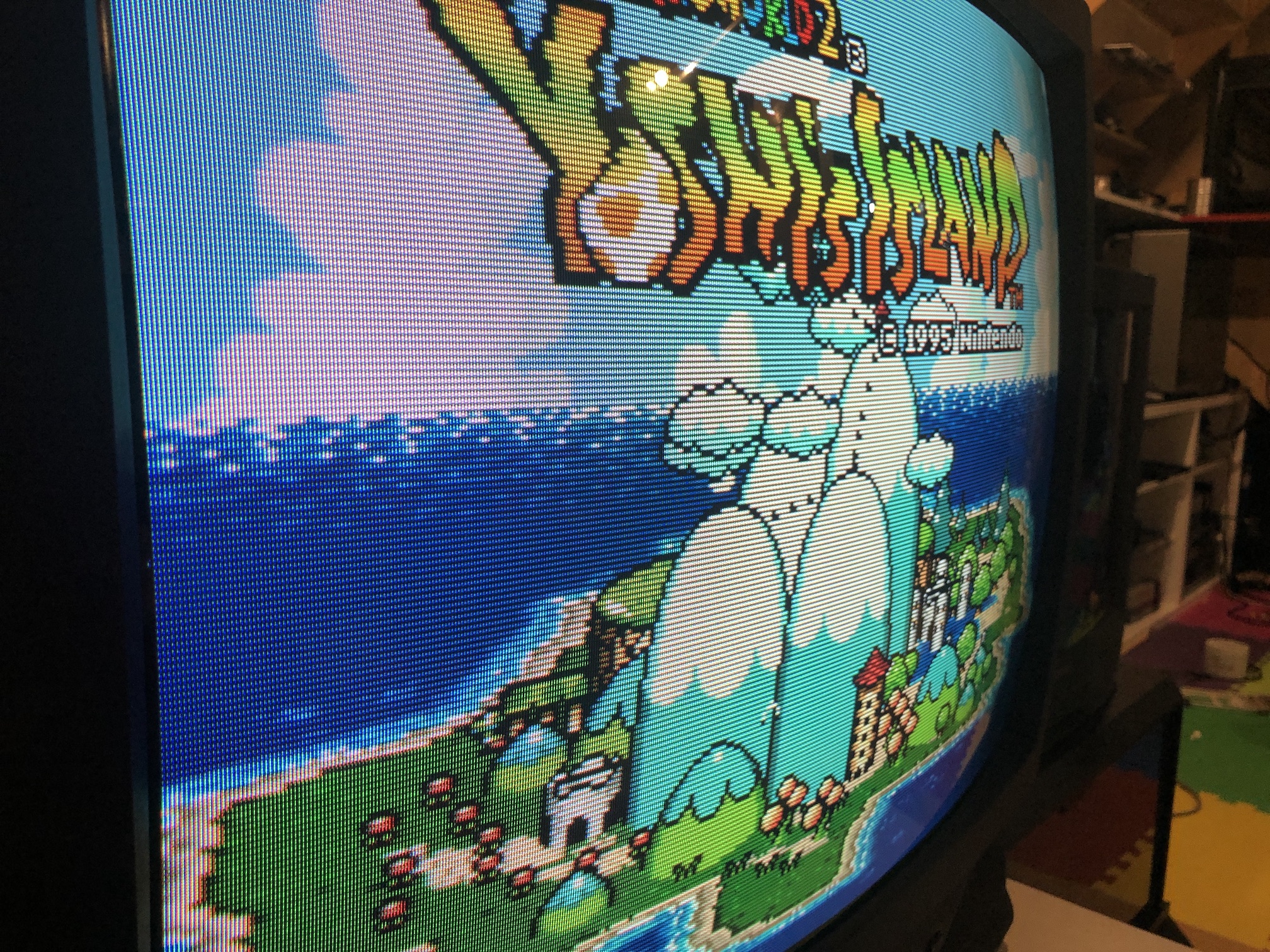
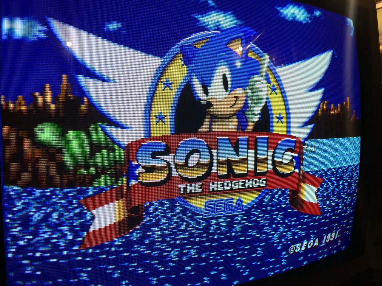
SEGA Genesis - Sonic closeup 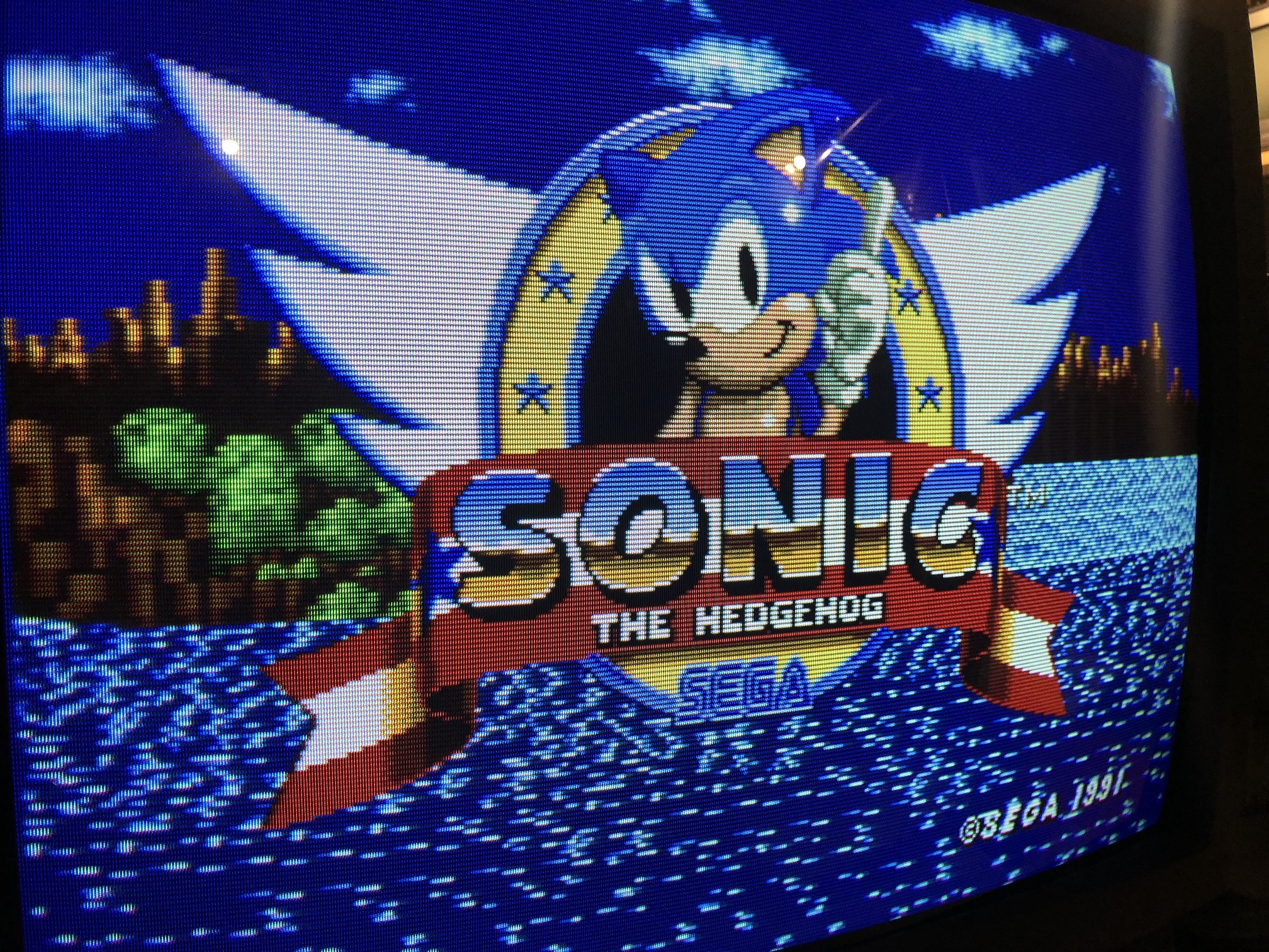
PS2 - Tombraider closeup 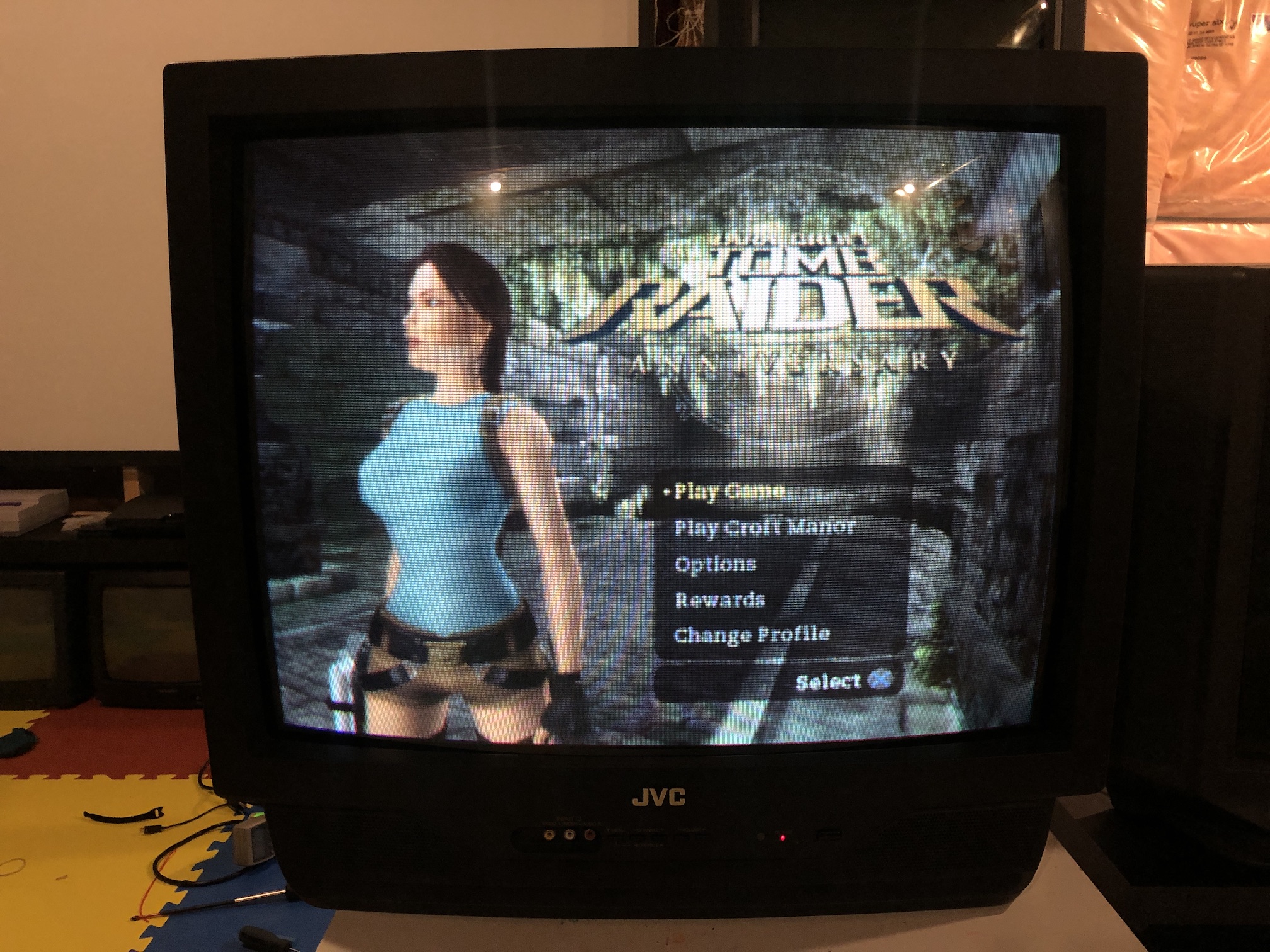
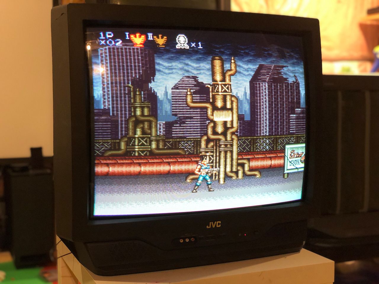
SNES - Contra 3 closeup 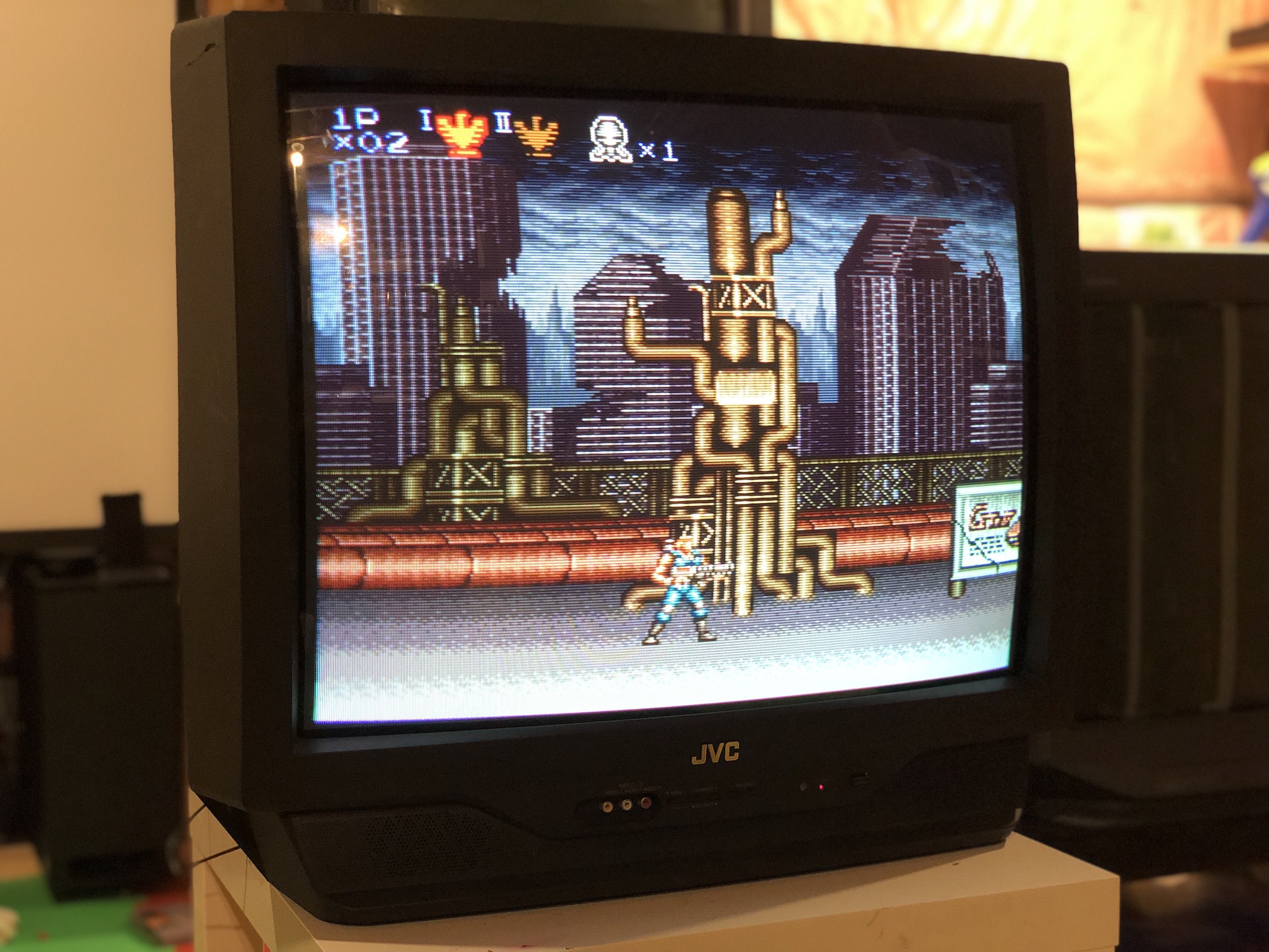
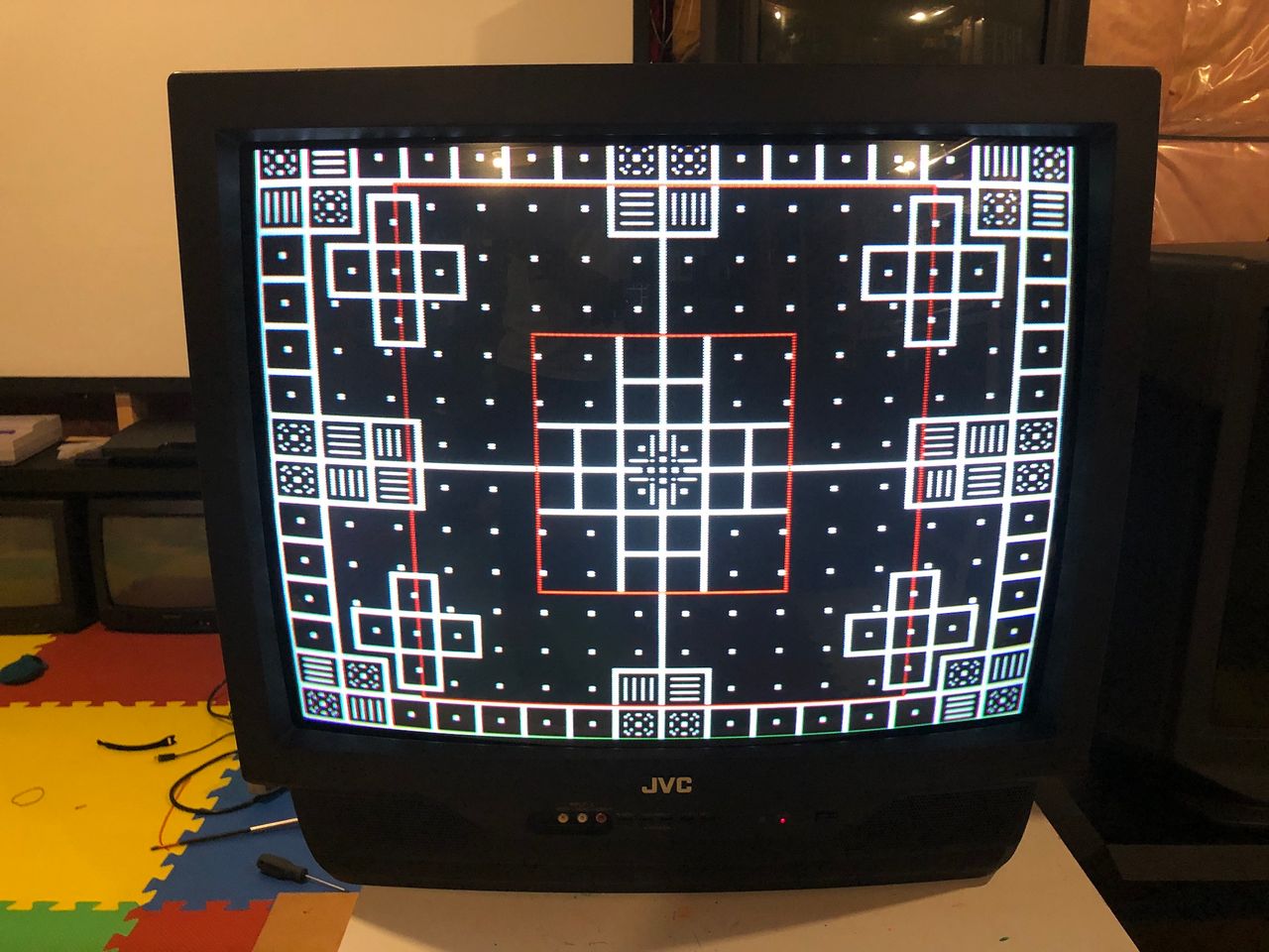
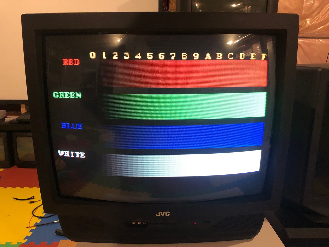
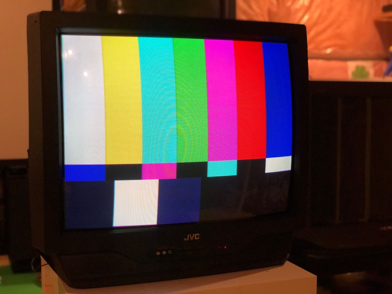
Patterns
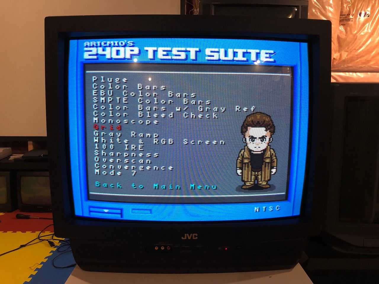
Monoscope 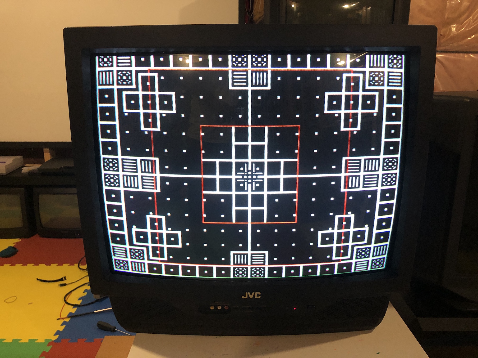
RGB colors 
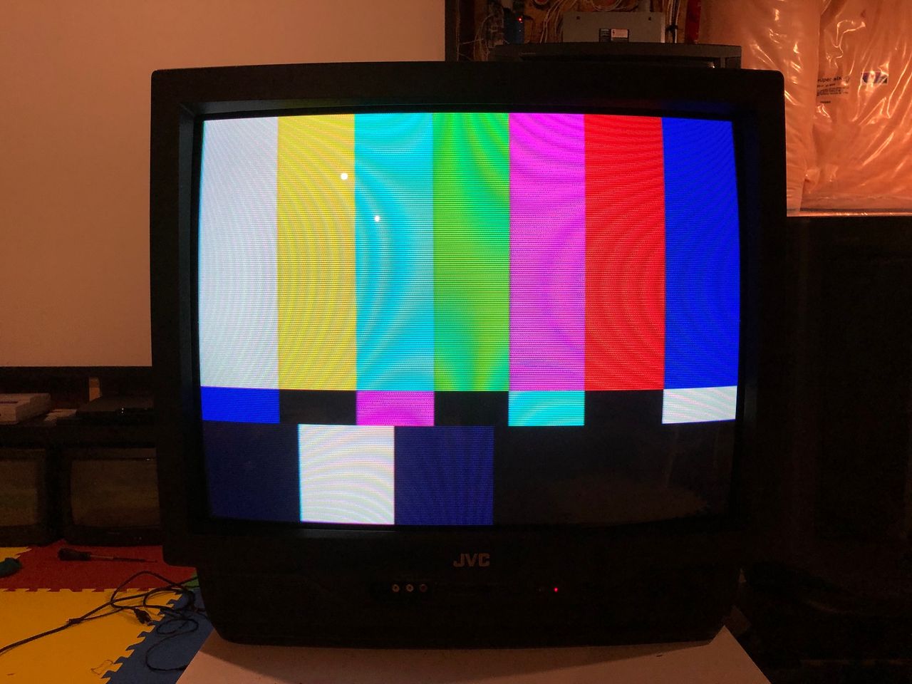
SMPTE 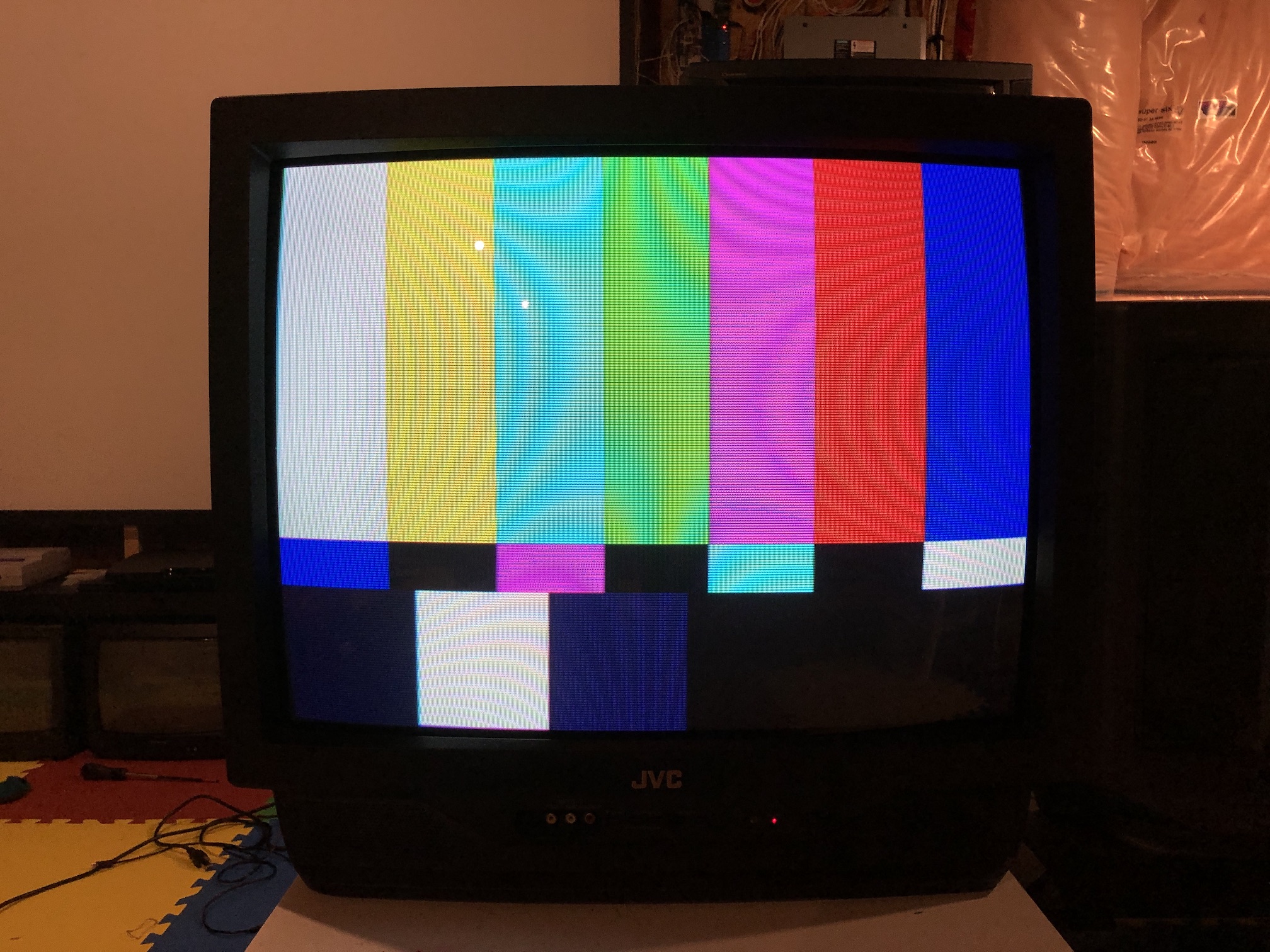
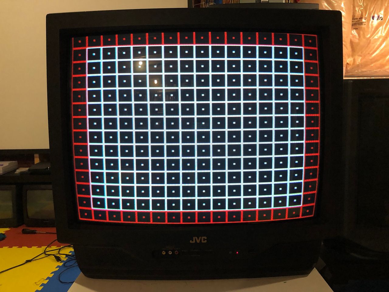
240p Grid 
CRT
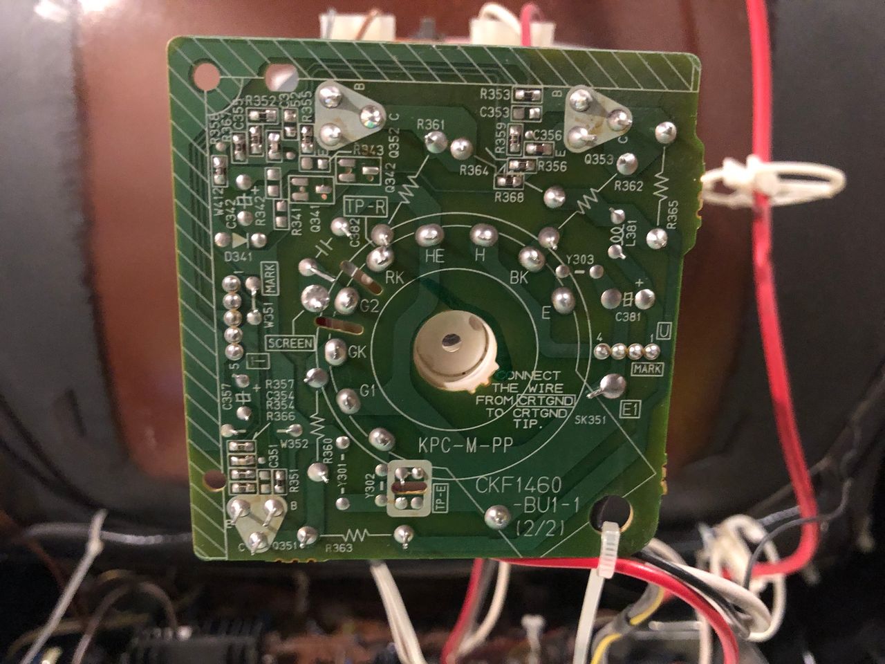
Neck board 
Tube 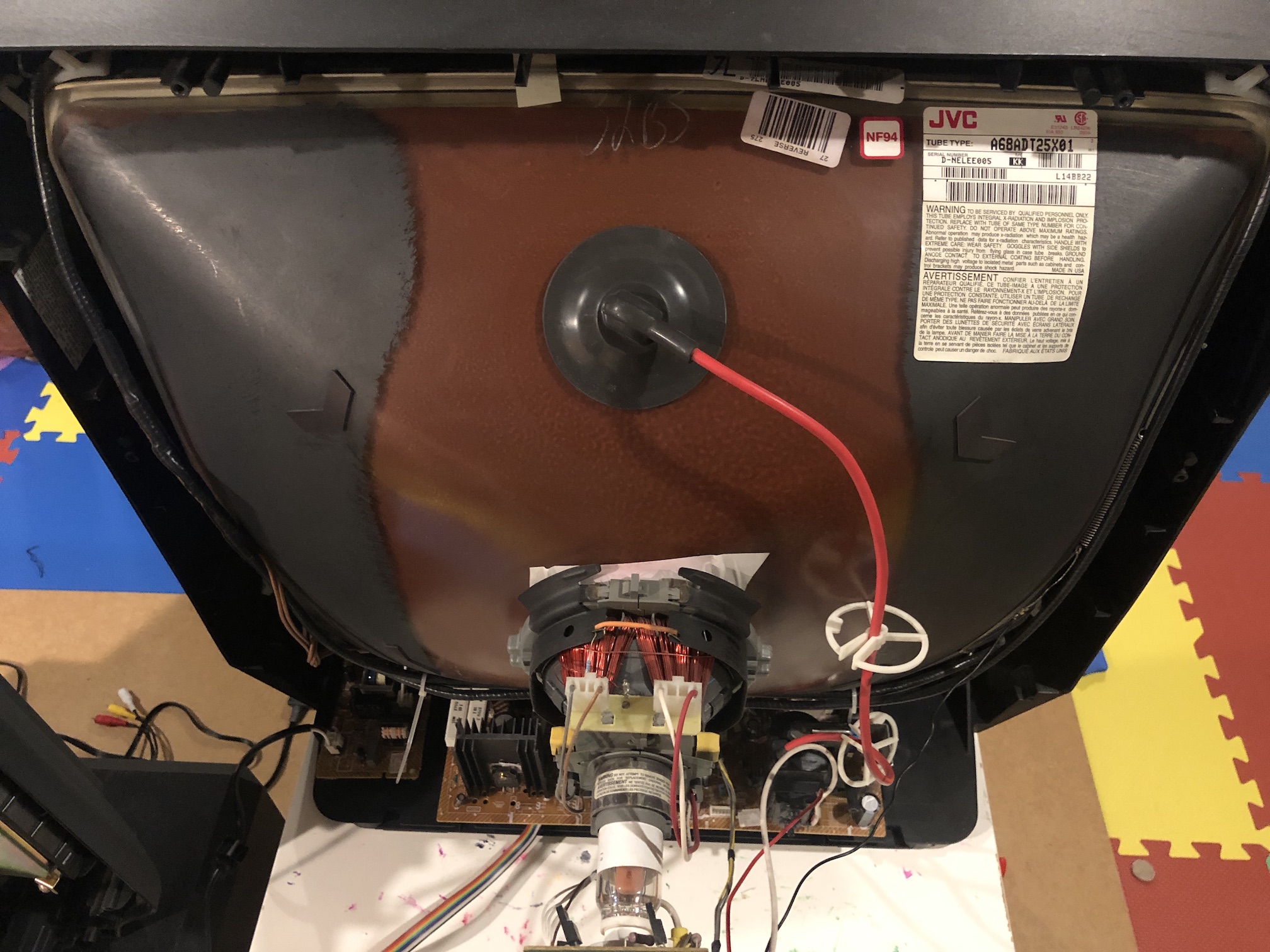
Pictures
Photos by Sunthar's Super Store


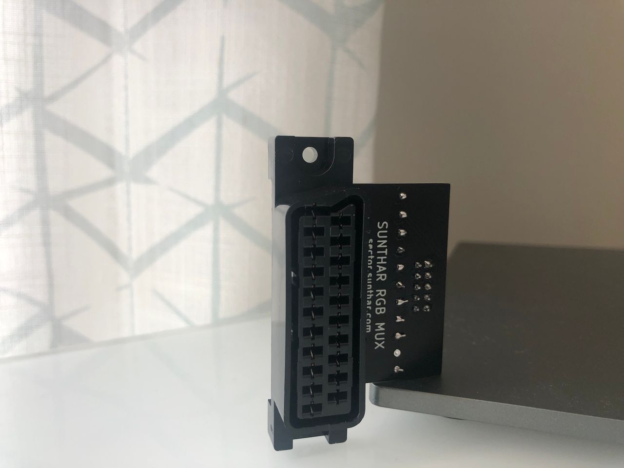
1.3C Sunthar RGB mux board