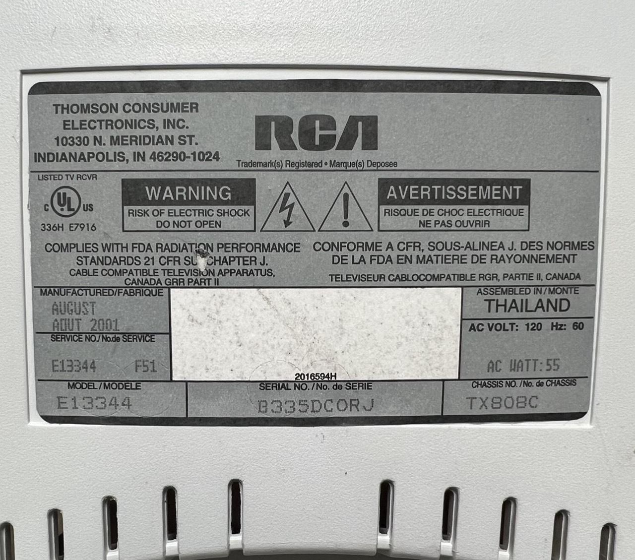
RCA E13344
RCA E13344 CRT RGB mod
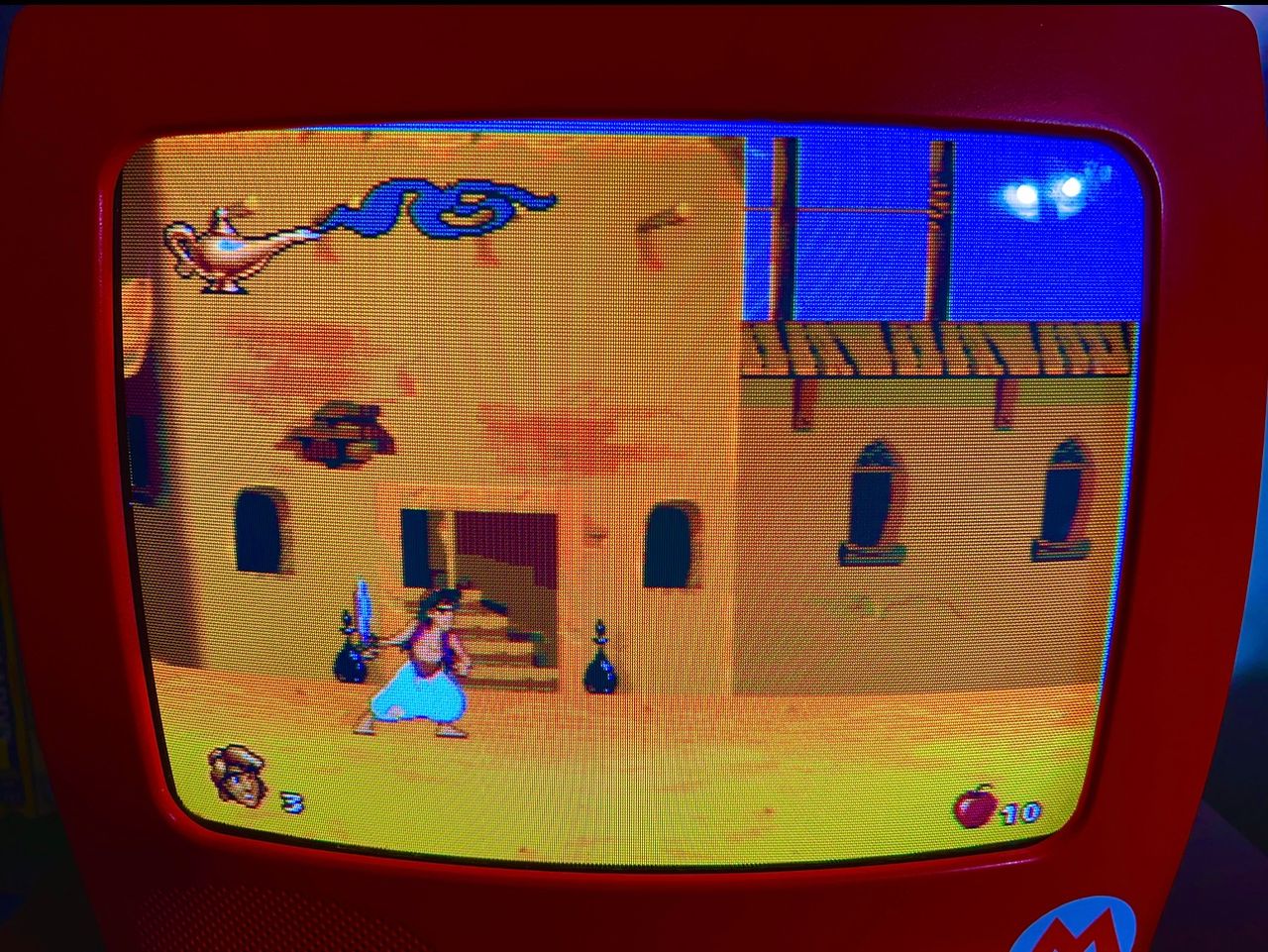
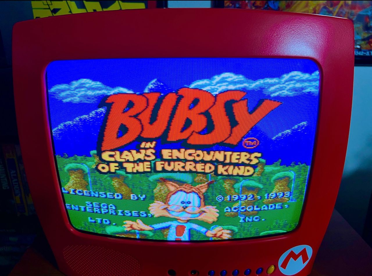
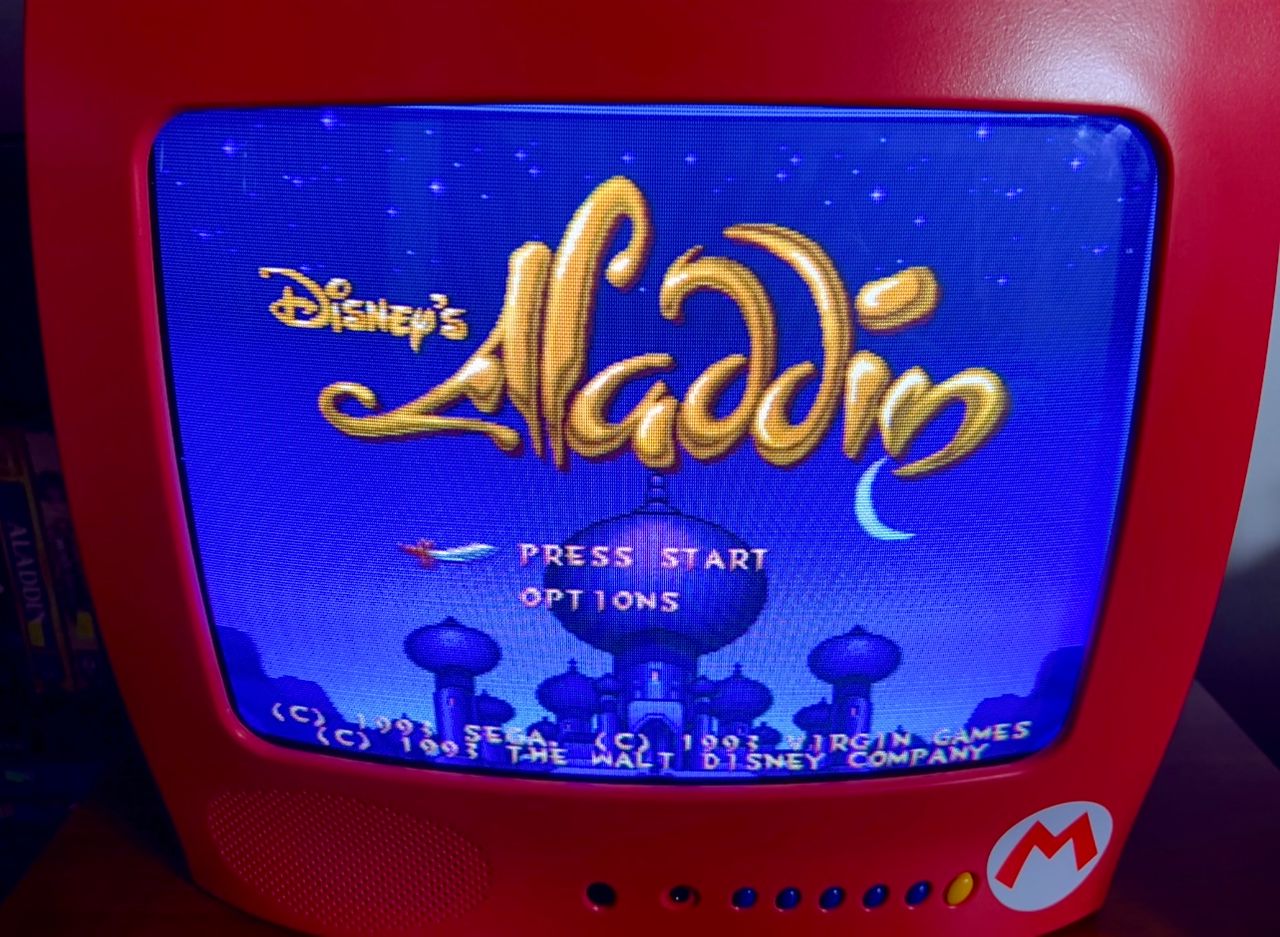
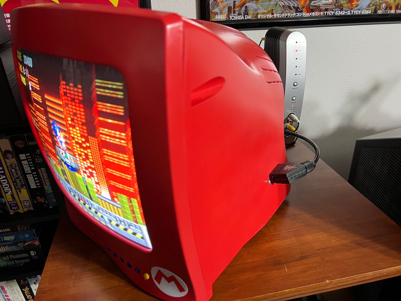
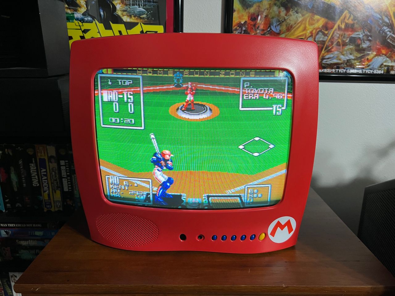
RCA 13" CRT, advertised as the Kitchen TV. This is fortunately RGB modifiable.
View full CRT details and more mod examples →
Contributors
Thank you to everyone who contributed to this guide:
- Mike Morisette — contributor, CRT specs from CRT Database.
- Brandon Burns — contributor, RGB mod article
CRT safety
Caution
You can die doing this! So read carefully! CRT TV is not a toy. Do not open a CRT TV. If you don't have any prior knowledge about handling high voltage devices, this guide is not for you. CRT TV contains high enough voltage (20,000+ V) and current to be deadly, even when it is turned off.
Plan of attack
Manuals and Datasheets
- RCA E13344 User Manual
- Toshiba TA1268N Datasheet (Jungle) — Available for Pro Users only. See CRT details for access.
Specs
- Year: 2003
- Format: NTSC
- Chassis: TX808B
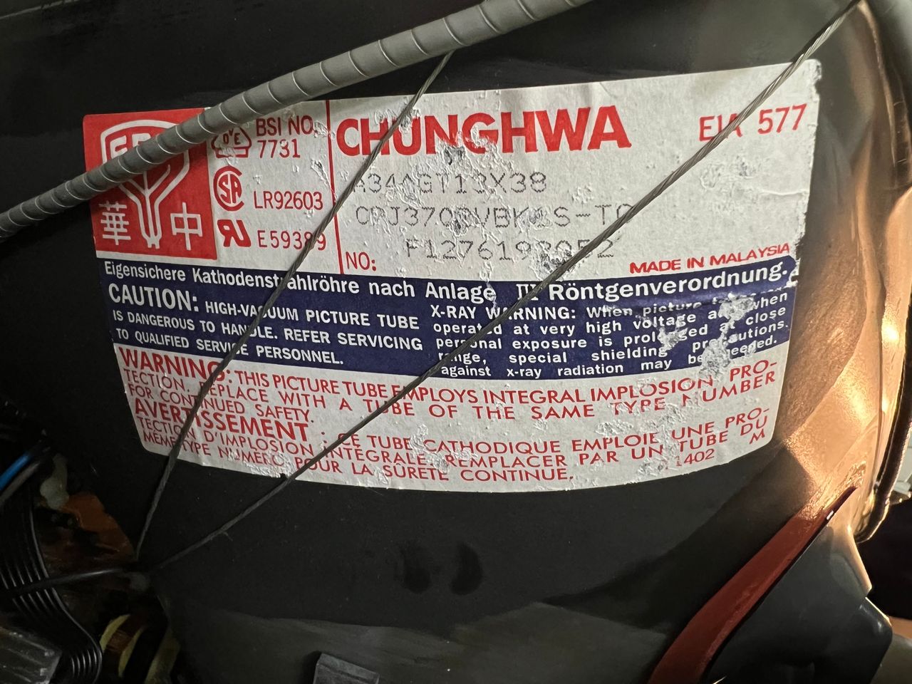
- Tube: Thai CRT Co. A34JXV70X14
- Jungle Chip: Toshiba TA1268N
- OSD Chip:
- Screen Size: 13"
- Inputs: Composite, RF
RGB mux diagram
Prepare the mux diagram. If you are building your own circuit, this diagram should help.
Performing the mod
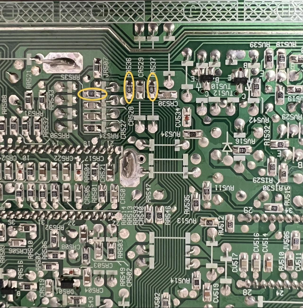
STEP 1: Remove the following components
Remove the following 820Ω resistors that are connected to the ground.
- RR535
- RR536
- RR537
STEP 2: Add RGB and blanking diodes
This step helps reduce interference. Especially the diode on blanking helps prevent the blanking current from reaching the OSD chip. This is known to cause ringing artifacts.
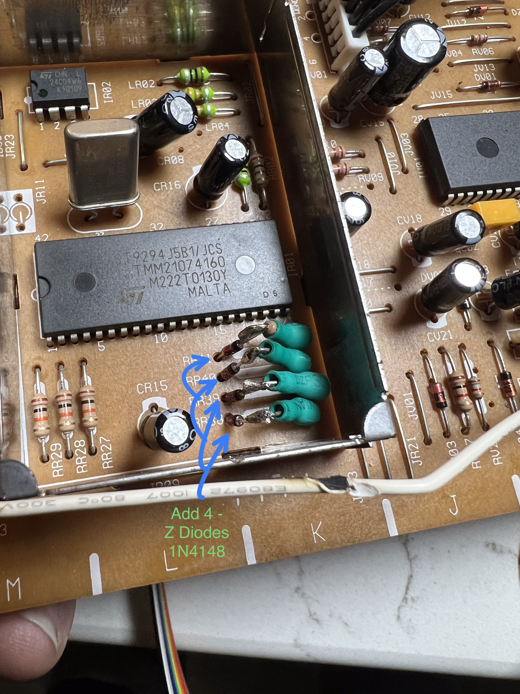
4 diodes added on chassis by lifting RR38, RR39, RR40, RR41.
It's important to note the resistor leg that needs to be lifted and the direction the diode stripe should point. Ignoring this will result in improper OSD muxing. Refer to the mux diagram above.
STEP 3: Connect RGB and Blanking
Picture below shows where the RGB and blanking wires should be soldered.
![]()
Solder wires 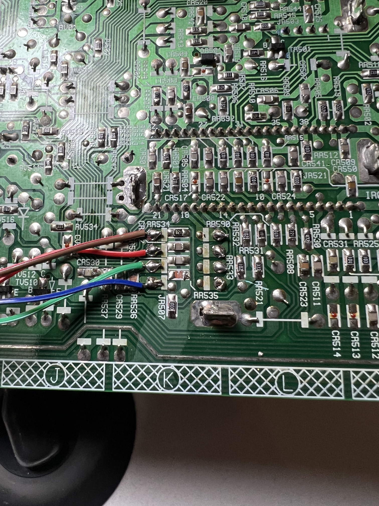
STEP 4: Audio, Sync and Ground
Composite Sync, Audio and Ground wires should be connected.
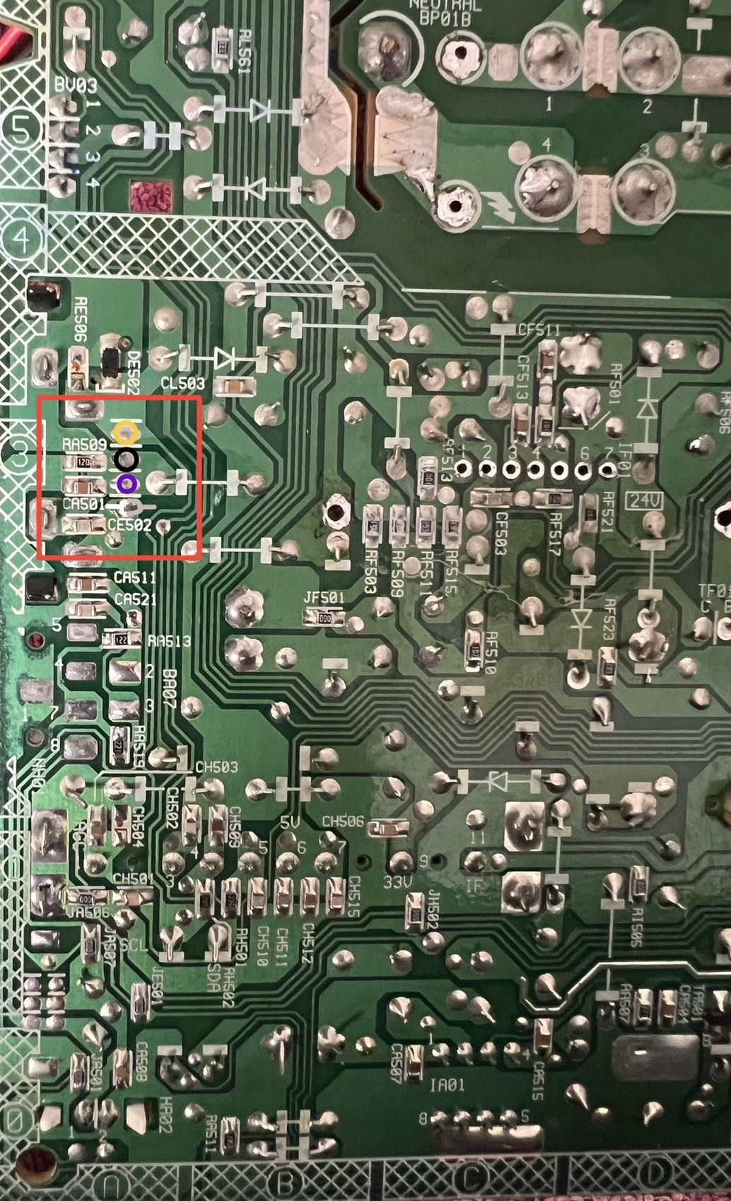
Connect both grey and white wires together for mono audio
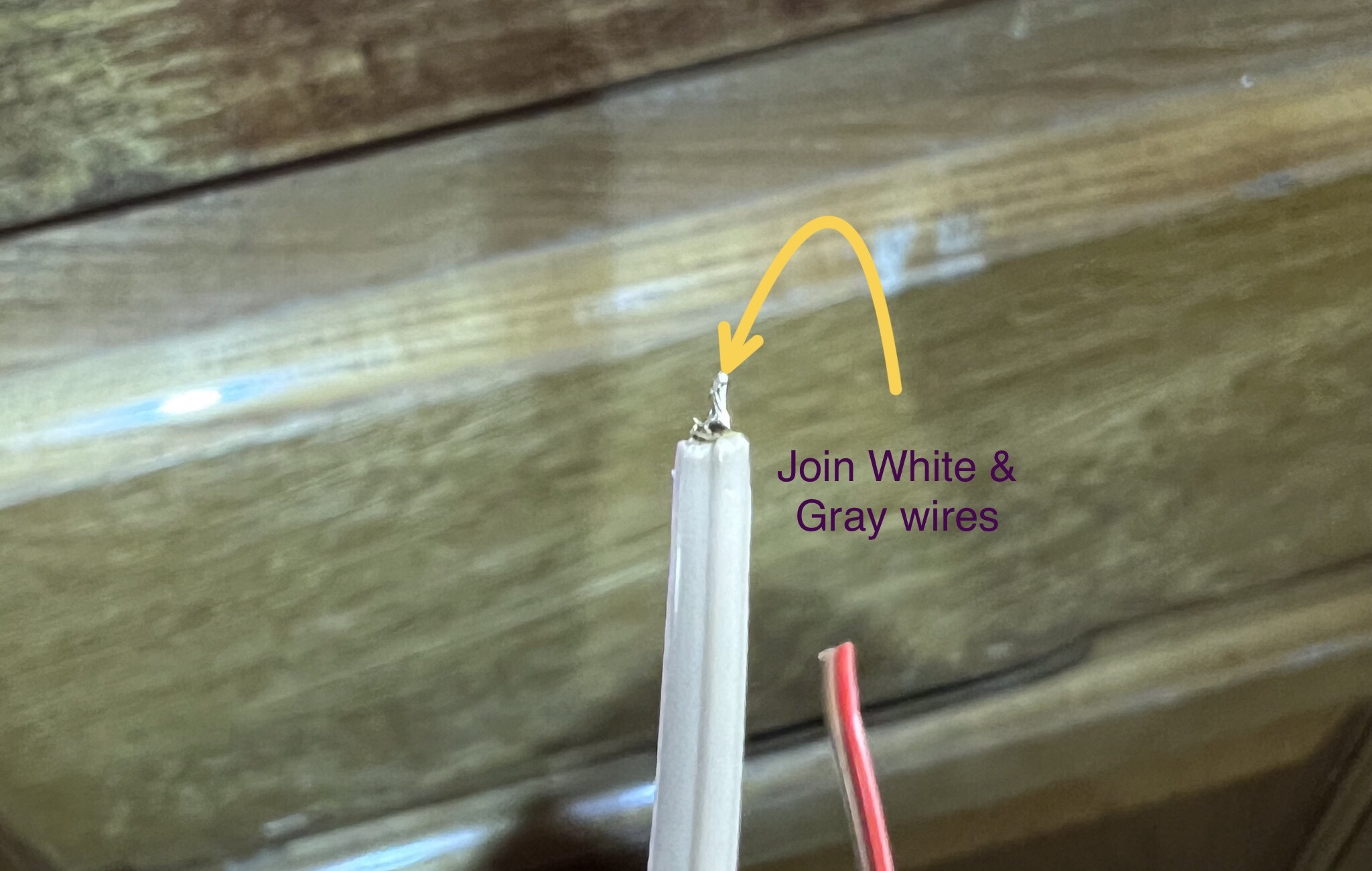
Solder wires 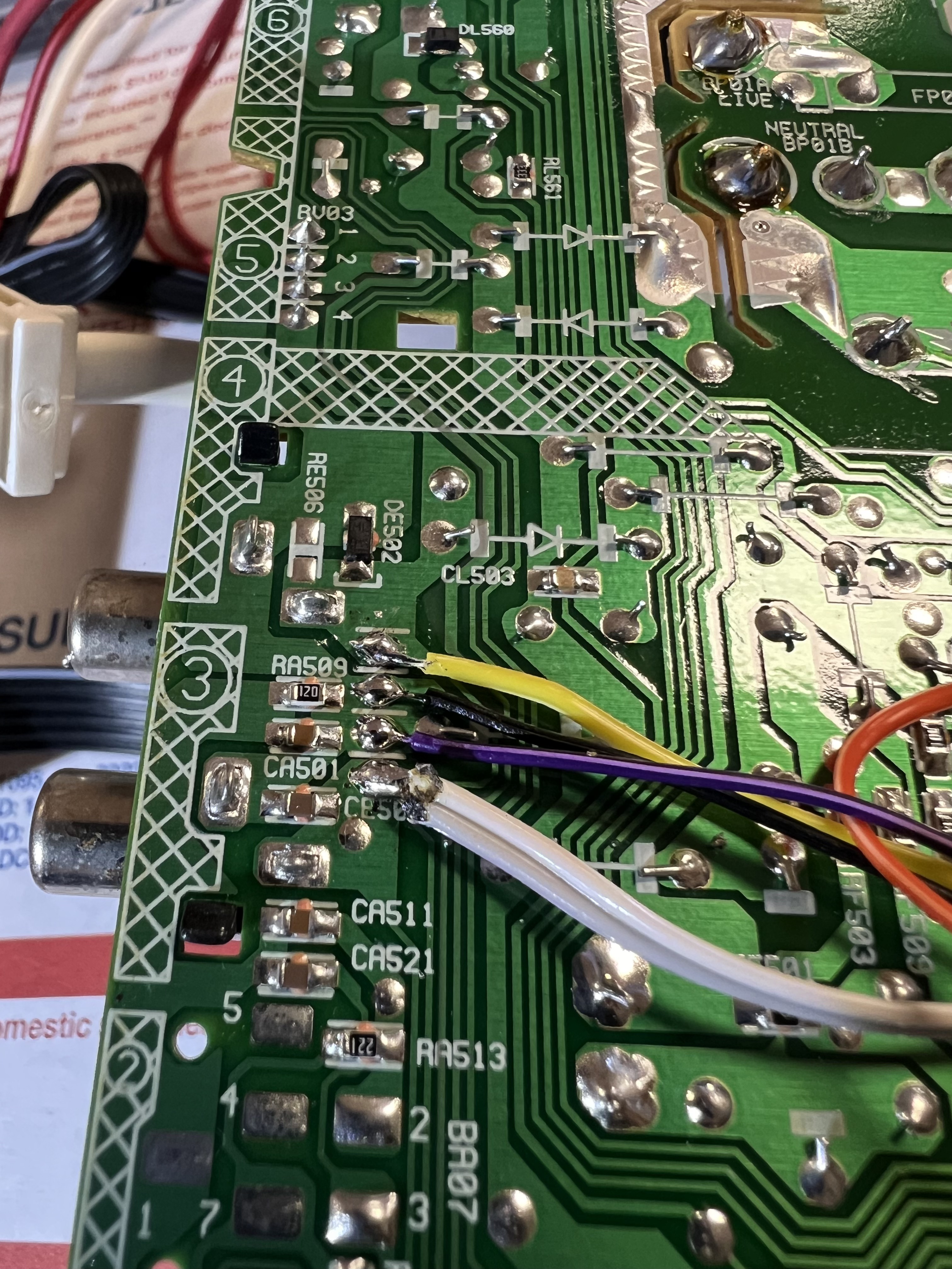
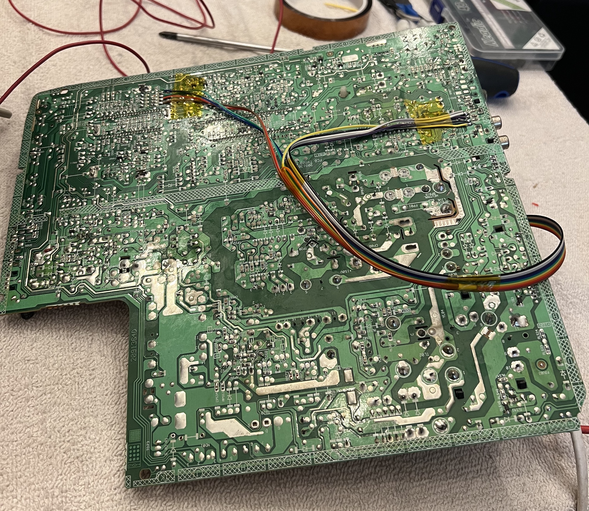
Full board after the mod
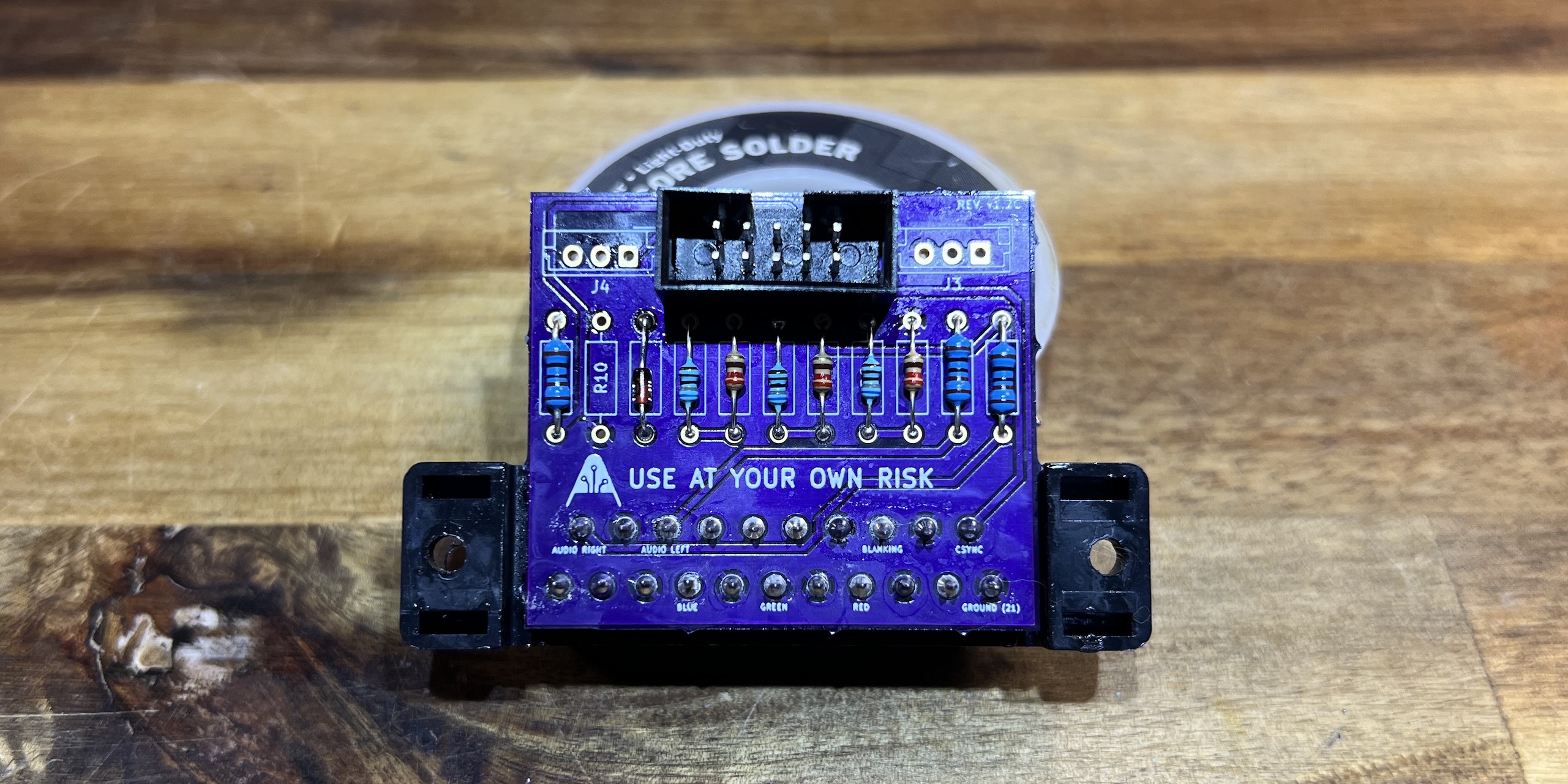
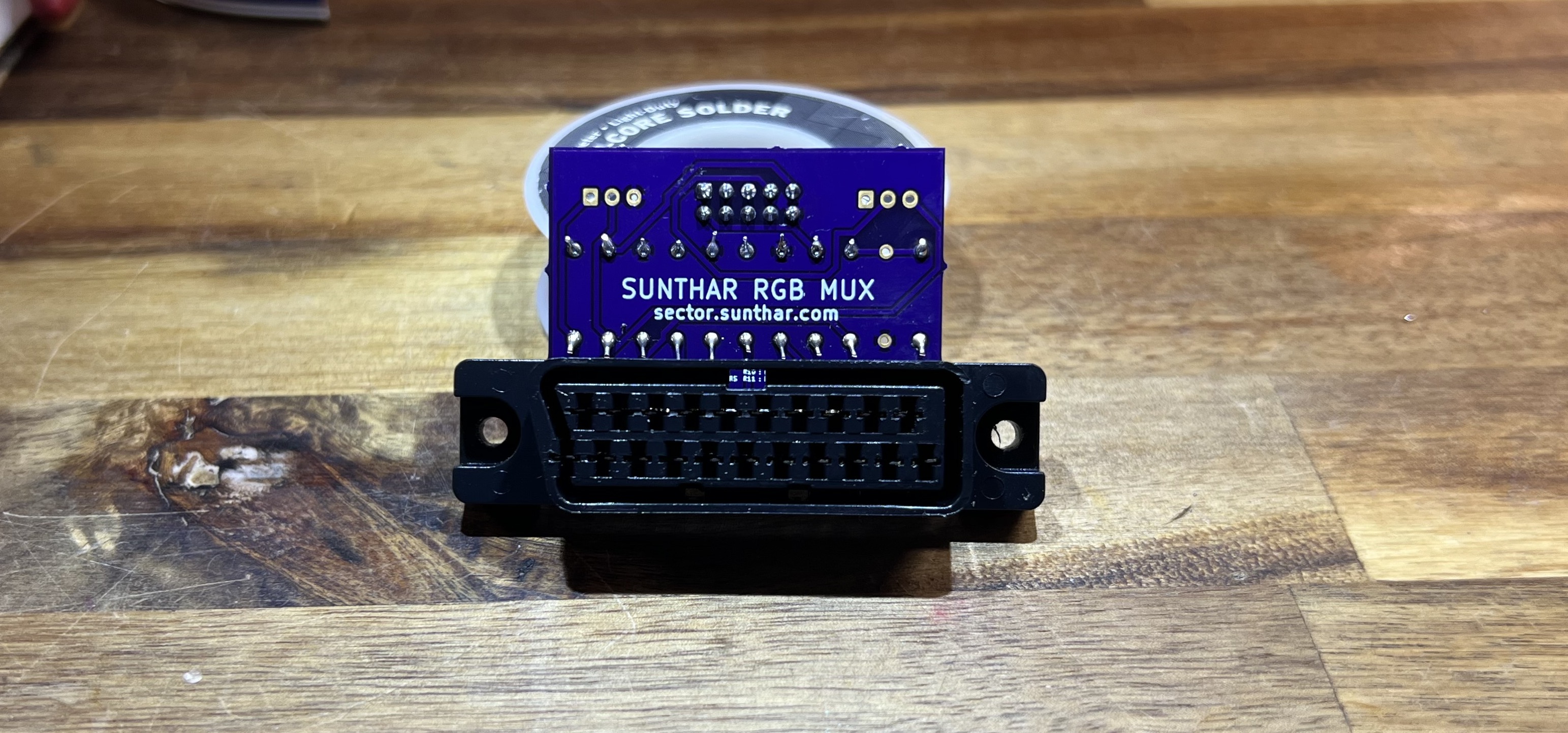
STEP 5: Build your mux board/circuit
This mod uses the RGB mux board. This is optional, but will make your mod easier and stable. You can also create the circuit presented in the schematics above without the board. Please also checkout the mux calculator to play with your own values.
| Component | Value |
|---|---|
| RGB/OSD inline resistor (chassis) | 3.3kΩ |
| Removed RGB/OSD resistor (chassis) | 820Ω |
| RGB inline diode method (chassis) | Yes |
| RGB termination (R1, R2, R3) | 180Ω |
| RGB inline (R4, R5, R6) | 820Ω |
| Audio LR (R7, R8) | 1kΩ |
| Diode (R9) | 1N4148 |
| Blanking Ground Resistor (R10) | open |
| Blanking Resistor (R11) | 1.2kΩ |
Compatible mux boards:
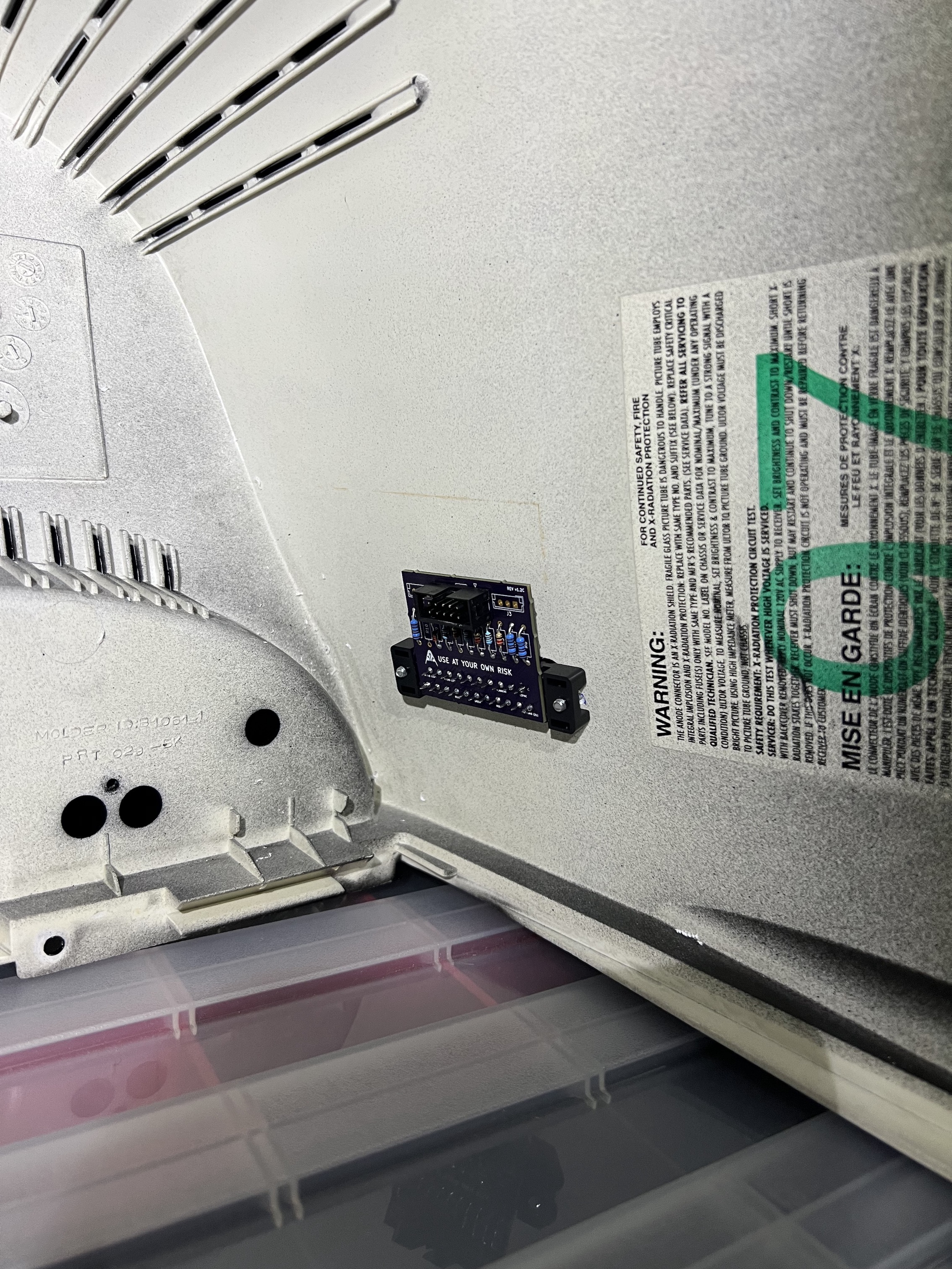
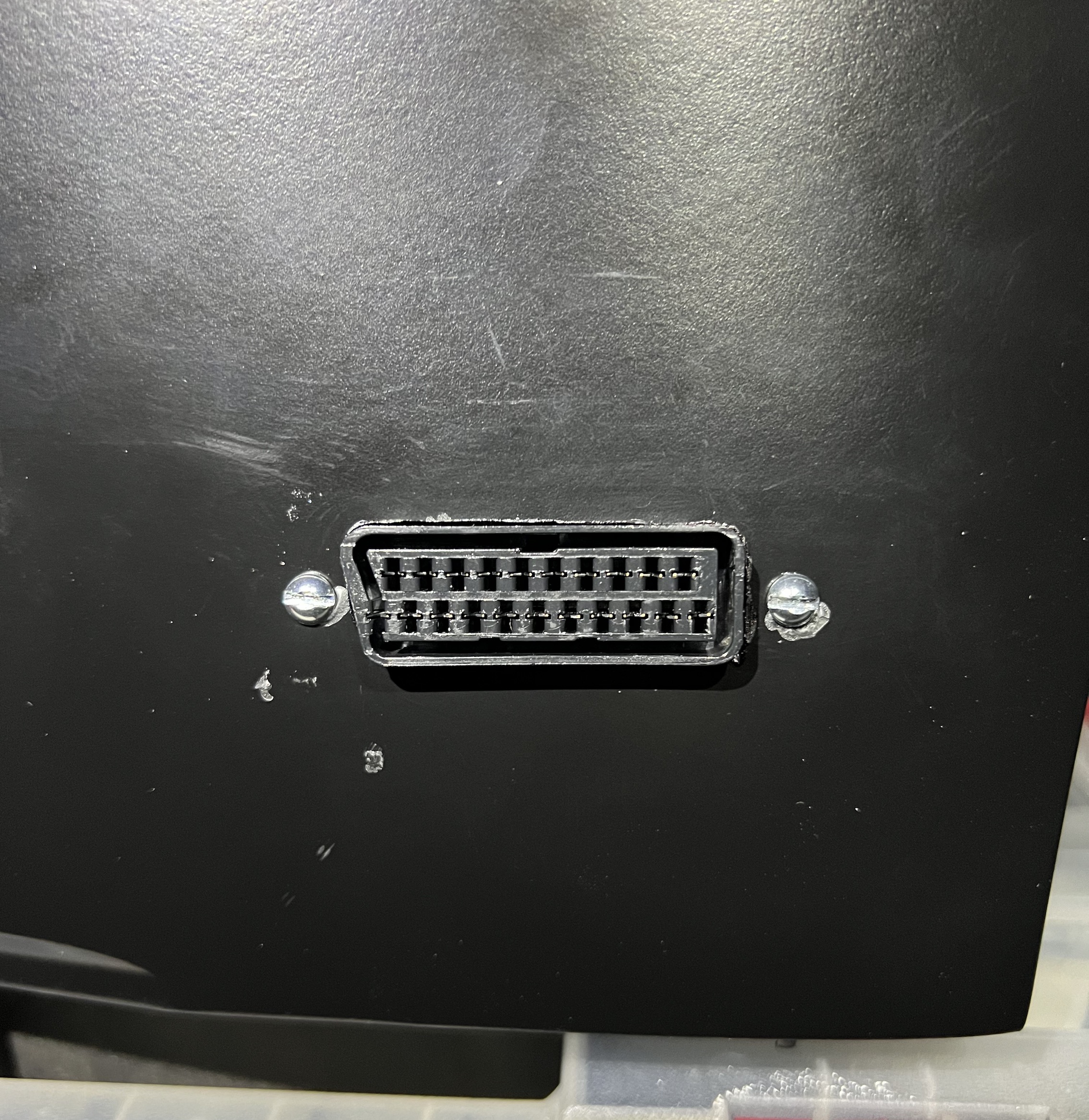
STEP 6: Attach the female SCART connector to TV
Creating a SCART cutout and mounting it is an art. I have a dedicated section for it.
How to create and mount a SCART female plug?
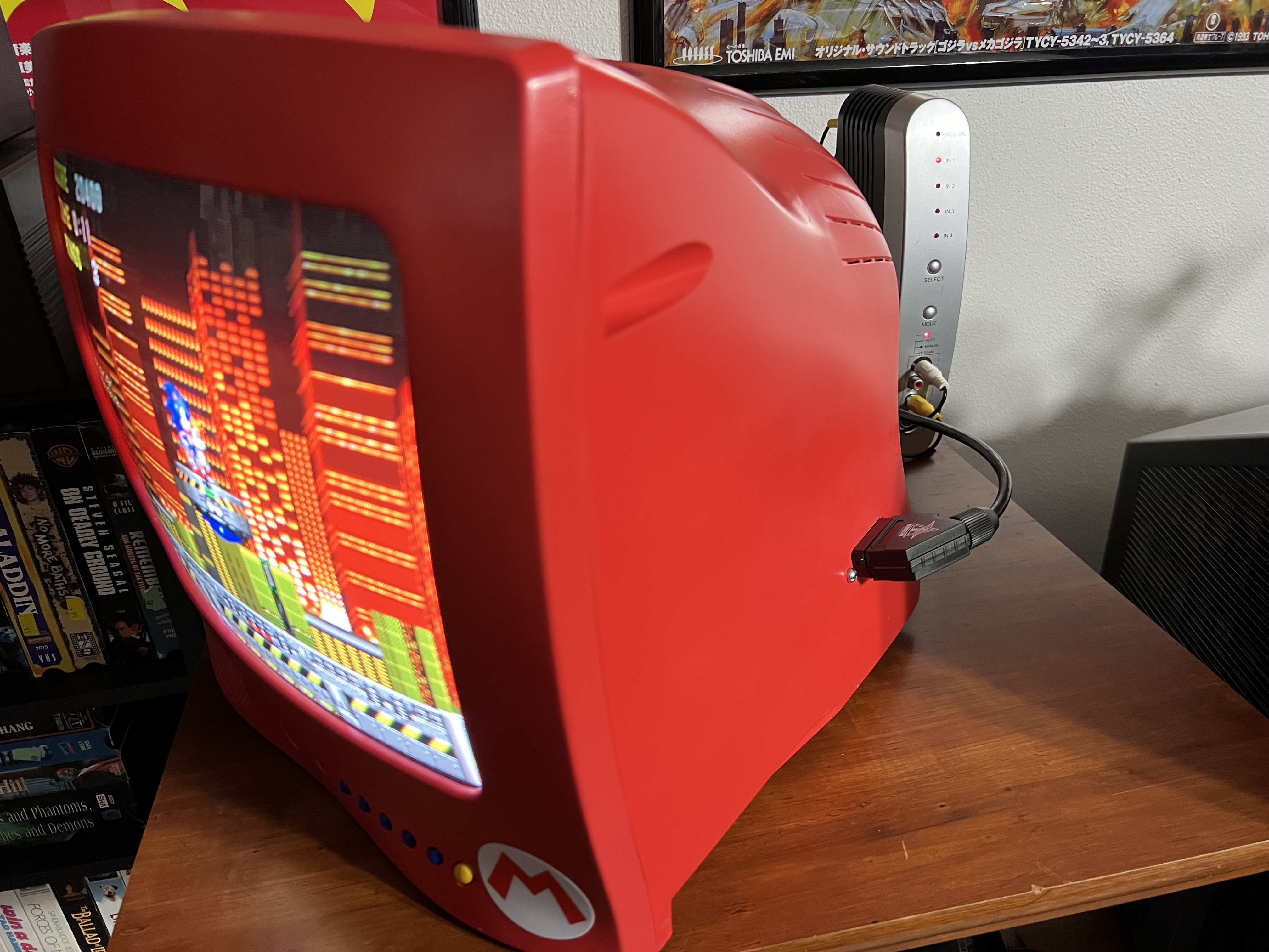
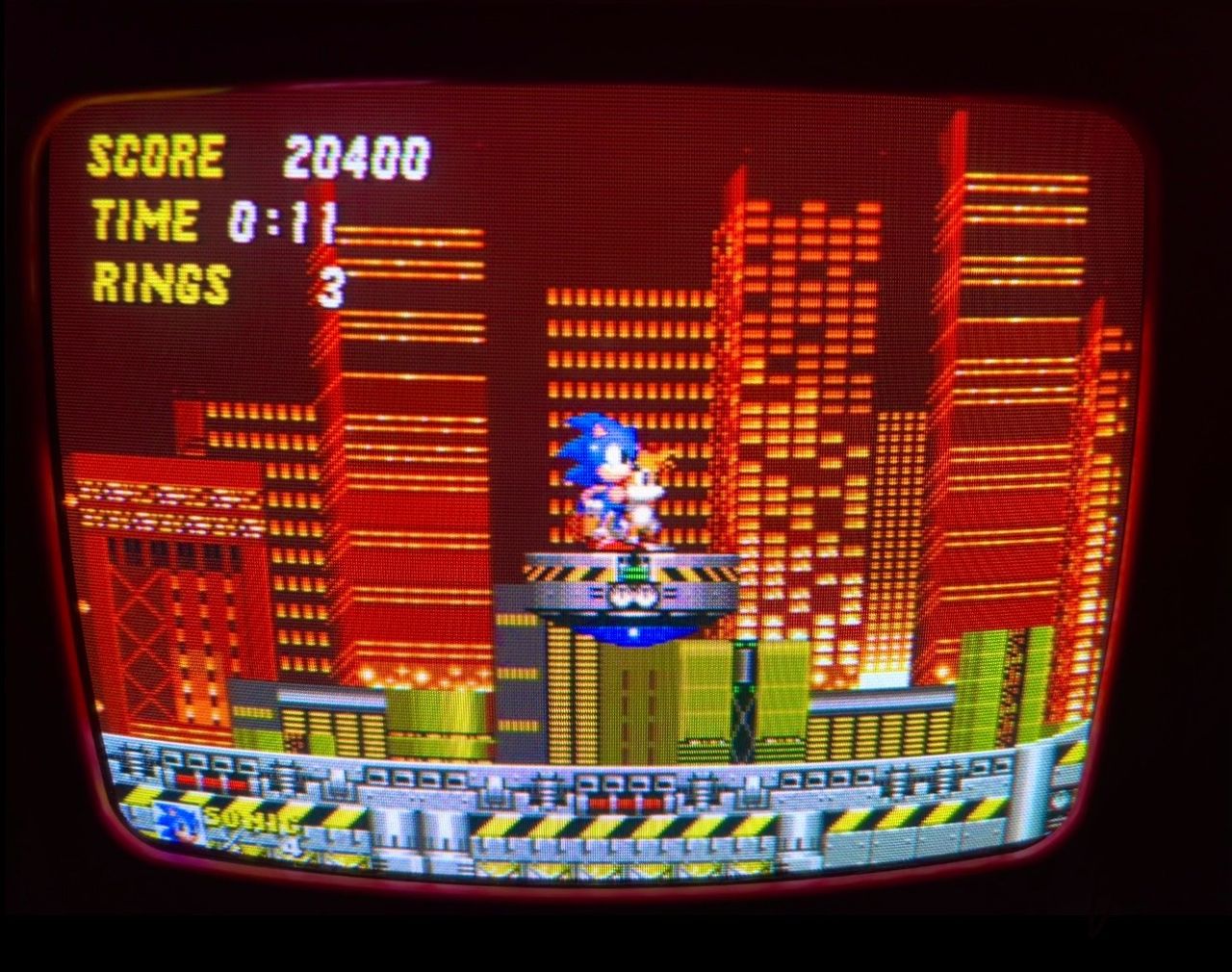
Pictures
Reference Photos