Sanyo DS27214
Sanyo DS27214 CRT RGB mod
Is it possible to transform a CRT found on the curb into the ultimate retro gaming machine? Let's find out.
This tutorial covers the RGB mod for Sanyo DS27530. These instructions should also work for the below CRTs.
- Sanyo DS27214
- Sanyo DS27530
- Sanyo DS31520
- Sanyo DS27800
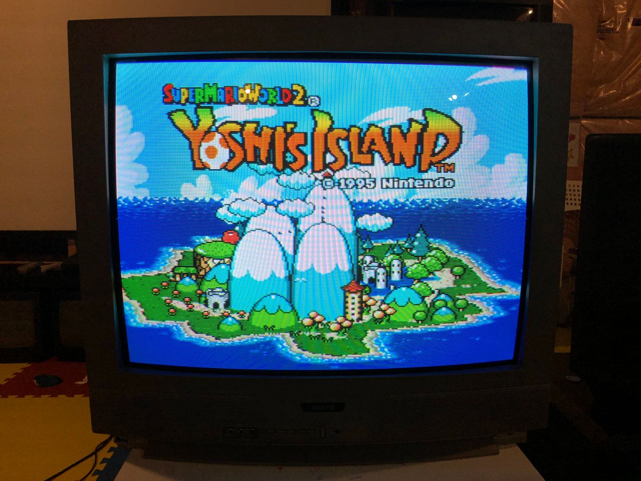
The Sanyo DS27214 is a 27" CRT television that delivers a super sharp, colorful image with excellent geometry.
View full CRT details and more mod examples →
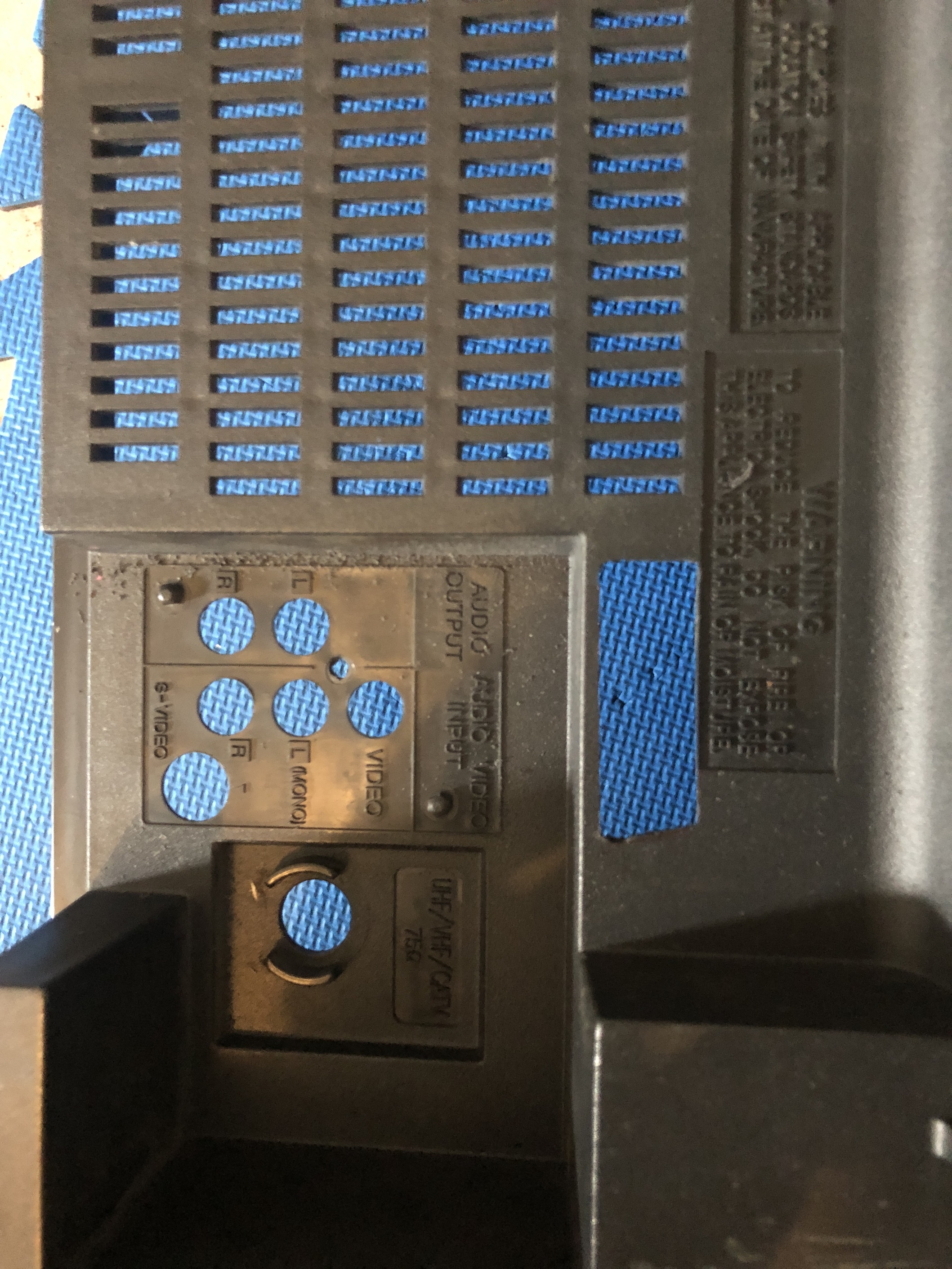
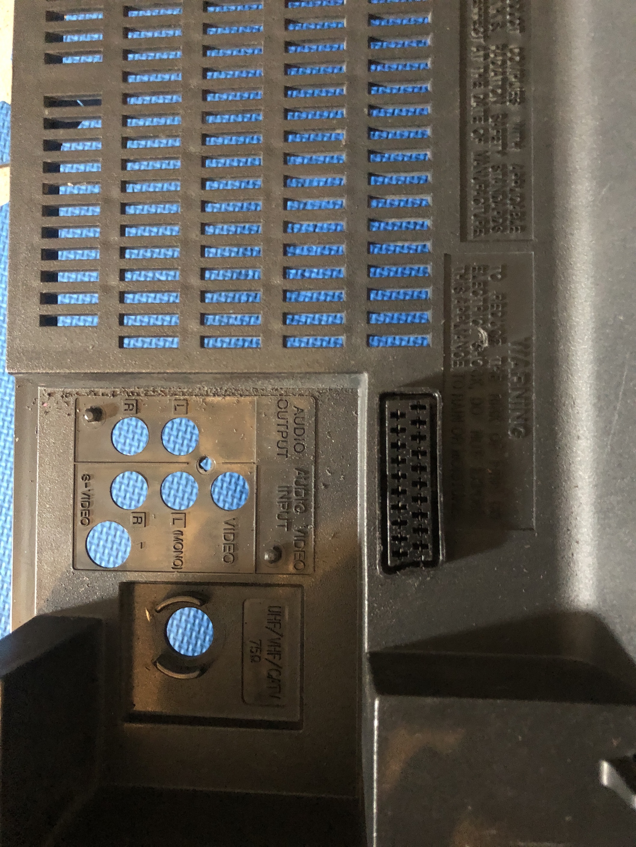
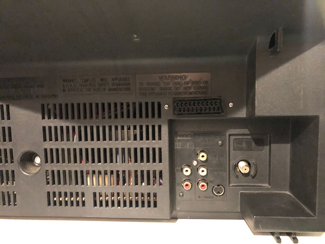
Given that this CRT TV solely features one composite input at the front, one composite input, one s-video input, and an RF input at the back, it's certainly worthwhile to modify it for RGB input. Although a few adjustments are required, the modification process employs the standard mux mod.
I discovered this CRT lying next to a community donation bin, where electronics are not permitted to be dumped. Moreover, it was carelessly left on its side in the mud. Despite some minor damage to the plastic lip of the front casing, it was fortunate that the rest of the device remained unscathed. I believe that this CRT was exposed to the rain for a minimum of two days. After contemplating for about 5 minutes, due to the mud on the back, I eventually decided to seize the opportunity and take it with me for some experimentation. Looking back, I'm glad I made that choice.
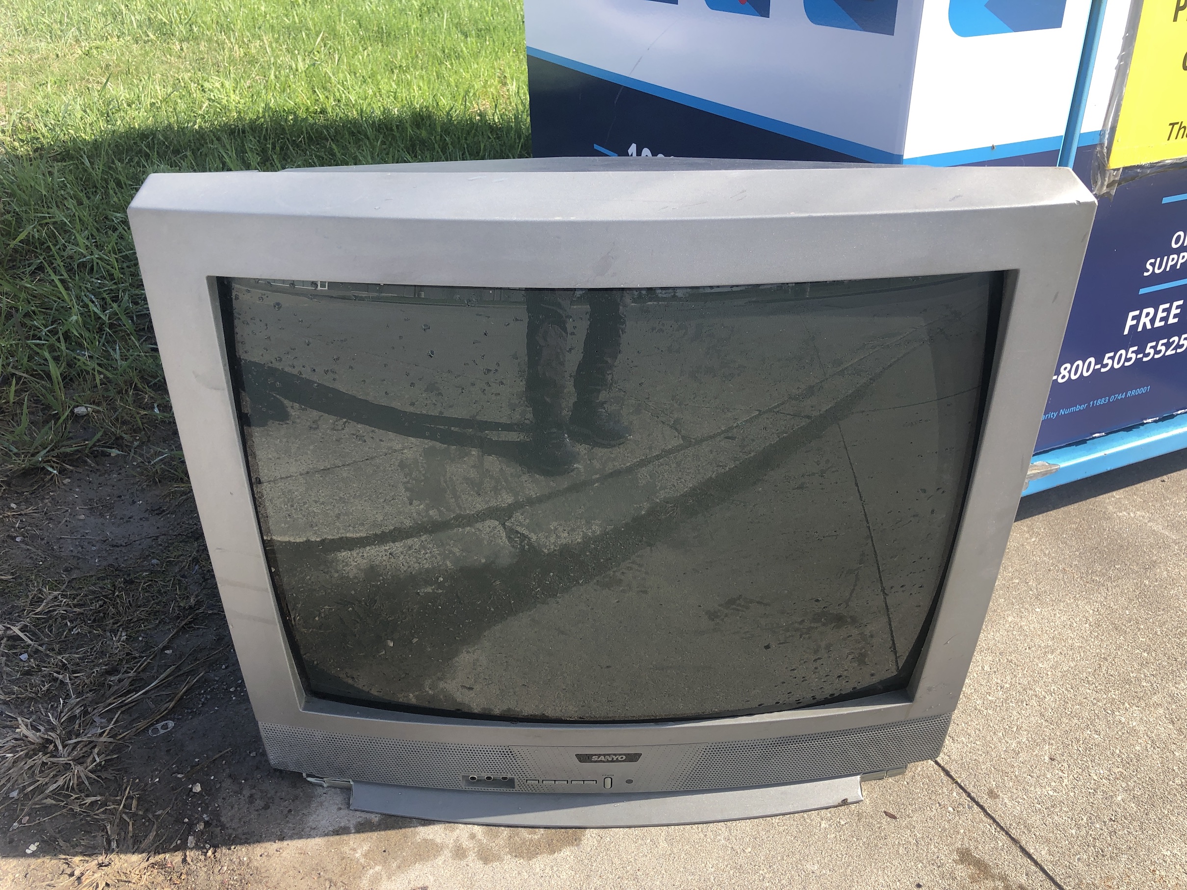
It's regrettable that this set was abandoned in such a condition. The tube utilized in this set is the same as the ones found in JVC D-Series, and the chassis is quite robust with several advanced protection features. Most importantly, it's capable of being modified for RGB input!!!
Contributors
Thank you to everyone who contributed to this guide:
- Sunthar — contributor, RGB mod and pictures
CRT safety
Caution
You can die doing this! So read carefully! CRT TV is not a toy. Do not open a CRT TV. If you don't have any prior knowledge about handling high voltage devices, this guide is not for you. CRT TV contains high enough voltage (20,000+ V) and current to be deadly, even when it is turned off.
Plan of attack
Manuals and Datasheets
Specs
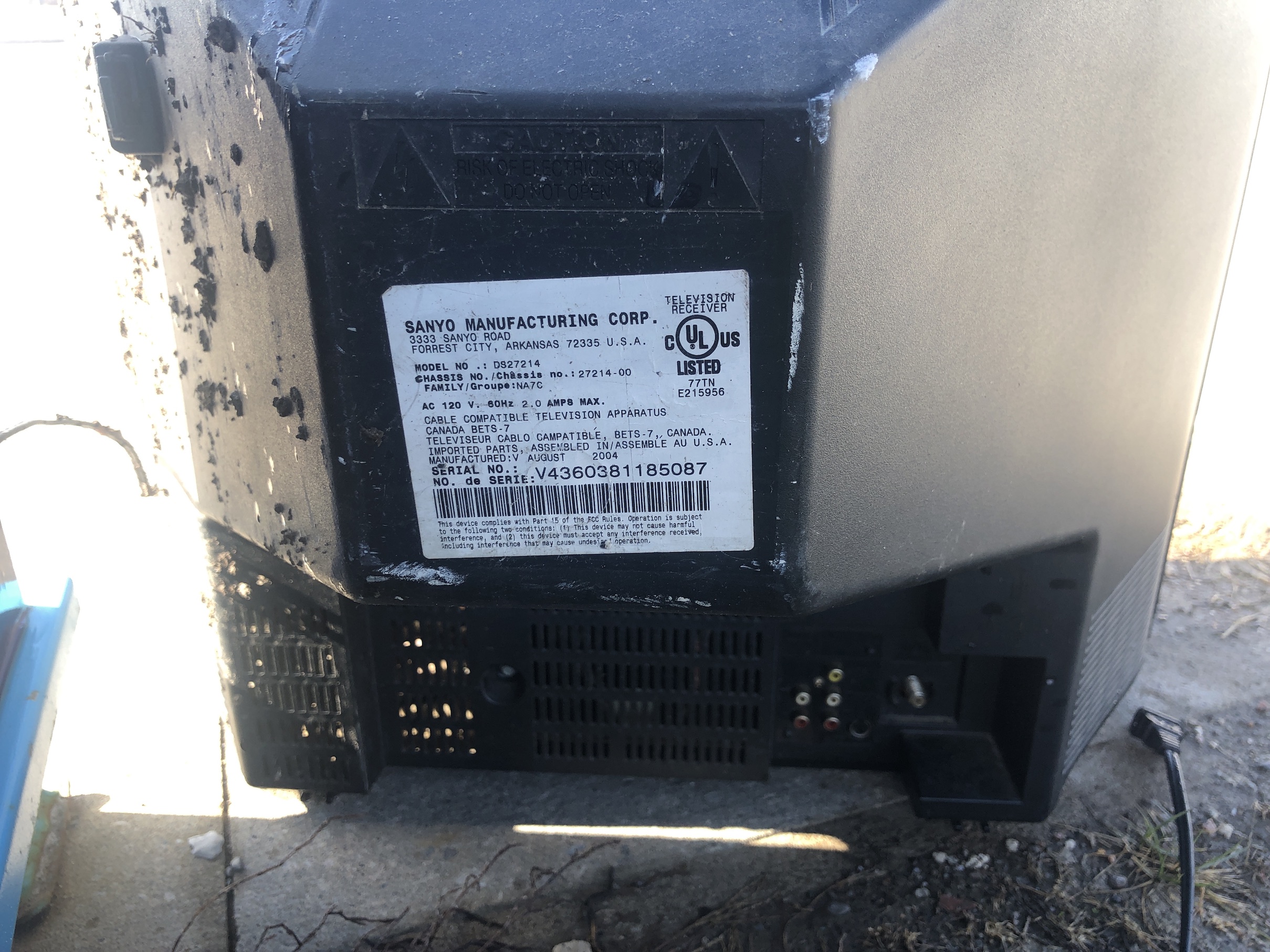
- Manufactured: USA ()
- Chassis: DS27214-00
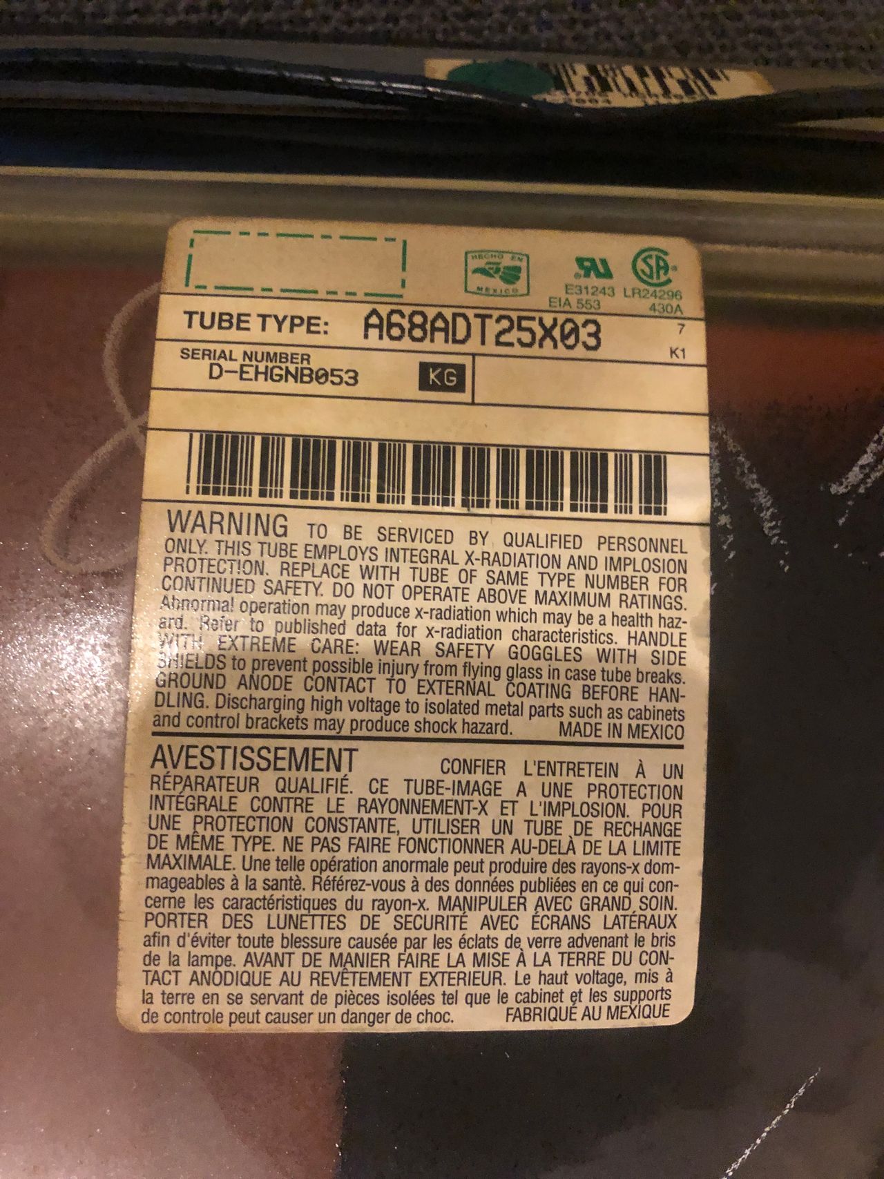
- Tube: RCA A68ADT25X03
- Jungle Chip: Sanyo LA76834NMP
- OSD Chip: QXXAVB927P
- Screen Size: 27"
Schematics
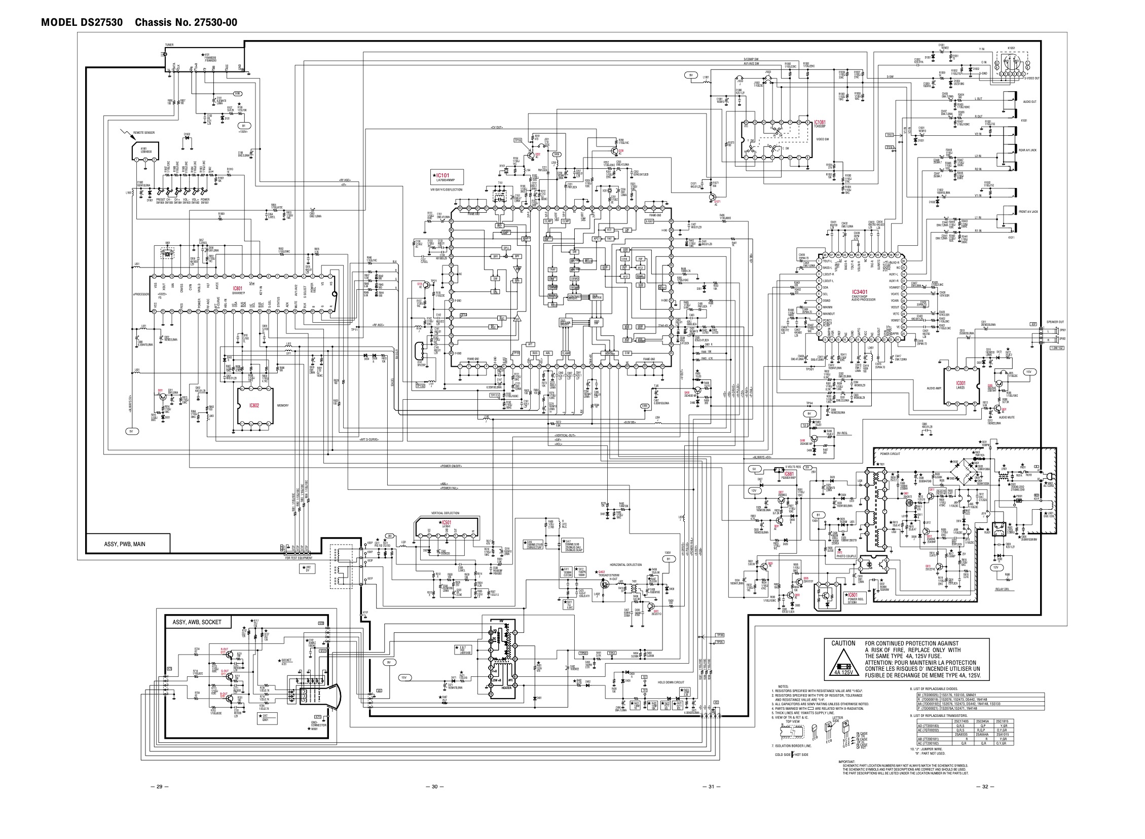
Zoomed in 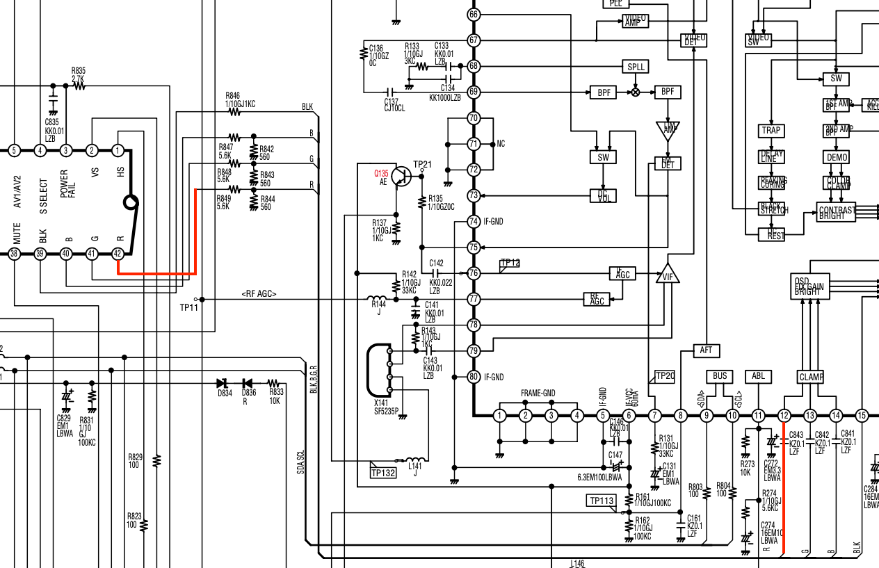
RGB mux diagram
Prepare the mux diagram. If you are building your own circuit, this diagram should help.
Calculating the RGB external resistor value
Let's put theories to some practical use. Formula from our theory page!
We find out using ohms law, this CRT is using 0.5Vp-p. But, how?
Vp-p = 5V x (560/(5600+560)) = 5V x 0.0909 = 0.45V

RGB external resistor value
= (0.5 x (5600 + 75) - (75 x 5)) / (5 - 0.5)
= (0.5 x 5675 - 375) / 4.5
= 2462 / 4.5
= 550Ω
560Ω resistors should do the job.
Performing the mod
Now that you roughly know what needs to be done, prepare for the mod. Place the board on a comfortable place. Make sure you are not putting pressure on the flyback or other components.
STEP 1: Remove the following components
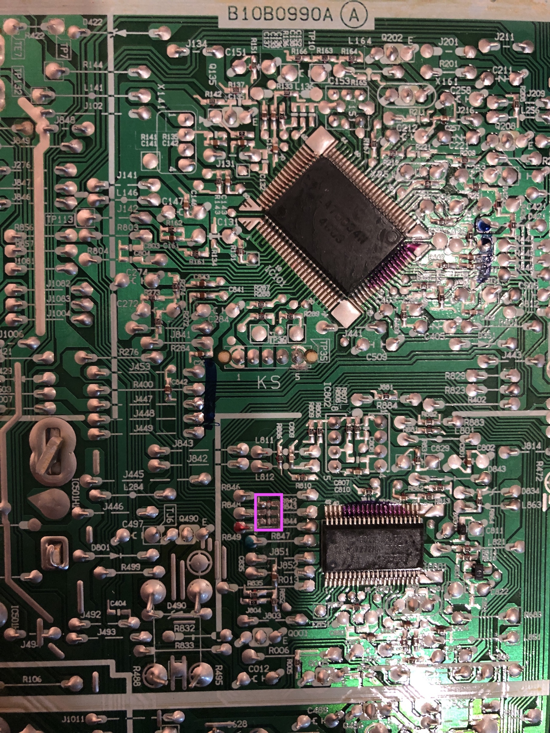
Remove the following components. RGB resistors to the ground. Measure twice and mark before you remove.
- R842 (560Ω)
- R843 (560Ω)
- R844 (560Ω)
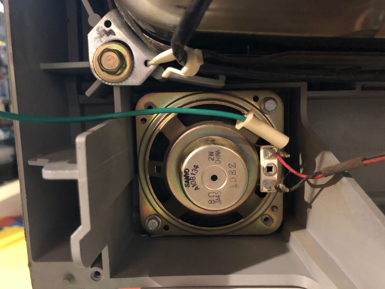
STEP 2: Connect RGB, Blanking
Refer to the picture below to connect the RGB and blanking wires. Be sure to solder them to the leg of the resistor that is facing away from the OSD chip.
![]()
STEP 3: Blanking diode
To prevent current from flowing back into the OSD and causing interferences in RGB mods, it's necessary to include a diode in the blanking line. The absence of this diode is the main cause of such issues. ![]()
STEP 4: Sync and Audio
Sync and Audio can be connected to Video 2 input. You can also connect sync to the S-Video luma input to reduce the RGB shift. 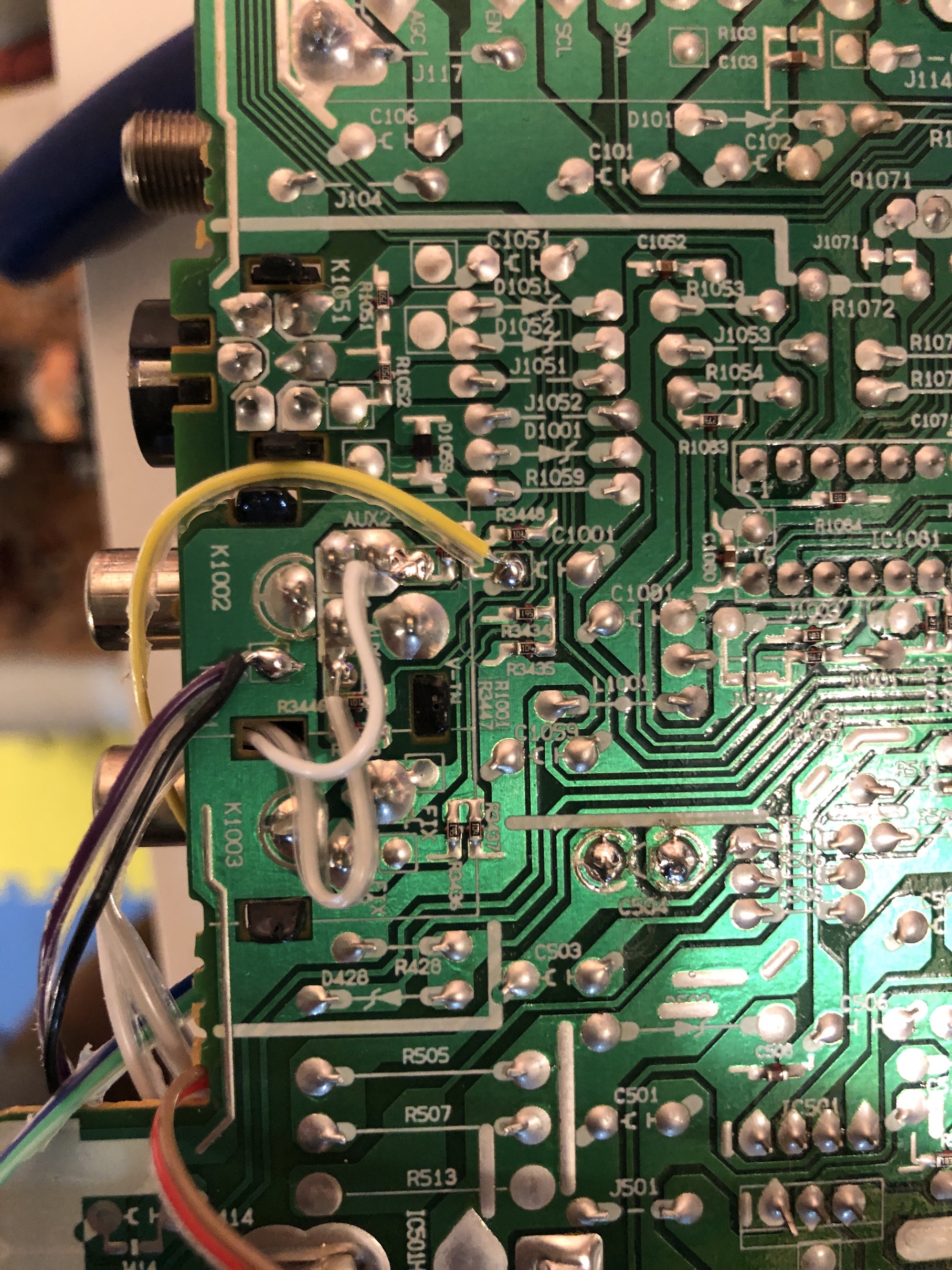
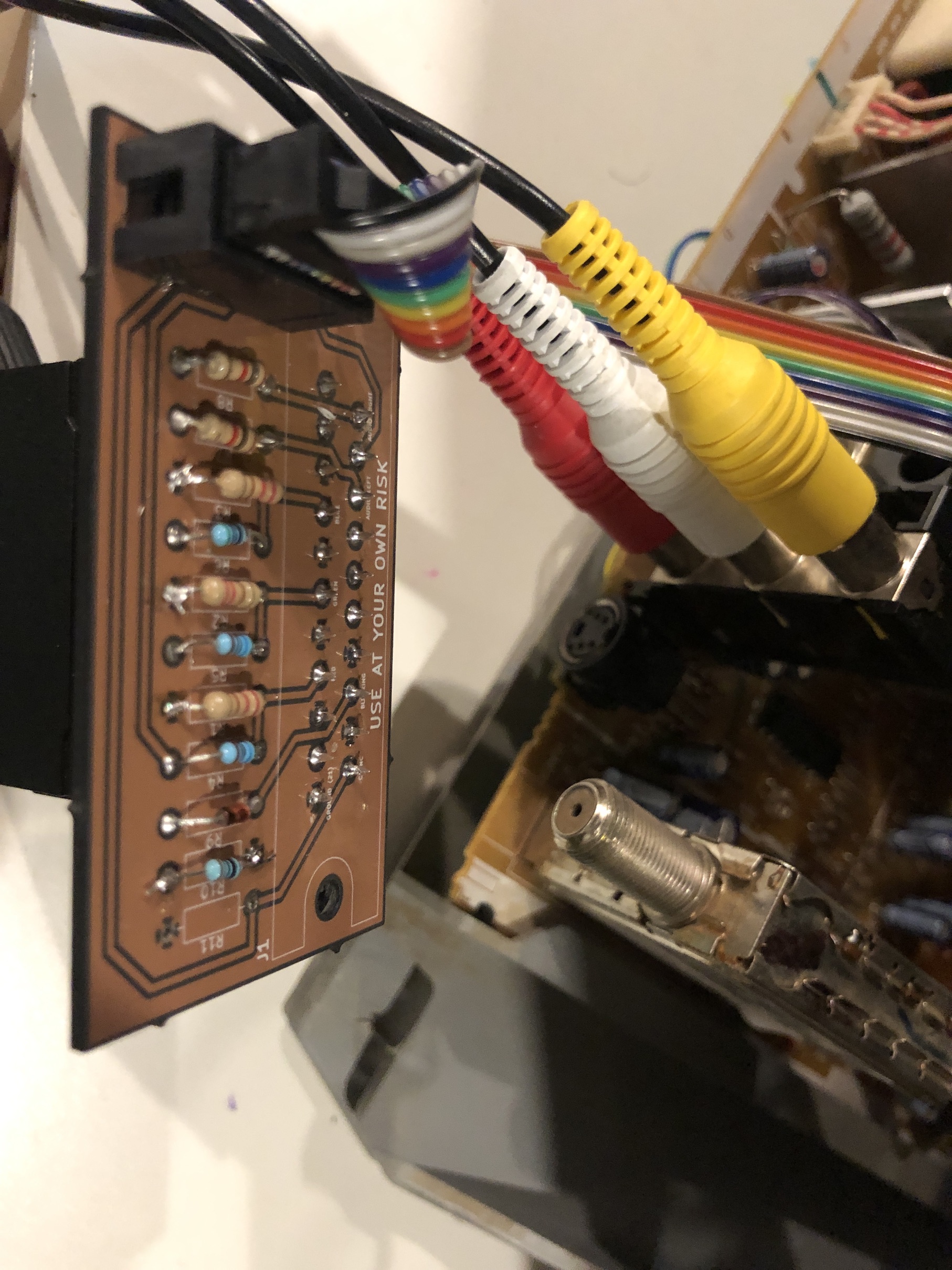
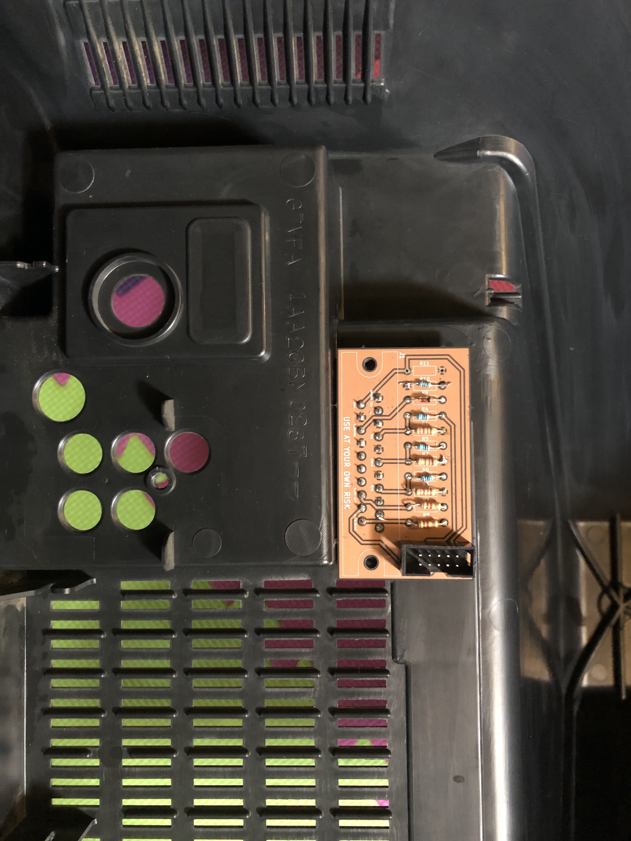
STEP 5: Build your mux board
This mod uses the RGB mux board. This is optional, but will make your mod easier and stable. You can also create the circuit presented in the schematics above without the board. Please also checkout the mux calculator to play with your own values.
| On Sanyo CRT Chassis | DS27214 |
|---|---|
| CRT RGB inline resistor | 5.6kΩ |
| CRT RGB ground resistors removed | 560Ω |
| 0.1μF caps replaced | No |
| Add RGB diodes on chassis | No |
| Add blanking diode on chassis | Yes |
| RGB mux board | DS27214 |
|---|---|
| Mux board RGB termination (R1, R2, R3) | 220Ω |
| Mux board RGB inline resistors (R4, R5, R6) | 560Ω |
| Mux board Audio LR (R7, R8) | 1kΩ |
| Mux board blanking diode (R9) | 1N4148 |
| Mux board blanking ground resistor (R10) | open |
| Mux board blanking resistor (R11) | 1kΩ |
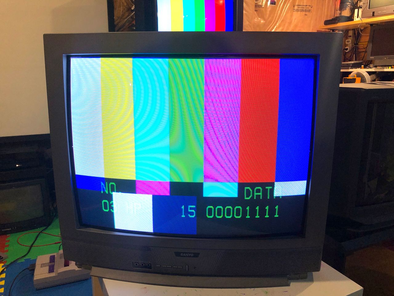
STEP 6: Service Menu and User Menu Adjustments
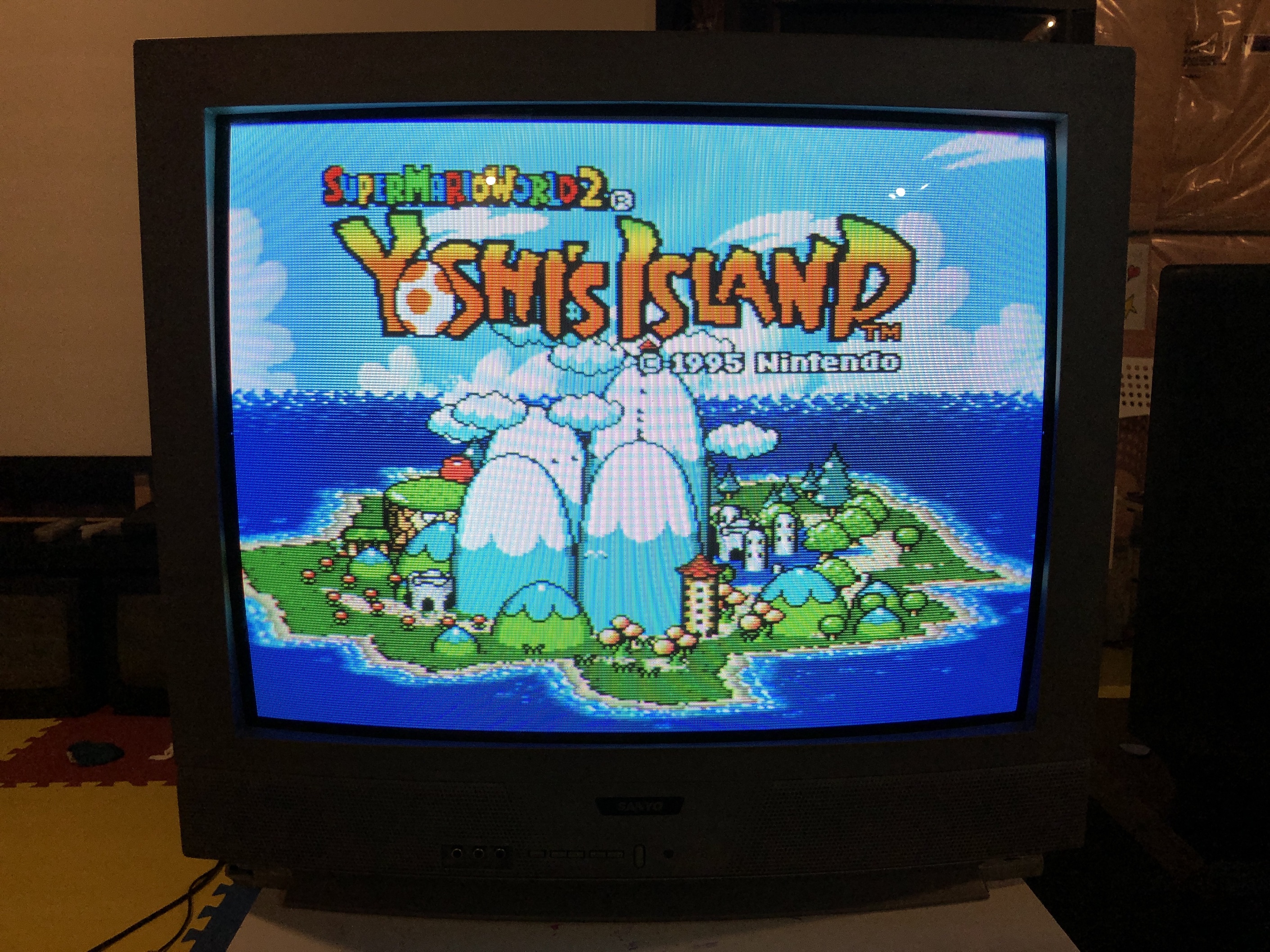
To attain the appropriate equilibrium between composite/s-video input and RGB input, numerous adjustments to both the Service Menu and User Menu were required for this set. Once set, you don't have adjust these when you switch inputs.
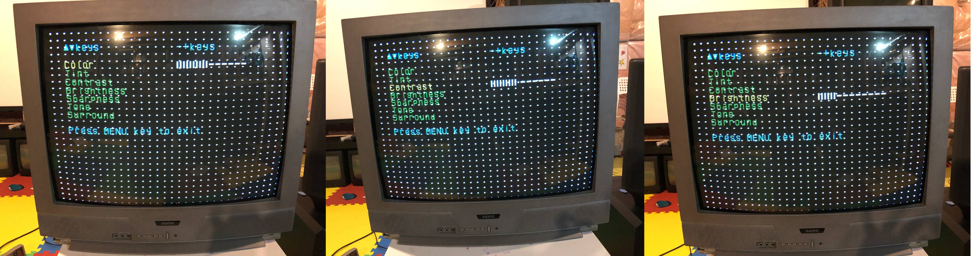
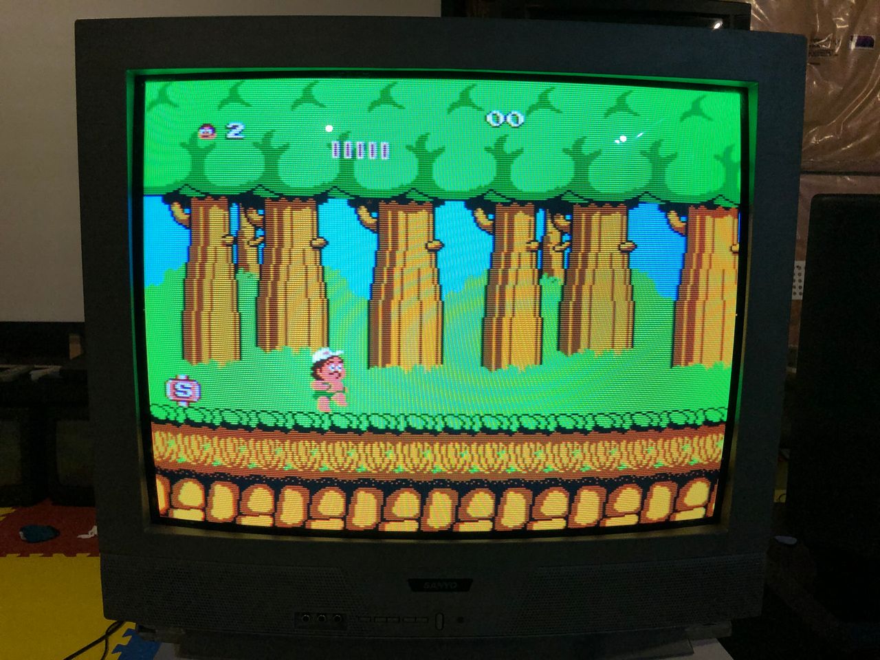
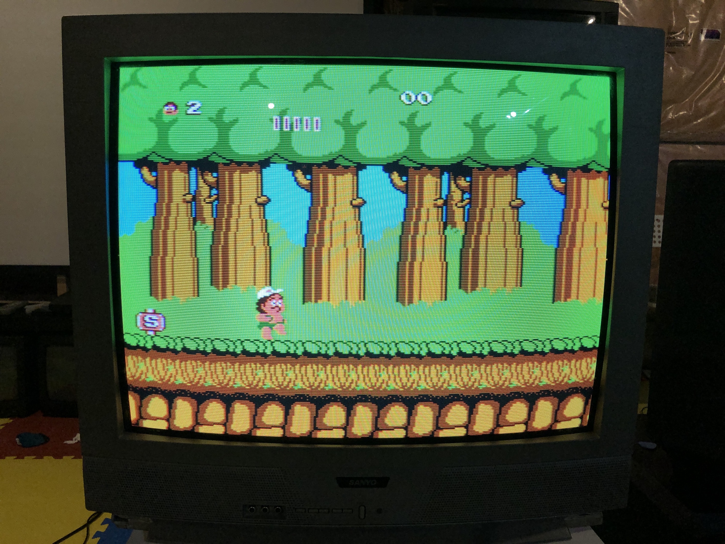
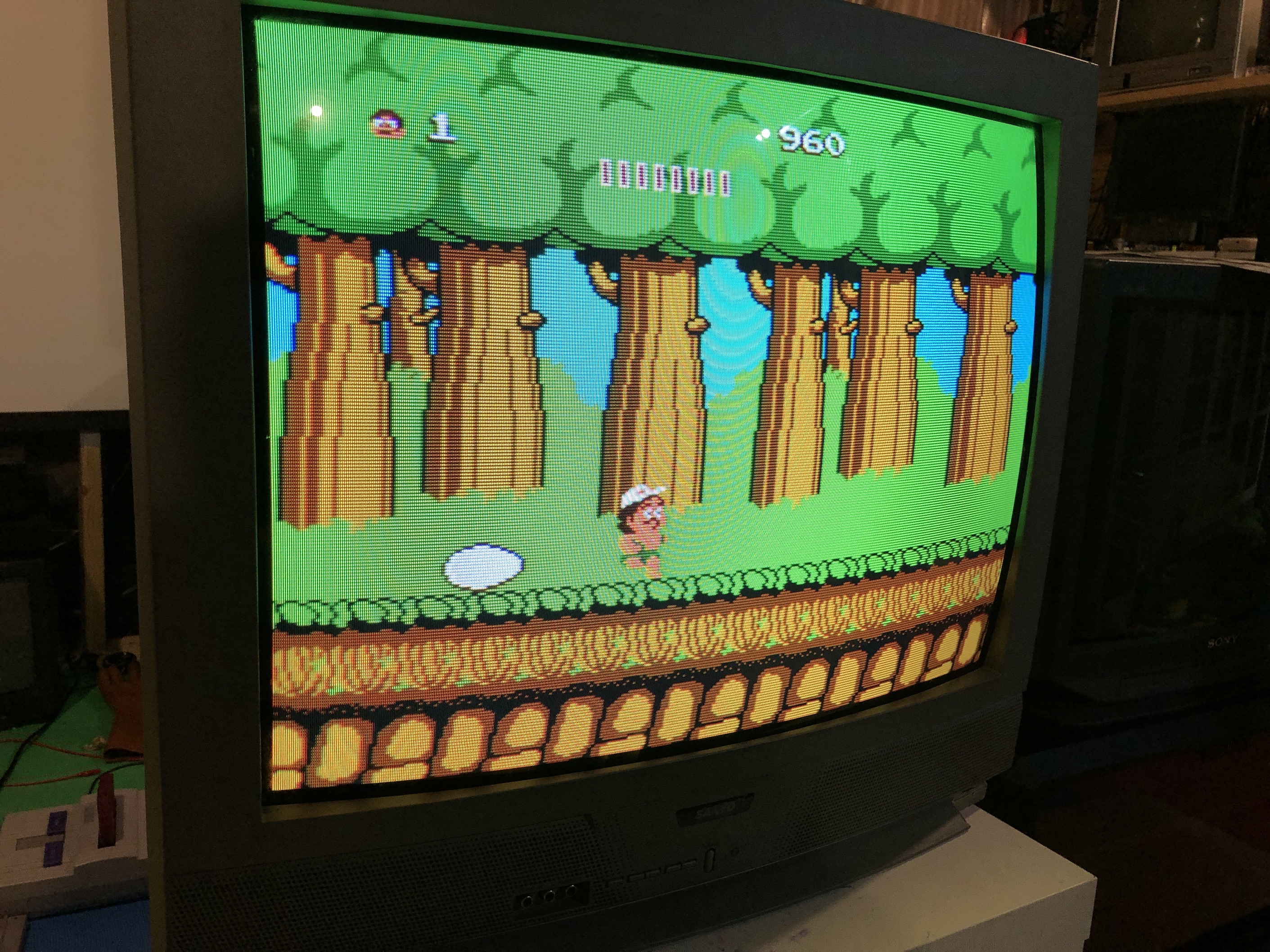
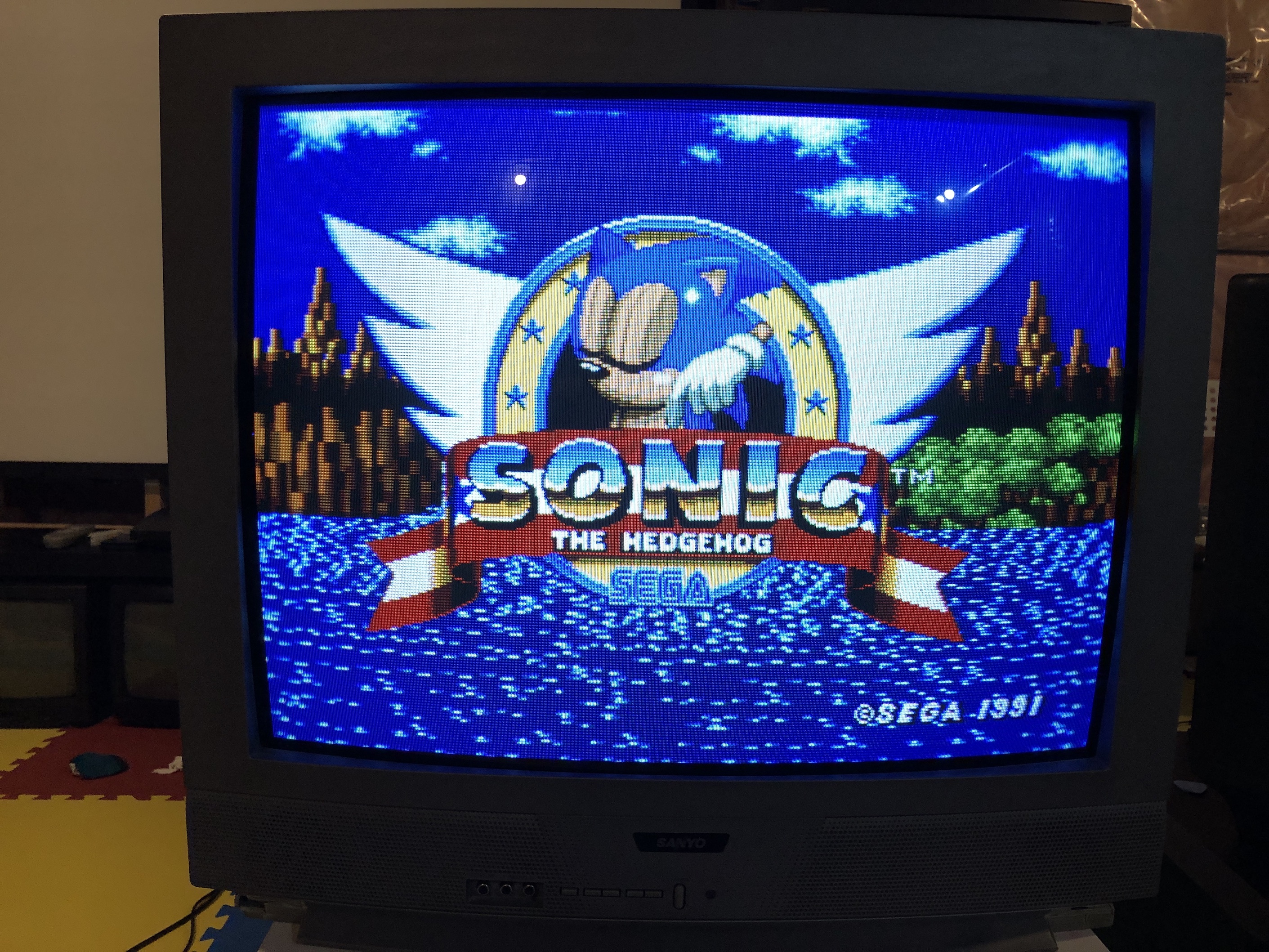
The above image also demostrates that RGB/OSD mux is working!
How to get into the Service Menu
While pressing the MENU key on the front of the TV, reconnect the AC power cord. The Service Menu Display will now appear.
I have only highlighted the values I changed here. You can scroll down to see the full service menu settings details
| NO. | TITLE | SANYO | ADJUSTED | RANGE OF DATA | FUNCTION |
|---|---|---|---|---|---|
| 3 | HP | 11 | 15 | 0~31 | Horizontal Centering |
| 4 | VS | 66 | 69 | 0~127 | Vertical Size |
| 15 | RB | 12 | 200 | 0~255 | Red Bias |
| 16 | GB | 0 | 180 | 0~255 | Green Bias |
| 17 | BB | 2 | 179 | 0~255 | Blue Bias |
| 18 | RD | 75 | 55 | 0~127 | Red Drive |
| 19 | GD | 11 | 6 | 0~15 | Green Drive |
| 20 | BD | 73 | 59 | 0~127 | Blue Drive |
| 21 | SBI | 48 | 55 | 0~127 | Sub Bias |
| 22 | OSD | 3 | 1 | 0~3 | OSD Contrast |
| 37 | AF | 1 | 0 | 0, 1 | Auto Flesh |
| 53 | SB | 24 | 0 | 0~63 | Sub Bright |
| 54 | SCO | 14 | 14 | 0~31 | Sub Color |
| 55 | STI | 24 | 20 | 0~31 | Sub Tint |
STEP 7: Attach the female SCART connector to TV
Creating a SCART cutout and mounting it is an art. I have a dedicated section for it.
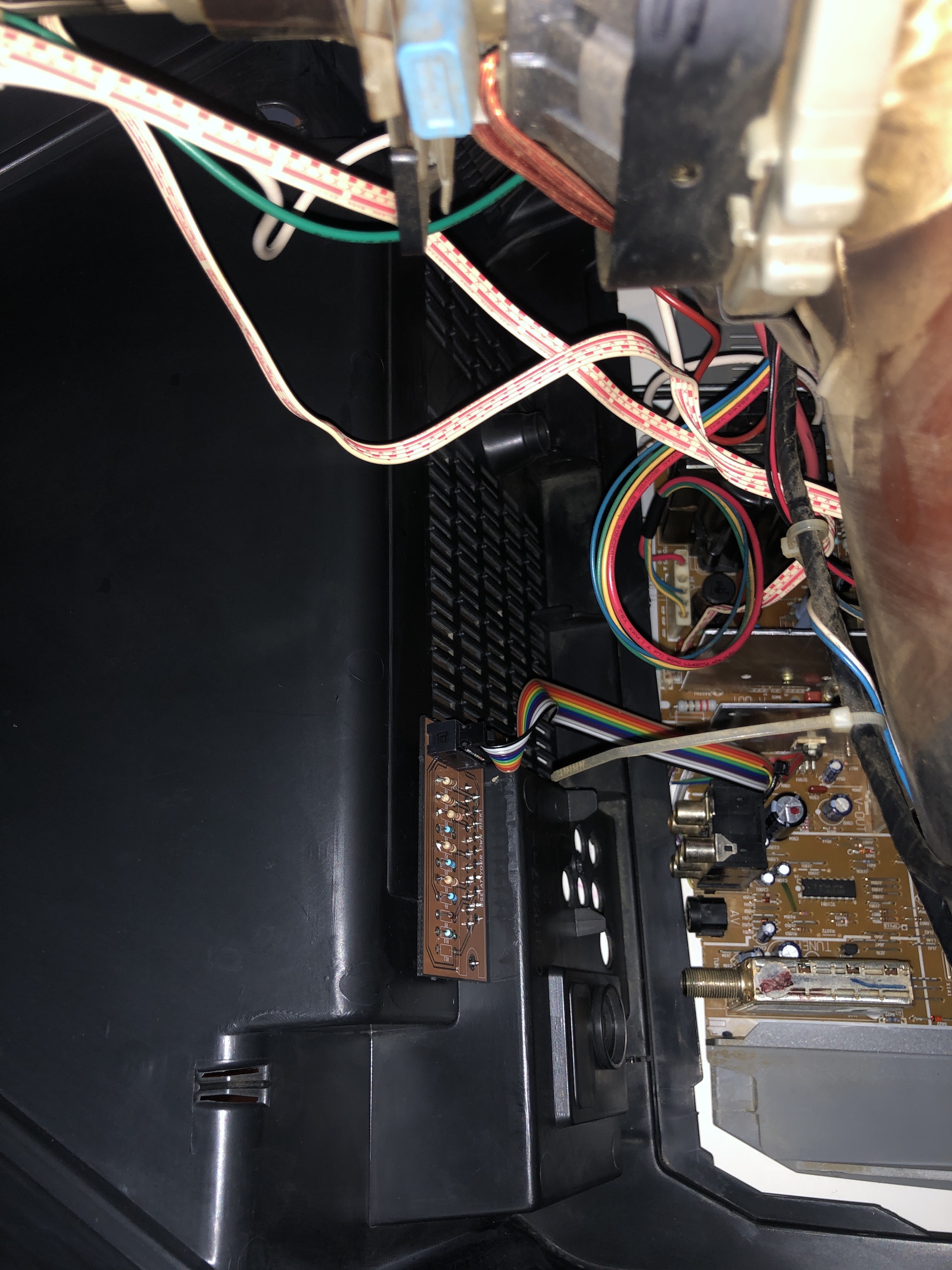
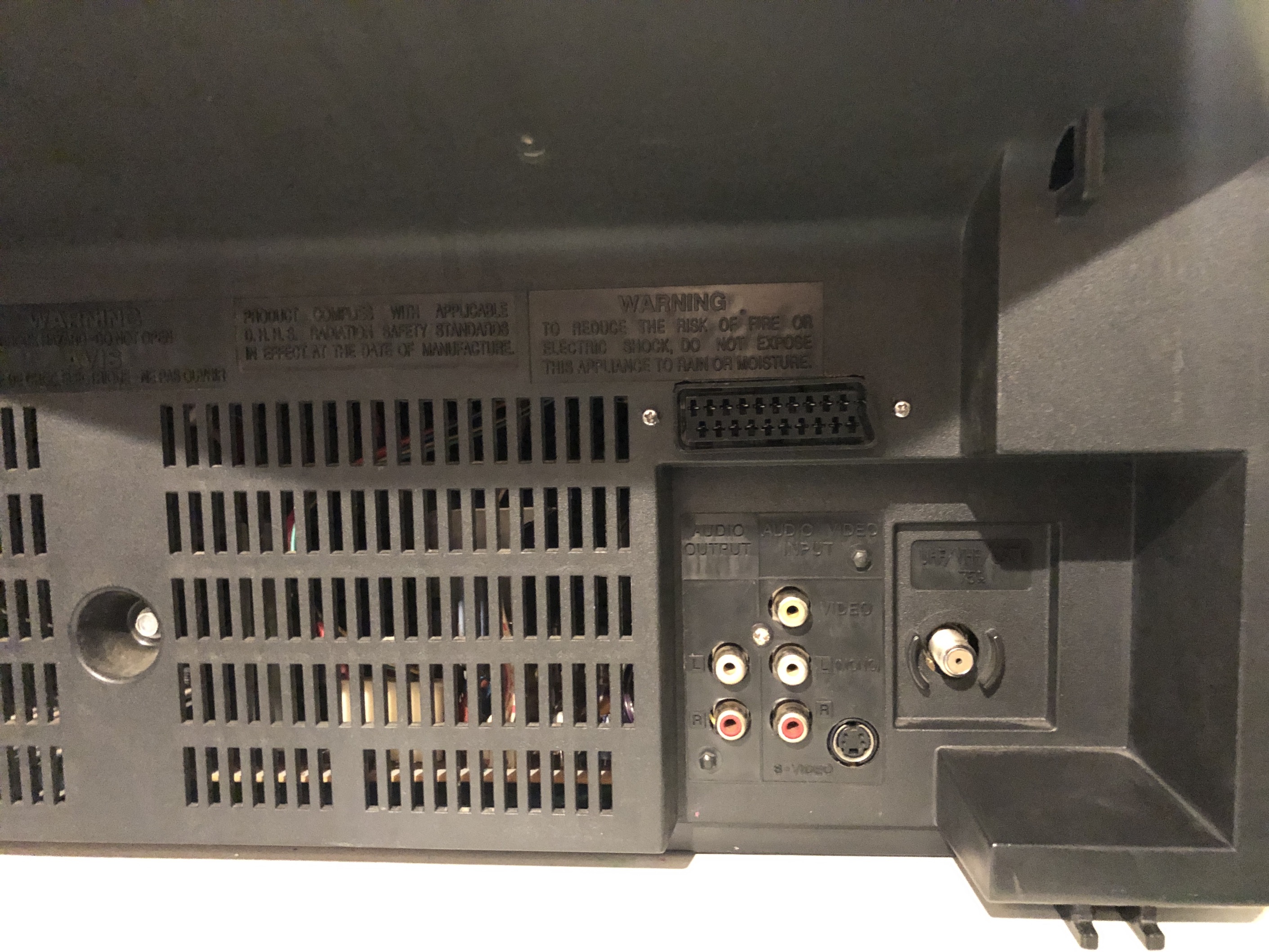
How to create and mount a SCART female plug?
Remote Control for this TV
Despite not having the remote control for this CRT, I was able to use a universal Sony RM-AV3000 remote control with the code 8025 successfully.
The end
Found a home for this CRT 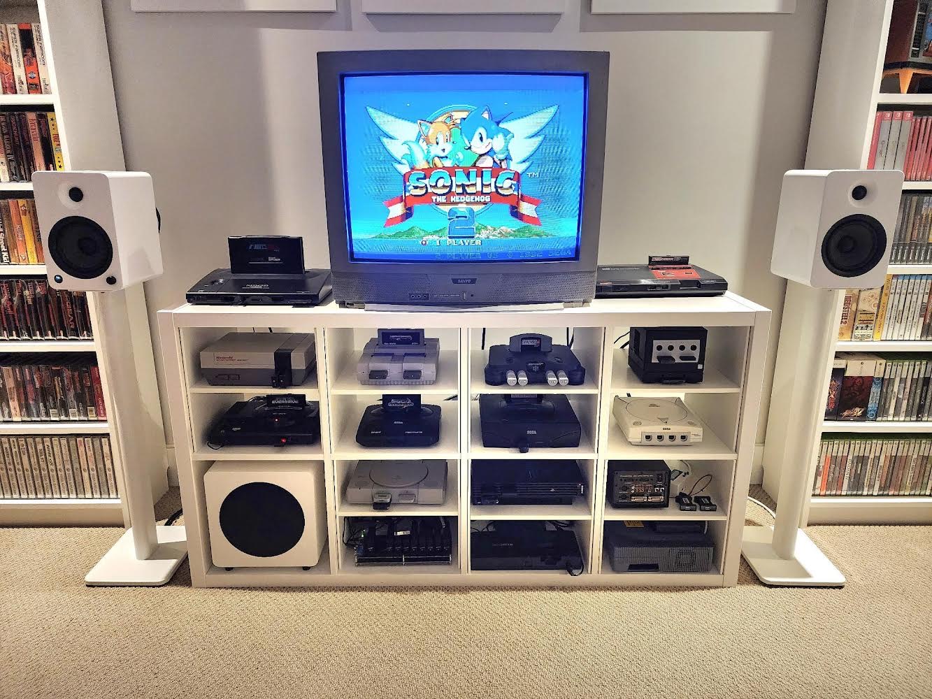
Pictures
Reference Photos


See more photos and contributions →
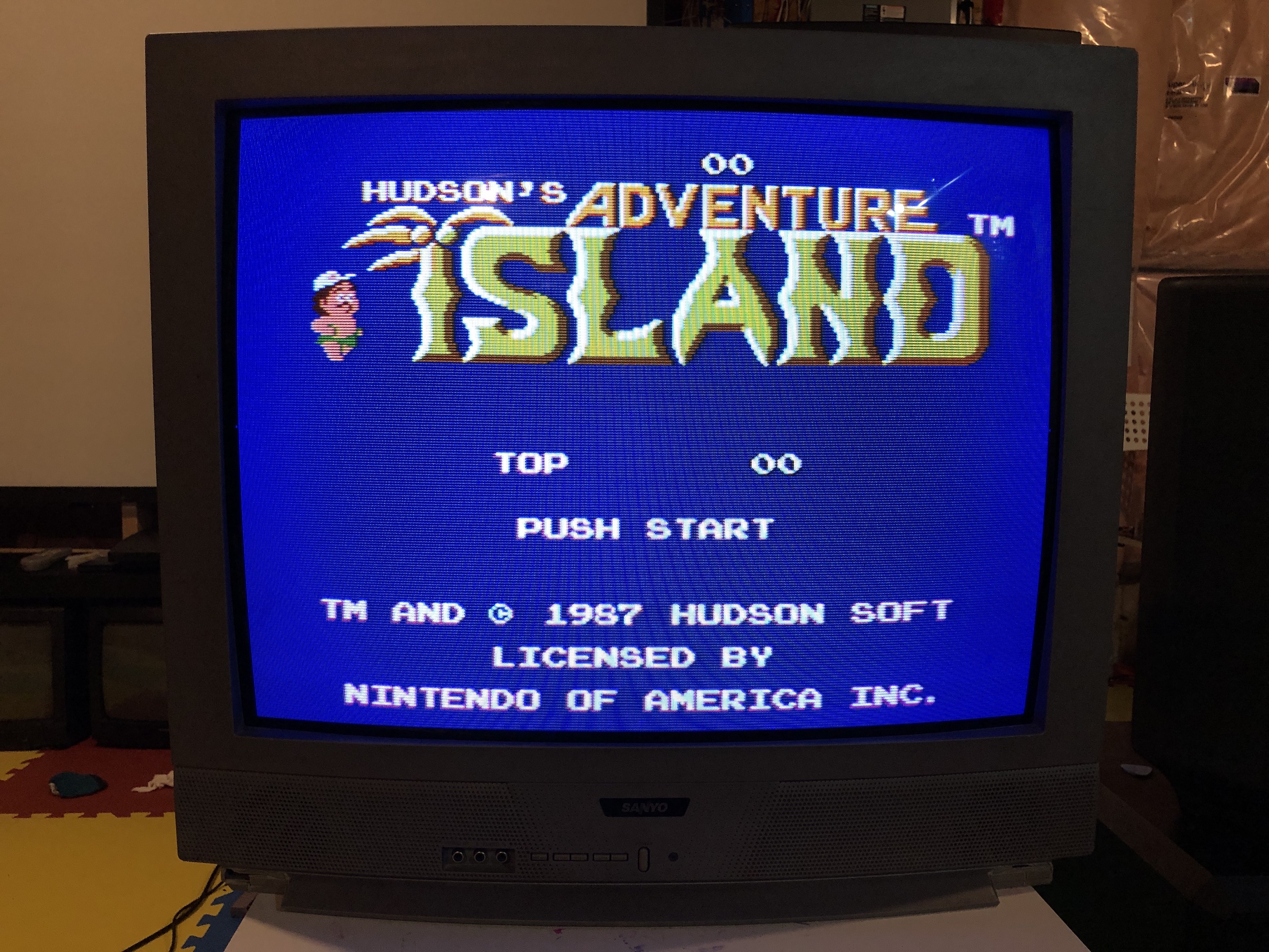
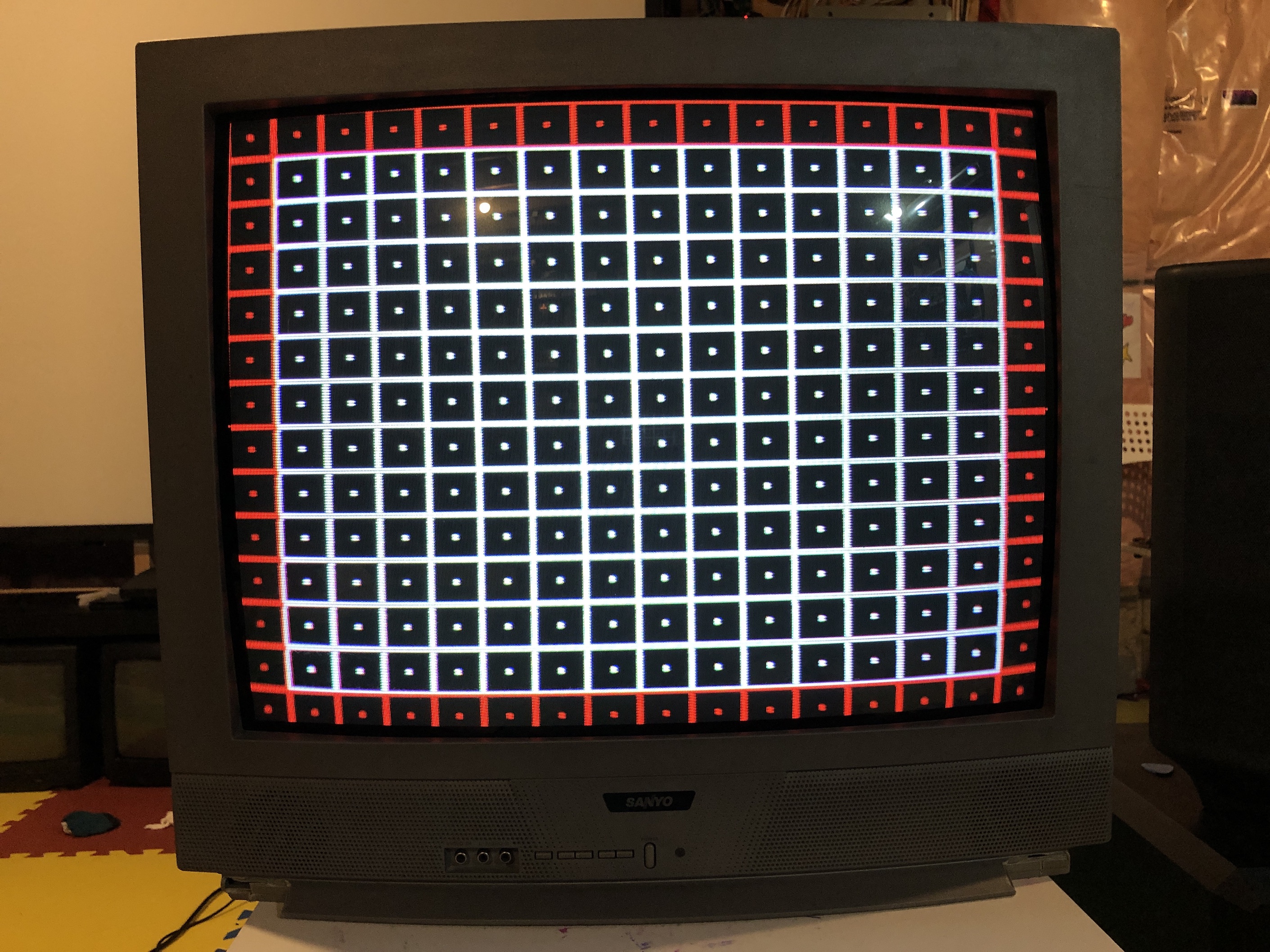
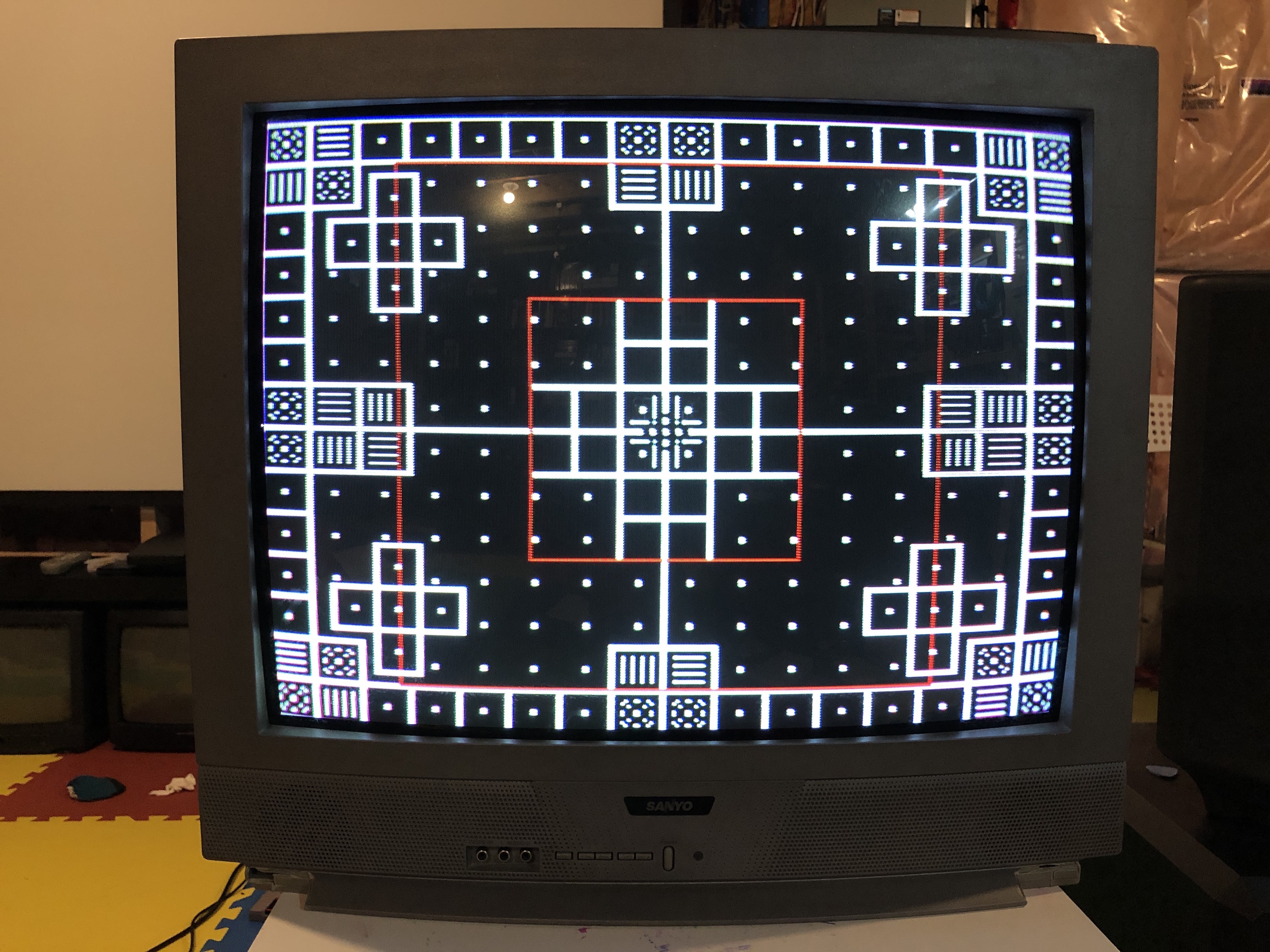
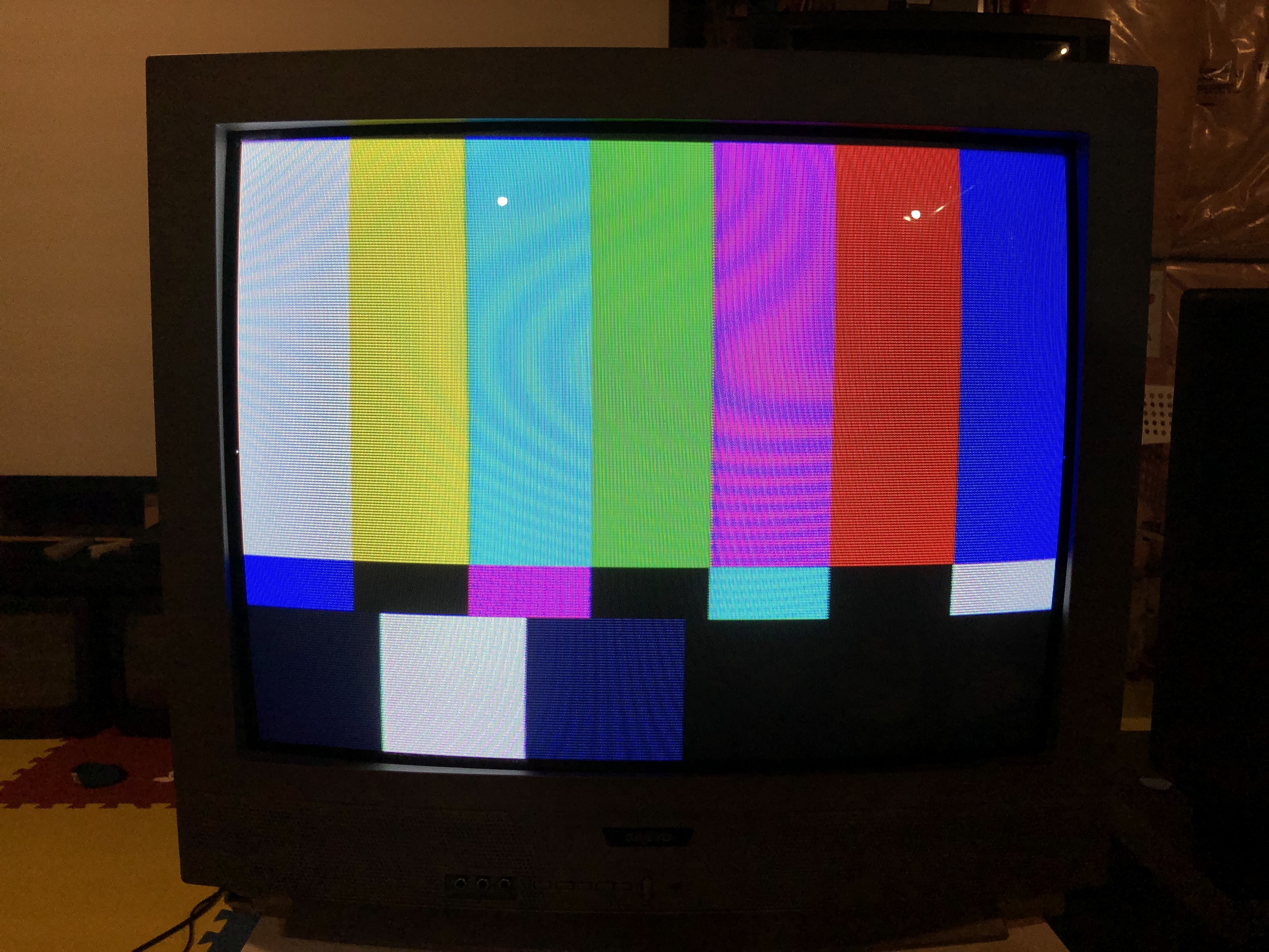
Games
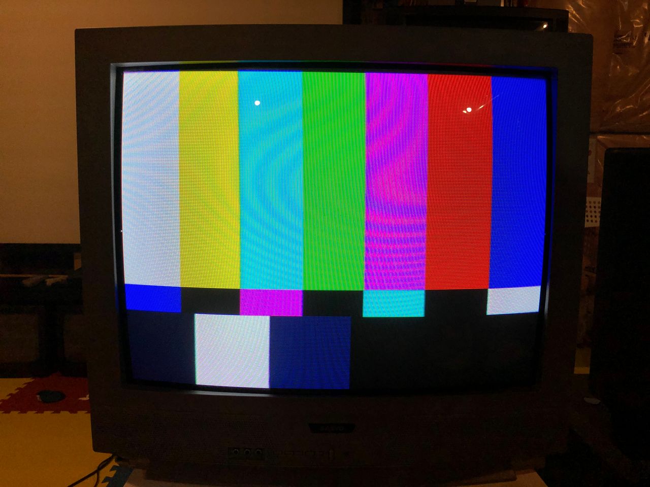
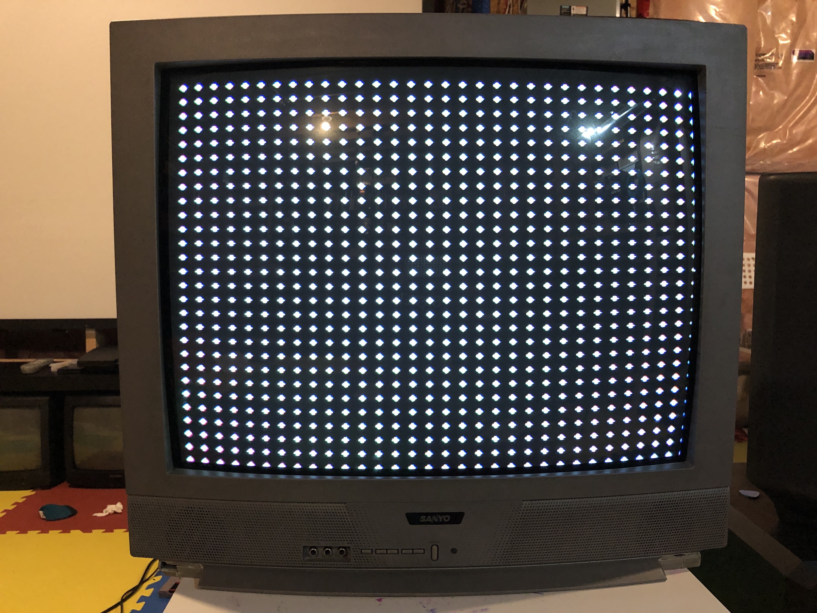
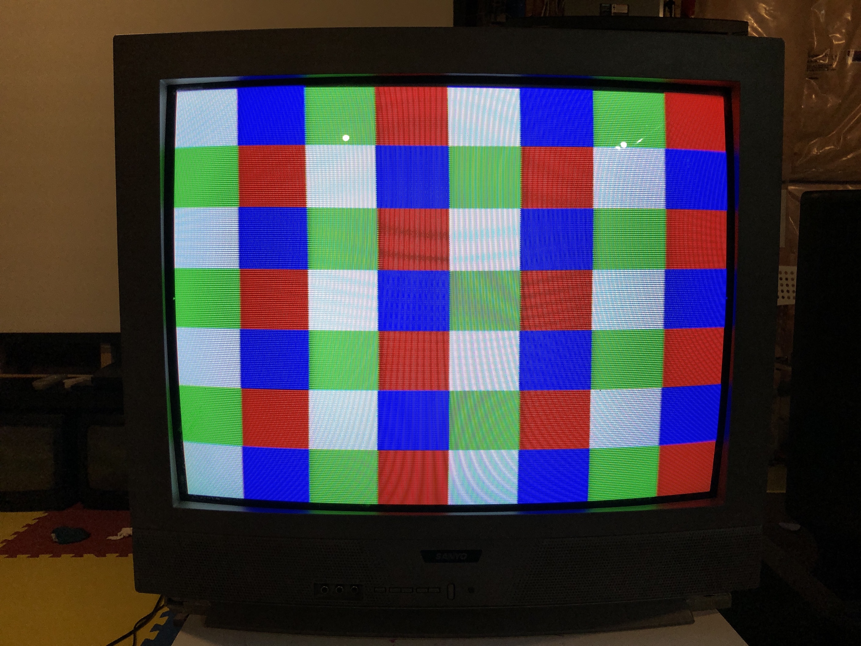
Patterns
Chassis, Tube and Casing
Tube label 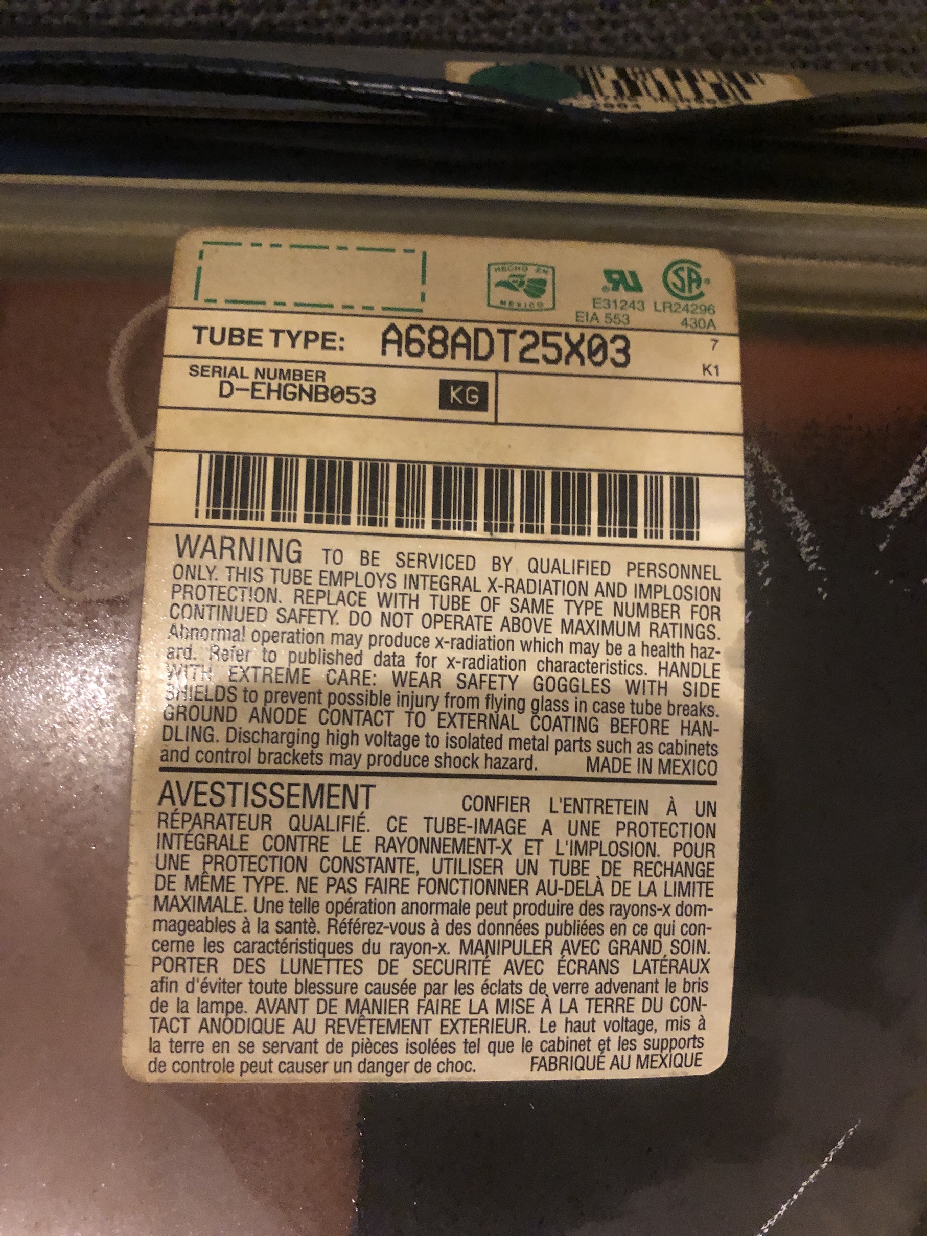
TV back label 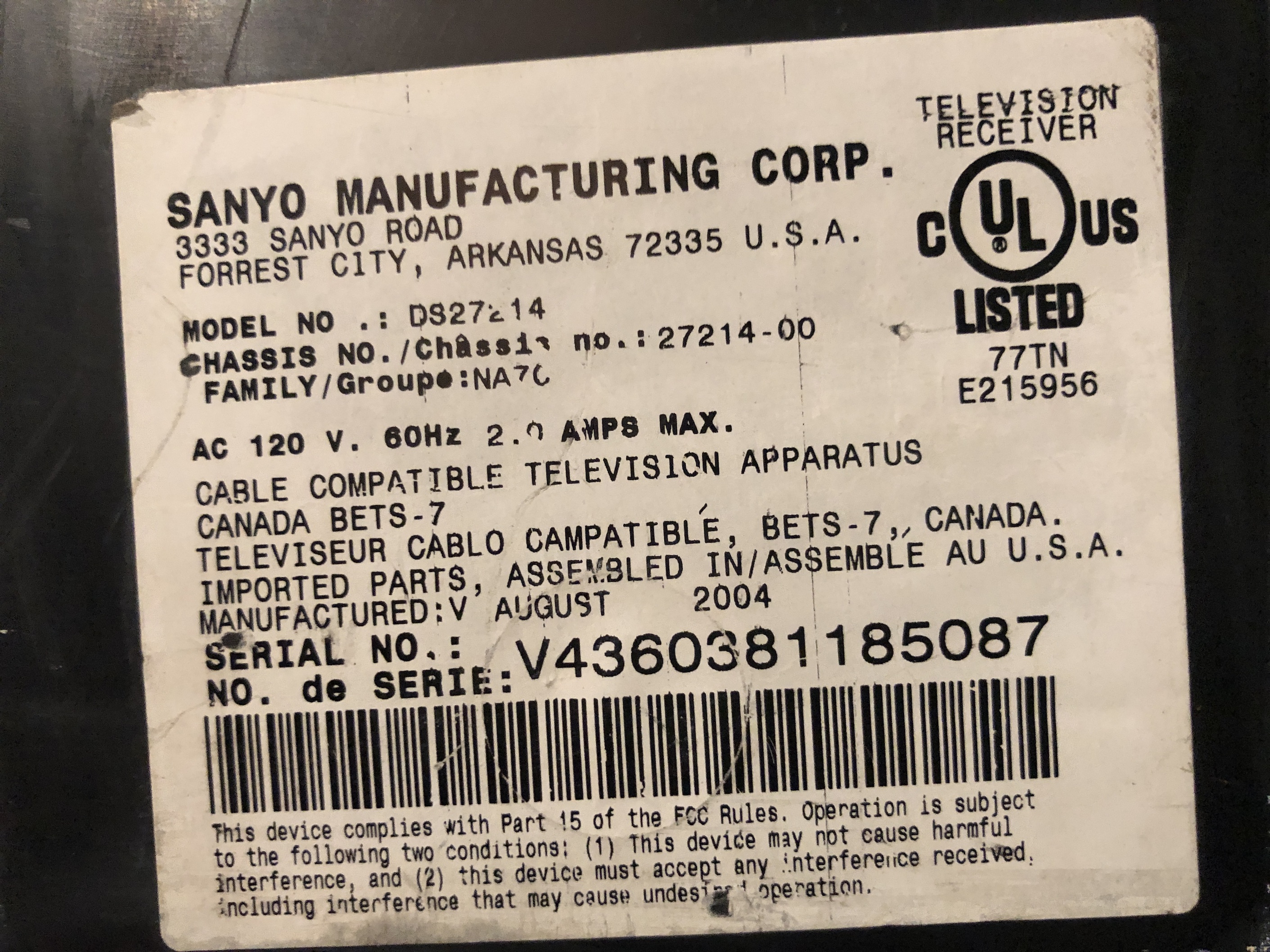
TV full back 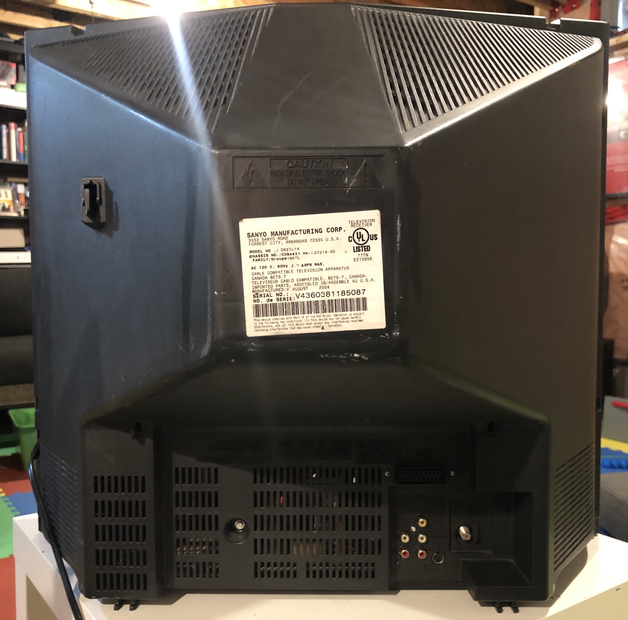
TV front buttons 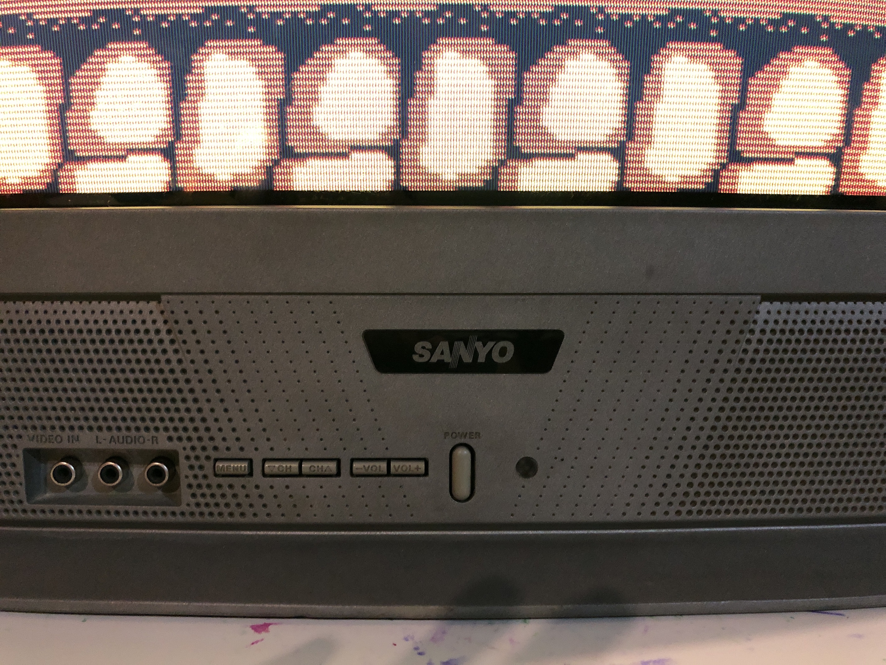
Chassis 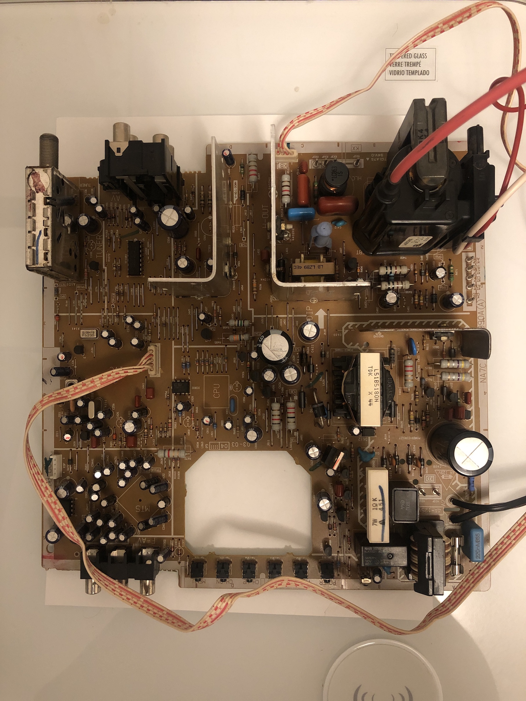
Neckboard - component side 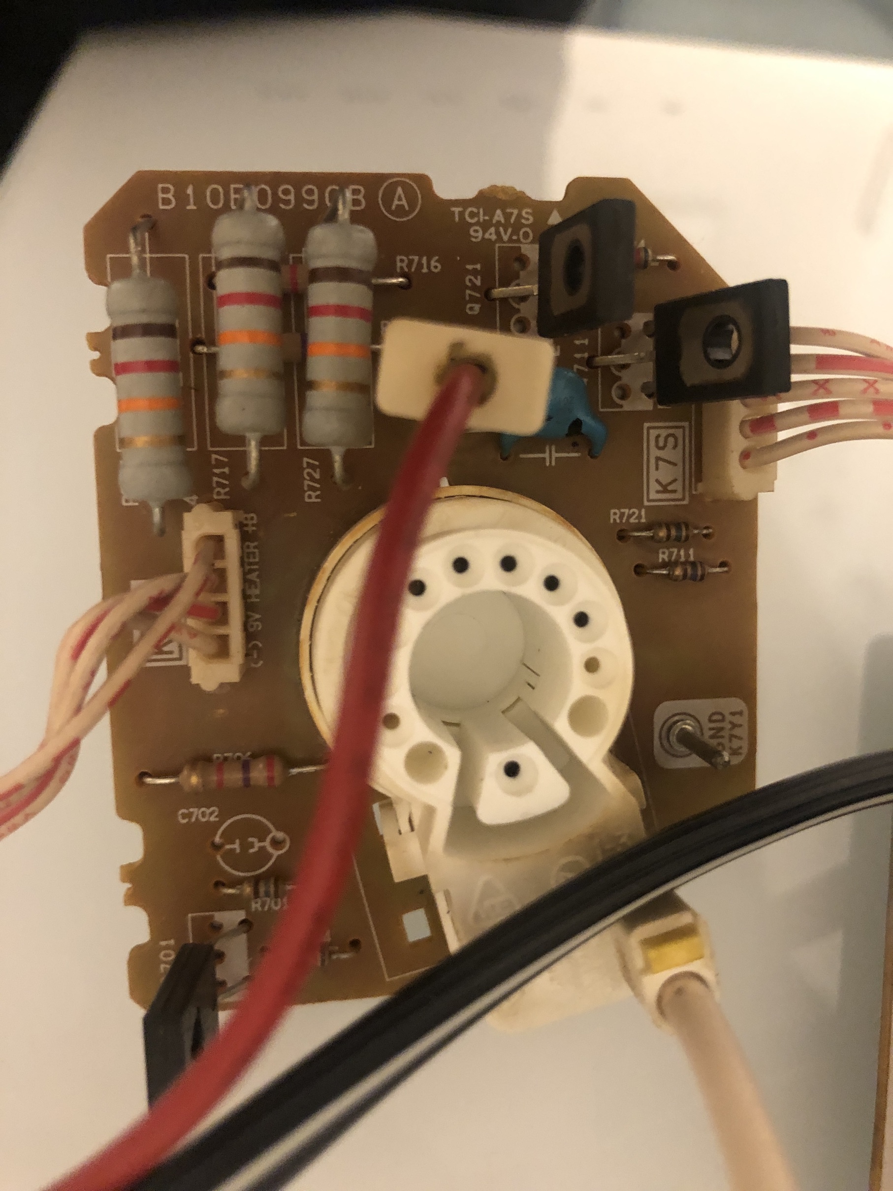
Neckboard - solder side 
Service menu settings
| NO. | TITLE | SANYO | ADJUSTED | RANGE OF DATA | FUNCTION |
|---|---|---|---|---|---|
| 1 | HFR | 29 | 0~63 | Horizontal Frequency | |
| 2 | AFC | 0 | 0, 1 | AFC Gain & Gate | |
| 3 | HP | 15 | 15 | 0~31 | Horizontal Phase (Horizontal Centering) |
| 4 | VS | 66 | 69 | 0~127 | Vertical Size |
| 5 | VPO | 5 | 0~63 | Vertical Position | |
| 6 | VSP | 0 | 0, 1 | Vertical Set Up (Sync Sensitivity) | |
| 7 | VLN | 15 | 0~31 | Vertical Linearity | |
| 8 | CRS | 0 | 0~3 | Cross B/W | |
| 9 | GRY | 1 | 0, 1 | Gray Mode | |
| 10 | VSC | 13 | 0~31 | Vertical S Correction | |
| 11 | HBR | 3 | 0~7 | H BLK R | |
| 12 | HBL | 3 | 0~7 | H BLK L | |
| 13 | CDM | 0 | 0, 1 | C D Mode | |
| 14 | VC | 7 | 0~7 | Vertical Compression | |
| 15 | RB | 12 | 200 | 0~255 | Red Bias |
| 16 | GB | 0 | 180 | 0~255 | Green Bias |
| 17 | BB | 2 | 179 | 0~255 | Blue Bias |
| 18 | RD | 75 | 55 | 0~127 | Red Drive |
| 19 | GD | 11 | 6 | 0~15 | Green Drive |
| 20 | BD | 73 | 59 | 0~127 | Blue Drive |
| 21 | SBI | 48 | 55 | 0~127 | Sub Bias |
| 22 | OSD | 3 | 1 | 0~3 | OSD Contrast |
| 23 | POS | 0 | 0, 1 | Pre/Over SW | |
| 24 | FLS | 1 | 0~7 | Filter System | |
| 25 | CKO | 3 | 0~7 | Color Killer Operation | |
| 26 | GYA | 0 | 0, 1 | G-Y Angle | |
| 27 | CRG | 2 | 0~3 | Coring Gain | |
| 28 | PRE | 3 | 0~3 | Pre Shoot Adjust | |
| 29 | WP | 1 | 0, 1 | White Peak Limiter | |
| 30 | FSW | 0 | 0, 1 | FBP Blanking Switch | |
| 31 | VBL | 0 | 0, 1 | Vertical Blanking Switch | |
| 32 | BSG | 2 | 0~3 | Black Str Gain | |
| 33 | BSS | 0 | 0~3 | Black Str Start | |
| 34 | DCR | 1 | 0~3 | DC Reset | |
| 35 | YGM | 1 | 0~3 | Y Gamma | |
| 36 | CBP | 0 | 0, 1 | C Bypass | |
| 37 | AF | 1 | 0 | 0, 1 | Auto Flesh |
| 38 | BAT | 4 | 0~7 | Bright ABL Threshold | |
| 39 | MSD | 0 | 0, 1 | Mid Stop Def | |
| 40 | ABL | 0 | 0, 1 | Auto Bright Limit | |
| 41 | RYA | 2 | 0~15 | R-Y/B-Y Angle | |
| 42 | RAD | 40 | 0~63 | RF AGC Delay | |
| 43 | IAS | 0 | 0, 1 | IF AGC | |
| 44 | FMM | 0 | 0, 1 | FM Mute | |
| 45 | FL | 15 | 0~31 | FM Level | |
| 46 | VL | 0 | 0~7 | Video Level | |
| 47 | EWD | 0 | 0~63 | EW DC | |
| 48 | EWA | 0 | 0~63 | EW Amp | |
| 49 | EWT | 0 | 0~63 | EW Tilt | |
| 50 | EWP | 0 | 0~7 | EW Corner Top | |
| 51 | EWB | 0 | 0~7 | EW Corner Bottom | |
| 52 | HSC | 7 | 0~7 | Horz Size Comp | |
| 53 | SB | 24 | 0 | 0~63 | Sub Bright |
| 54 | SCO | 14 | 14 | 0~31 | Sub Color |
| 55 | STI | 24 | 20 | 0~31 | Sub Tint |
| 56 | SSH | 12 | 0~31 | Sub Sharpness | |
| 57 | OPT | 100 | 0~255 | Option (See Note 1 page 6.) | |
| 58 | OP2 | 32 | 0~255 | Option 2 (See Note 2 page 6.) | |
| 59 | HR | 22 | 0~63 | OSD Horizontal Position | |
| 60 | ATT | 7 | 0~63 | Input Level | |
| 61 | WDB | 35 | 0~63 | Wideband | |
| 62 | SPC | 12 | 0~63 | Spectral | |
| 63 | SBO | 5 | 0~255 | Sub Bright Offset | |
| 64 | PCO | 40 | 0~63 | PIP Color | |
| 65 | PTI | 40 | 0~63 | PIP Tint | |
| 66 | PUV | 24 | 0~63 | PIP Top Position | |
| 67 | PDV | 147 | 0~255 | PIP Bottom Position | |
| 68 | PLH | 10 | 0~63 | PIP Left Position | |
| 69 | PRH | 101 | 0~255 | PIP Right Position | |
| 70 | PCN | 52 | 0~63 | PIP Y Level | |
| 71 | PBS | 15 | 0~63 | PIP BGP Phase |