Sony (AA-2C) KV-32XBR48
Sony (AA-2C) KV-32XBR48 CRT RGB mod
The Sony KV-32XBR48 is a 32" curved Trinitron CRT television. Released in the late 1990s as a high-end XBR model, it is recognized for its component video inputs and curved screen, a rare combination.
View full CRT details and more mod examples →
This tutorial is also applicable for the below models:
- Sony KV-32XBR48
- Sony KV-35XBR48
Table of Contents
Contributors
Thank you to everyone who contributed to this guide:
- Kaz Packman — contributor, RGB mod and pictures
CRT safety
Caution
You can die doing this! So read carefully! CRT TV is not a toy. Do not open a CRT TV. If you don't have any prior knowledge about handling high voltage devices, this guide is not for you. CRT TV contains high enough voltage (20,000+ V) and current to be deadly, even when it is turned off.
Plan of attack
Manuals and Datasheets
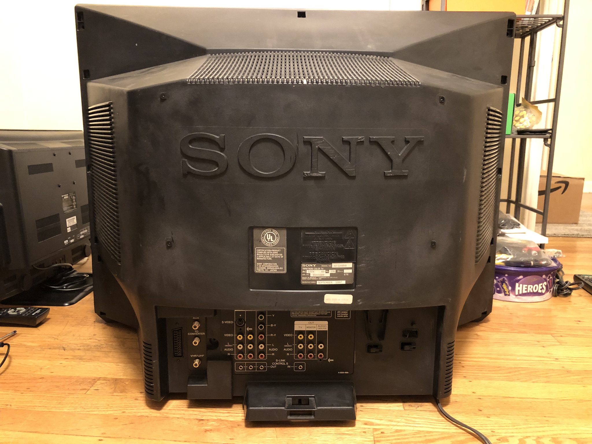
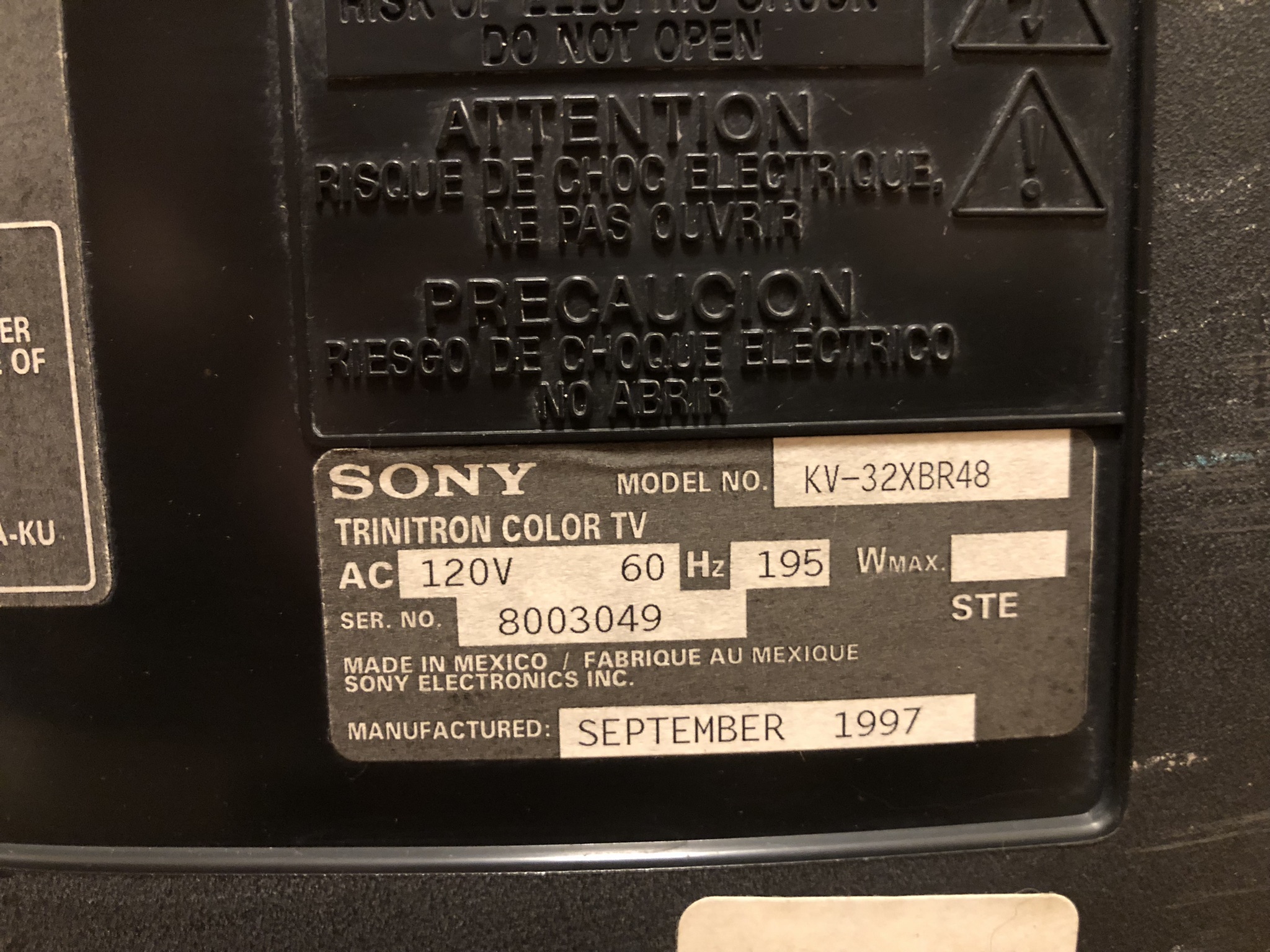
Specs
- Manufactured: Mexico (1997)
- Chassis: AA-2C
- Tube: Sony FD Trinitron M80JYV51X
- Jungle Chip: Sony CXA2025AS
- OSD Chip: CXP85856A-001S
- Power: 195 W
RGB mux diagram
Prepare the mux diagram. If you are building your own circuit, this diagram should help.
Performing the mod
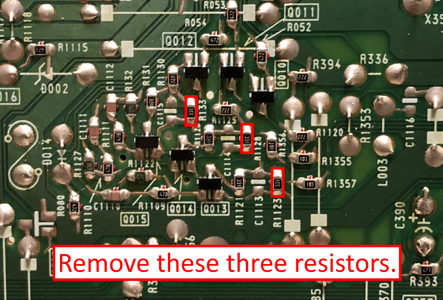
STEP 1: Remove the following components
- R1123
- R1128
- R133
STEP 2: Connect RGB and blanking wires
Inject R, G, B where the resistors were removed, but on the pad that is not connected to the ground.
![]()
STEP 3: Add a diode to blanking
Add this diode to reduce interference.
![]()
With diodes, direction matters. Please make sure to install it such that the stripe is pointing towards the chroma/jungle chip. The idea here is to make sure external blanking current doesn't reach the OSD chip.
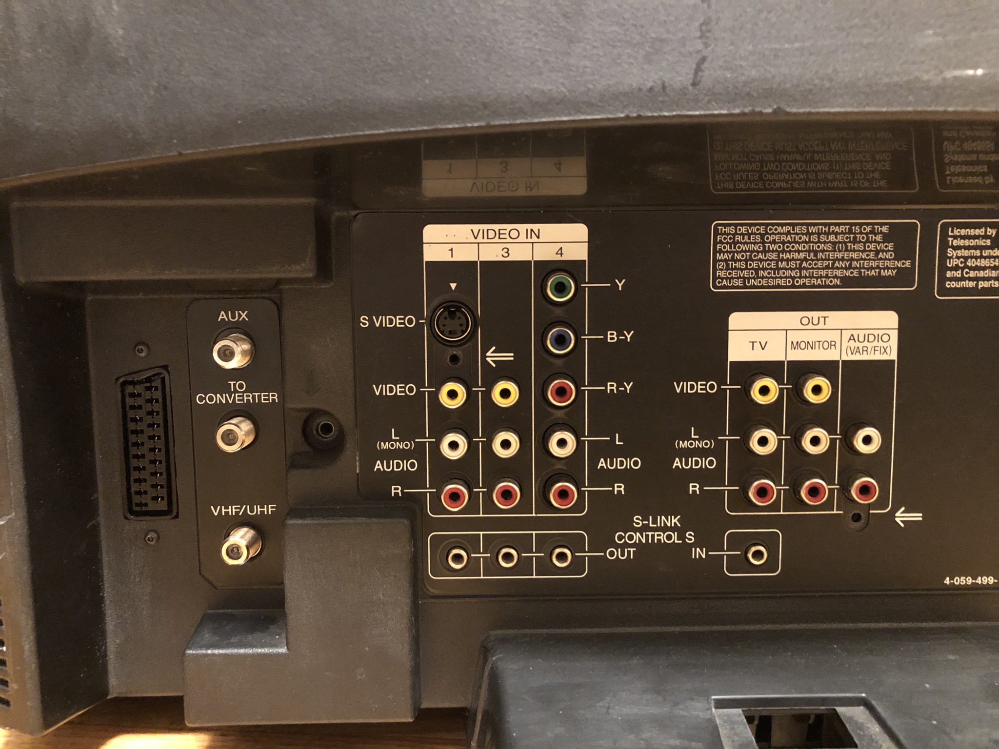
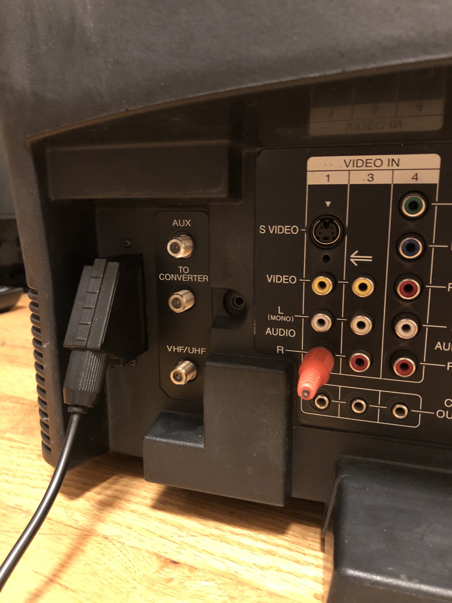
STEP 4: Connect audio and sync wires
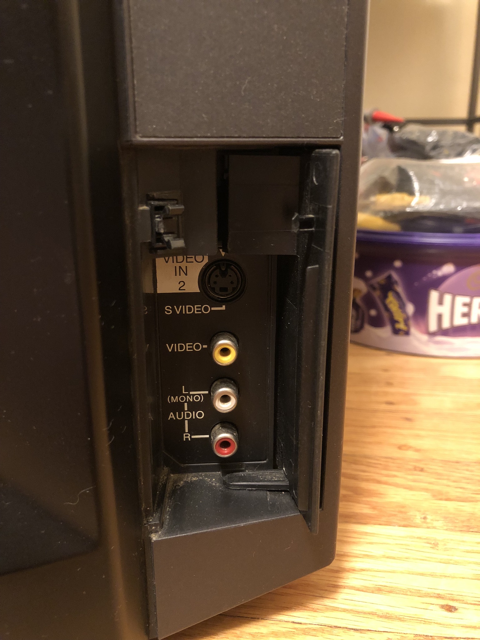
For this mod, the Video 1 S-Video input was used for Sync and audio injection. For the S-Video input to work for this purpose, a jumper wire was soldered between the two shield pads of the connector as seen in the picture.
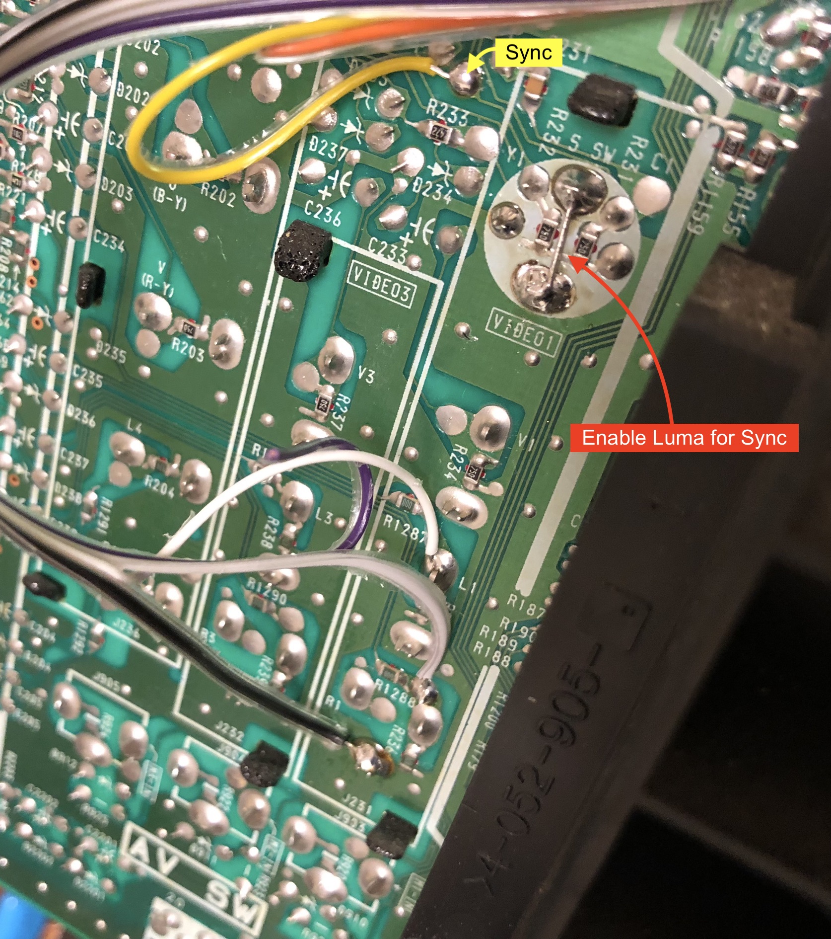
Alternatively, you can inject Sync into the Video 4 Component Luma input and audio into its respective audio input pads if you wish to use that input for RGB instead. A dummy RCA plug was connected to the Right Audio input to preserve Stereo functionality when using RGB SCART.
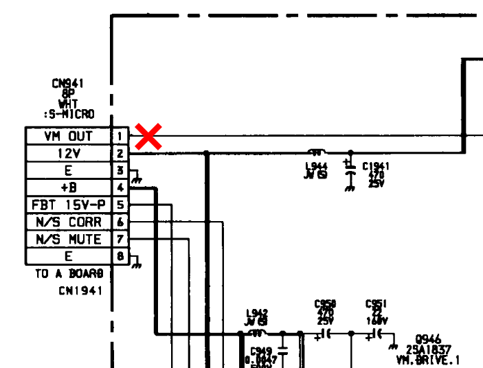
STEP 5: Disconnect VM wires to reduce artificial sharpening
This set uses Velocity Modulation (VM), which can degrade the picture quality if not disconnected. It cannot be disabled in neither the user settings nor service menu, so it must be disconnected physically from the set.
You can do this in either one of two ways:
Method 1: Permanently disconnect the 8-pin cable coming from CN941 on the WA board, which is the board on the CRT neck placed between the deflection yoke and the neckboard.
Method 2: Remove the white wire from the 8-pin cable coming from CN941 on the WA board. To do this, unplug the cable from the WA board, place a pointed object in the catch on the plastic housing where the pin is located, pull out the wire from the connector housing while holding the pointed object in the catch to release it, then plug the cable back into the WA board without the white wire connected. It would be a good idea to isolate the metal crimp on the wire with Kapton tape to avoid shorting it out.
STEP 6: Build your mux circuit
This mod uses the RGB mux board. This is optional, but will make your mod easier and stable. You can also create the circuit presented in the schematics above without the board. Please also checkout the mux calculator to play with your own values.
| On Sony CRT Chassis | KV-32XBR48 |
|---|---|
| CRT RGB inline resistor | 2.2kΩ |
| CRT RGB ground resistors removed | 390Ω |
| 0.1μF caps replaced | No |
| Add diodes on chassis RGB lines? | No |
| Add blanking diode on chassis | Yes |
| RGB mux board | KV-32XBR48 |
|---|---|
| Mux board RGB termination (R1, R2, R3) | 75Ω |
| Mux board RGB inline resistors (R4, R5, R6) | 330Ω |
| Mux board Audio LR (R7, R8) | 1kΩ |
| Mux board blanking diode (R9) | 1N4148 |
| Mux board blanking ground resistor (R10) | 330Ω |
| Mux board blanking resistor (R11) | 470Ω |
| Mux board transistor base resistor (R12) | 1kΩ |
| Mux board transistor (Q1) | PN2222A |
Compatible mux boards:
It is important to note that the blanking ground resistor (R10) is necessary to prevent strange black backgrounds from appearing on the KV-27S22 OSD text.
Picture of RGB mux rev B board 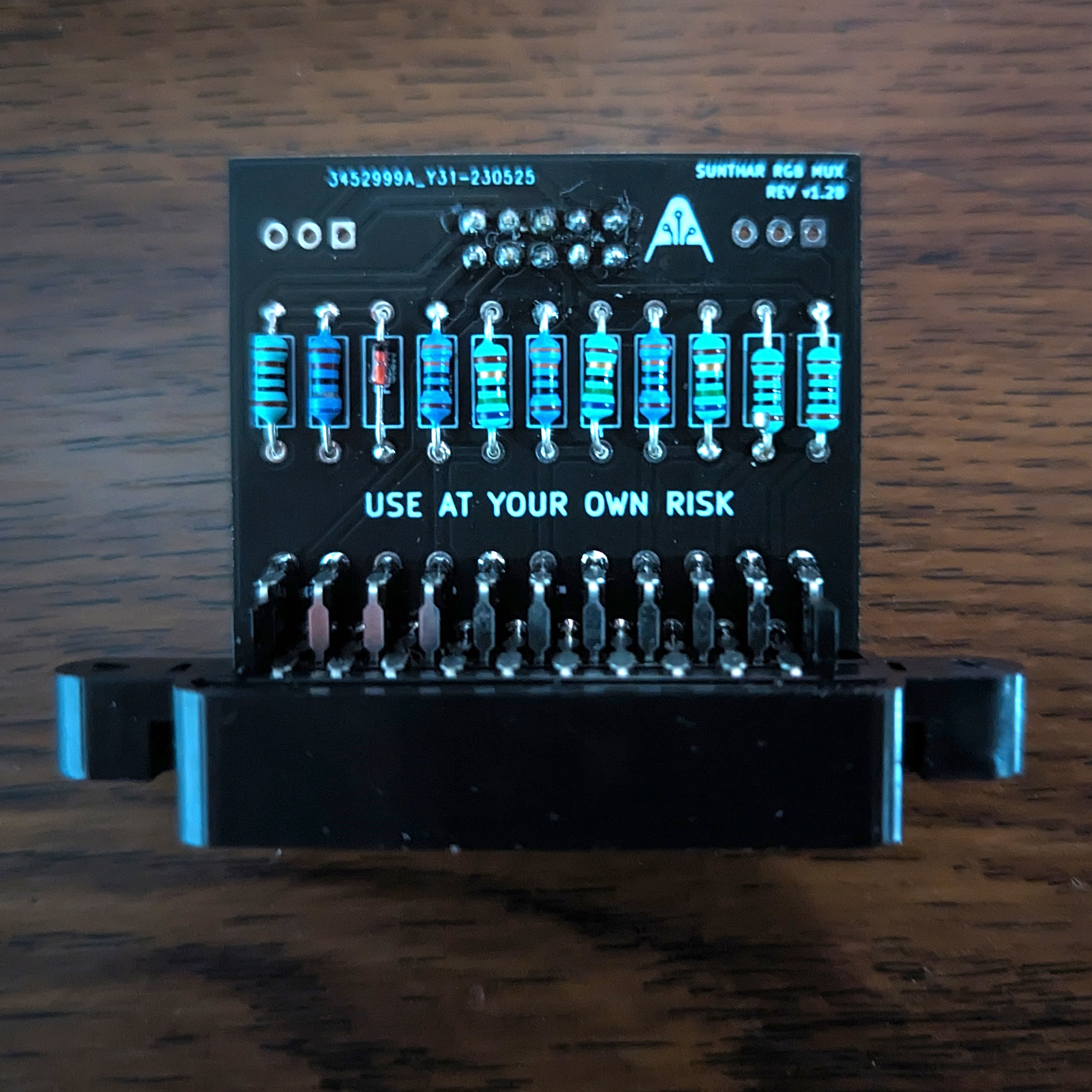
STEP 6: Attach the female SCART connector to TV
Creating a SCART cutout and mounting it is an art. I have a dedicated section for it. How to create and mount a SCART female plug?
Pictures
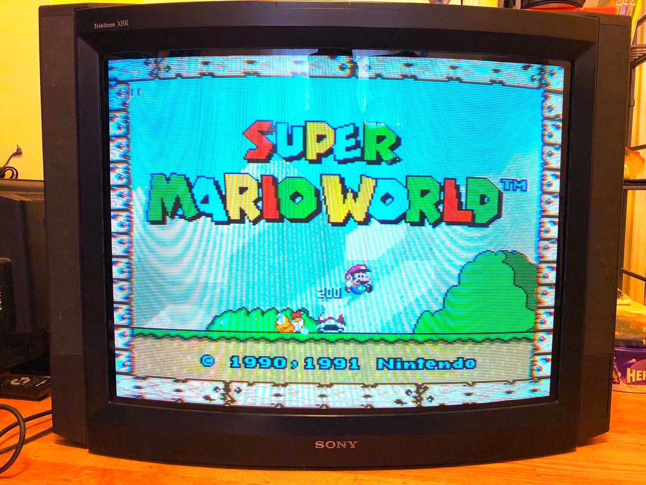
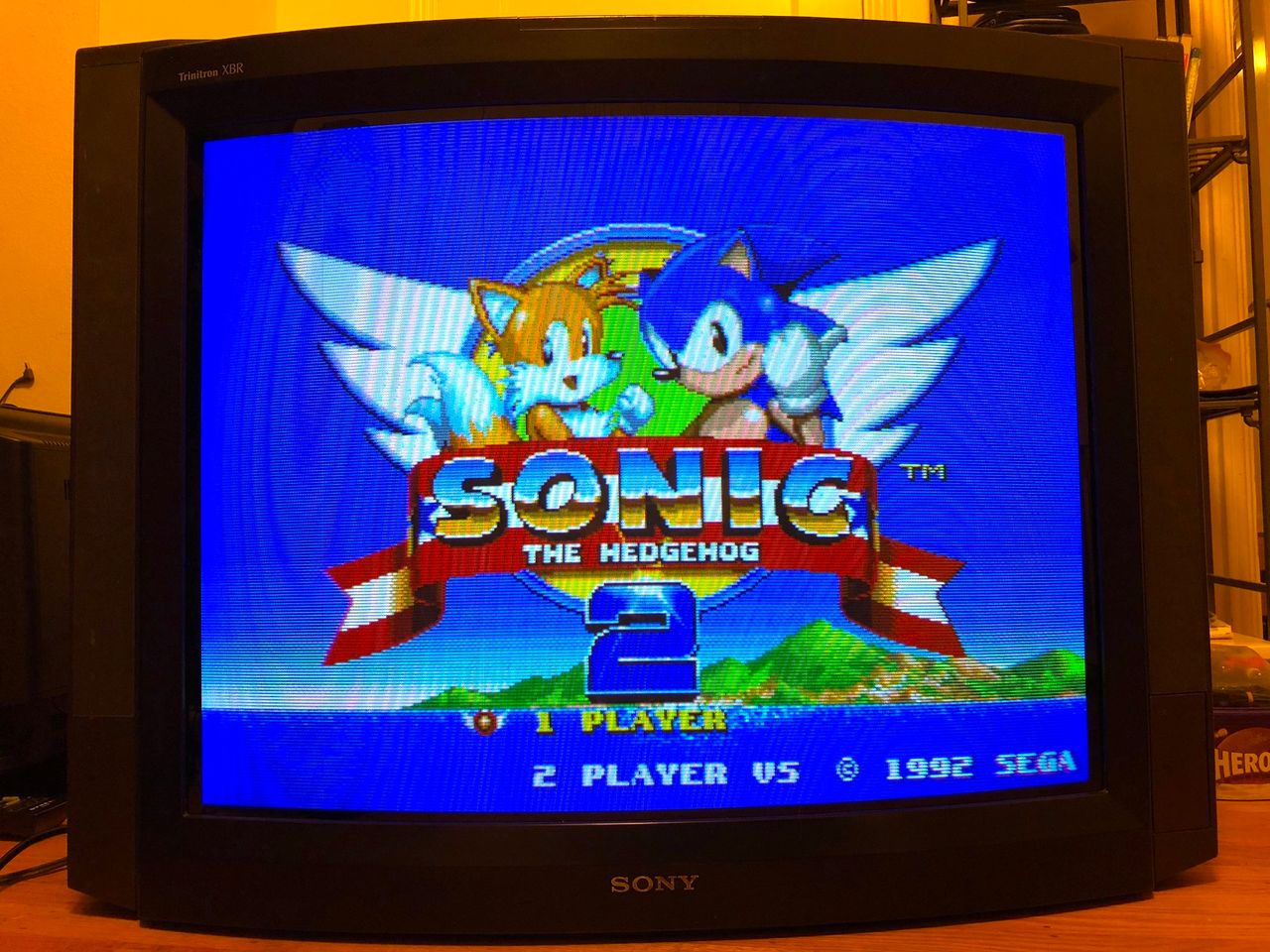
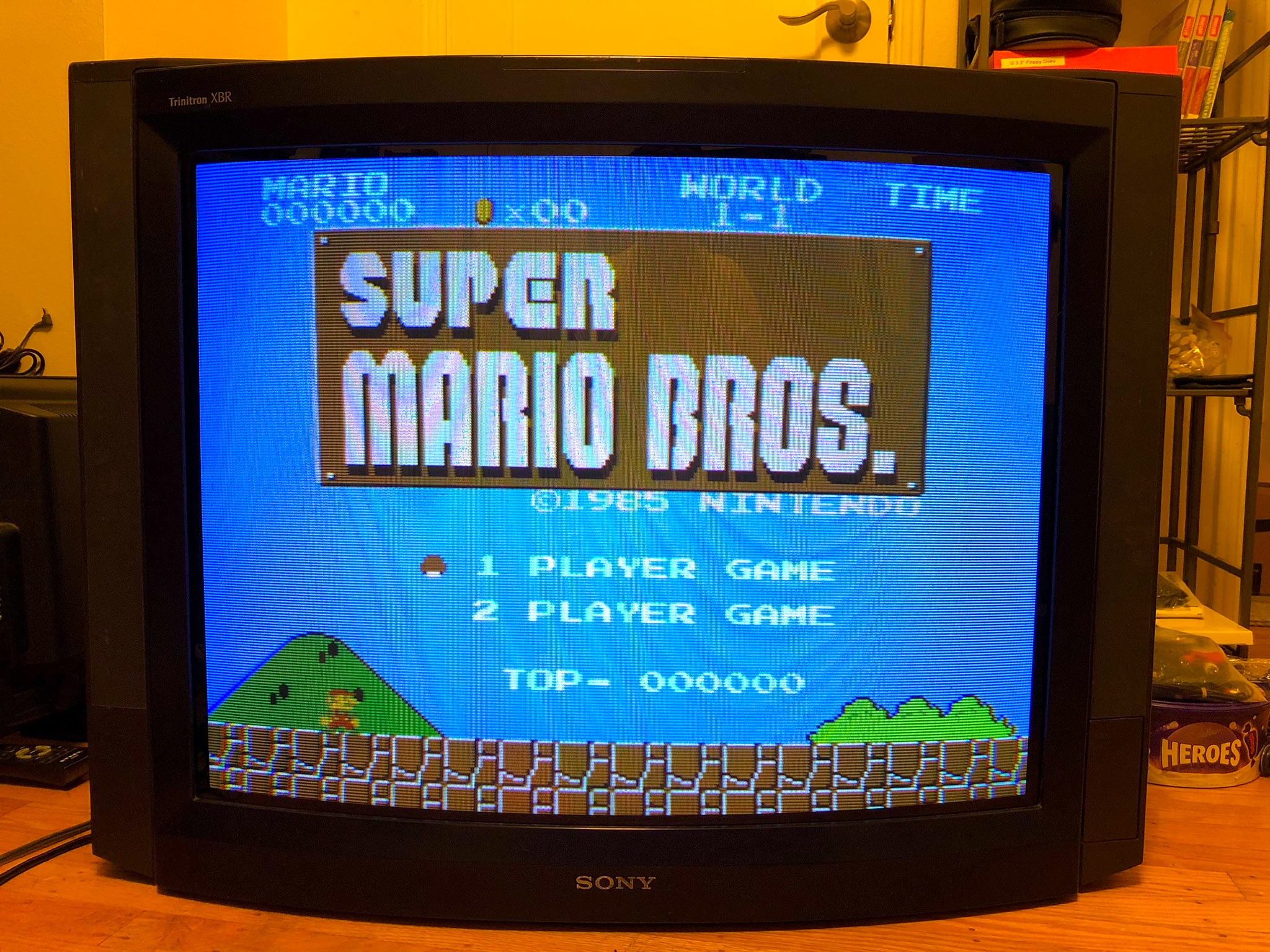
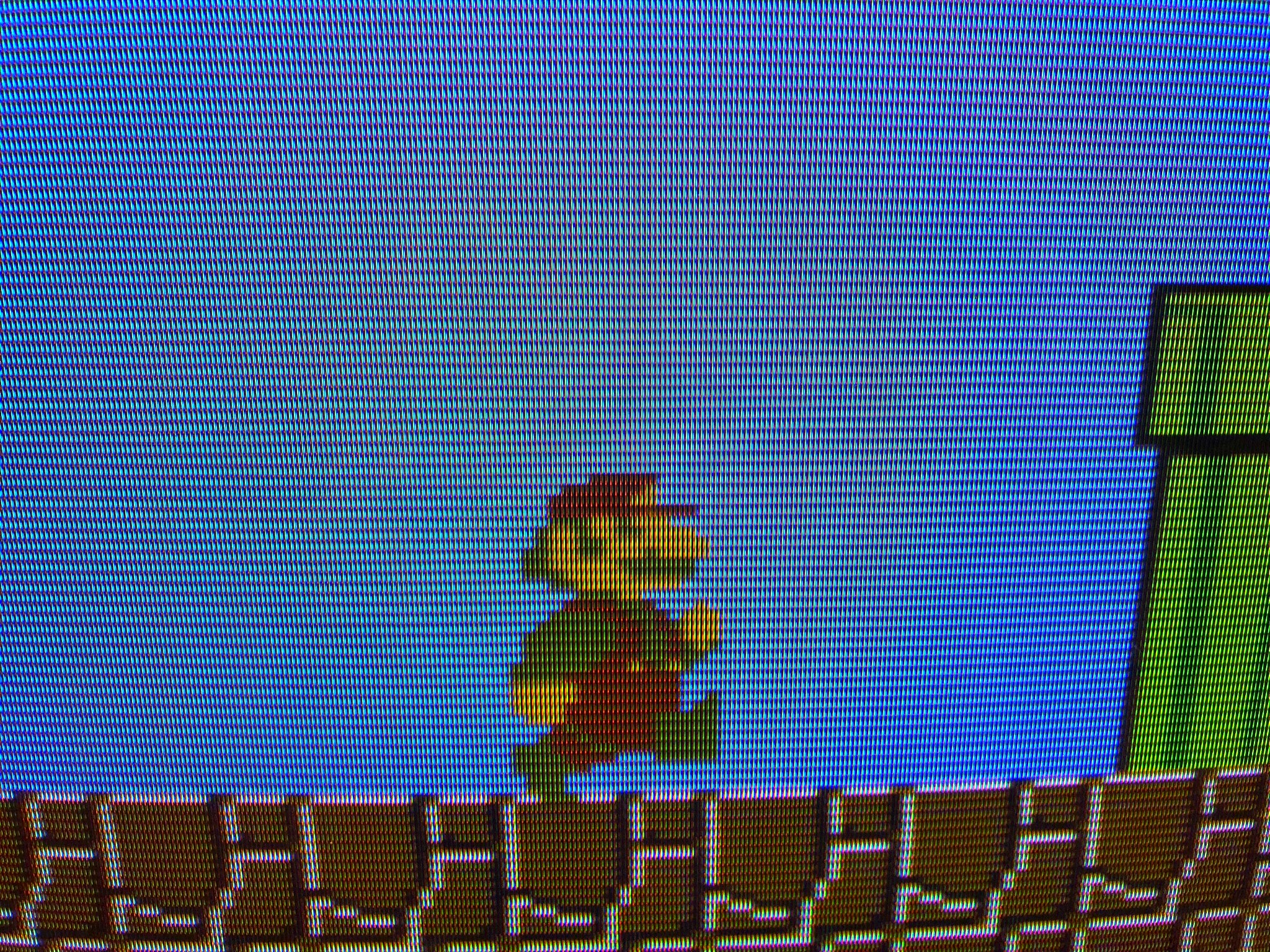
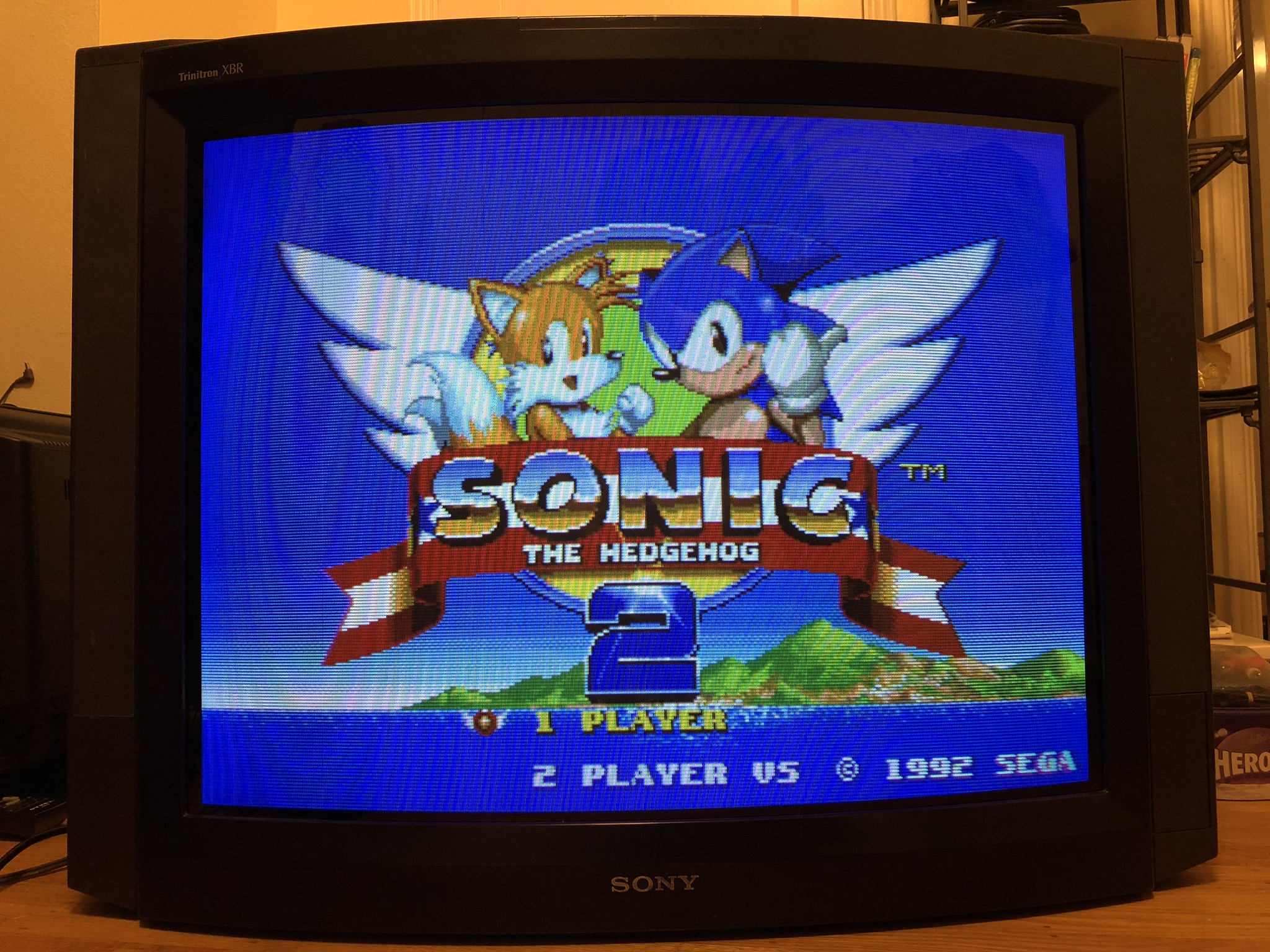
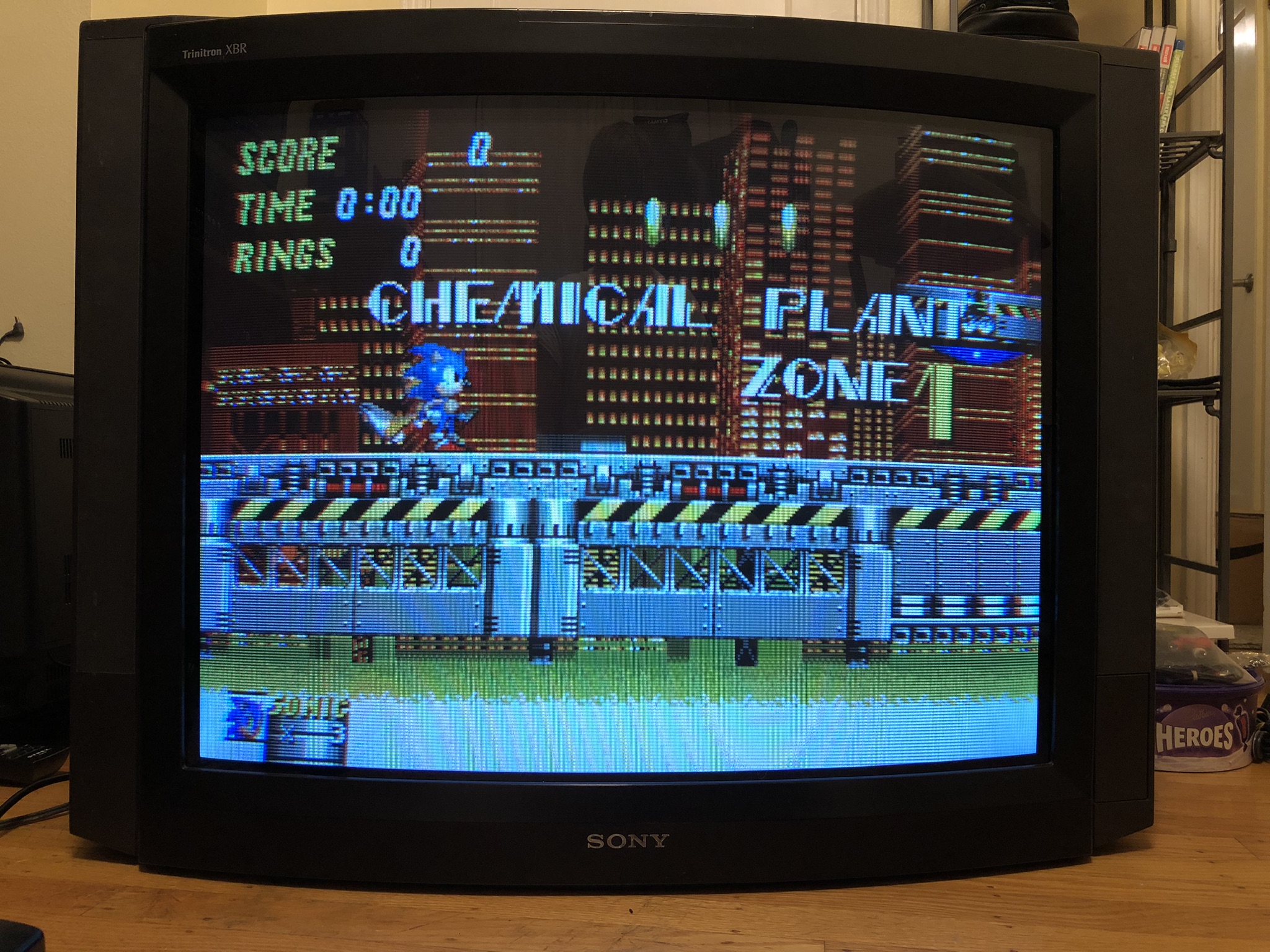
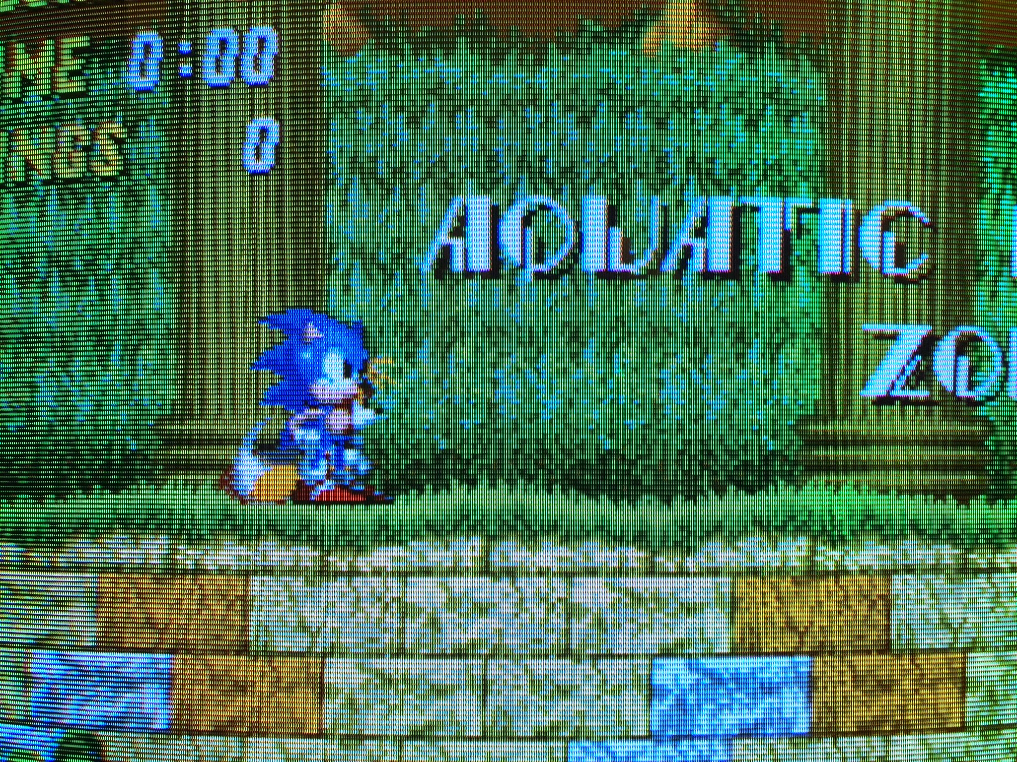
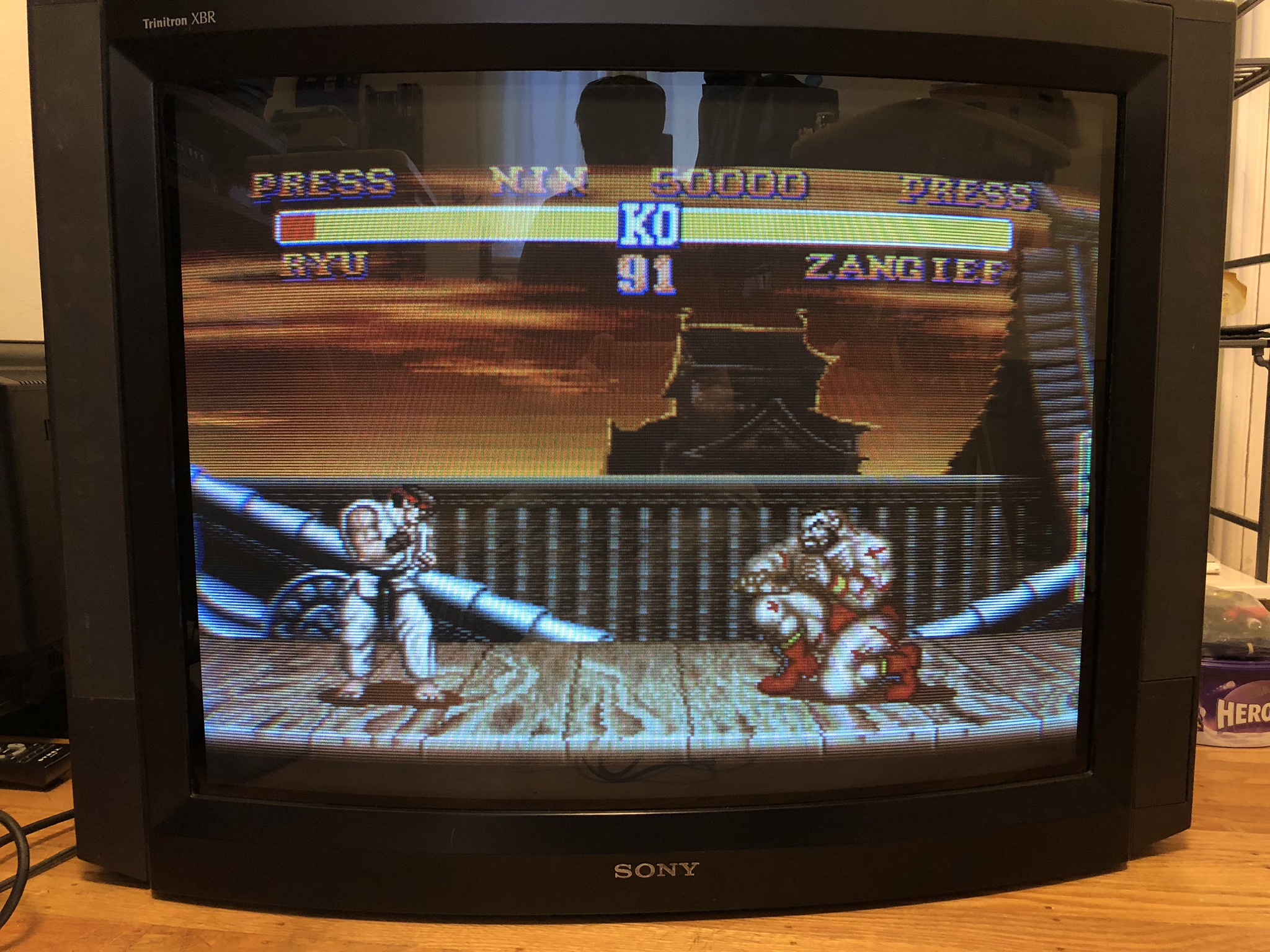
Games
Mux mod in action 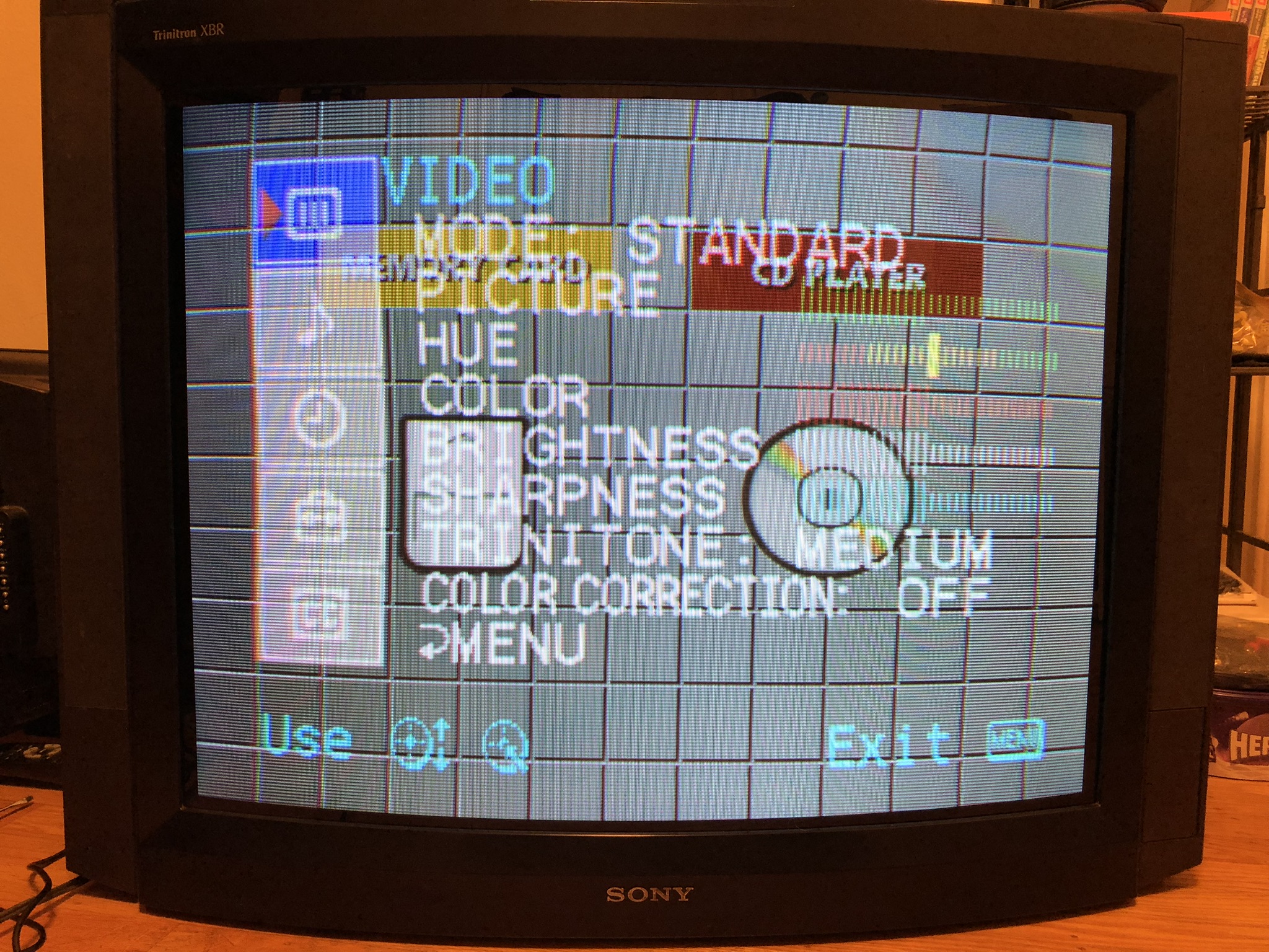
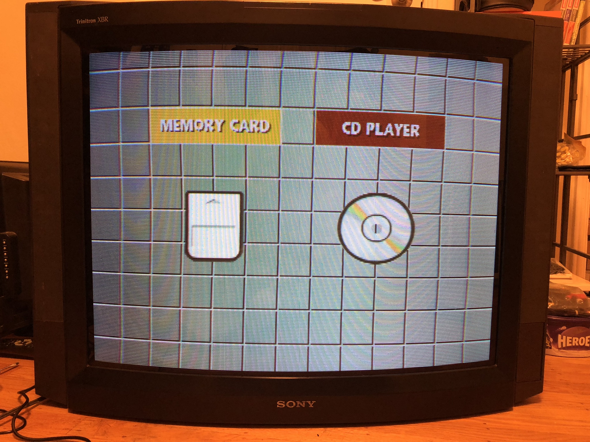
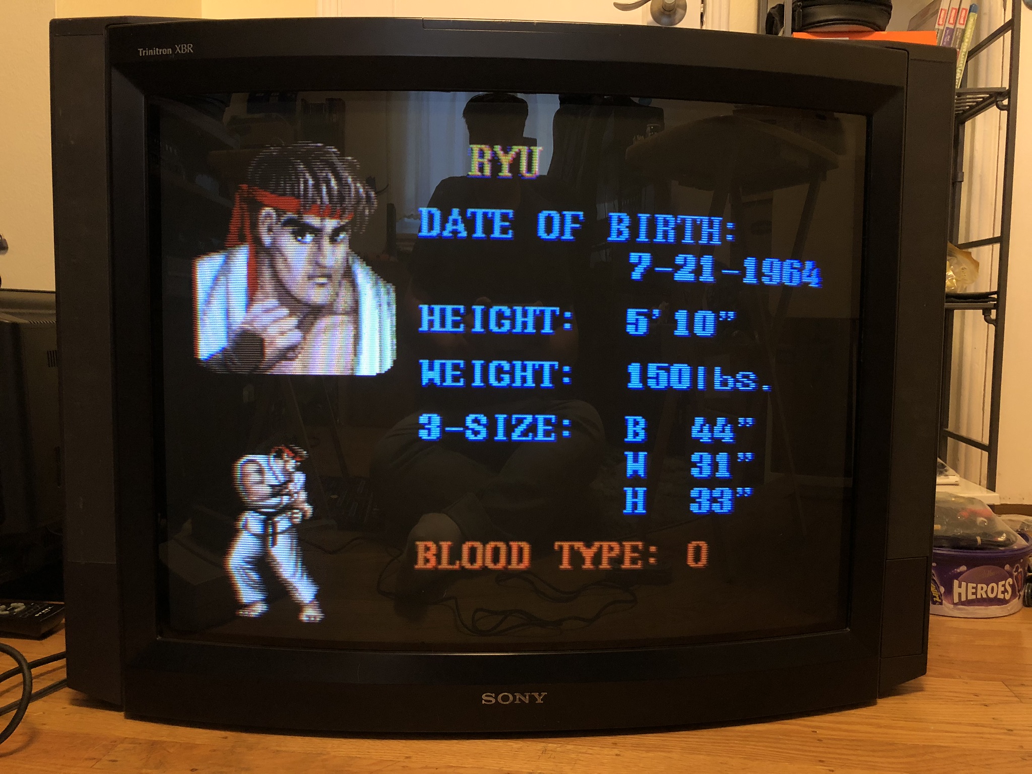
TV
Front 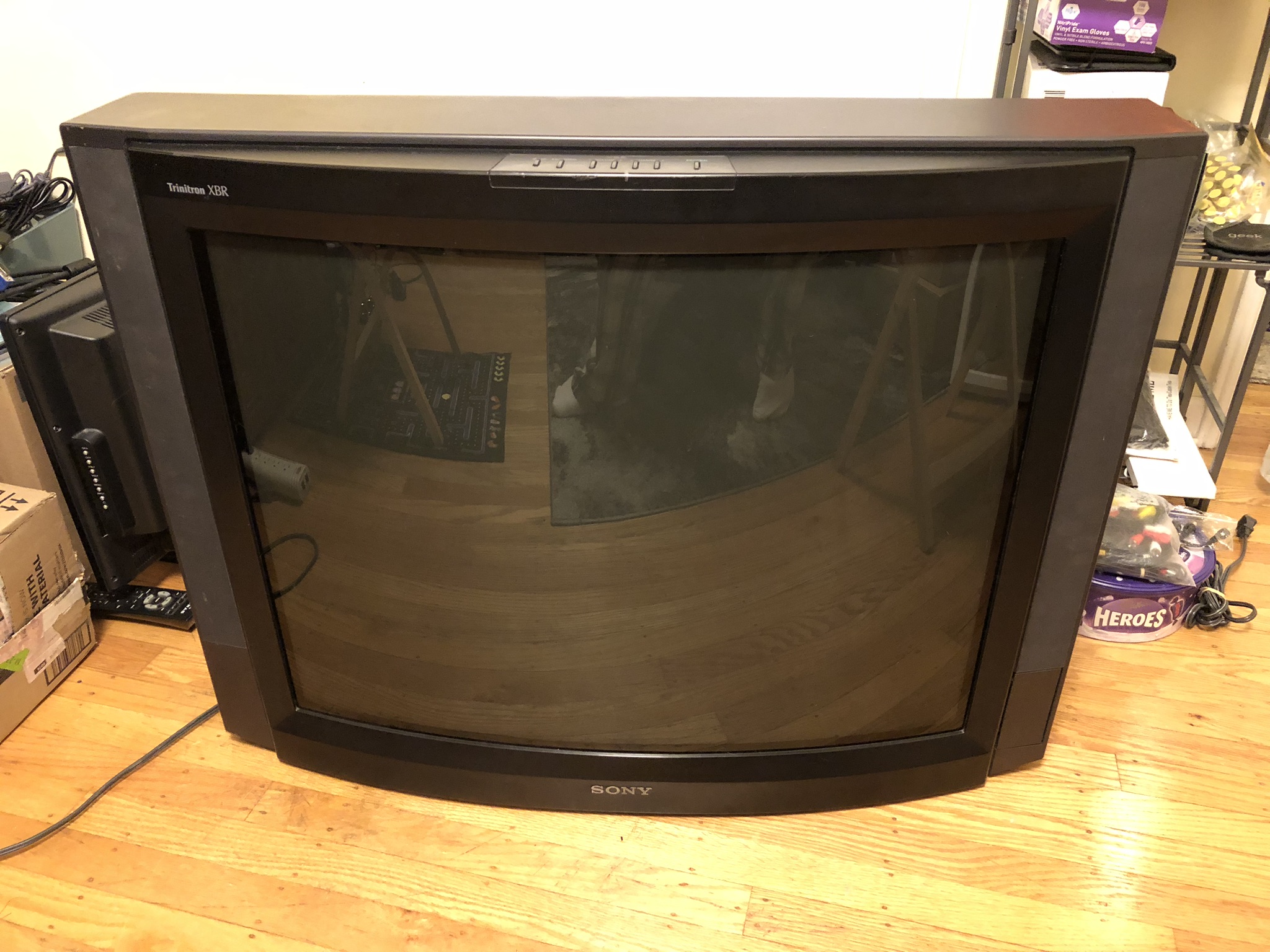
Pictures
Reference Photos