Sony (BG-1S) KV-G14P1RGB mod your Sony KV-G14P1 or any BG-1S chassis based Sony CRT.Kevin Smith's SectorAbout 6 minCRT RGB modKV-T29SZ1KV-T25MF1KV-T25MN1KV-T29CF1KV-T25SN81KV-G14P1KV-G14S1
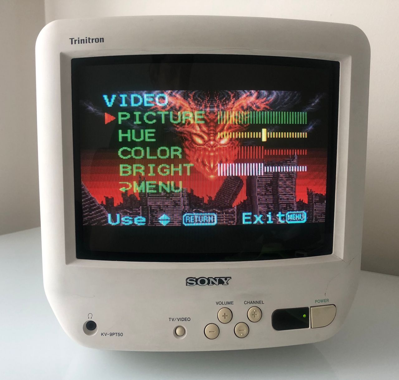
Sony (BN-1) KV-9PT50RGB mod your Sony KV-9PT50 or any BN-1 chassis based Sony CRT.SuntharAndy KingAbout 10 minCRT RGB modKV-9PT60KV-9PT50KV-10PR1
Sony (G3F) KV-F29MF1RGB mod your Sony KV-F29MF1 or any G3F chassis based Sony CRT.Retrogamer.aeRetroGamer.aeAbout 3 minCRT RGB modKV-F29MF1
Sony (BA-5) KV-20FV12RGB mod your Sony KV-20FV12 or any BA-5 chassis based Sony CRT.Dan LavoieWei LinMike MorisetteAbout 9 minCRT RGB modKV-13FM12KV-20FS12KV-13FM13KV-13FM14KV-20FV12KV-24FV12KV-27FS17KV-27FS12KV-27FS13KV-27FV17KV-32FS13KV-32FS12KV-32FS16KV-27FV16KV-27FS16KV-32FS17KV-14MF1KV-21FM12KV-14FM14KV-14FM12KV-25FV12KV-14FM12CKV-21FV12
Sony (BA-5D) KV-36FS100RGB mod your Sony KV-36FS100 or any BA-5D chassis based Sony CRT.Eli KrauseDevon SanchezAbout 3 minCRT RGB modKV-27FS100KV-27FS210KV-36FS210KV-27FV300KV-32FS100KV-32FS200KV-27FS200KV-27FV310KV-32FV300KV-32FV310KV-36FS100KV-36FS200KV-36FV310KV-36FV300KV-29FS100KV-29FA210
Sony (BG-1L) KV-J25MF8JRGB mod your Sony KV-J25MF8J or any BG-1L chassis based Sony CRT.SuntharAbout 5 minCRT RGB modKV-LX34M31KV-J29MF8JKV-J25MF8JKV-J29MF1KV-J29SZ2
Sony (BA-1) KV-13TR29RGB mod your Sony KV-13TR29 or any BA-1 chassis based Sony CRT.SuntharAndy KingAbout 15 minCRT RGB modKV-13TR29KV-20TS29KV-13TR28KV-20TR23KV-20TS50KV-13V50KV-20TS32KV-20V50