Sony (AA-2) KV-35V35
Sony (AA-2) KV-35V35 CRT RGB mod
You can find a highly detailed post about the AA-2 RGB mod in a separate article. This article delves into the distinctions of the KV-35V35 CRT, where its audio and video connectors are located on a daughter board. As a result, the connections for sync and audio need to be made in slightly different locations.
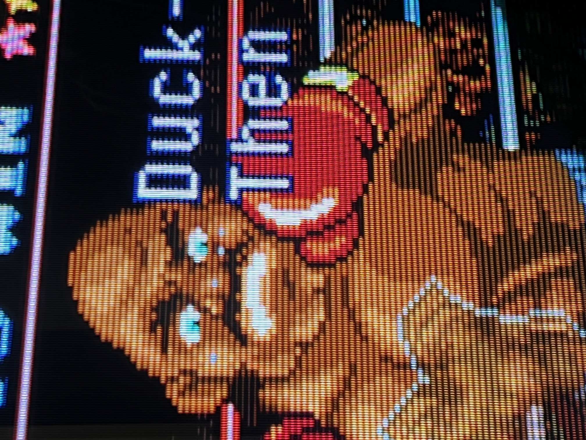
The Sony KV-35V35 is a massive, premium 35-inch CRT television released by Sony in the late 1990s.
View full CRT details and more mod examples →
Below instructions should also work for the below models.
- Sony KV-35V35
- Sony KV-35V45
- Sony KV-35V75
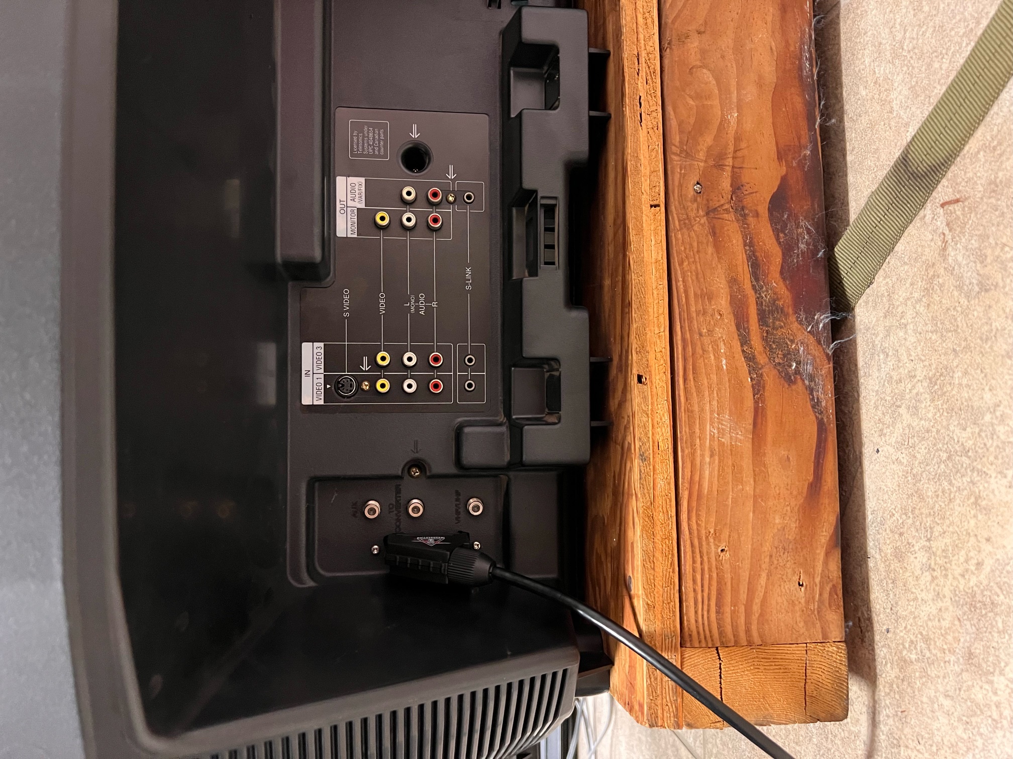
35" CRT is a real beast. This is a picture from the back view. 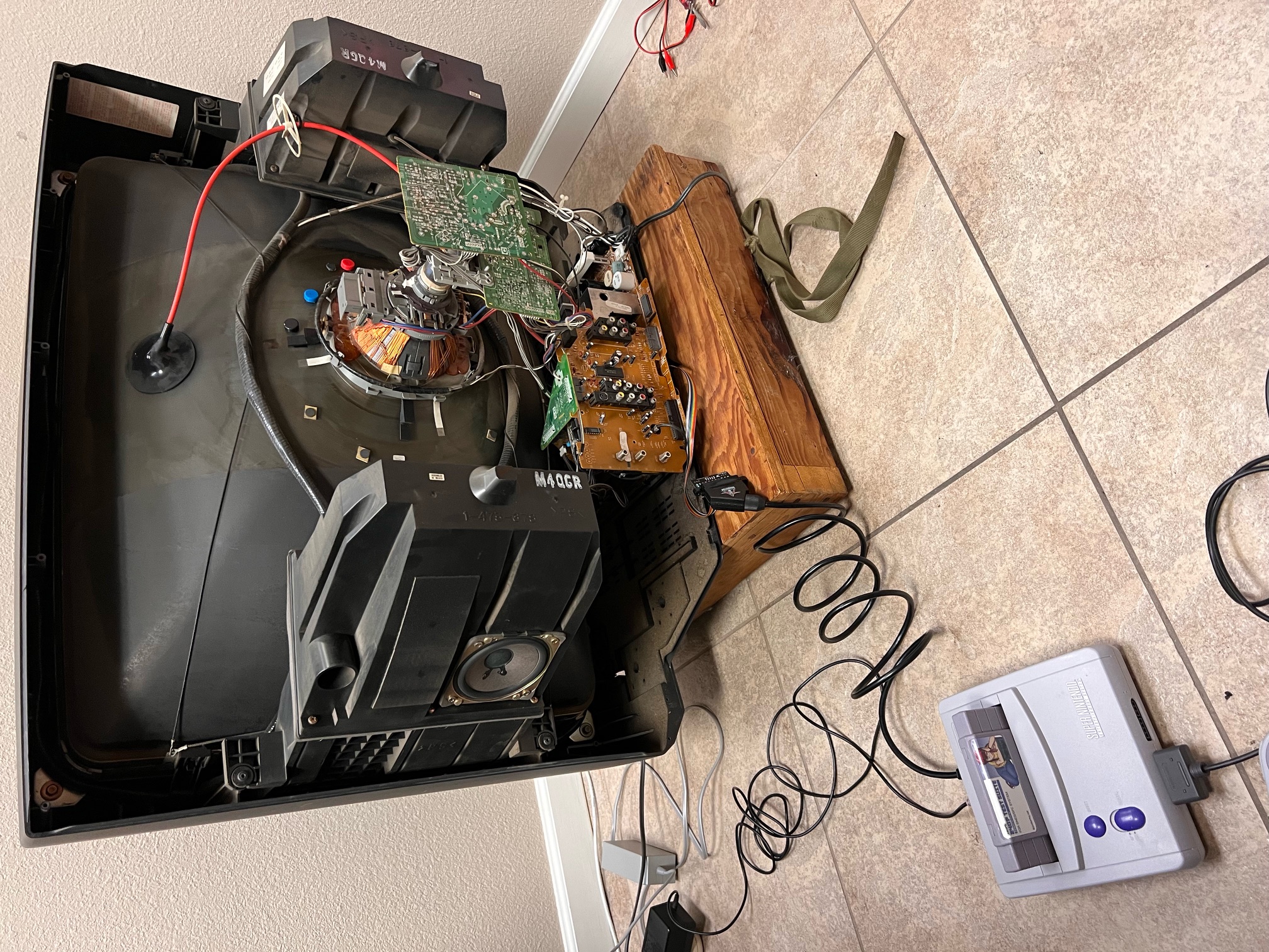
Table of Contents
Contributors
Thank you to everyone who contributed to this guide:
- Sean Burke — contributor, RGB mod and pictures
CRT safety
Caution
You can die doing this! So read carefully! CRT TV is not a toy. Do not open a CRT TV. If you don't have any prior knowledge about handling high voltage devices, this guide is not for you. CRT TV contains high enough voltage (20,000+ V) and current to be deadly, even when it is turned off.
Plan of attack
Manuals and Datasheets
Specs
- Year: 1997
- Format: NTSC
- Chassis: AA-2
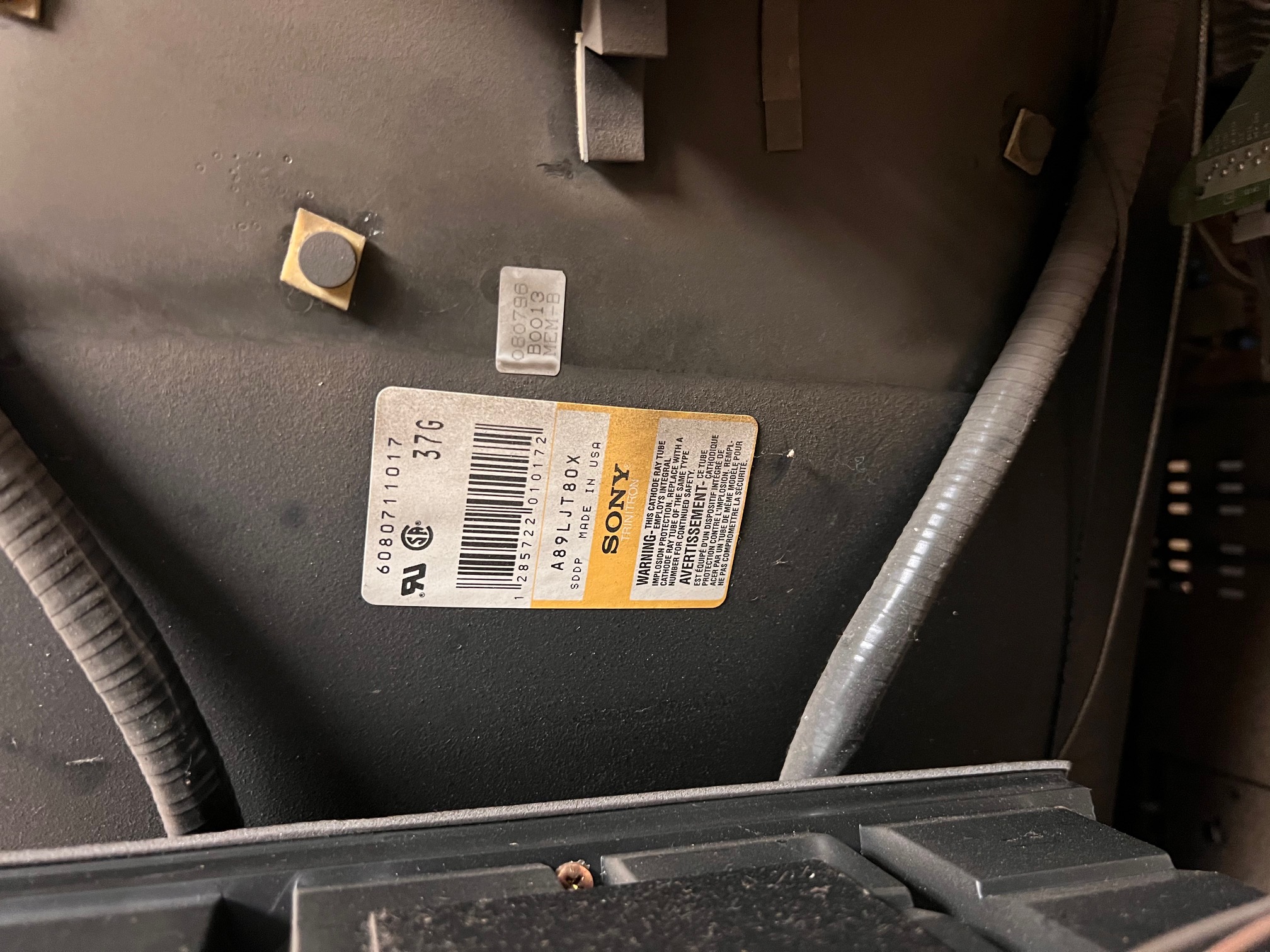
- Tube: Sony Trinitron A89LJT80X
- Jungle Chip: Sony CXA2025AS
- OSD Chip: CXP8564D-004S
- Screen Size: 27"
- Power: 215 W
- Weight: 198 lbs
- Inputs: Composite, RF
RGB mux diagram
Prepare the mux diagram. If you are building your own circuit, this diagram should help.
Performing the mod
STEP 1: Remove the following components
Remove the following resistors
- R1123
- R1128
- R133
Inject R, G, B at the below locations
- R1123 (Red)
- R1128 (Green)
- R133 (Blue)
Below picture shows the resistors that were removed and where we are going to connect the R, G, B and blanking wires. 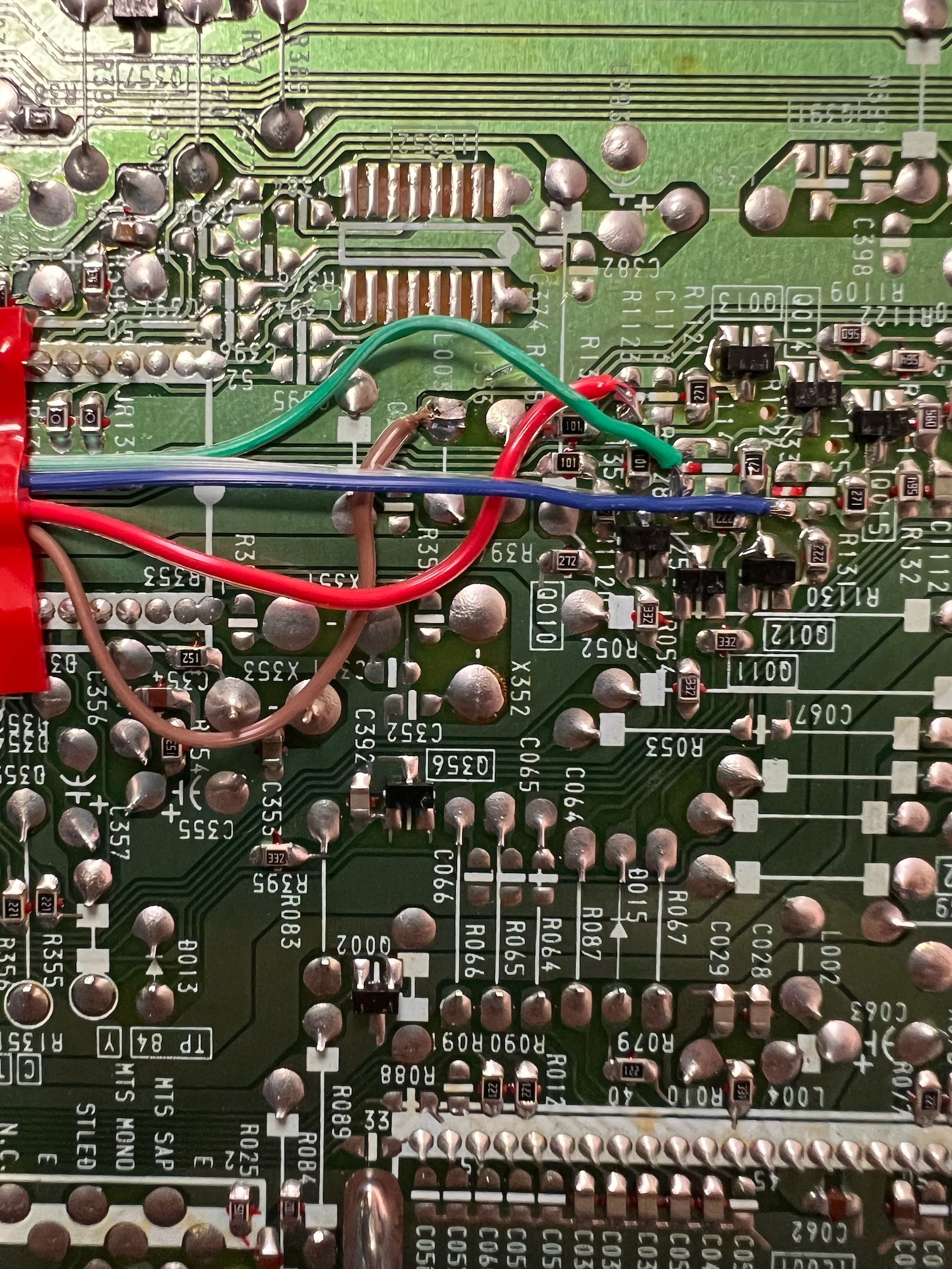
STEP 2: Add a diode to blanking
Blanking diode added. Helps reduce interference. This mod was performed without shielded cables internally and absolutely no interference was noticed.
picture from kv-27s22![]()
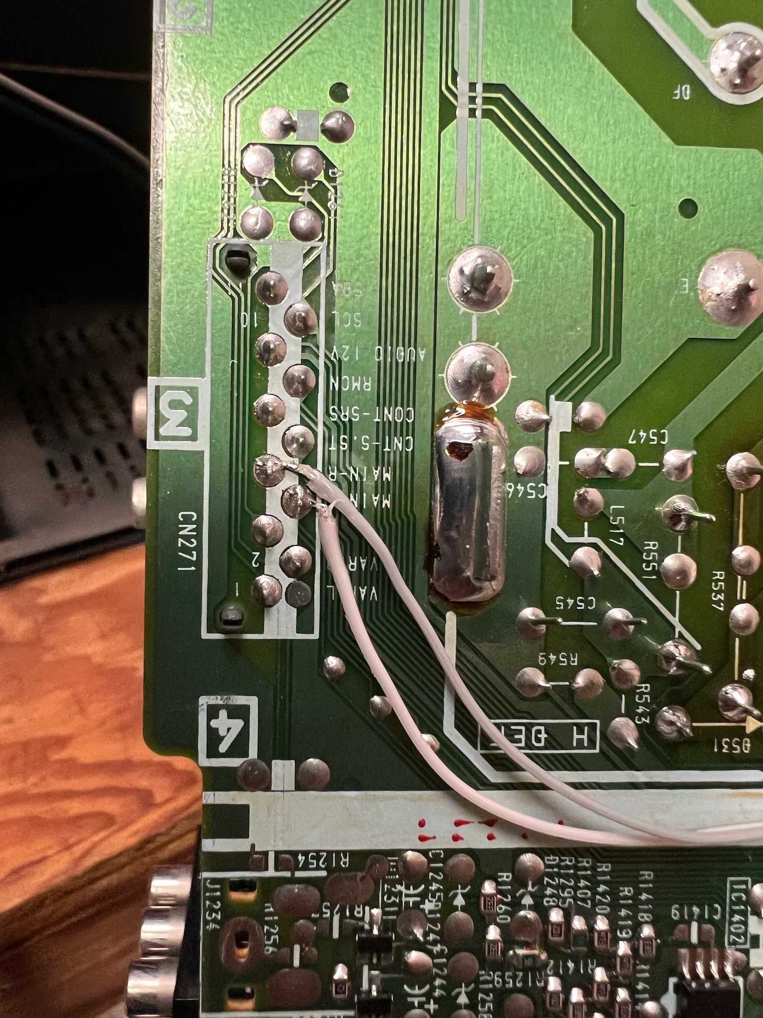
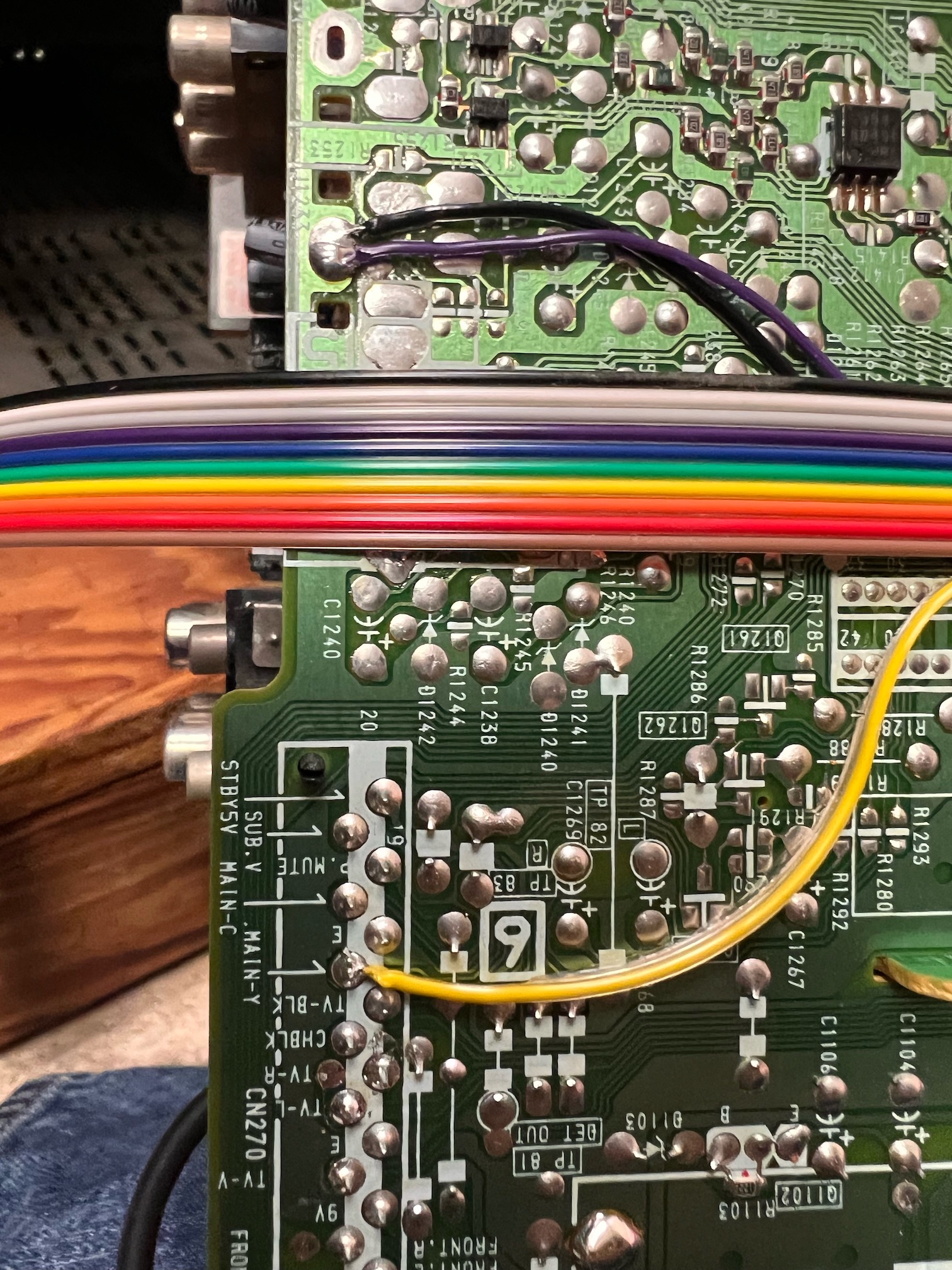
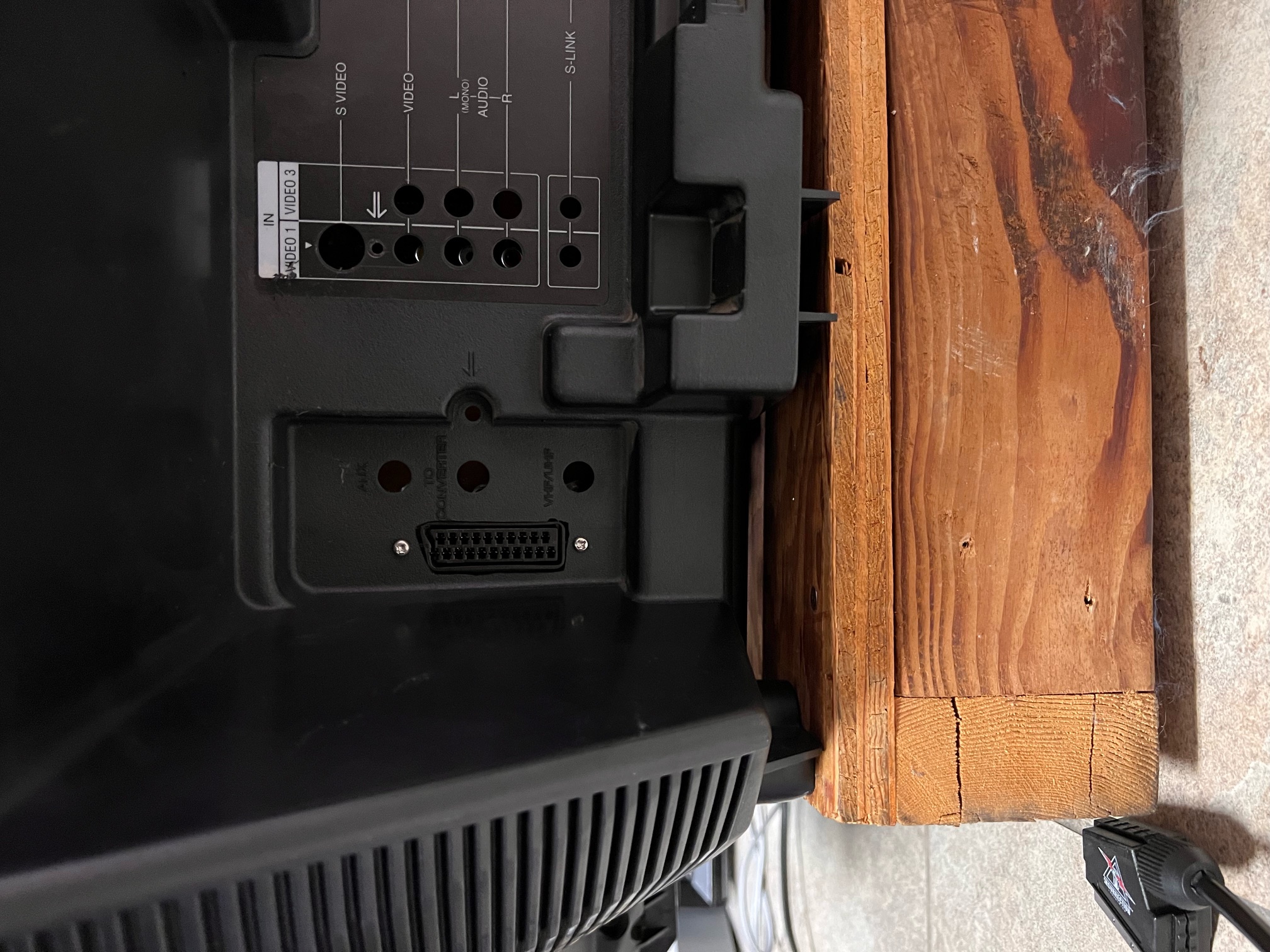
STEP 3: Connect audio and sync wires
Below is slightly different compared to the 27" CRTs that doesn't have a daughter board.
- Ground = Purple/Black wires
- Yellow = Sync
- White = Left Audio
- Grey = Right Audio
Sync is wired to Main-Y on CN270, and audio is wired to Main-L and Main-R on CN271.
STEP 4: Build your mux circuit
This mod uses the RGB mux board. This is optional, but will make your mod easier and stable. You can also create the circuit presented in the schematics above without the board. Please also checkout the mux calculator to play with your own values.
| On Sony CRT Chassis | KV-35V35 |
|---|---|
| CRT RGB inline resistor | 2.2kΩ |
| CRT RGB ground resistors removed | 390Ω |
| 0.1μF caps replaced | No |
| Add diodes on chassis RGB lines? | No |
| Add blanking diode on chassis | Yes |
| RGB mux board | KV-35V35 |
|---|---|
| Mux board RGB termination (R1, R2, R3) | 75Ω |
| Mux board RGB inline resistors (R4, R5, R6) | 330Ω |
| Mux board Audio LR (R7, R8) | 1kΩ |
| Mux board blanking diode (R9) | 1N4148 |
| Mux board blanking ground resistor (R10) | 330Ω |
| Mux board blanking resistor (R11) | 470Ω |
Compatible mux boards:
It is important to note that the blanking ground resistor (R10) is necessary to prevent strange black backgrounds from appearing on the KV-27S22 OSD text.
Step 5: Attach the female SCART connector to TV
Creating a SCART cutout and mounting it is an art. I have a dedicated section for it. How to create and mount a SCART female plug?
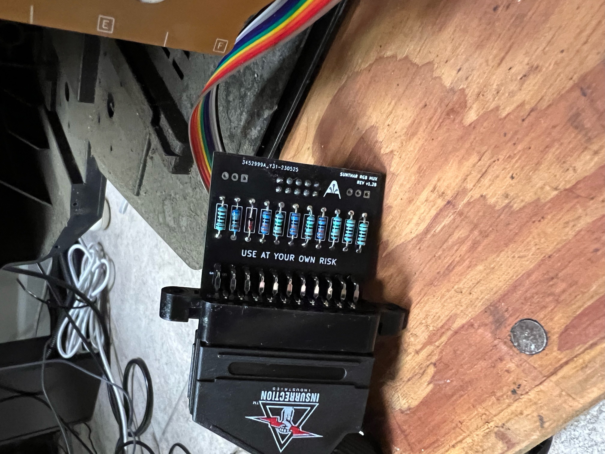
Perfect clearance with the v1.2B mini RGB mux board ![]()
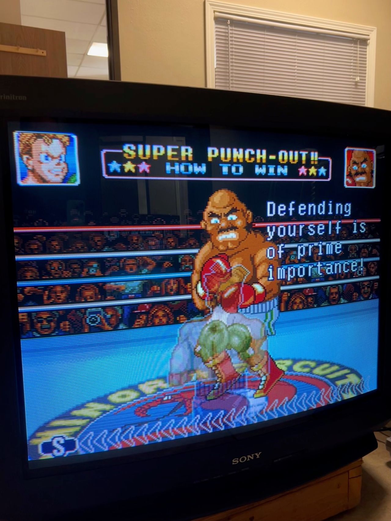
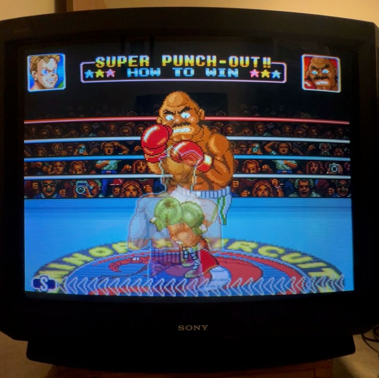
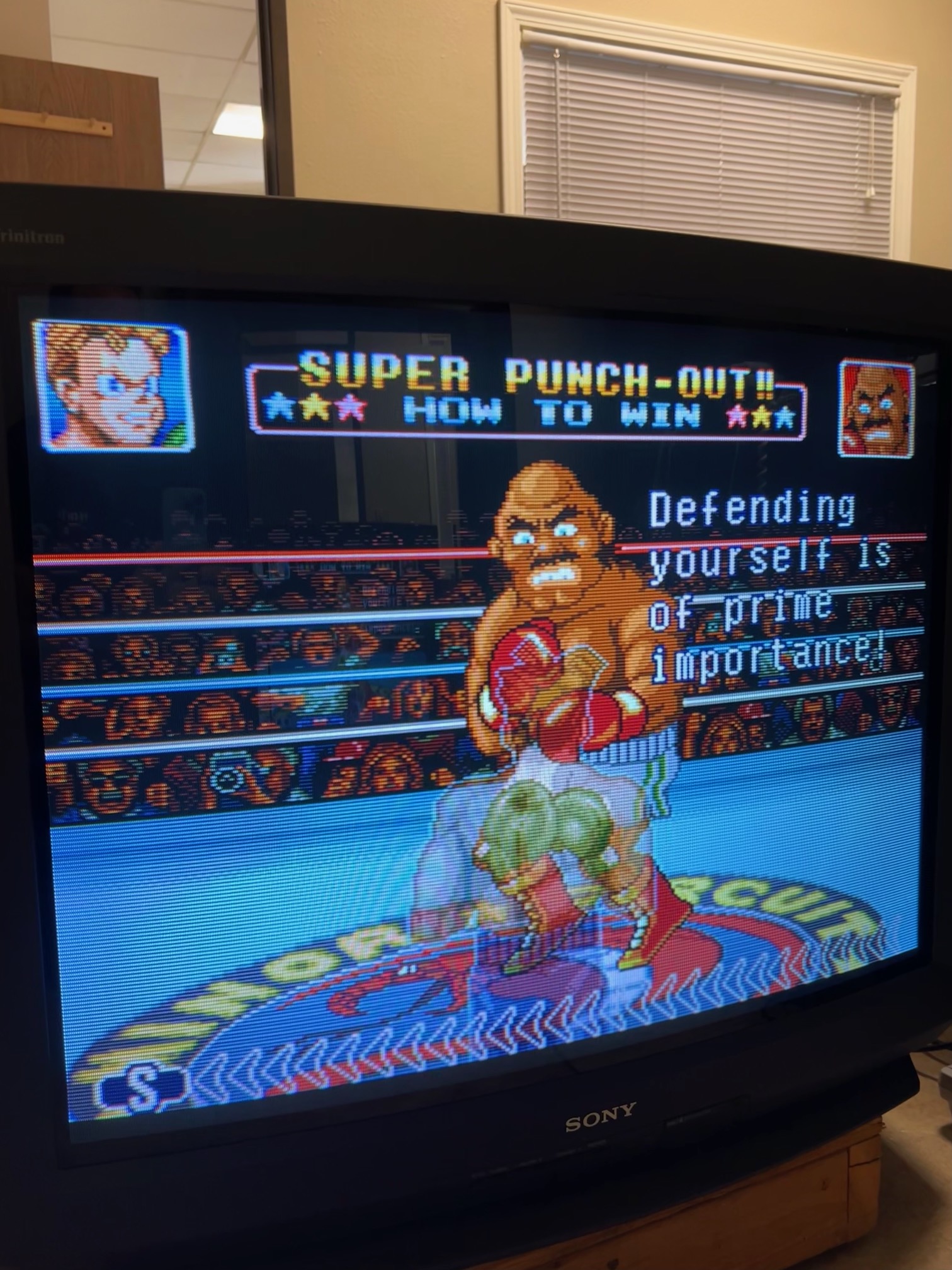
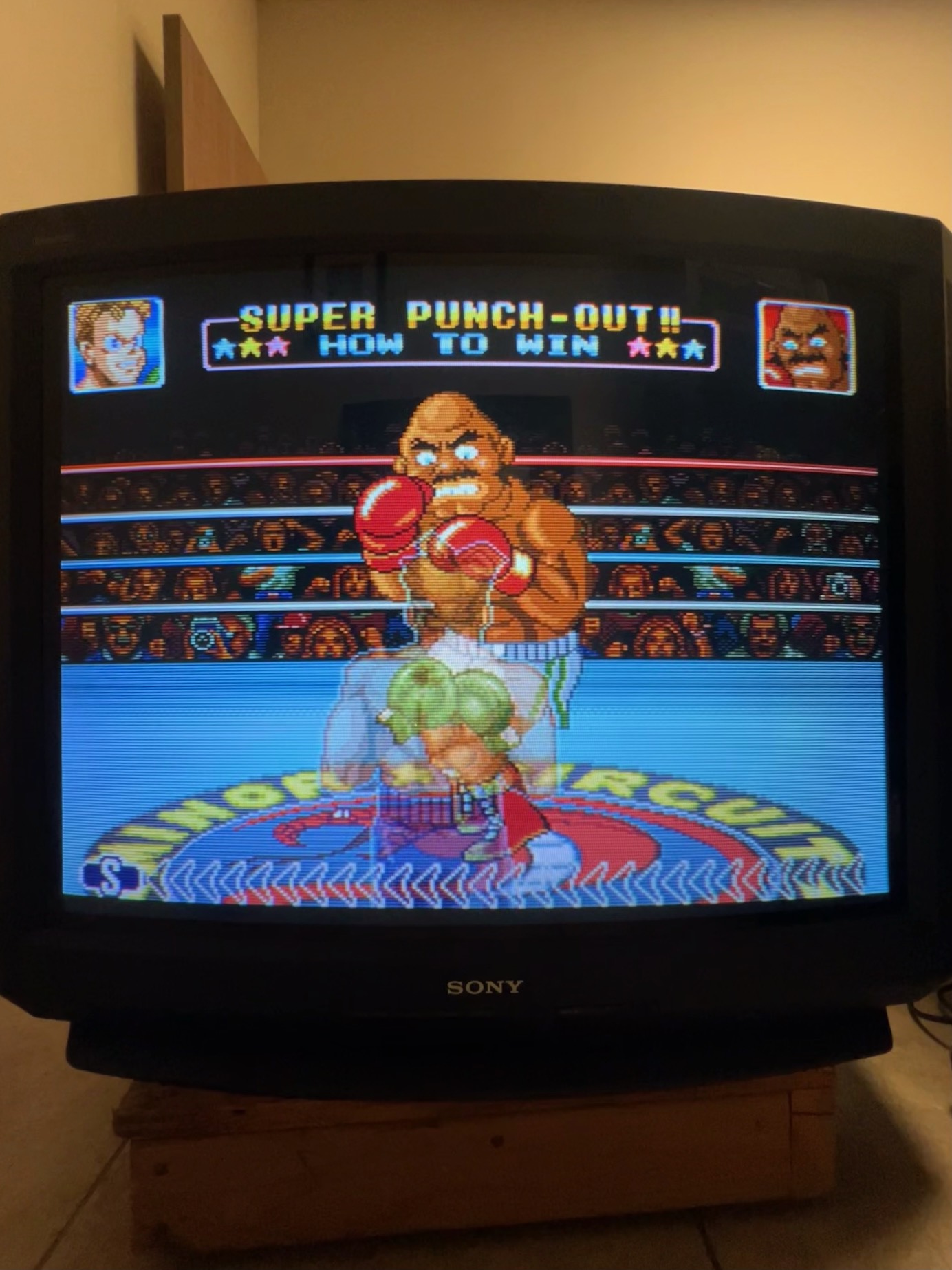
Games
Set
Pictures
Reference Photos