
Sony (BA-5) KV-32FS13
Sony (BA-5) KV-32FS13 CRT RGB mod
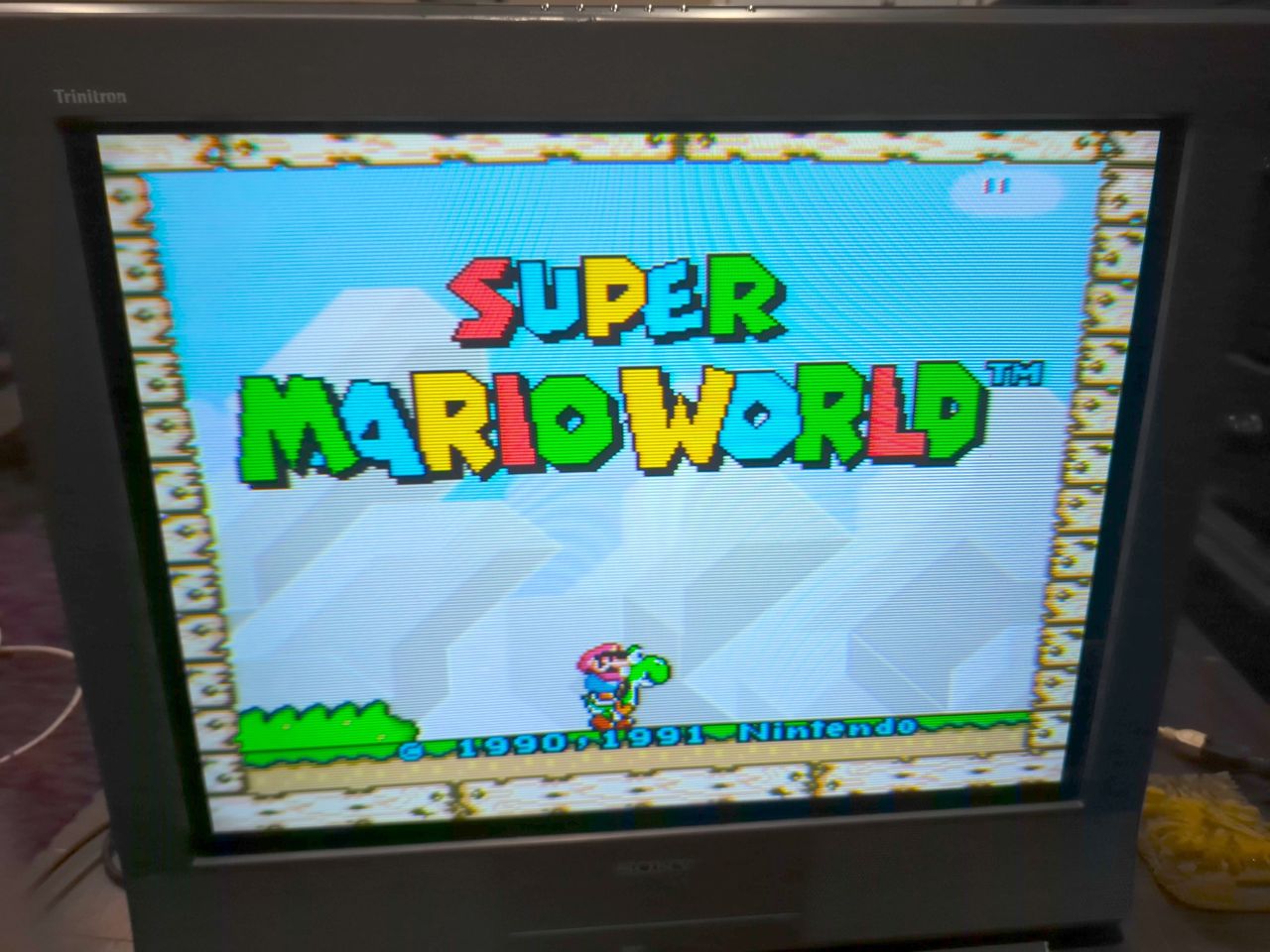
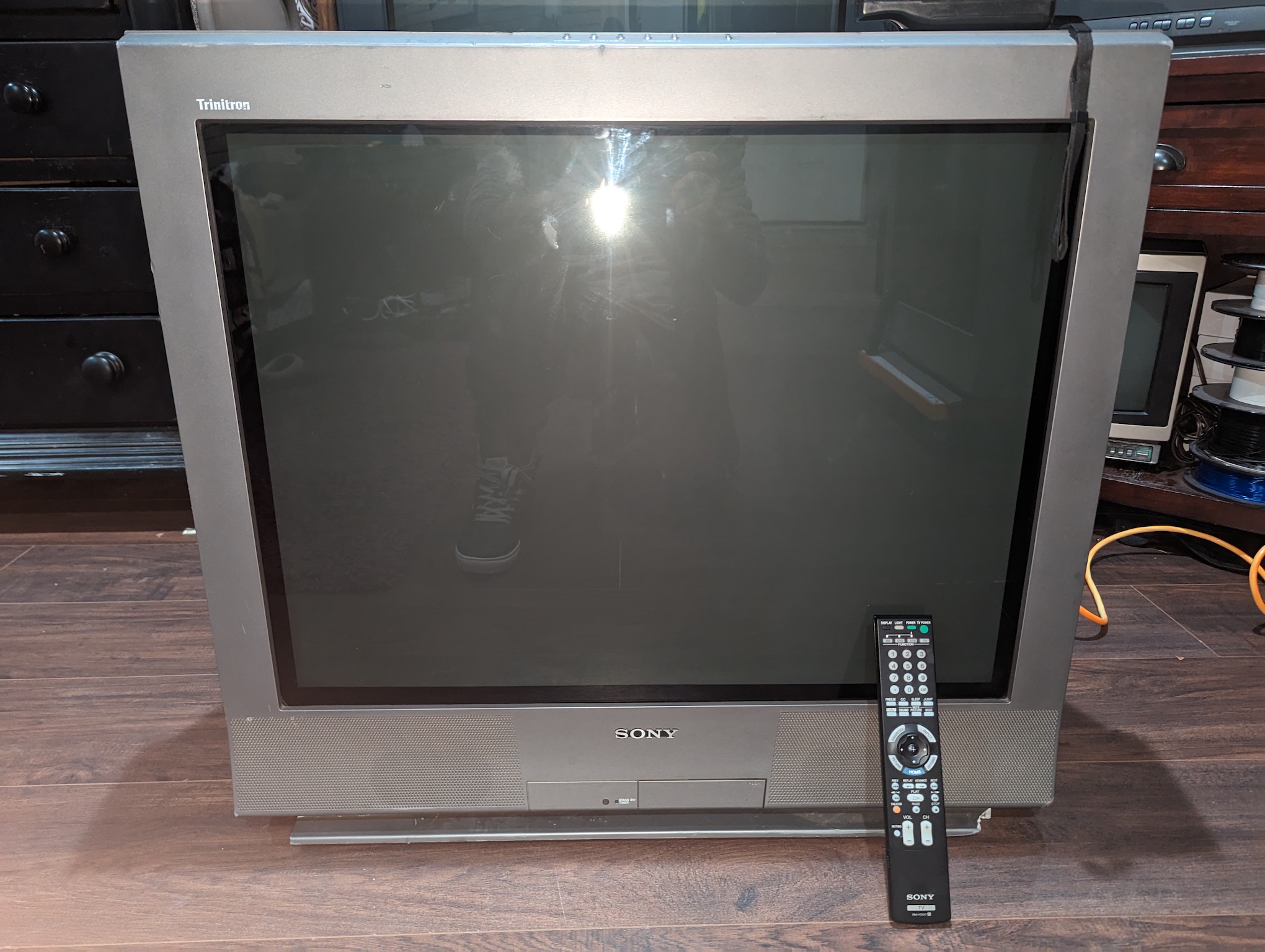
The Sony KV-32FS13 is a 32" FD Trinitron WEGA CRT television. Renowned for its flat-screen aperture grille technology, it delivers vivid colors and sharp pictures.
This set is RGB moddable.
View full CRT details and more mod examples →
This guide should also work for the below models:
- KV-32FS13
- KV-32FS17
- KV-34FS17
Table of Contents
Contributors
Thank you to everyone who contributed to this guide:
- manadream — showcase author
- Mike Morisette — contributor, CRT specs from CRT Database.
- CyTsune — contributor, RGB mod and pictures
CRT safety
Caution
You can die doing this! So read carefully! CRT TV is not a toy. Do not open a CRT TV. If you don't have any prior knowledge about handling high voltage devices, this guide is not for you. CRT TV contains high enough voltage (20,000+ V) and current to be deadly, even when it is turned off.
Plan of attack
Manuals and Datasheets
Specs
- Manufactured: Mexico (2001)
- Format: NTSC
- Chassis: BA-5
- Tube: Sony FD Trinitron A80LPD50X
- Jungle Chip: Sony CXA2154AS
- OSD Chip: M372280MK-114SP
- Screen Size: 32"
- Power: 195 W
- Weight: 163 lbs
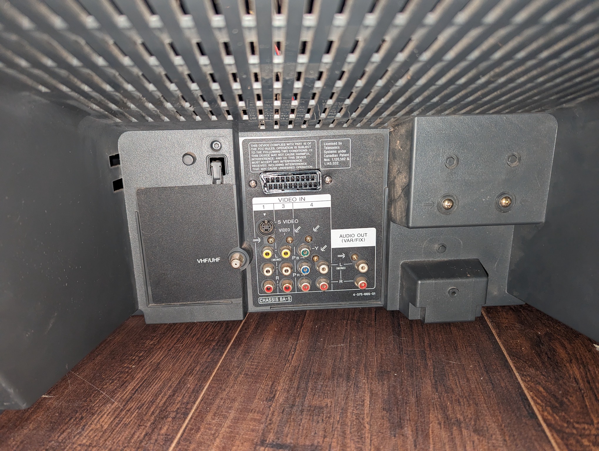
- Inputs: Composite, S-Video, RF, Component YPbPr
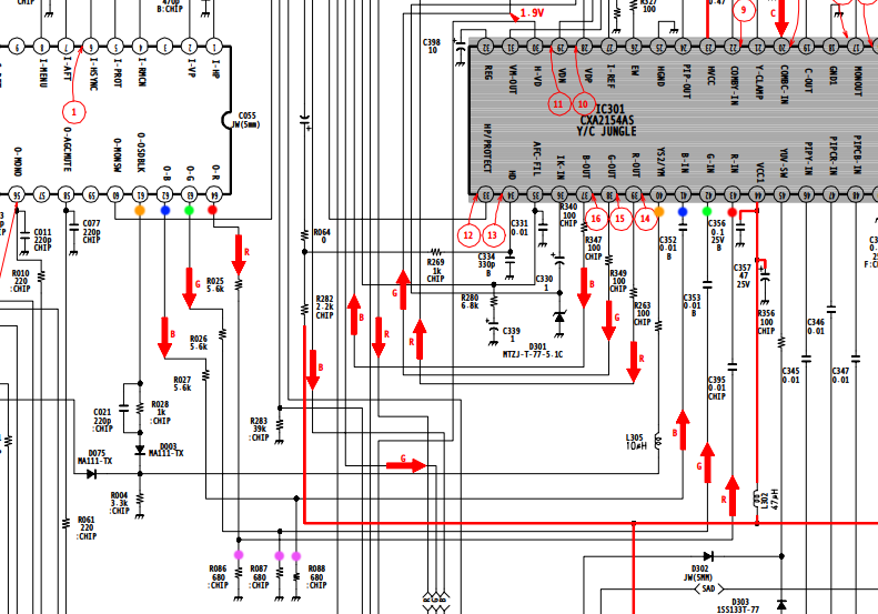
Schematics
Calculating the RGB external resistor value
Formula from our theory page!

RGB external resistor value = 0.7 x (6800 + 75) - (75 x 5) / (5 - 0.7) = (4812 - 375) / 4.3 = 1030 ohm
~ 1 Kohm resistors should do the job.
RGB mux diagram
Prepare the mux diagram. If you are building your own circuit, this diagram should help.
Performing the mod
Now that you roughly know what needs to be done, prepare for the mod. Place the board on a comfortable place. Make sure you are not putting pressure on the flyback or other components.
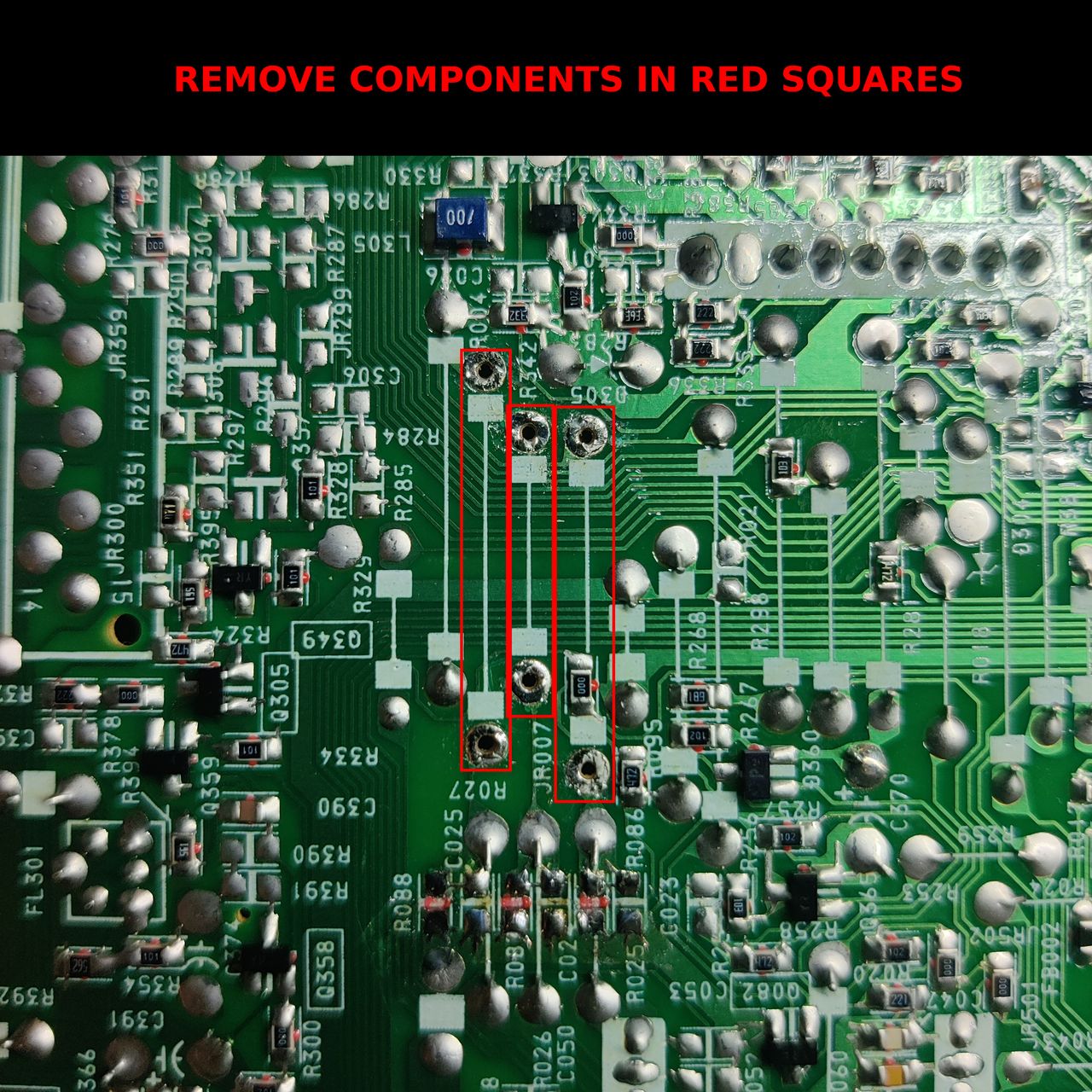
STEP 1: Remove the following components
Most of the mod will happen on the MA board. 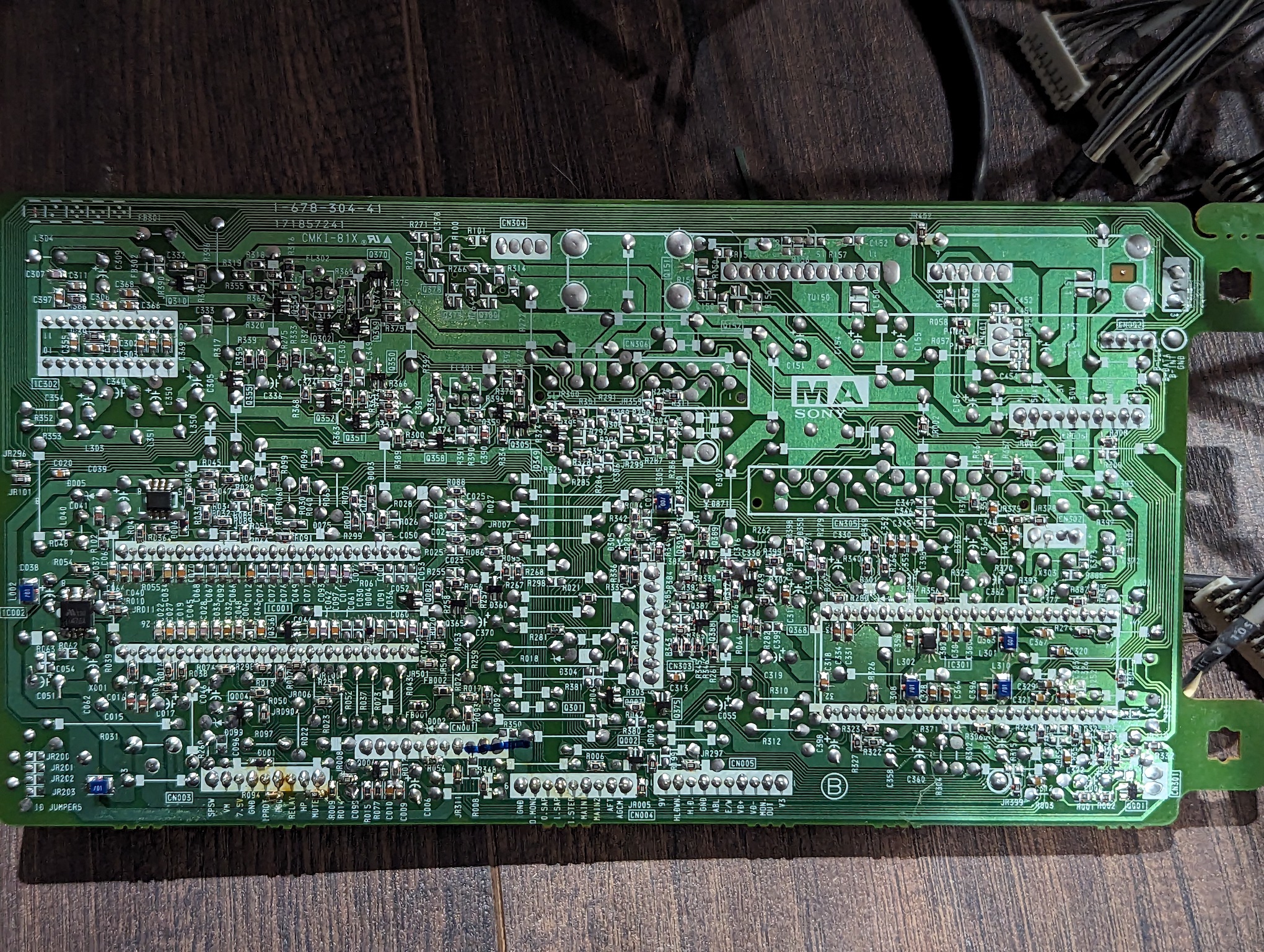
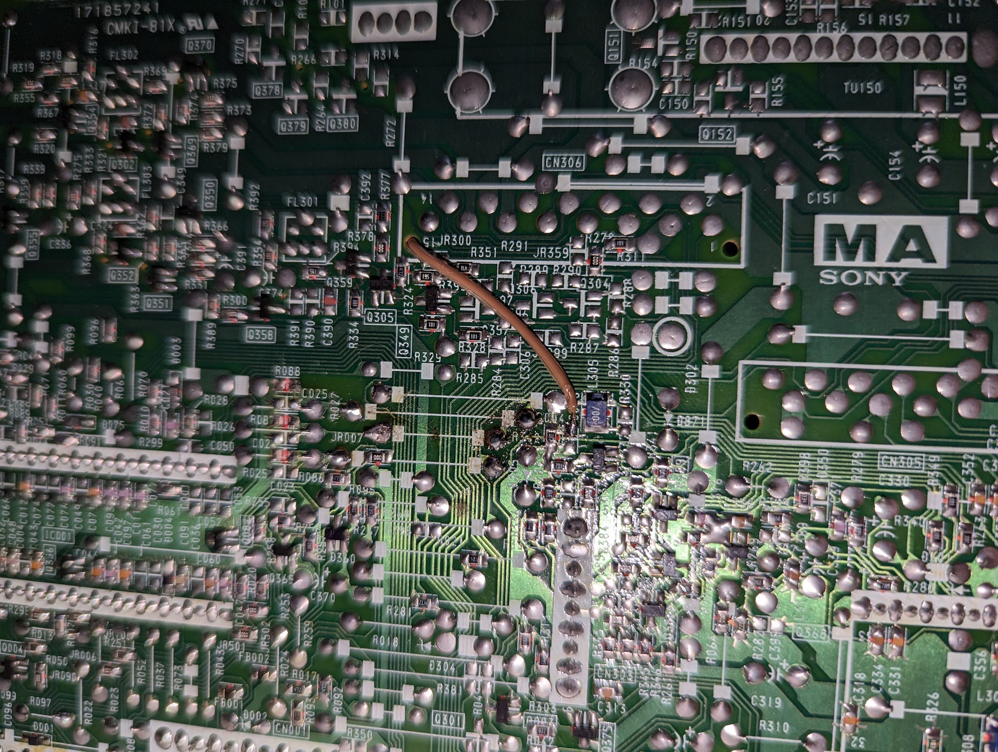
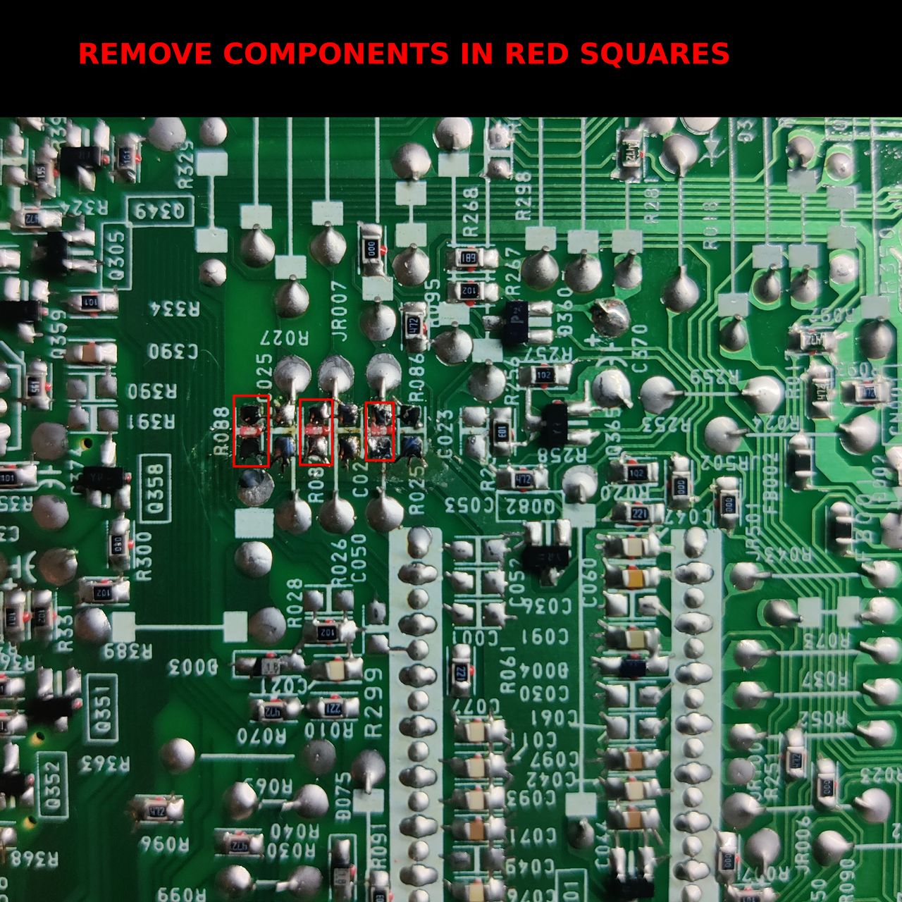
Remove the following components. RGB resistors to the ground. Measure twice and mark before you remove.
- R086 (680Ω)
- R087 (680Ω)
- R088 (680Ω)
Note: there can be slight differences in the board layout depending on the CRT revision.
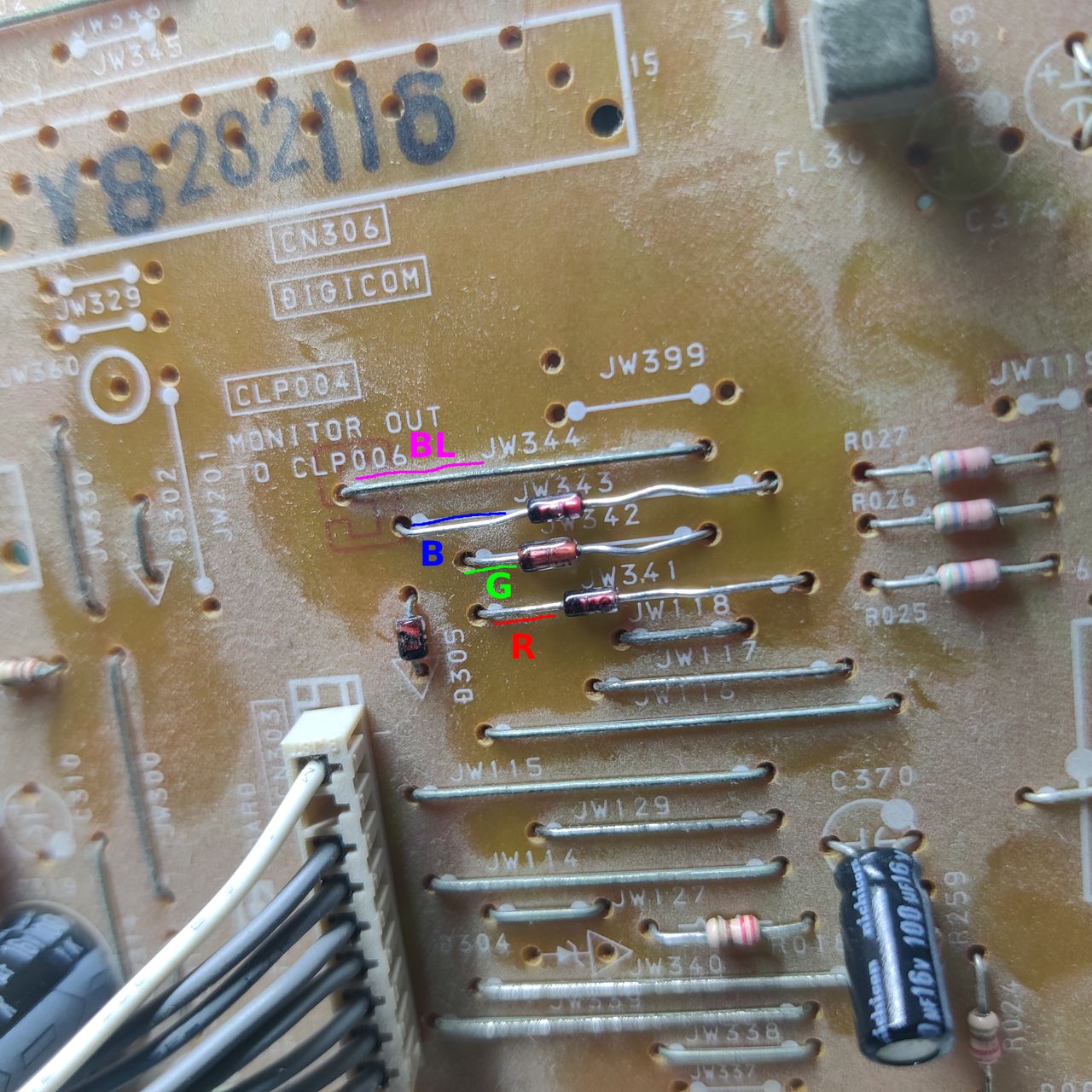
STEP 2: Connect RGBs, Blanking and Audio
See picture above to see where blanking should be connected.
Let's remove the jumpers JW343, JW343, JW341 and replace with 3 1N4148 diodes. Pay attention to the direction of the diodes. There is a black bar indicating which way the current flows. This helps reduce feedback noise and voltage going back into the OSD.
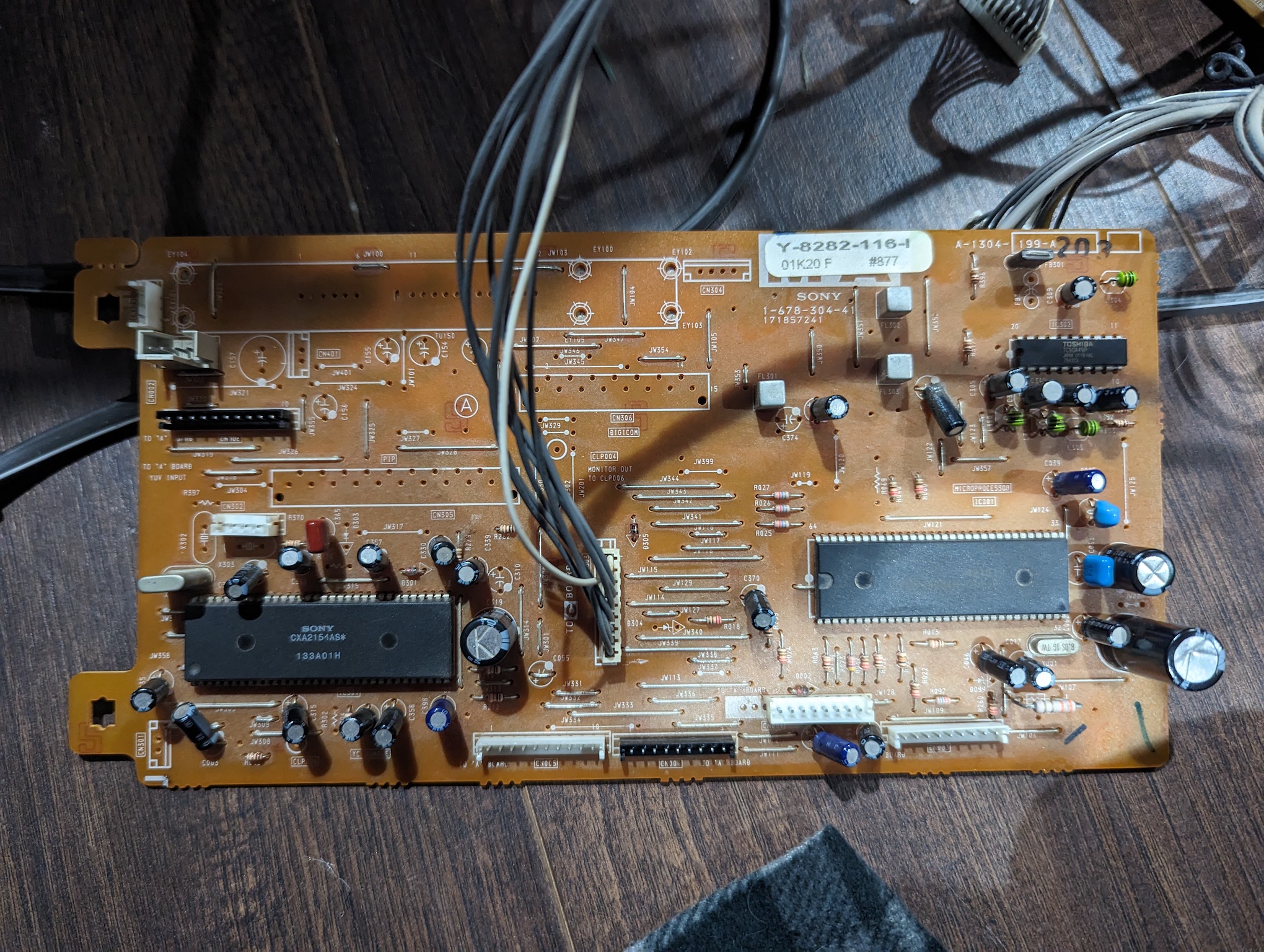
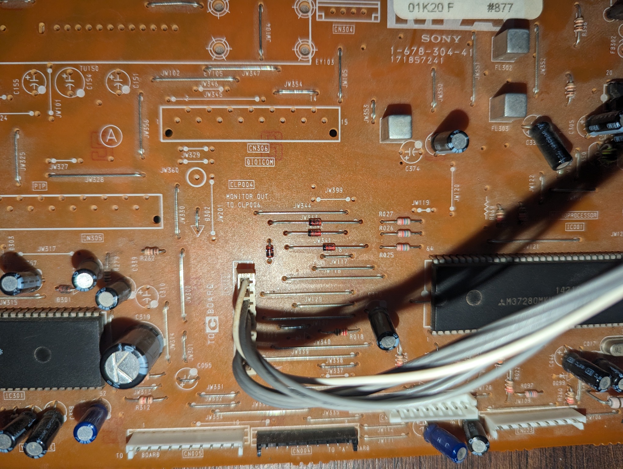
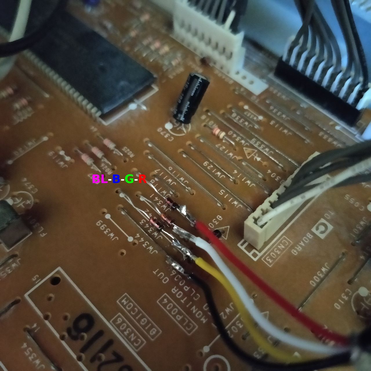
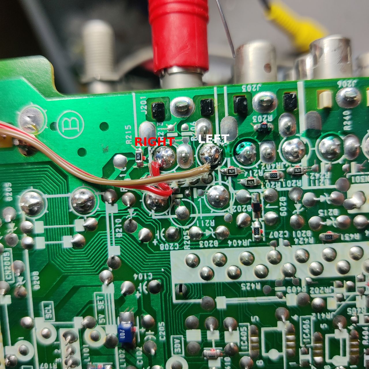
Then attach the R, G, B wires to the respective legs of the diodes. Wires should be attached to the side closer to the jungle chip.
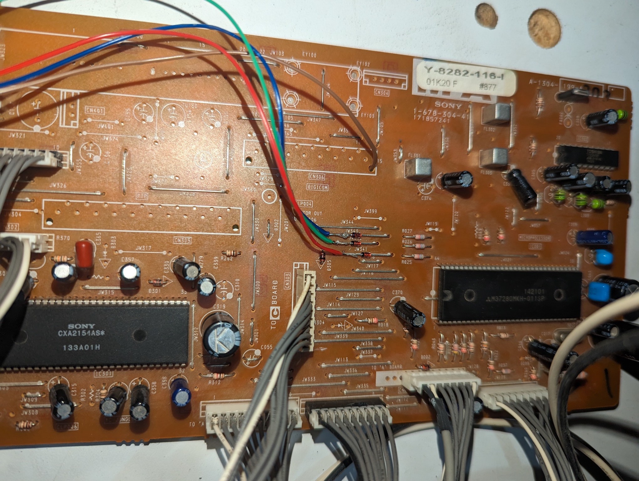
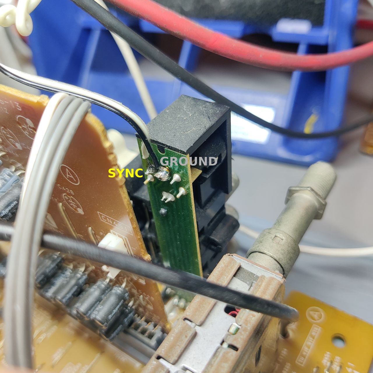
Blanking wire should be attached as seen on the picture below.
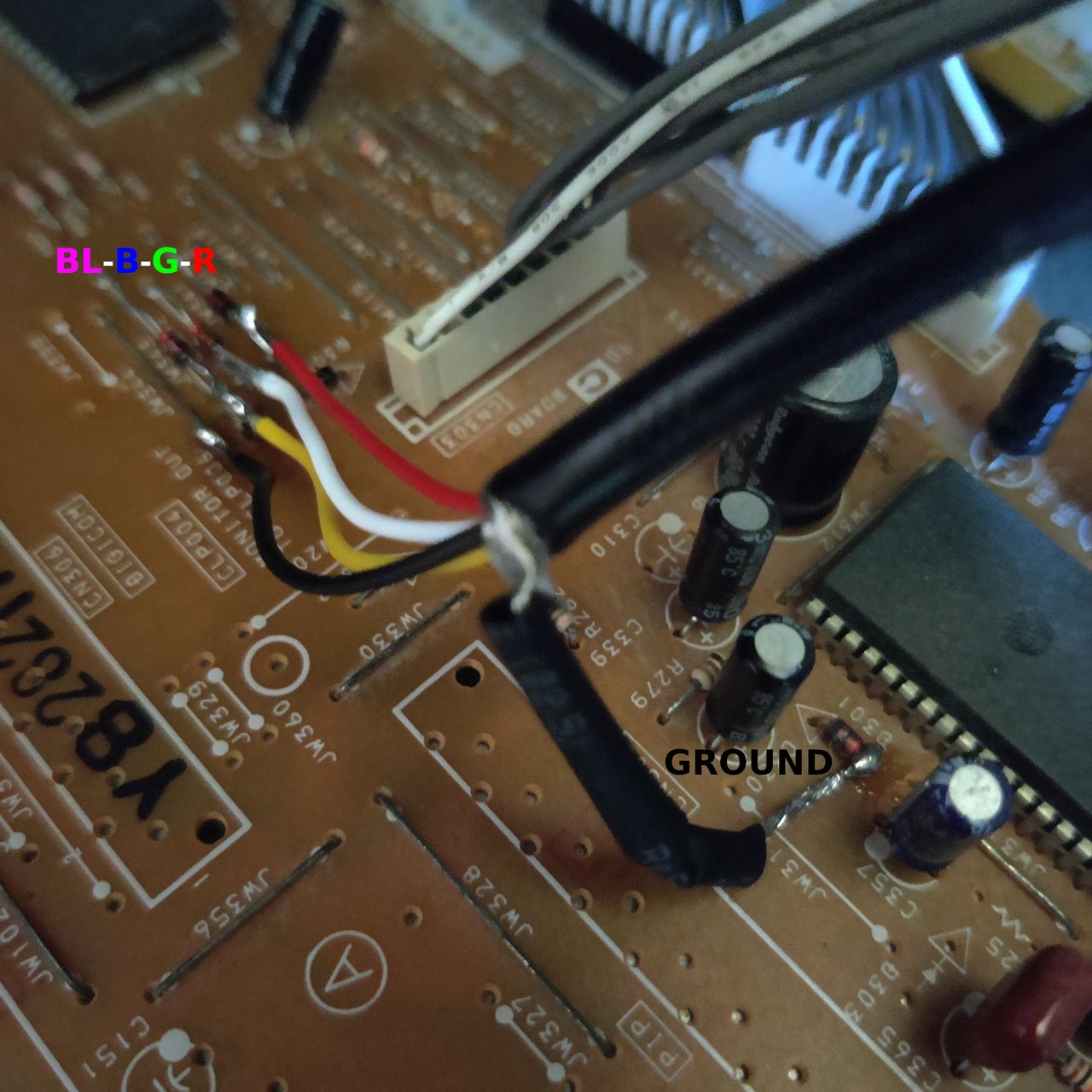
Sync wire (yellow) should be connected directly to the s-video Y pin. Ground wire (purple) should be connected to the ground.
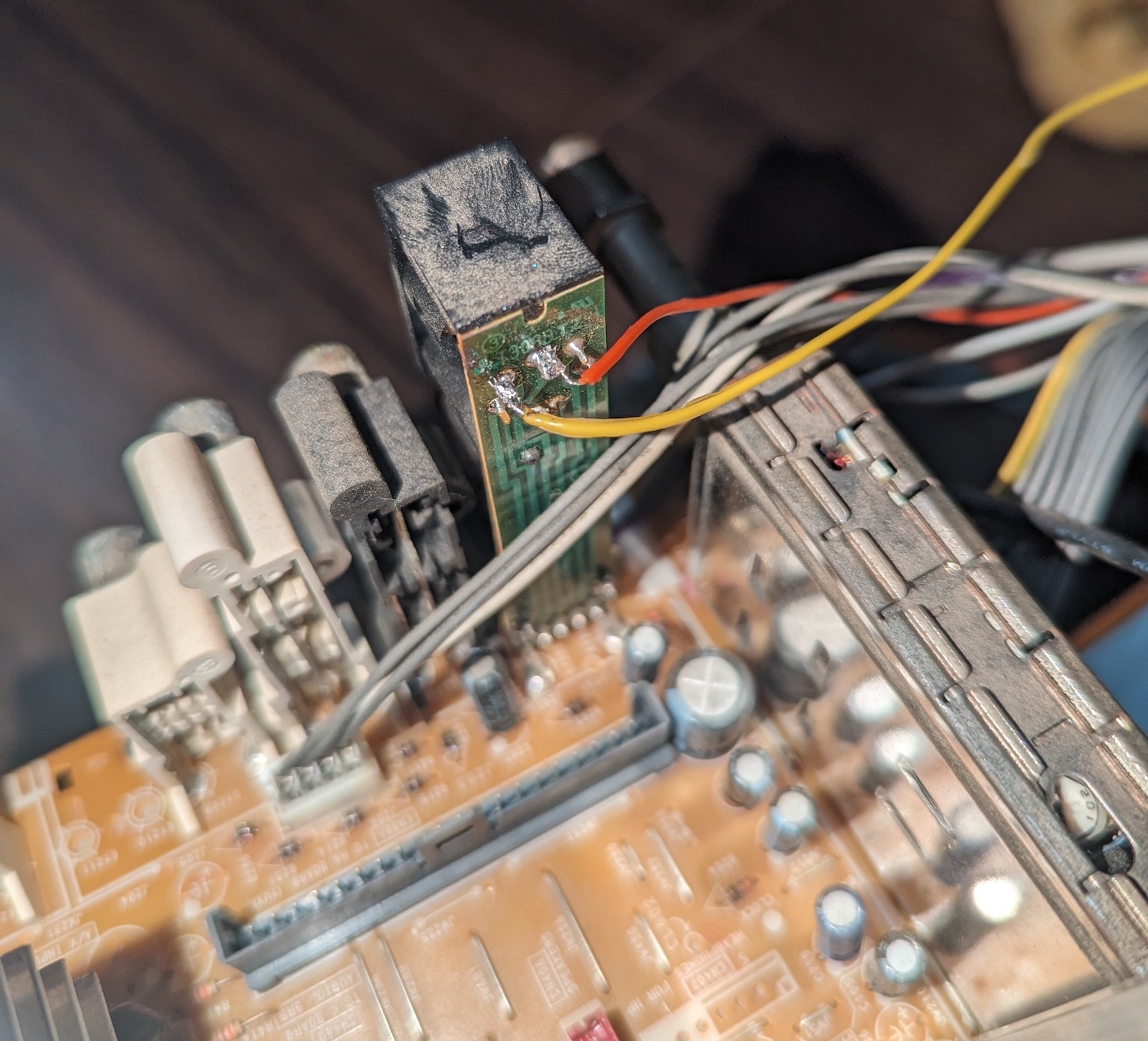
Black wire is for ground. Orange and purple wires are auxillary wires, you can connect them to ground or leave them floating.
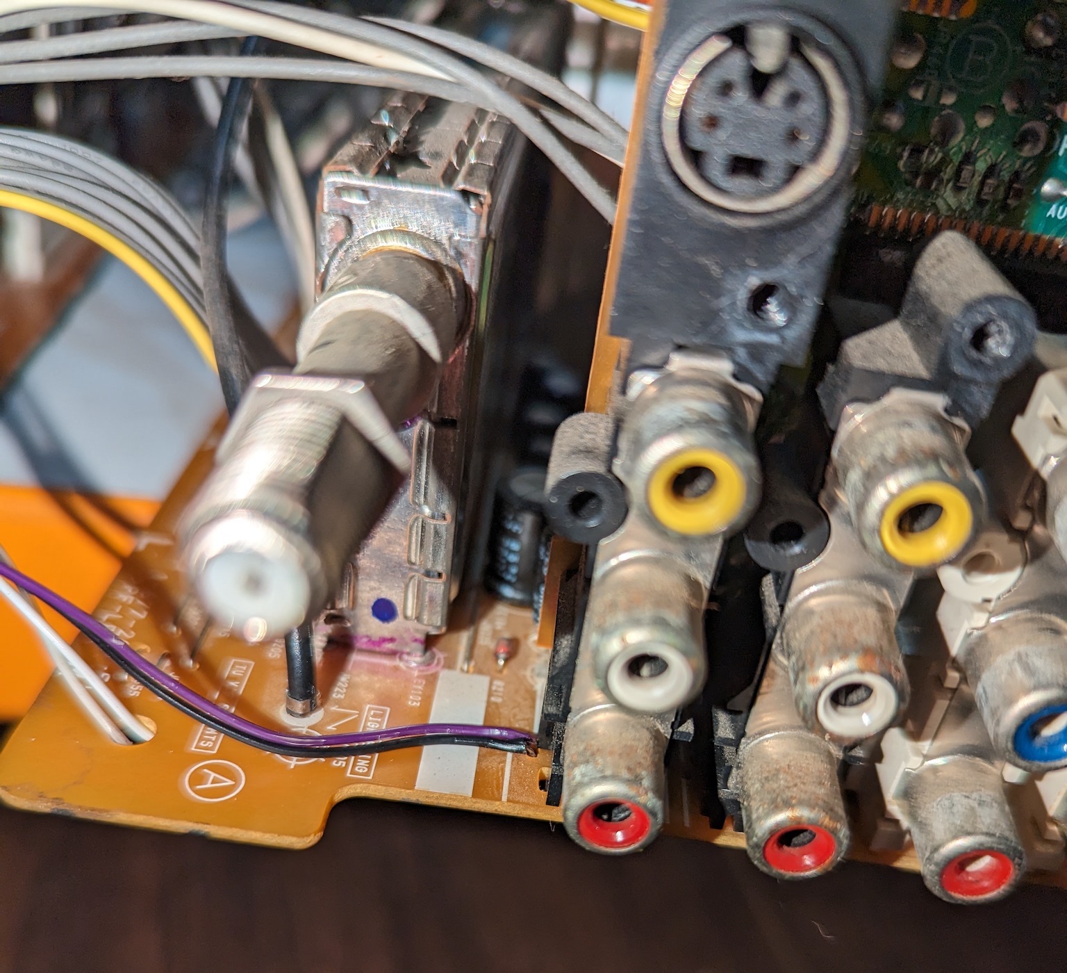
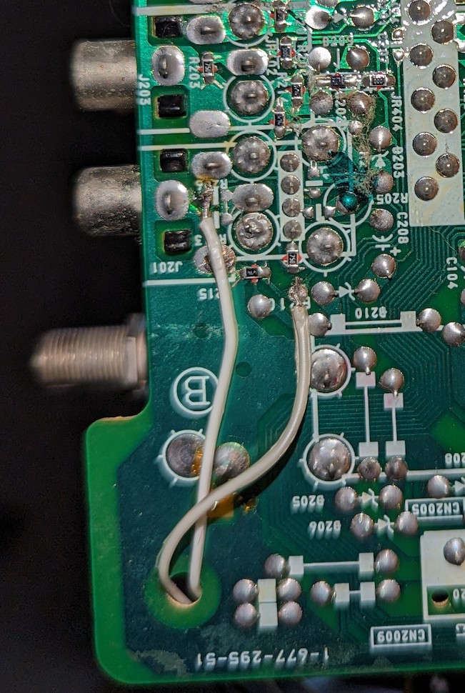
Audio wiring can go below the board. Connect audio left (white) and audio right (grey) as seen in the pics below.
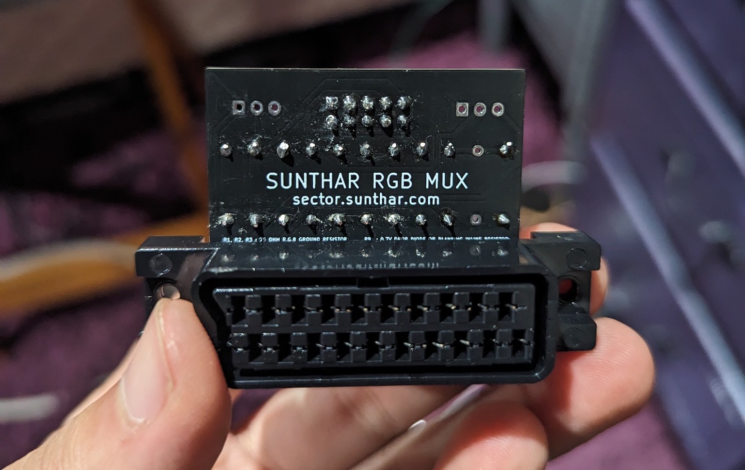
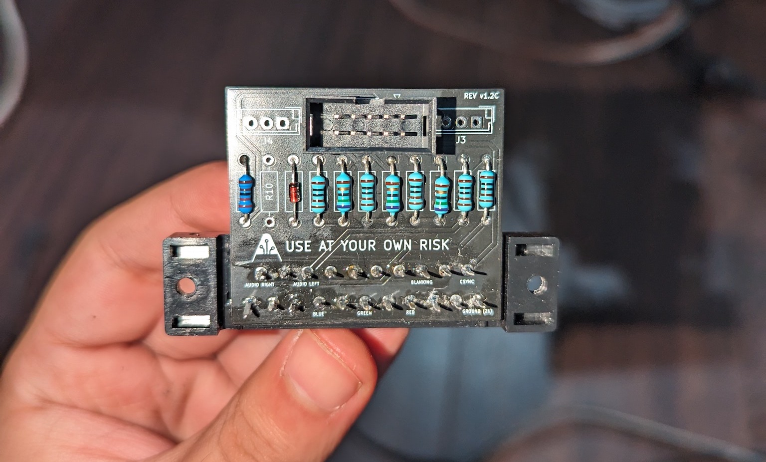
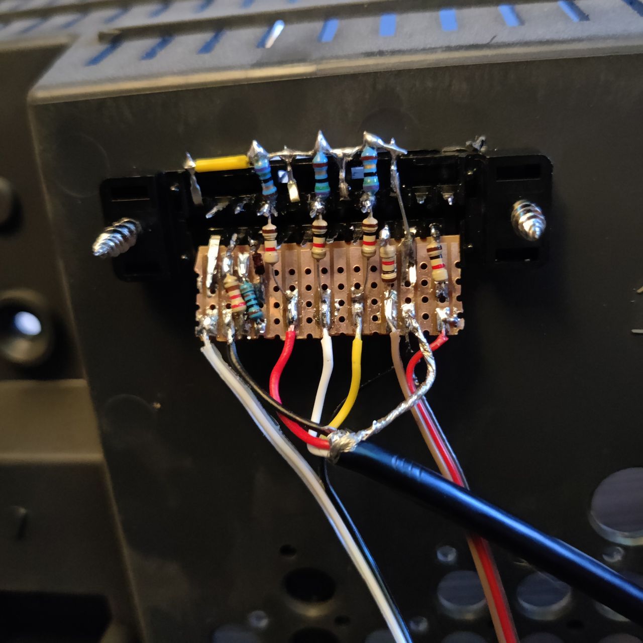
STEP 3: Build your mux board
This mod uses the RGB mux board. This is optional, but will make your mod easier and stable. You can also create the circuit presented in the schematics above without the board. Please also checkout the mux calculator to play with your own values.
| On Sony CRT Chassis | KV-32FS13 |
|---|---|
| CRT RGB inline resistor | 6.8kΩ |
| CRT RGB ground resistors removed | 680Ω |
| 0.1μF caps replaced | No |
| Add diodes on chassis RGB lines? | Yes |
| Add blanking diode on chassis | No |
| RGB mux board | KV-32FS13 |
|---|---|
| Mux board RGB termination (R1, R2, R3) | 75Ω |
| Mux board RGB inline resistors (R4, R5, R6) | 1kΩ |
| Mux board Audio LR (R7, R8) | 1kΩ |
| Mux board blanking diode (R9) | 1N4148 |
| Mux board blanking ground resistor (R10) | open |
| Mux board blanking resistor (R11) | 1.2kΩ |
| Mux board transistor base resistor (R12) | 1kΩ |
| Mux board transistor (Q1) | PN2222A |
Compatible mux boards:
You have to be strategic about the board placement. Sony KV-20FV12 has tight spacing with flyback and the audio board on the way.
It is recommended to use the Rev C mini board for this CRT with the straight SCART connector. Rev B board can be used, if the spacing is carefully planned.
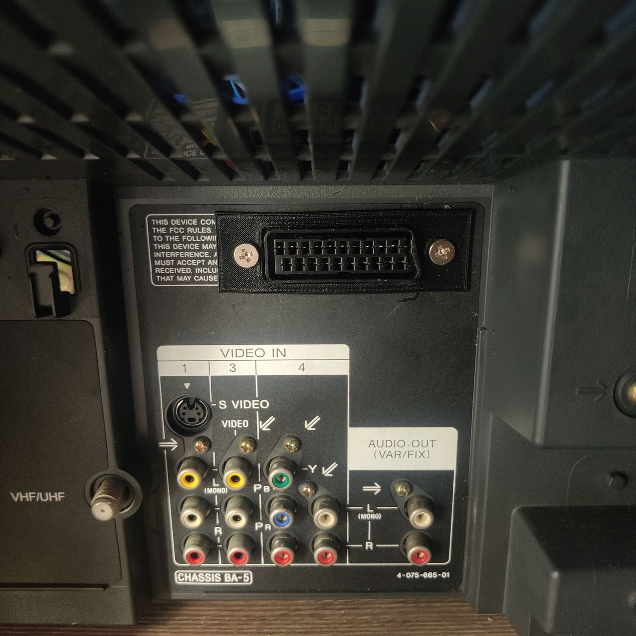
STEP 4: Attach the female SCART connector to TV
Creating a SCART cutout and mounting it is an art. I have a dedicated section for it.
How to create and mount a SCART female plug?
Getting into the service menu
- Turn the set on and then put into standby
- Press the
Display,5,VOL +buttons in sequence - Turn on the CRT and you should be in service mode
- Use buttons "1" and "4" on the remote control to navigate the service menu
- Use buttons "3" and "6" to adjust the selected data
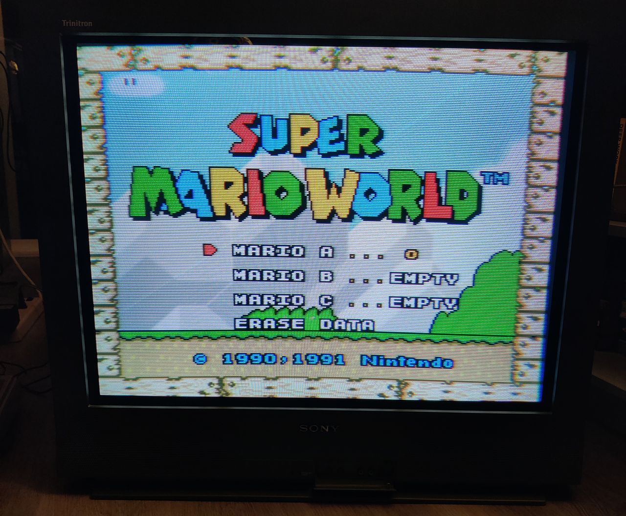
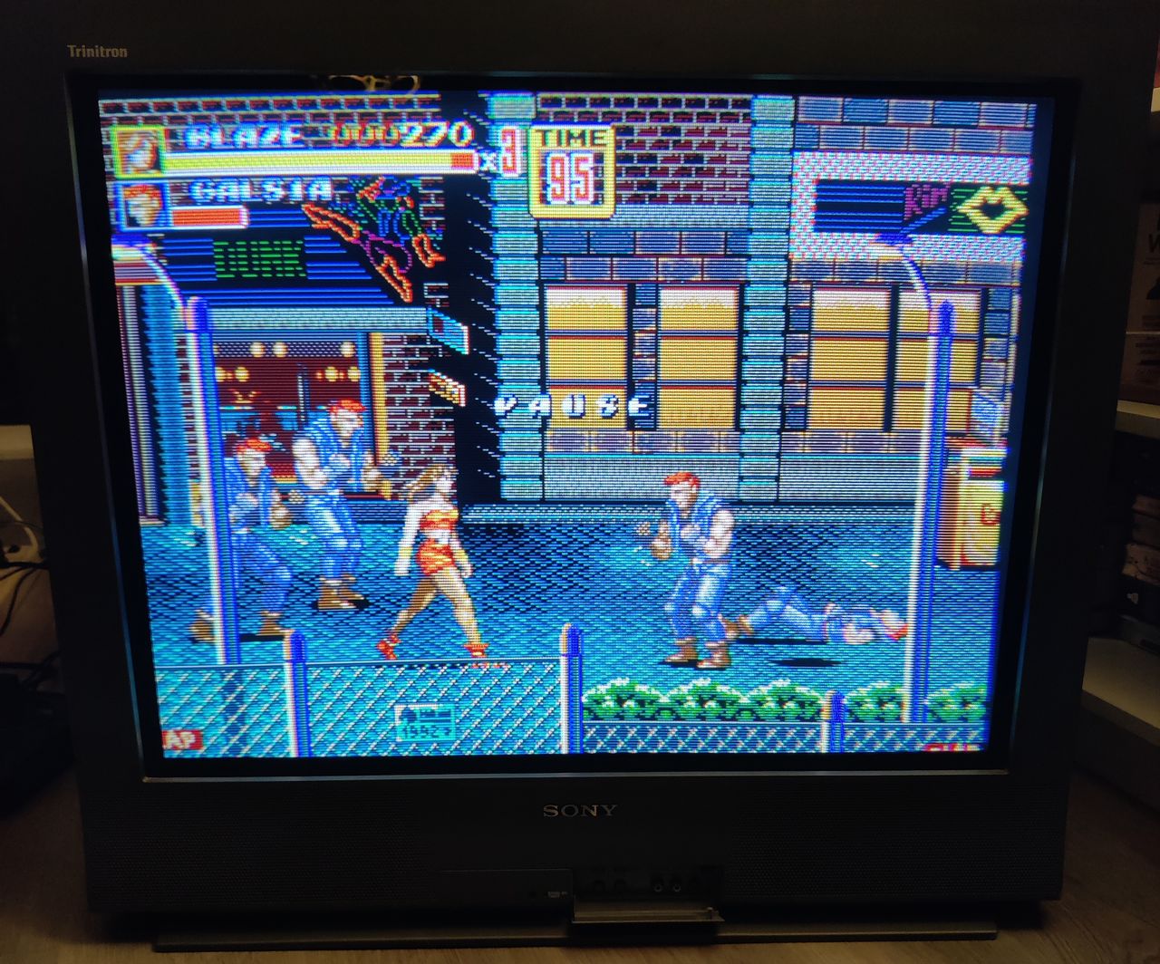
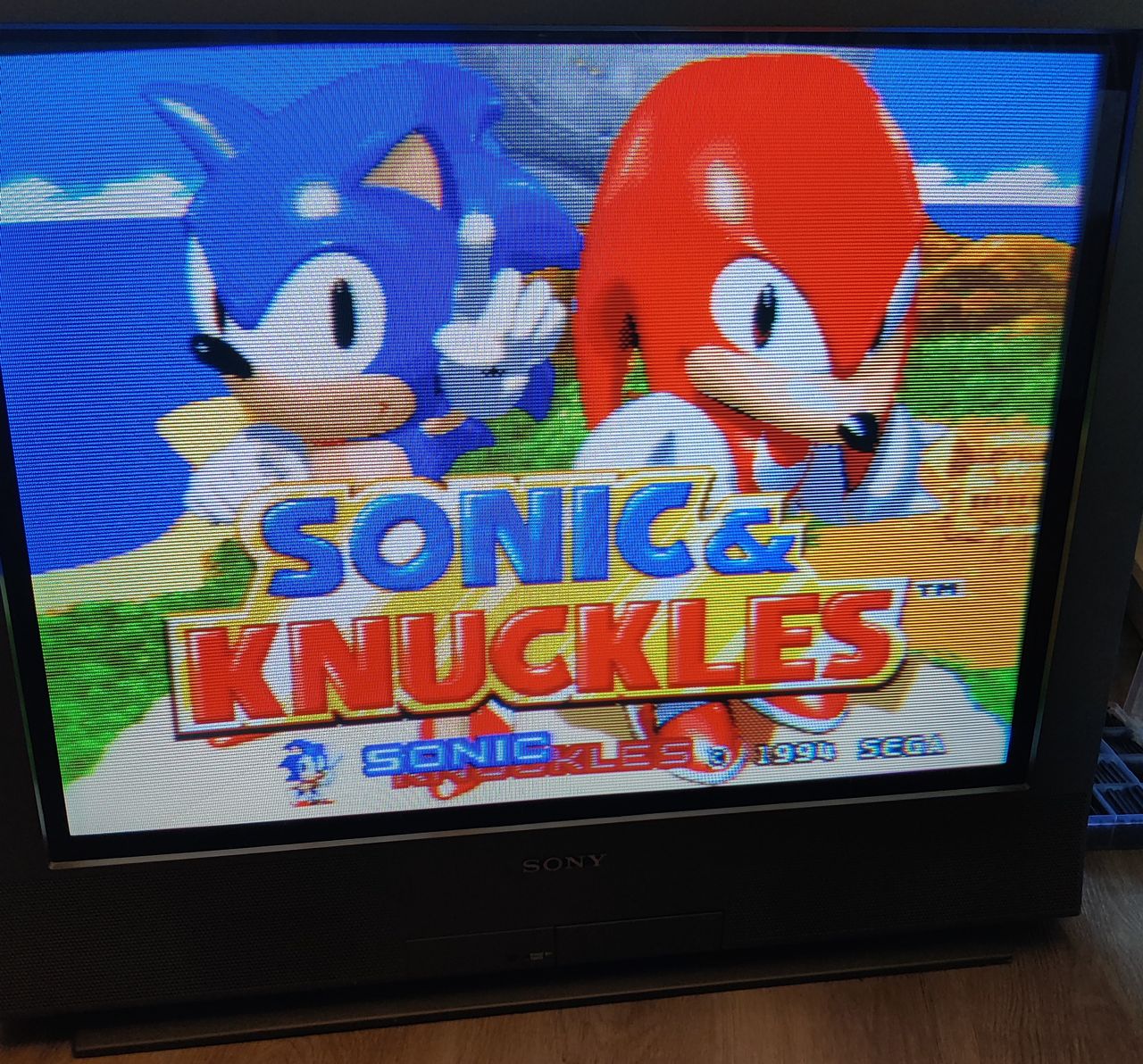
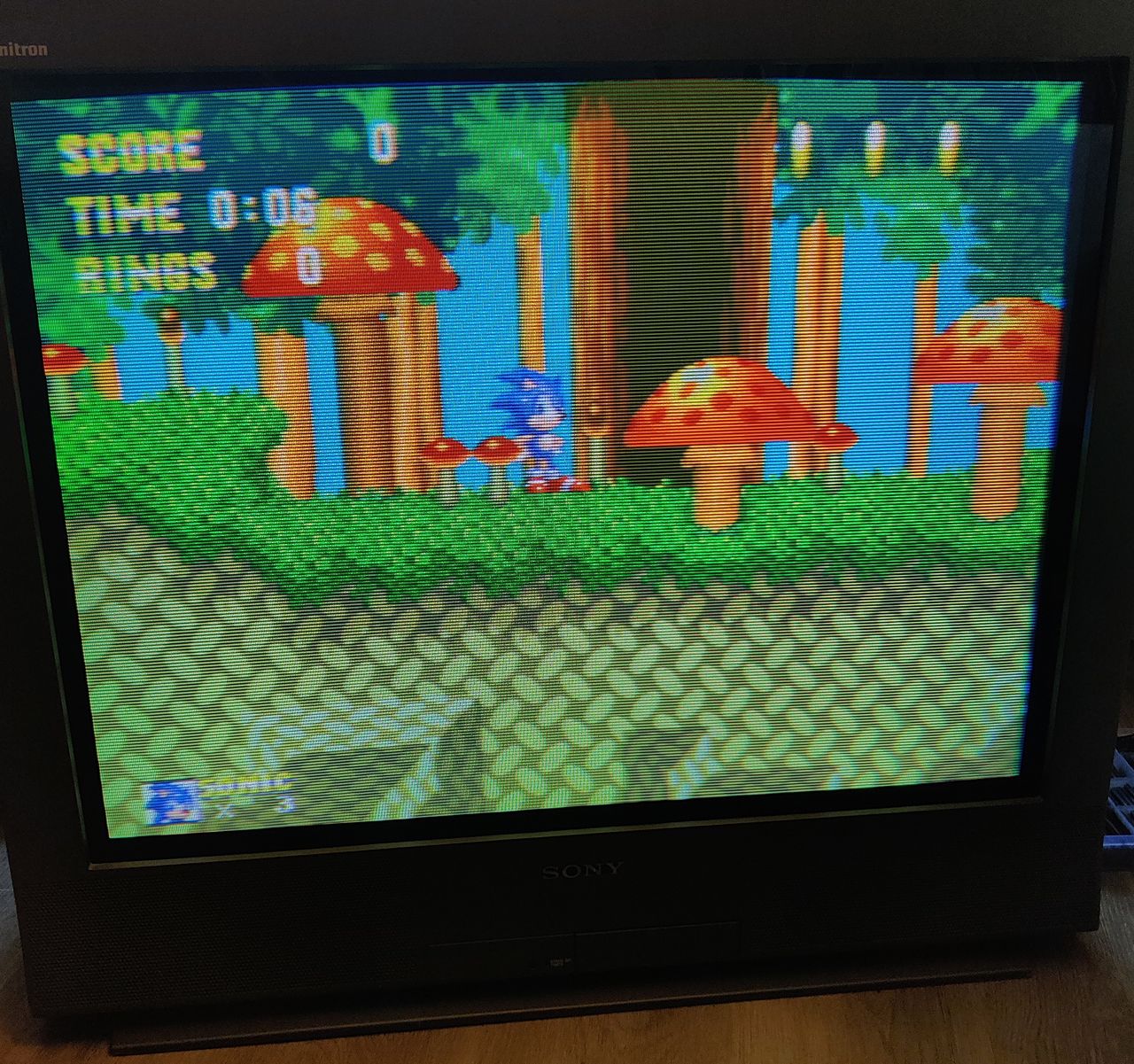
Pictures
Photos by manadream
This guide will cover how to RGB SCART mod the 32" Sony KV32-FS13. RGB Modding this CRT isn't too difficult, the hardest part is making the RGB SCART hole for the port imo.
Reference Photos
