Disney DT1350-C
Disney Mickey DT1350-C CRT RGB mod
This tutorial covers the RGB mod for Disney DT1350-C.
View full CRT details and more mod examples →
The RGB mod for this CRT is the same as Disney Princess DT1350-P
Contributors
Thank you to everyone who contributed to this guide:
- Sunthar — author, RGB tutorial
CRT safety
Caution
You can die doing this! So read carefully! CRT TV is not a toy. Do not open a CRT TV. If you don't have any prior knowledge about handling high voltage devices, this guide is not for you. CRT TV contains high enough voltage (20,000+ V) and current to be deadly, even when it is turned off.
Plan of attack
Service manuals
We can use the same service manual as the Disney Princess CRT.
Specs
- Year:
- Chassis: M3P935C
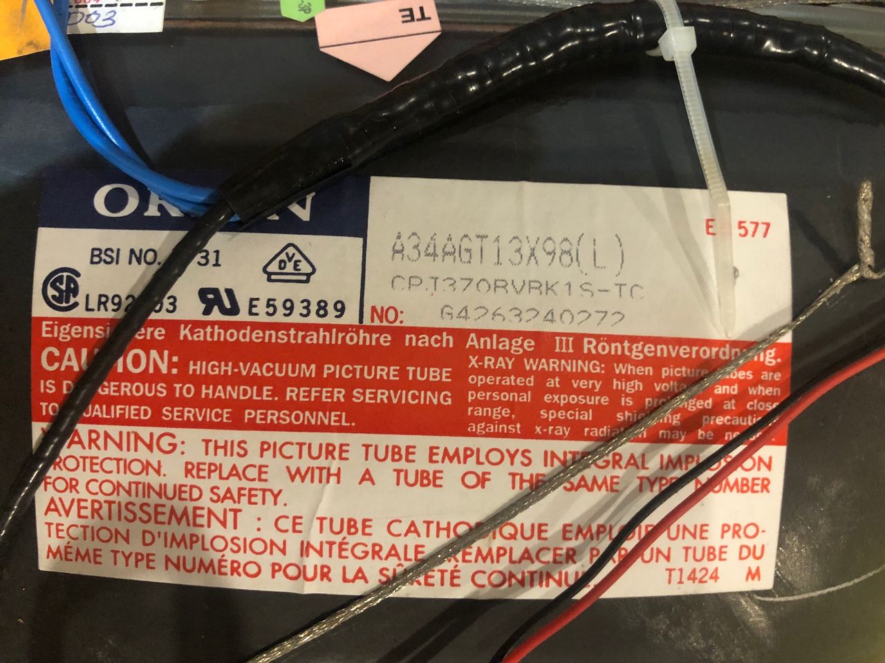
- Tube: Orion A34AGT13X98
- Jungle Chip: Renesas M61250BFP
- OSD Chip: Orion OEC7108A
- Screen Size: 13"
Schematics
OSD - OEC7108A 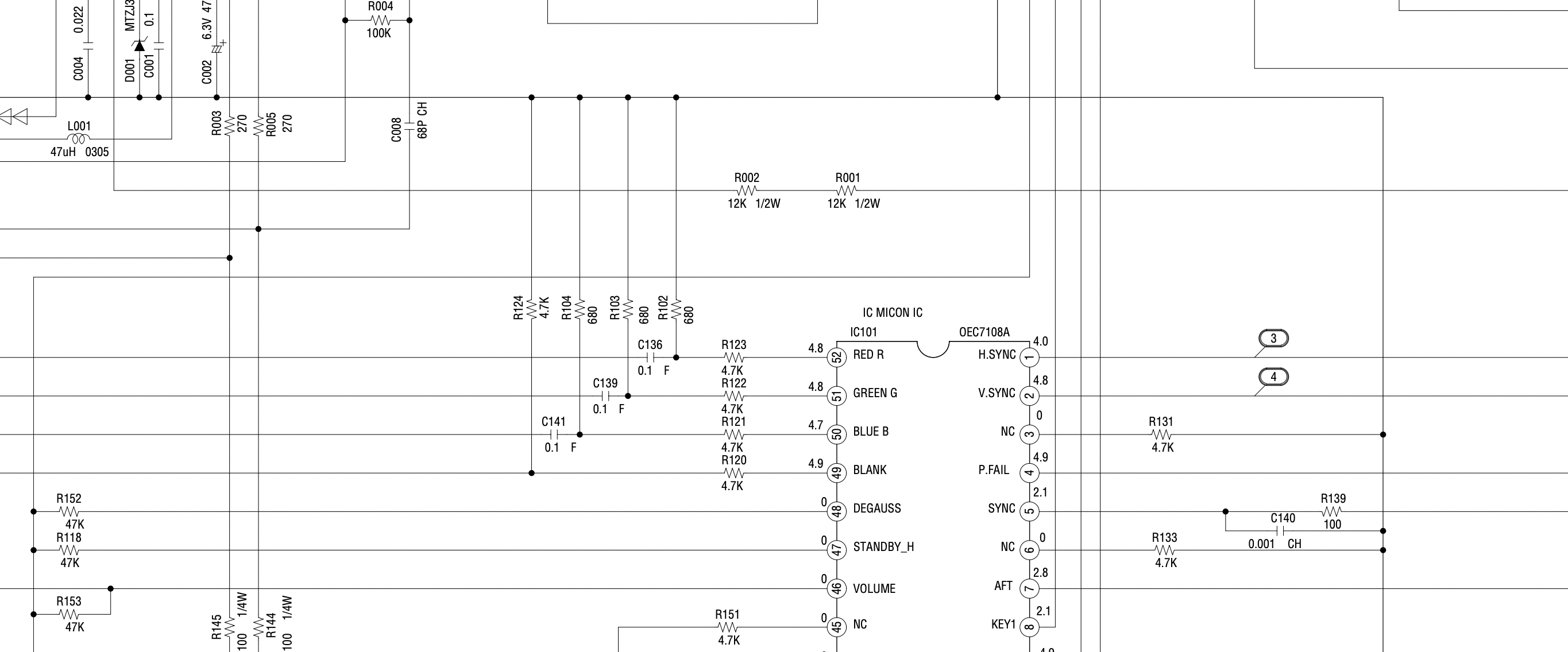
Chroma - M61250BFP 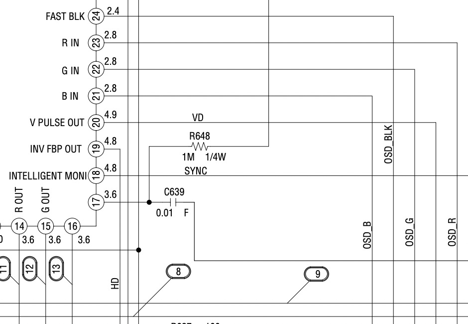
RGB mux diagram
Now that you roughly know what needs to be done, prepare for the mod. Place the board on a comfortable place. Make sure you are not putting pressure on the flyback or other components.
STEP 1: Remove the following components
Remove the three 680 ohm, RGB resistors to ground. Measure and mark before you remove.
- R102
- R103
- R104
STEP 2: Connect RGBs, Blanking and Audio
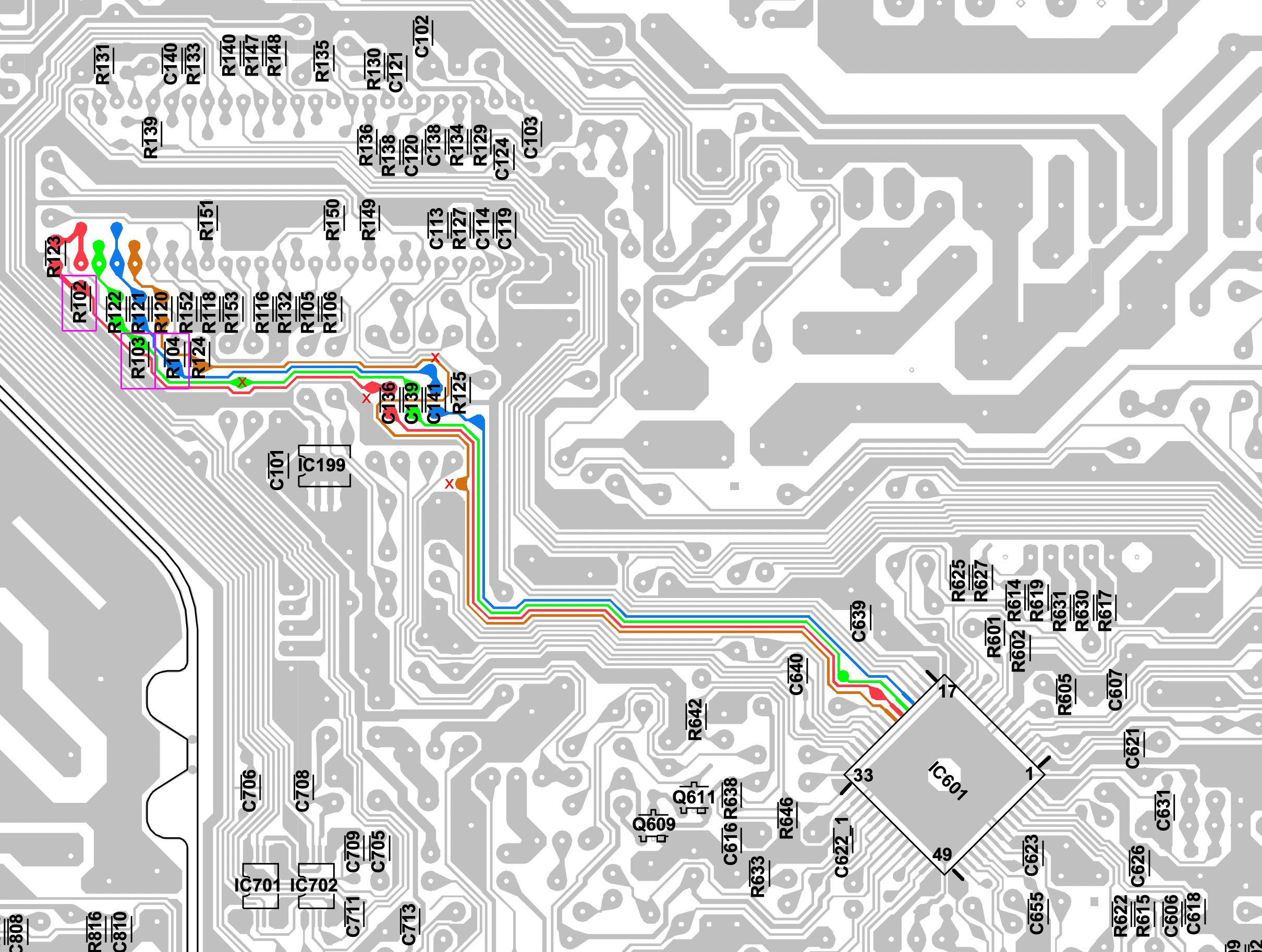
Remove the resistors marked with the pink square boxes. Wire the R, G, B and blanking wires to the points marked as 'X' on the diagram above. The mod on the CRT is fairly straight forward and follows the standard mux mod.
Close up of RGB and Blanking ![]()
Close up of Sync and Audio 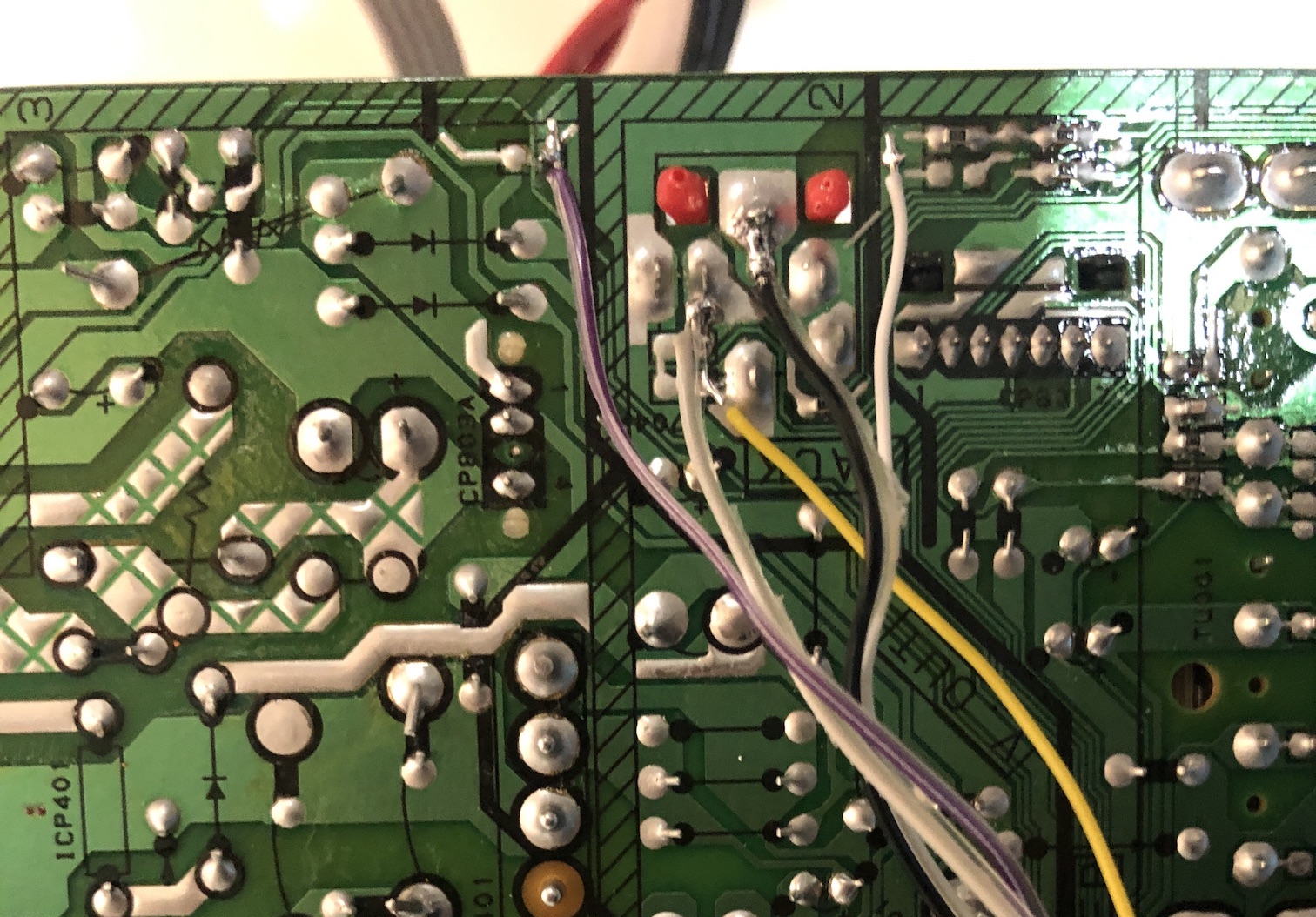
It's almost like the chassis designers were expecting someone to RGB mod this in the future. There are pads easily available on the board to solder the wires.
All wired up! Click to zoom in 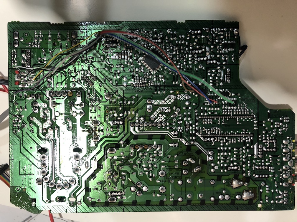
After attaching the bottom black panel to the board 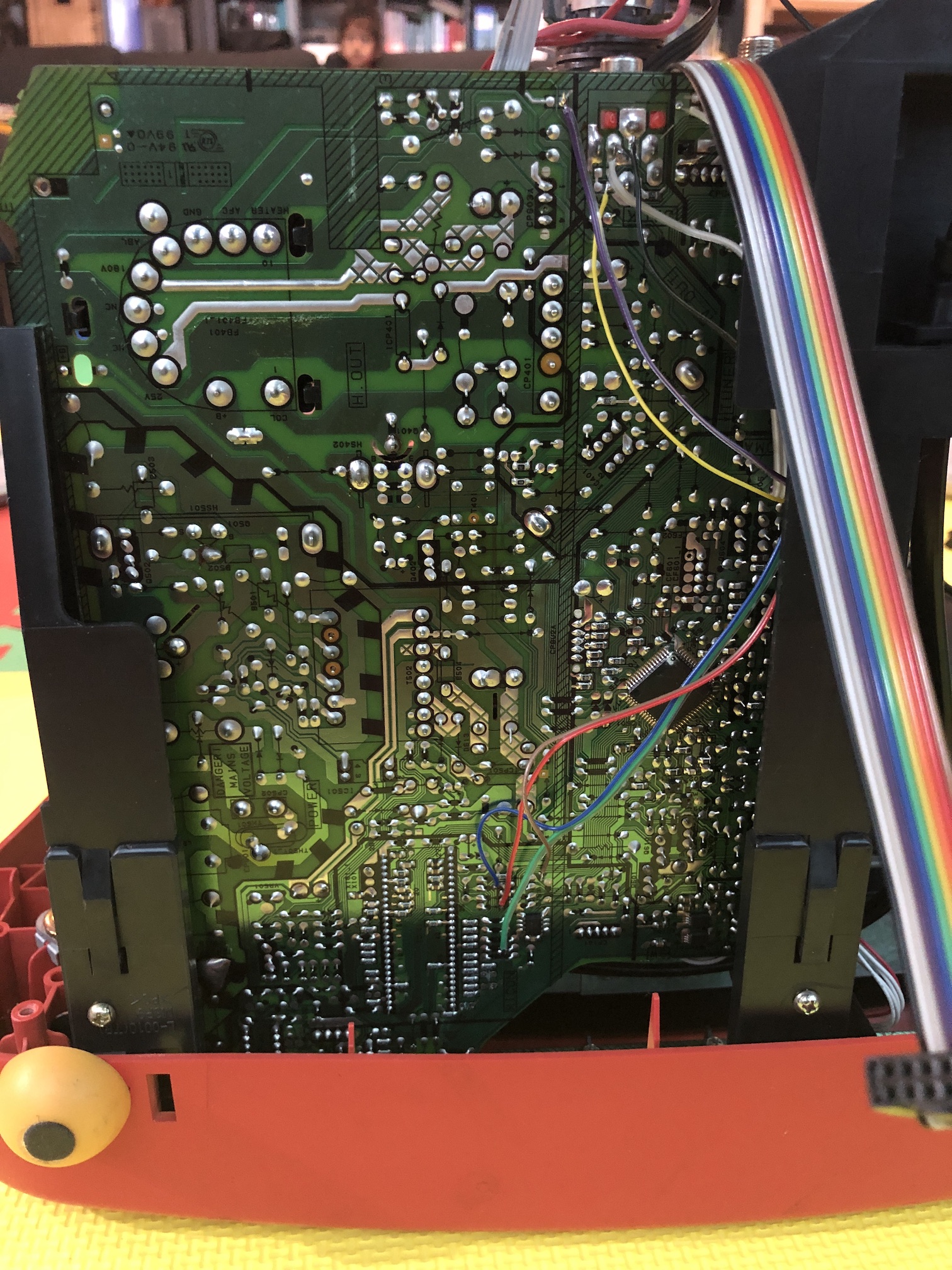
STEP 3: Build your mux board
This mod uses the RGB mux board. This is optional, but will make your mod easier and stable. You can also create the circuit presented in the schematics above without the board. Please also checkout the mux calculator to play with your own values.
| Component | Value |
|---|---|
| RGB/OSD inline resistor (chassis) | 4.7kΩ |
| Removed RGB/OSD resistor (chassis) | 680Ω |
| RGB termination (R1, R2, R3) | 75Ω |
| RGB inline (R4, R5, R6) | 1kΩ |
| Audio LR (R7, R8) | 1kΩ |
| Diode (R9) | 1N4148 |
| Blanking Ground Resistor (R10) | open |
| Blanking Resistor (R11) | 4.7kΩ |
Picture from an older board revision. 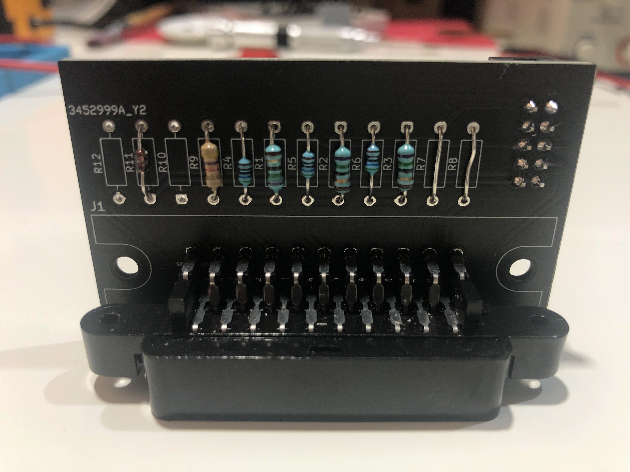
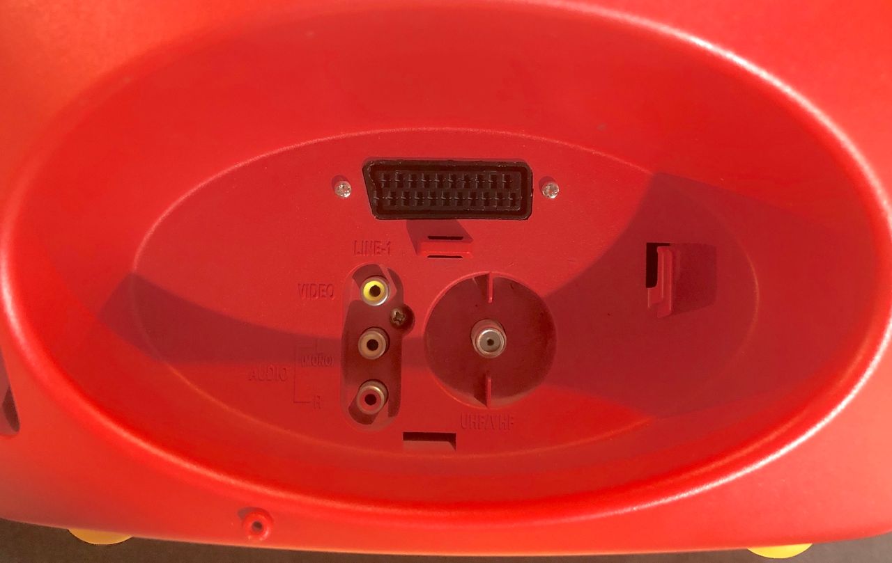
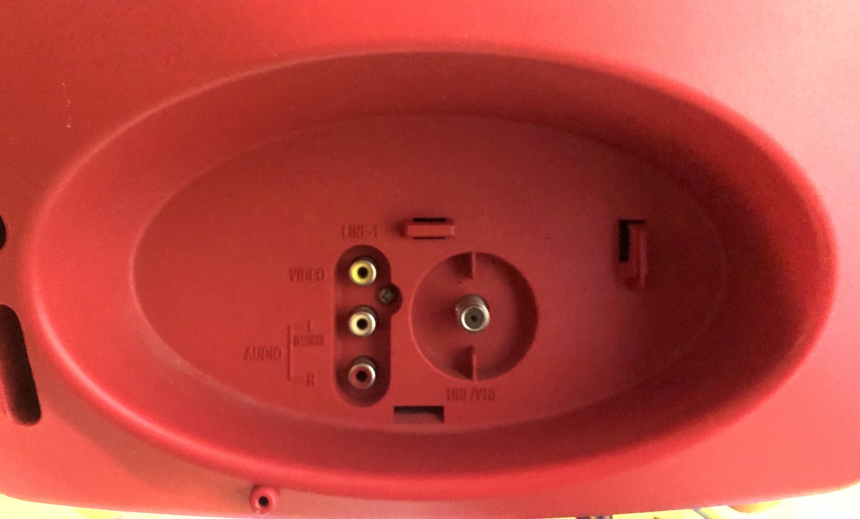
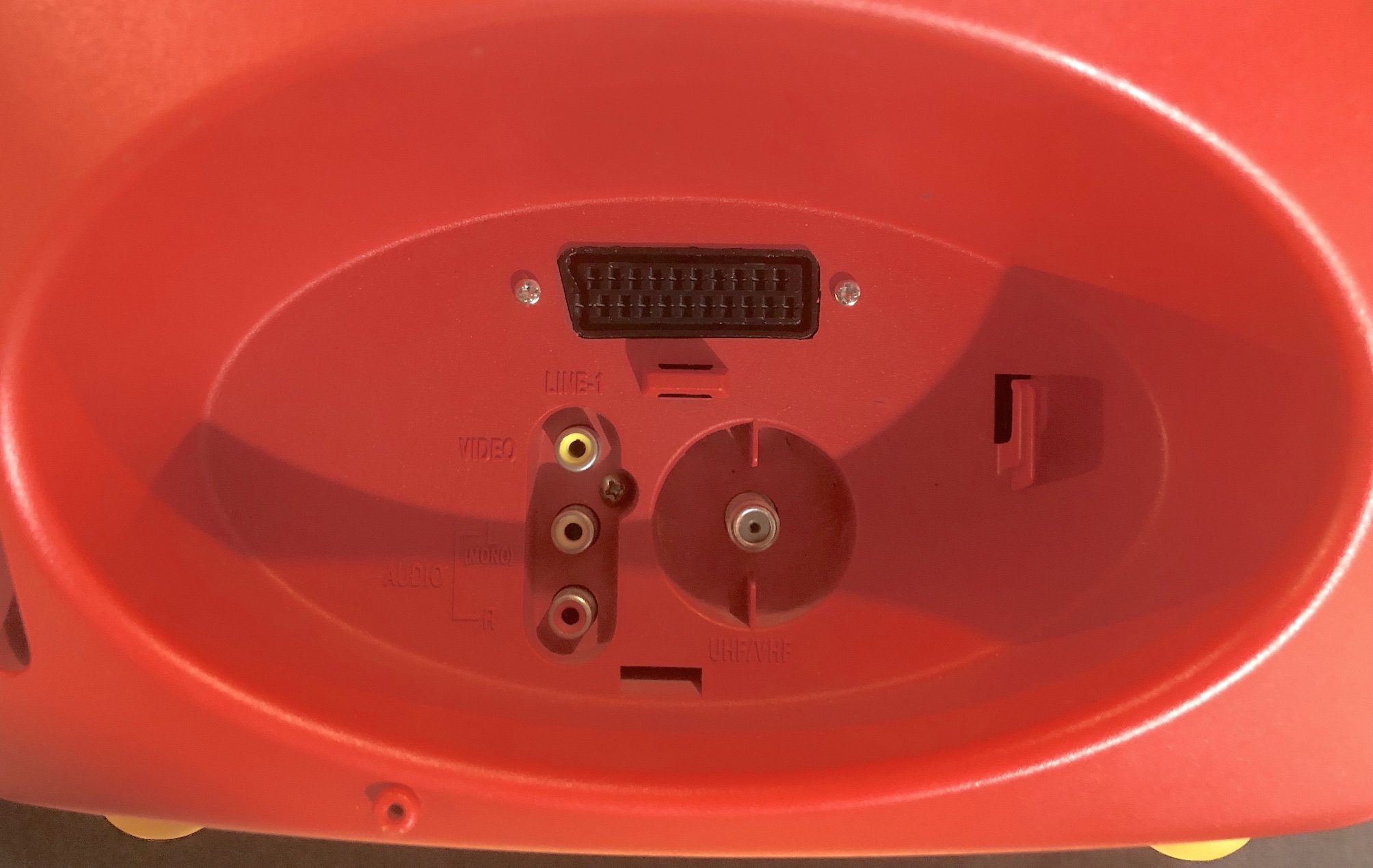
STEP 4: Attach the female SCART connector to TV
Back of the CRT 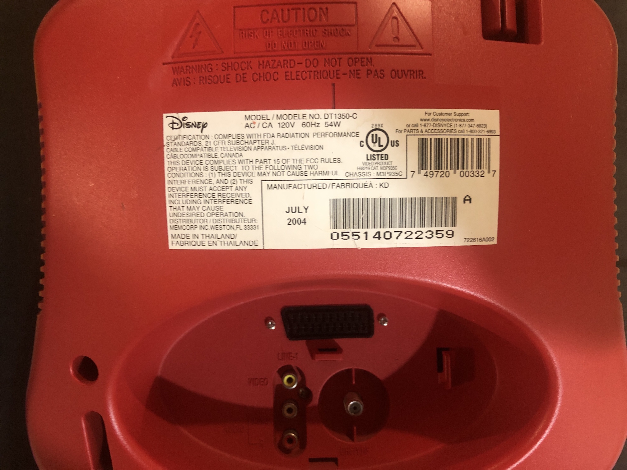
Before and After SCART
Getting into service menu
While pressing the Volume down on the CRT, press 9. Only adjustment I had to make was the horizontal phase (shift).
Pictures of the mod
Games
SNES - Super Mario World 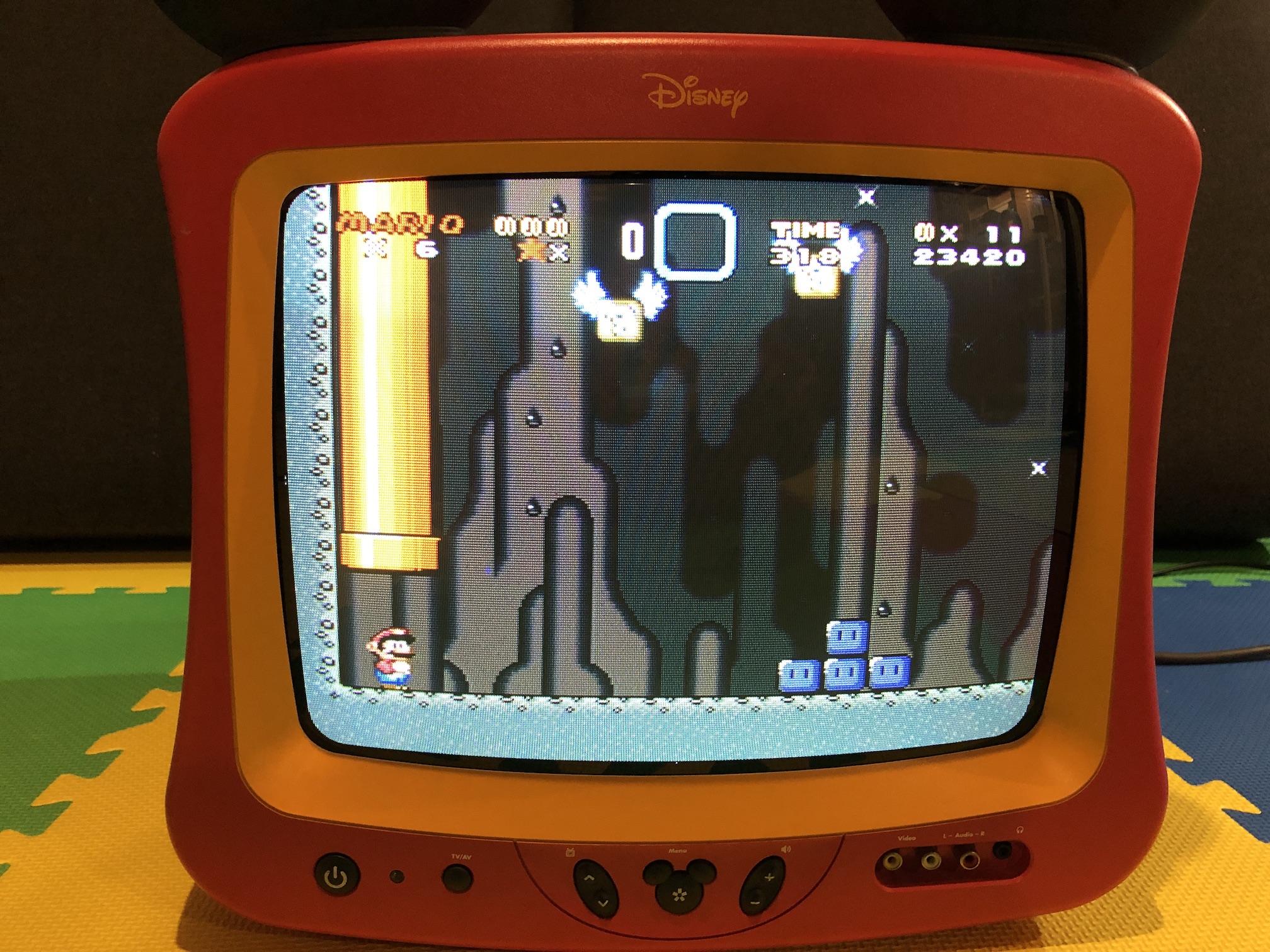
SNES - Super Mario World (Close up) 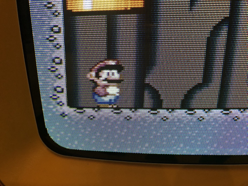
SNES - Mega Man 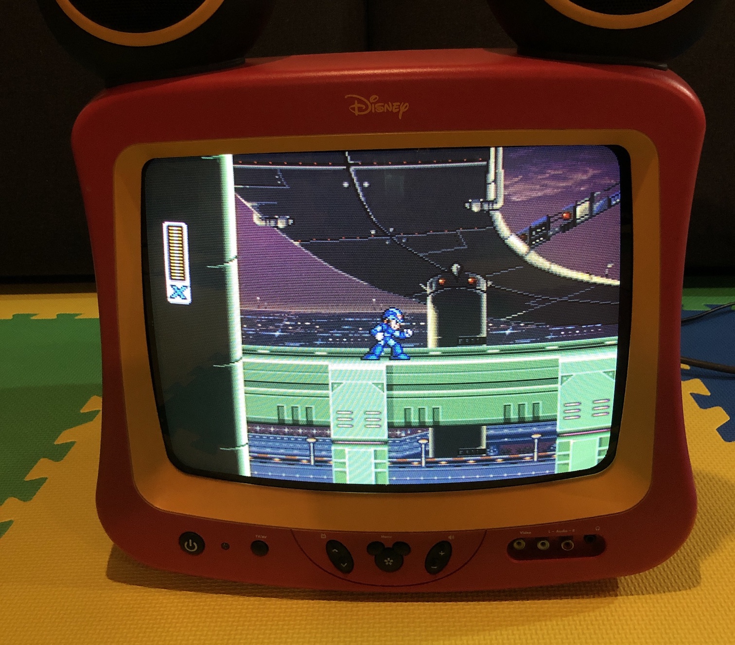
SNES - Mega Man 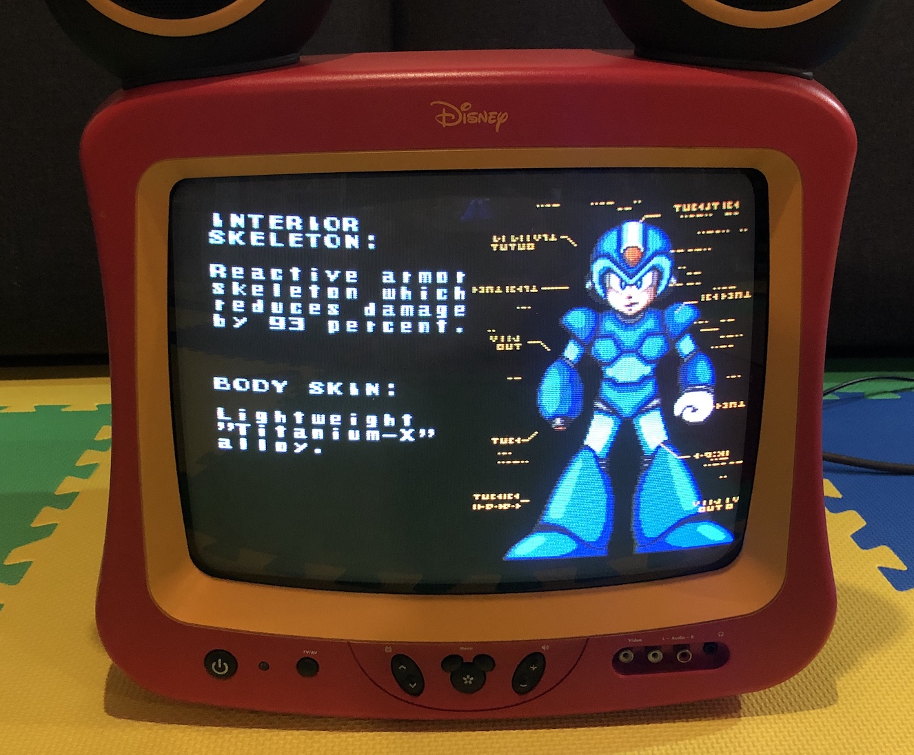
SNES - Mickey's Playtown Adventure 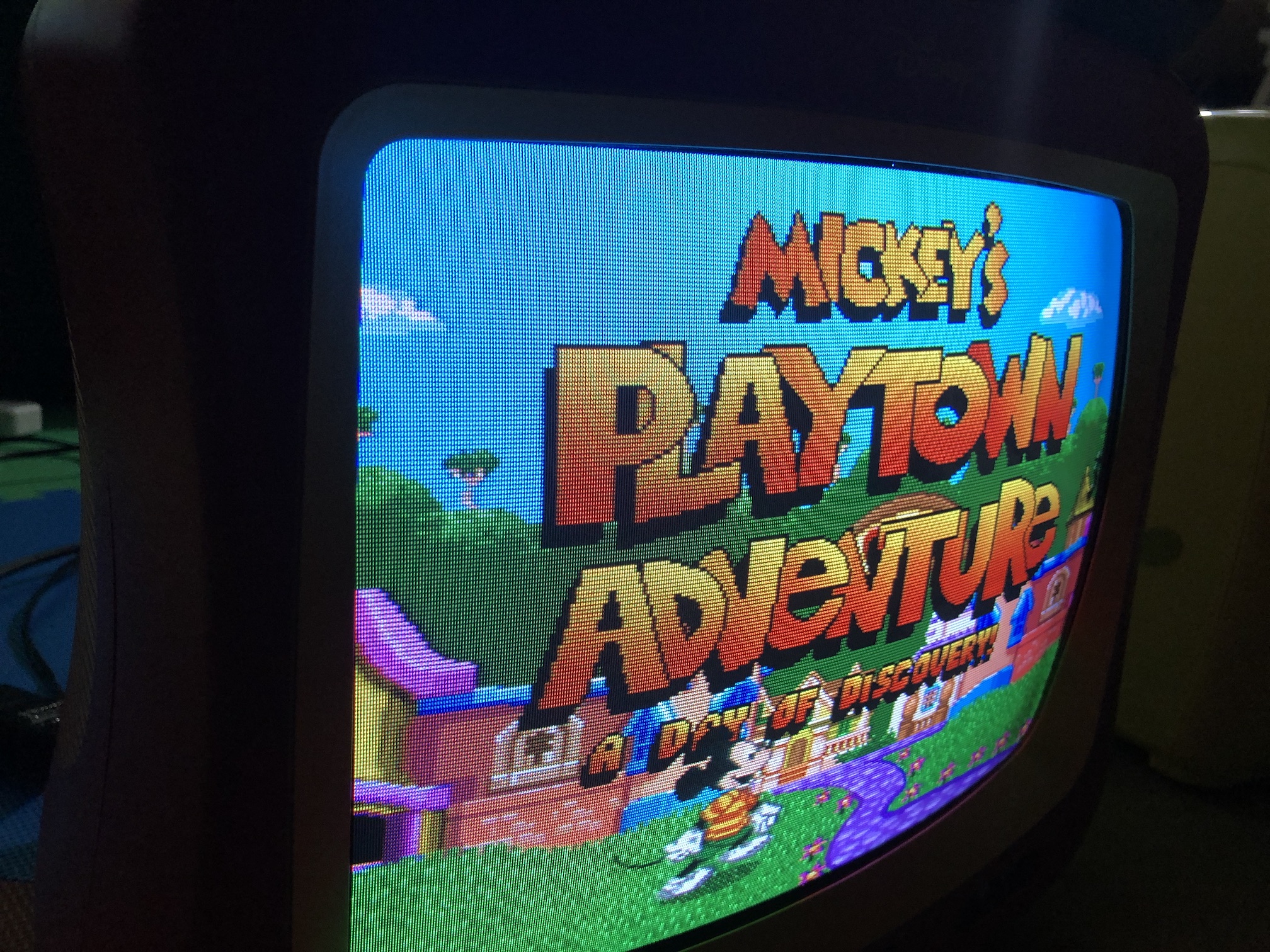
NES - Adventure Island 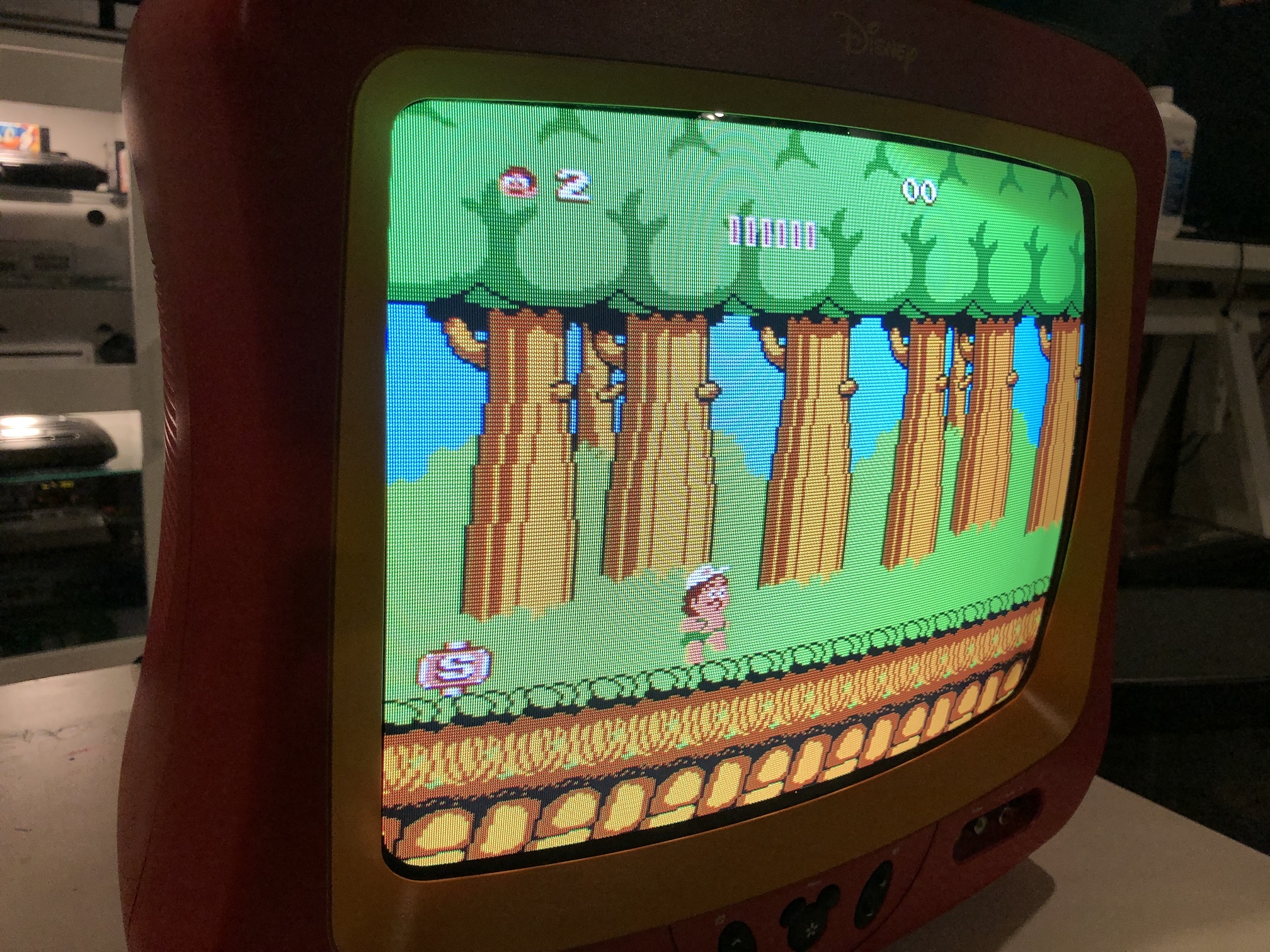
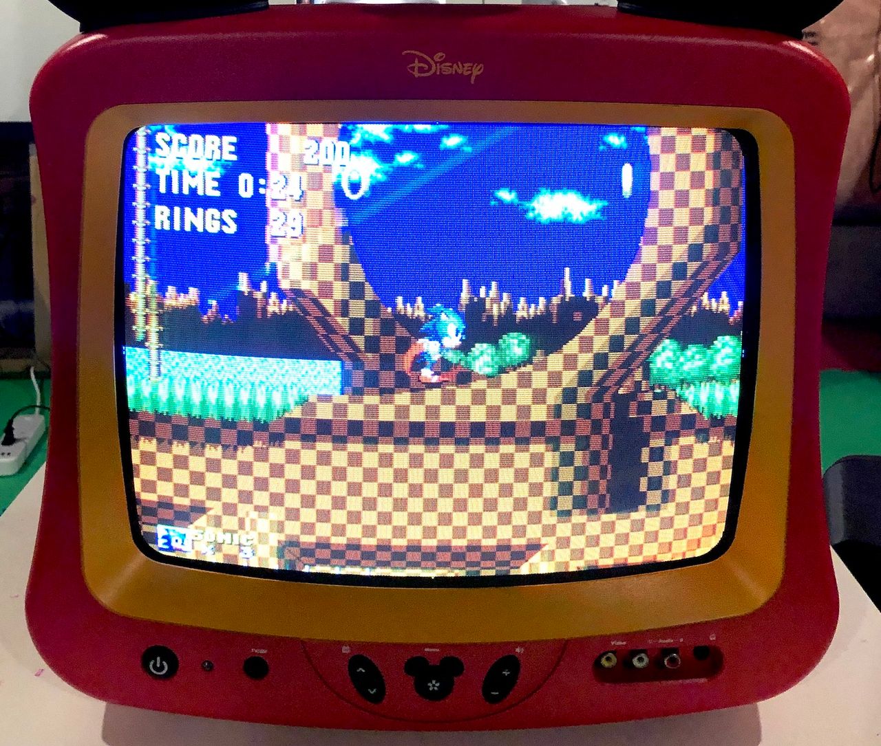
Sega Genesis - Sonic 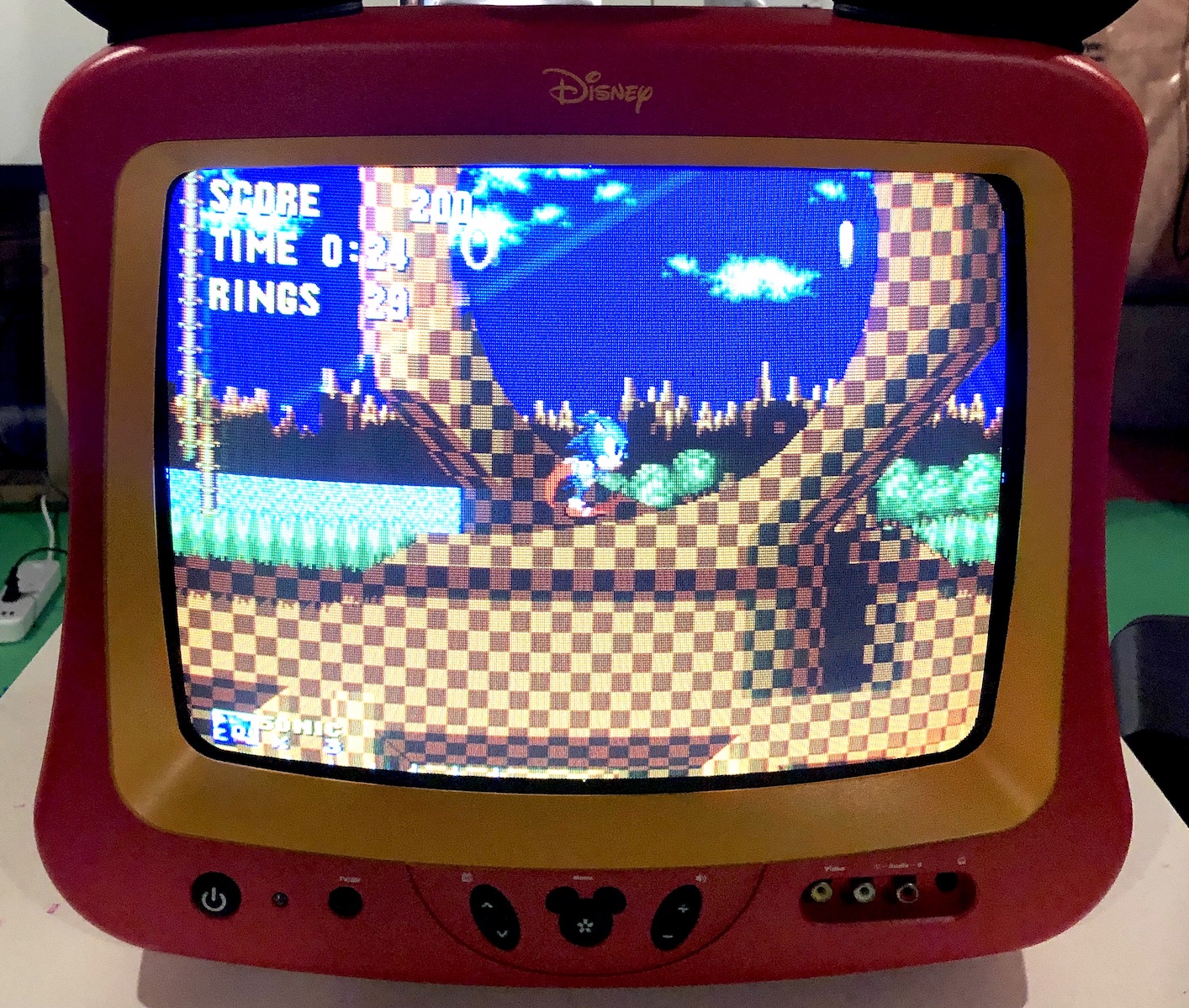
PS1 - Boot 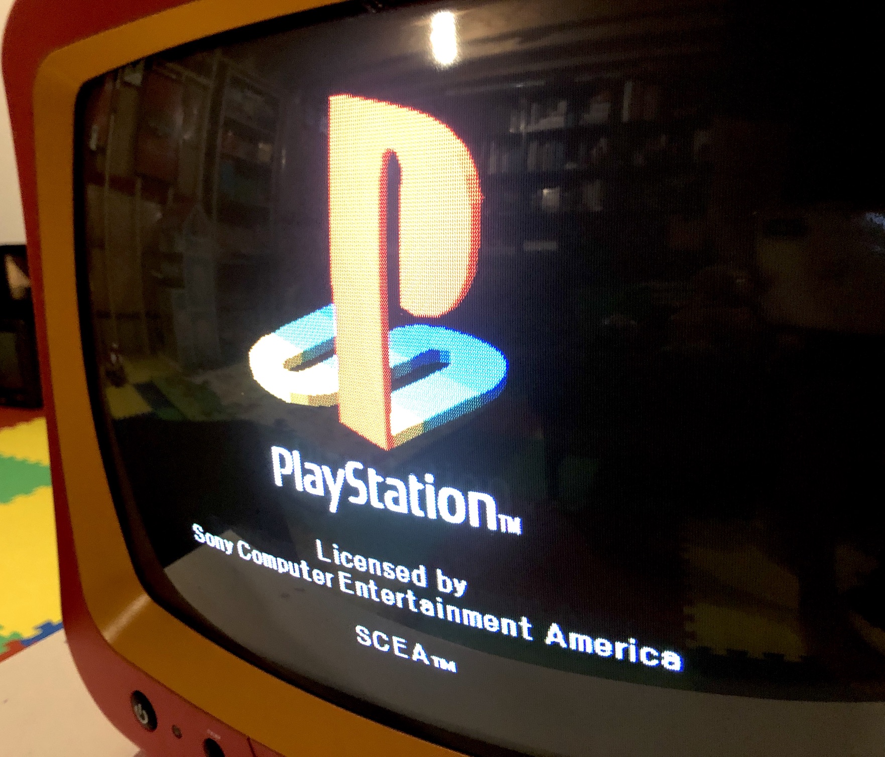
Patterns
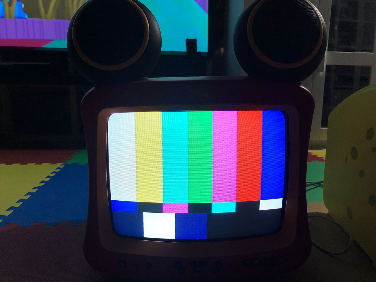
SMPTE Colors 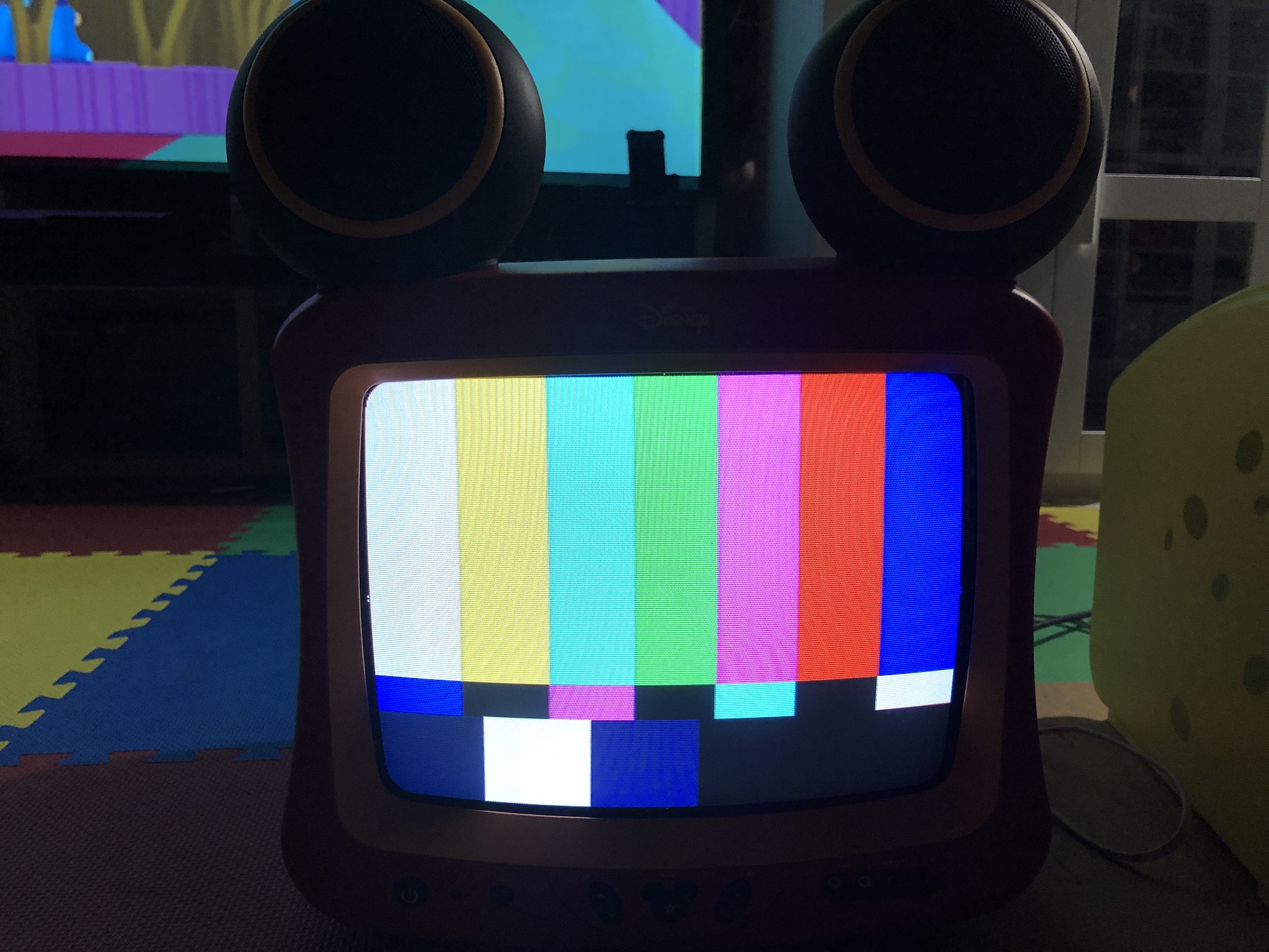
Grid (After the HPOS shift on service menu) 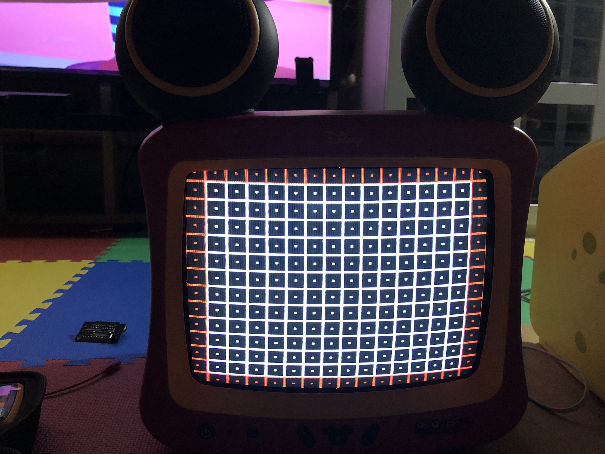
Misc pictures
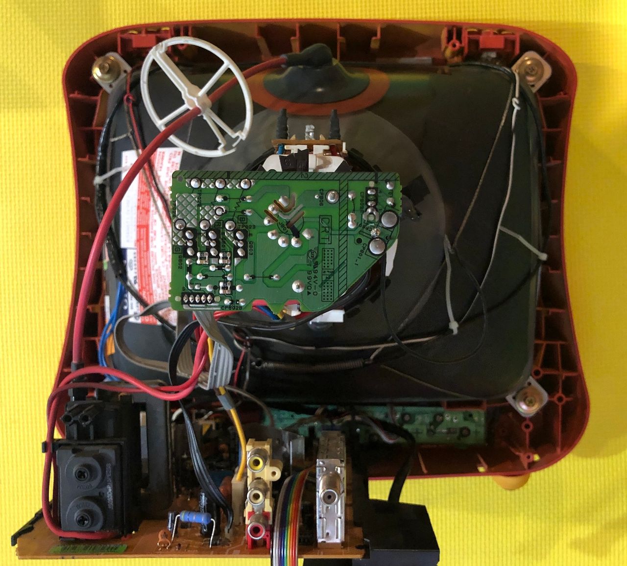
Board top view
Tube 
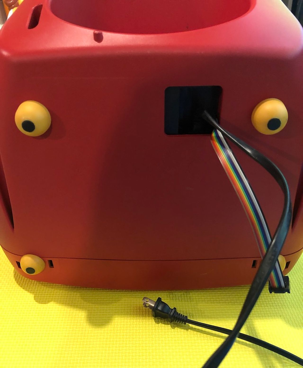
AC Cord wiring 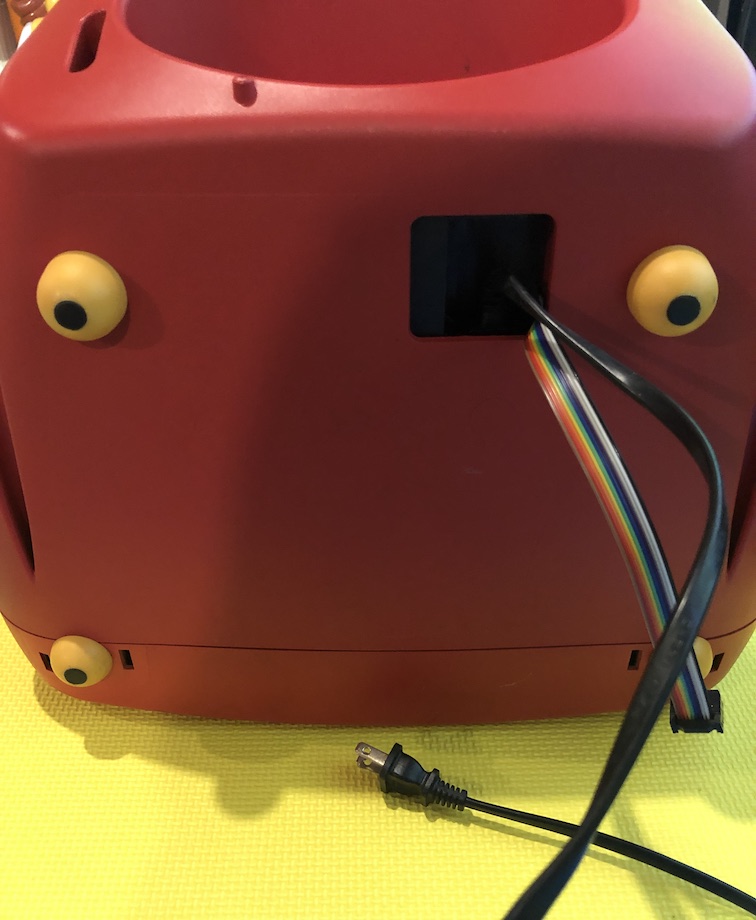
Back full 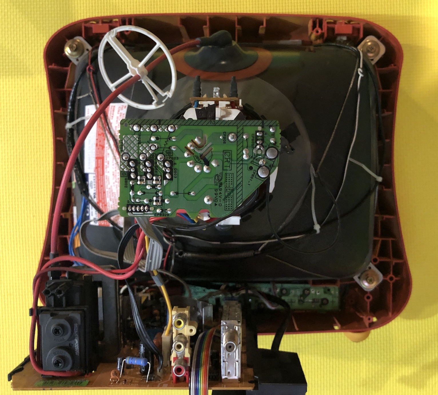
Warning
This tv has a weird wiring method where the AC cord goes through the bottom of the back cover. Also, this version of the Disney Princess CRT doesn't stand still without the back cover.
Pictures
Reference Photos