Sony (AA-1)
Less than 1 minute
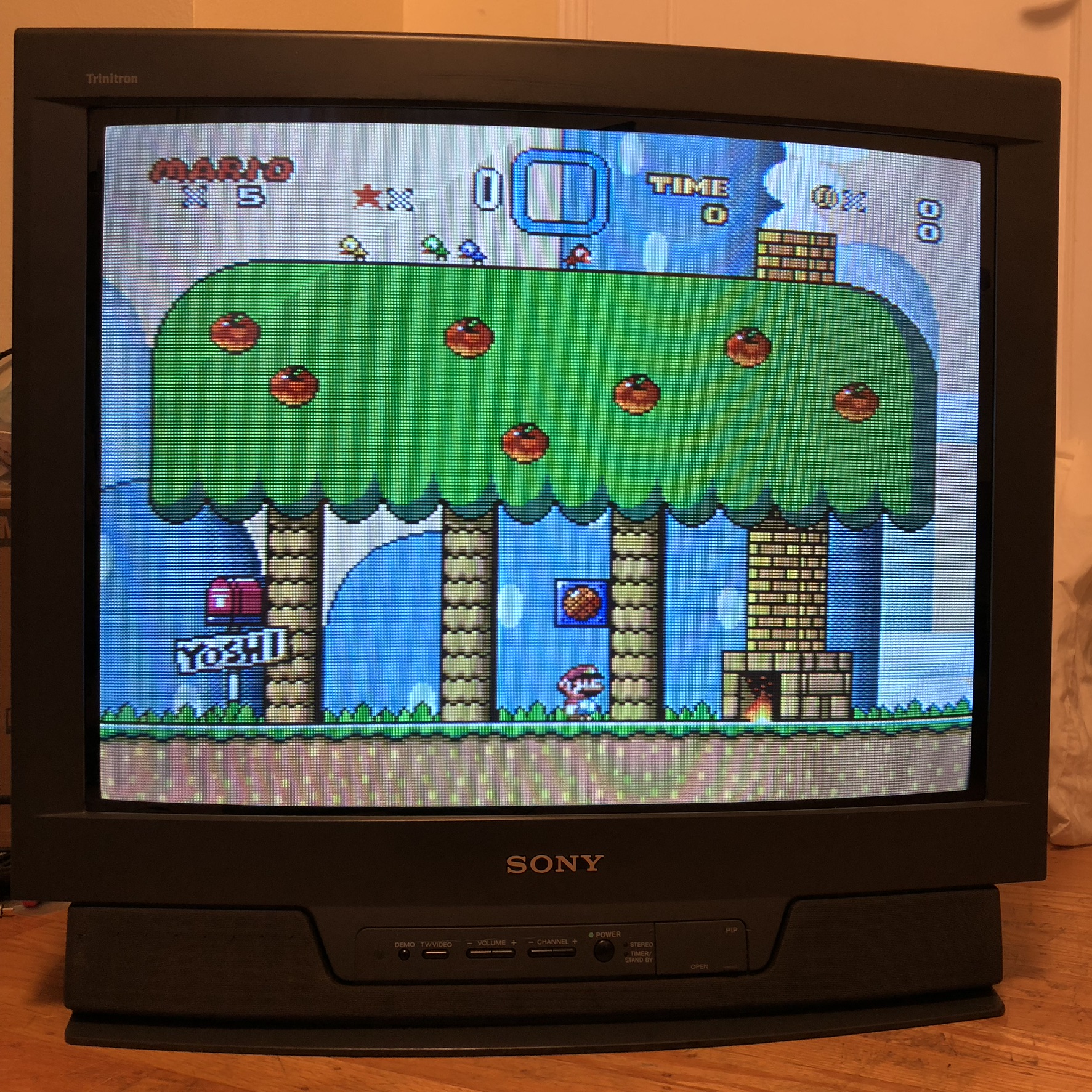
Sony AA-1 chassis RGB mod
Bring your AA-1 based Sony CRT to life with vibrant RGB colors! Below are a few AA-1 models that can RGB modded.
- Sony KV-27V10
- Sony KV-20V50
- Sony KV-27V55
- Sony KV-32S12
- Sony KV-32S16
- Sony KV-32V16
- Sony KV-27S10
- Sony KV-27S15
- Sony KV-32S10
- Sony KV-32S15
- Sony KV-27TS29
- Sony KV-27TS32
- Sony KV-27TS36
Sony KV-27V10 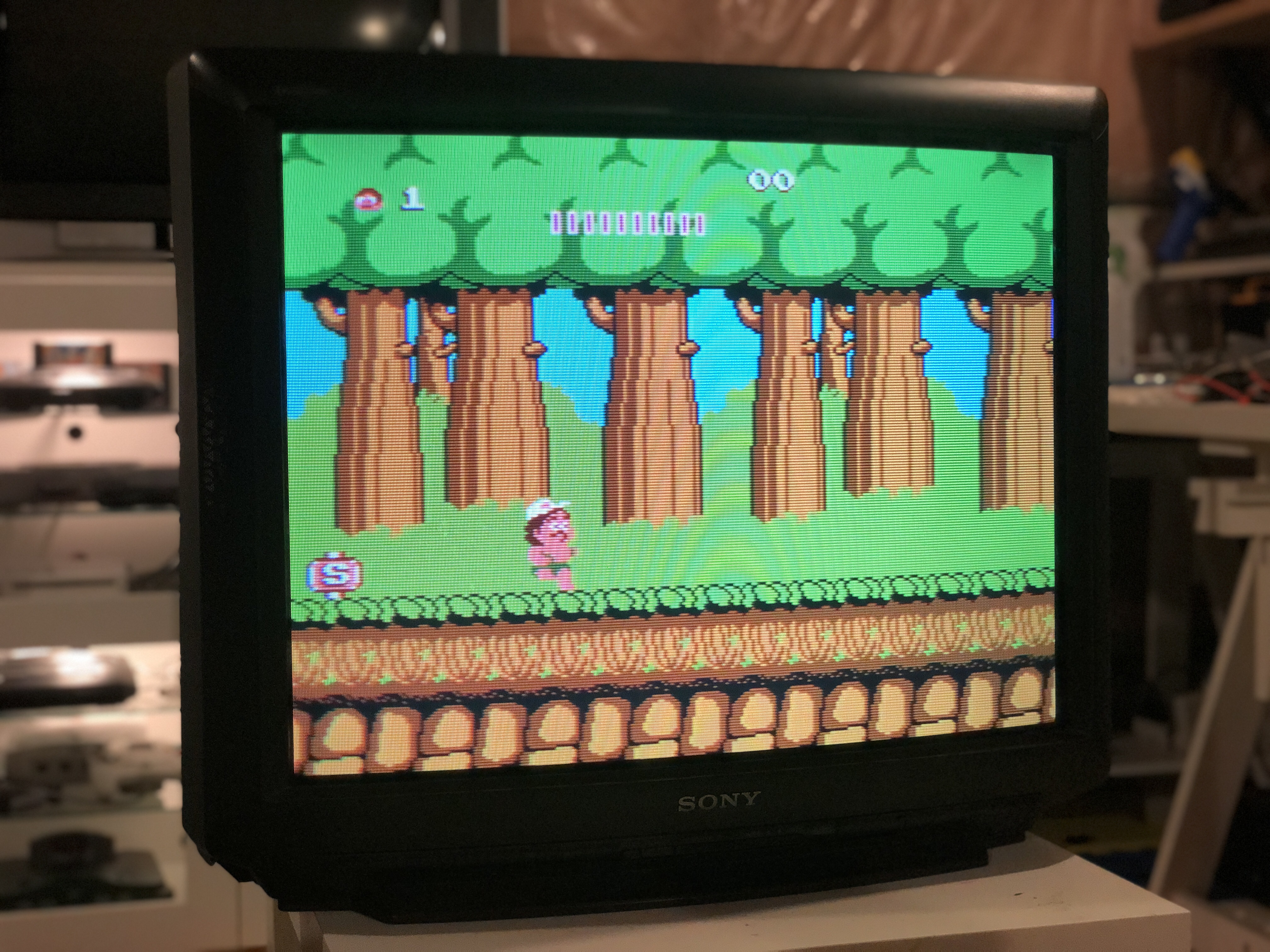
Sony KV-27V55 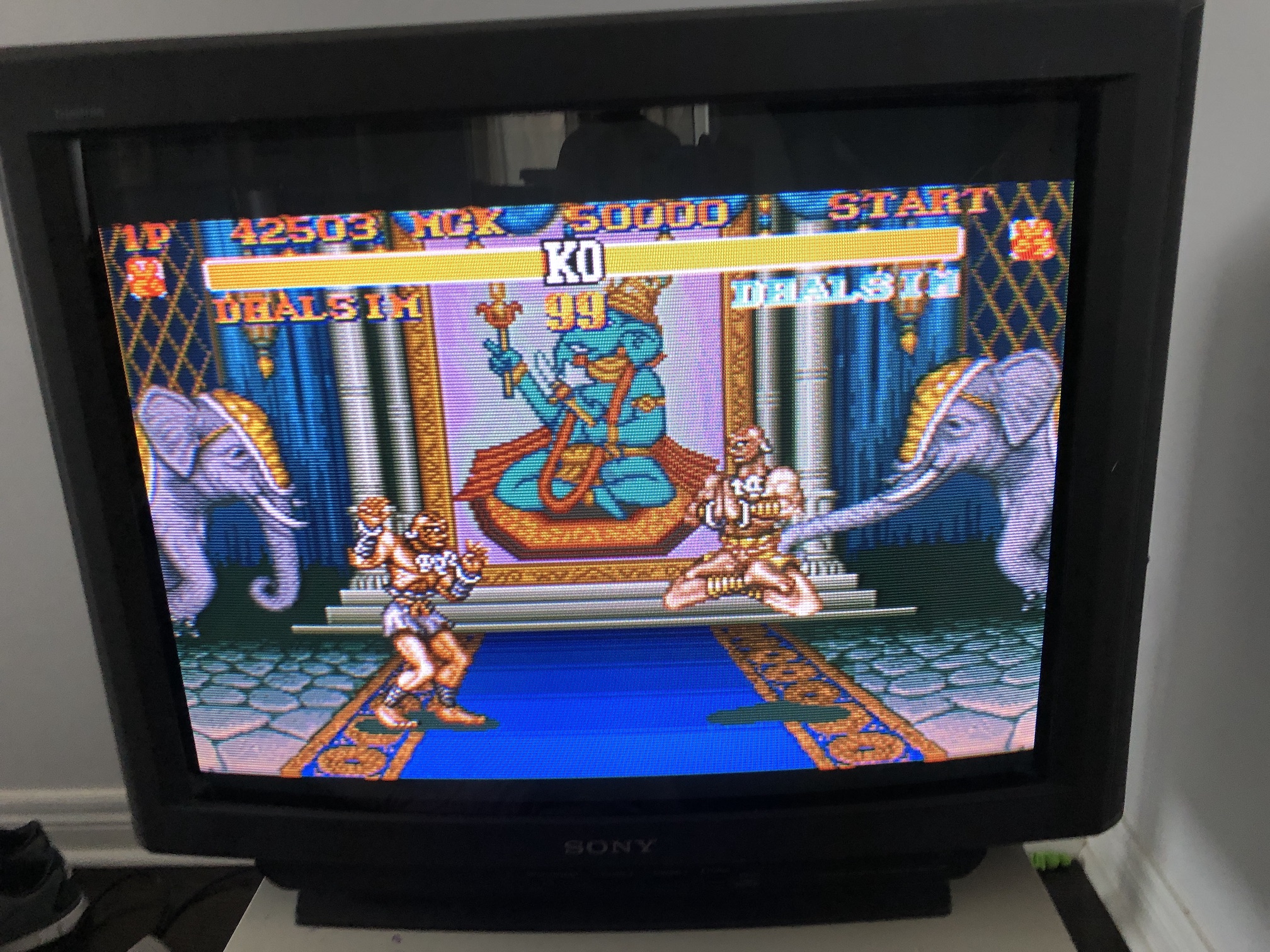
Sony KV-27TS36