Sharp 36J-S400
Sharp 36J-S400 CRT RGB mod
This tutorial covers the RGB mod for Sharp 36J-S400.
View full CRT details and more mod examples →
These instructions should also work for other SN-71 chassis based sets. Example:
- Sharp 19L-M100
Contributors
Thank you to everyone who contributed to this guide:
No contributors listed yet.
CRT safety
Caution
You can die doing this! So read carefully! CRT TV is not a toy. Do not open a CRT TV. If you don't have any prior knowledge about handling high voltage devices, this guide is not for you. CRT TV contains high enough voltage (20,000+ V) and current to be deadly, even when it is turned off.
Plan of attack
Manuals and Datasheets
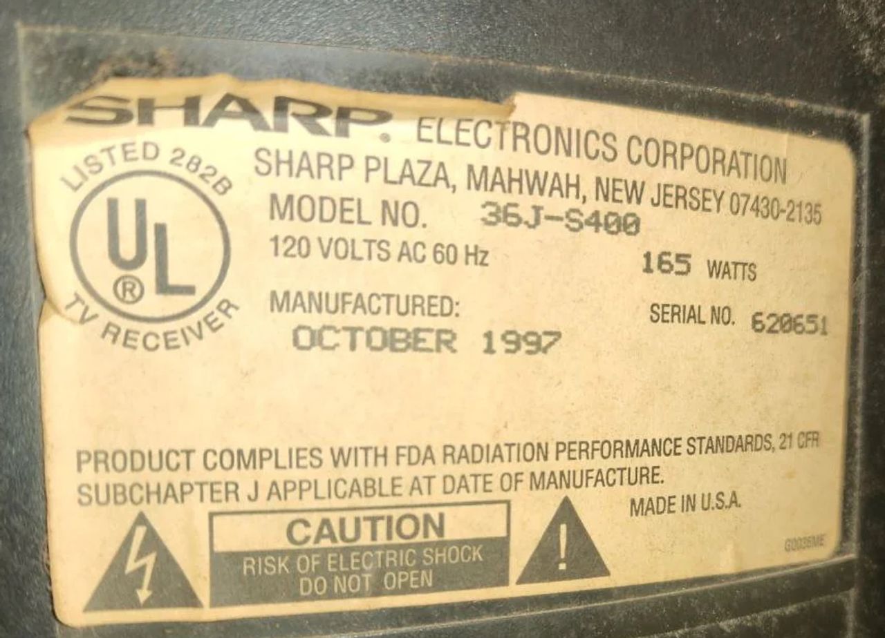
Specs
- Year: 1997
- Chassis: SN-71
- Jungle Chip: Sharp IX2573CE
- OSD Chip: IX2947CE
- Screen Size: 36"
Schematics
IX2573CE Chroma Chip
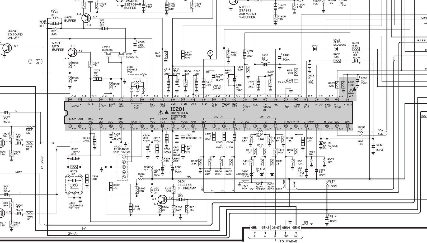
RGB mux diagram
Prepare the mux diagram. If you are building your own circuit, this diagram should help.
Calculating the RGB external resistor value
Love it when we can put theories to use! Formula from our theory page!

RGB external resistor value = 0.7 x (6800 + 75) - (75 x 5) / (5 - 0.7) = (4812 - 375) / 4.3 = 1030 ohm
~ 1 Kohm resistors should do the job.
Performing the mod
Now that you roughly know what needs to be done, prepare for the mod. Place the board on a comfortable place. Make sure you are not putting pressure on the flyback or other components.
STEP 1: Remove the following components
Remove the following components. RGB resistors to the ground. Measure twice and mark before you remove.
- R803 (2.2 kΩ)
- R804 (2.2 kΩ)
- R805 (2.2 kΩ)
STEP 2: Connect RGBs, Blanking and Audio
RGB and Blanking ![]()
Sync and Audio 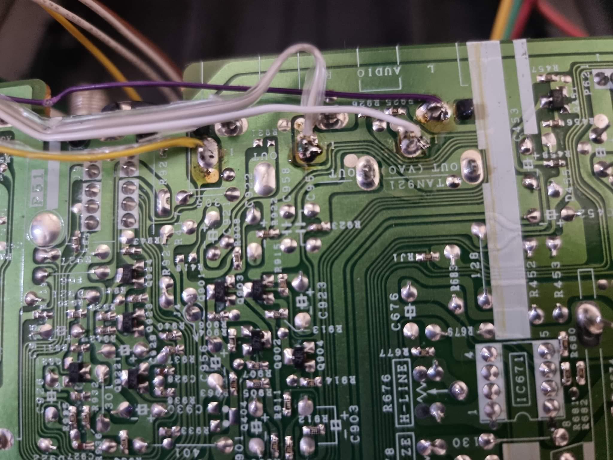
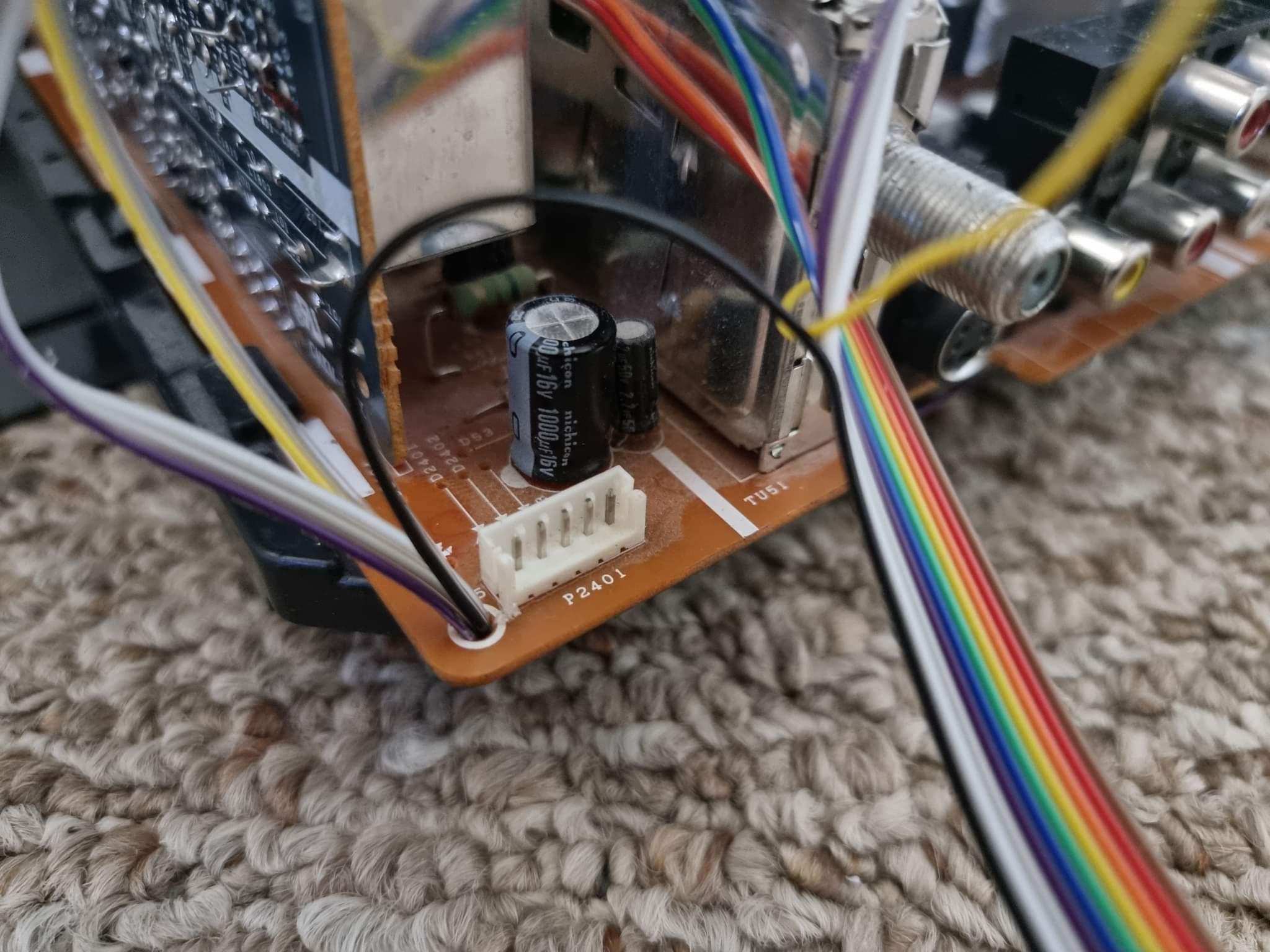
Wire Routing 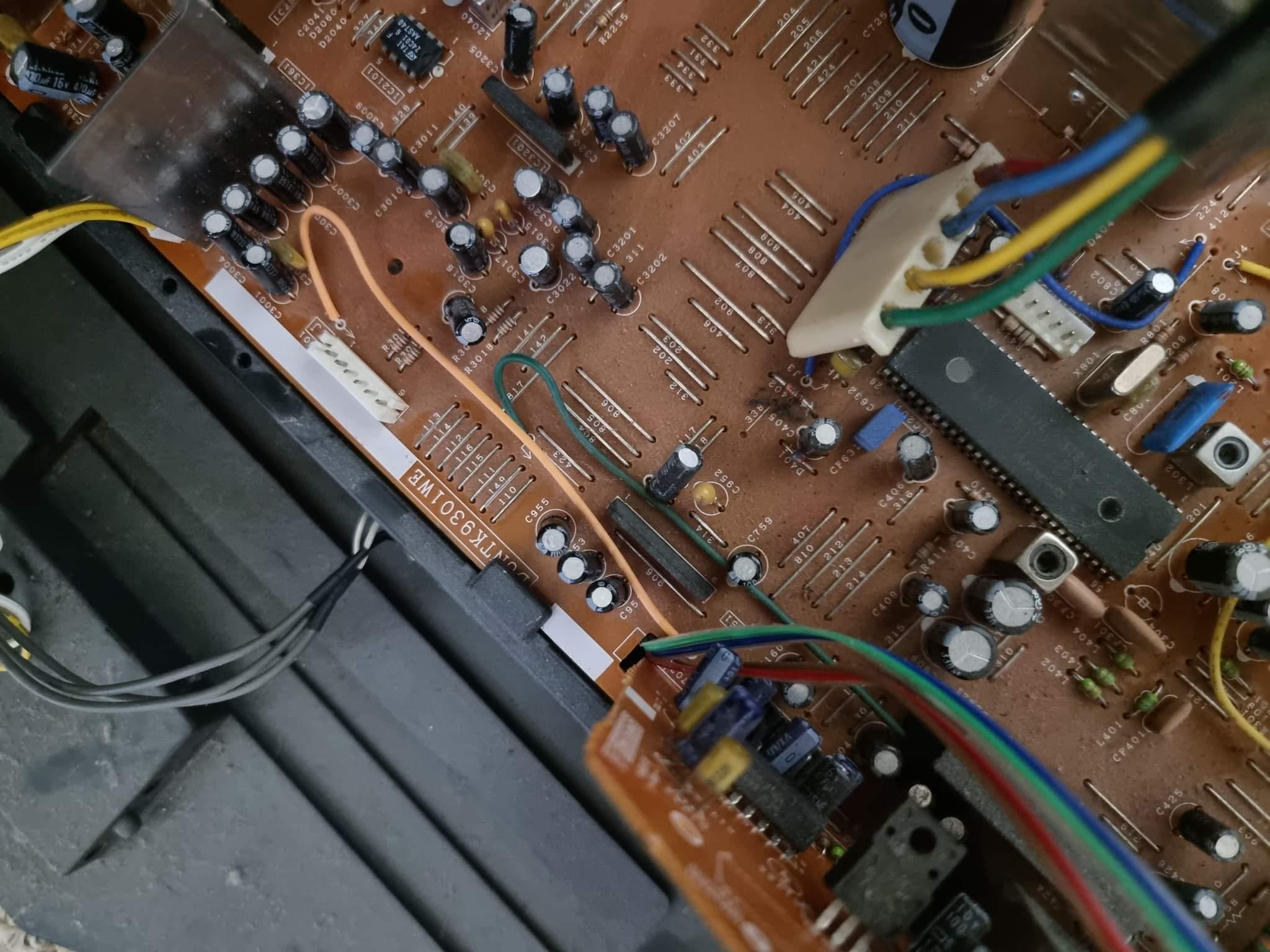
STEP 3: Build your mux board
This mod uses the RGB mux board. This is optional, but will make your mod easier and stable. You can also create the circuit presented in the schematics above without the board. Please also checkout the mux calculator to play with your own values.
| On Sharp CRT Chassis | 36J-S400 |
|---|---|
| CRT RGB inline resistor | 6.8kΩ |
| CRT RGB ground resistors removed | 2.2kΩ |
| 0.1μF caps replaced | No |
| Add diodes on chassis RGB lines? | Yes |
| Add blanking diode on chassis | Yes |
| RGB mux board | 36J-S400 |
|---|---|
| Mux board RGB termination (R1, R2, R3) | 75Ω |
| Mux board RGB inline resistors (R4, R5, R6) | 2.2kΩ |
| Mux board Audio LR (R7, R8) | 1kΩ |
| Mux board blanking diode (R9) | 1N4148 |
| Mux board blanking ground resistor (R10) | open |
| Mux board blanking resistor (R11) | 1kΩ |
STEP 4: Attach the female SCART connector to TV
Creating a SCART cutout and mounting it is an art. I have a dedicated section for it.
How to create and mount a SCART female plug?
Remote Control for this TV
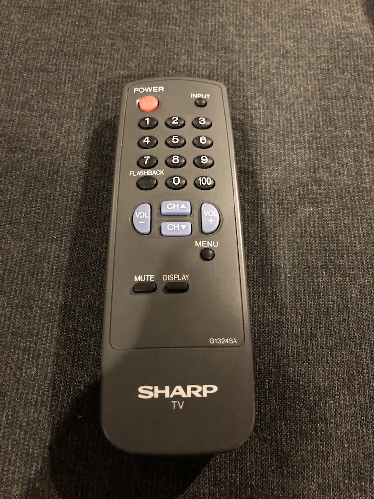
Getting into service menu
While pressing the Vol-up and Ch-up buttons at the sametime, plug the AC cord into a wall socket.
Pictures
Reference Photos