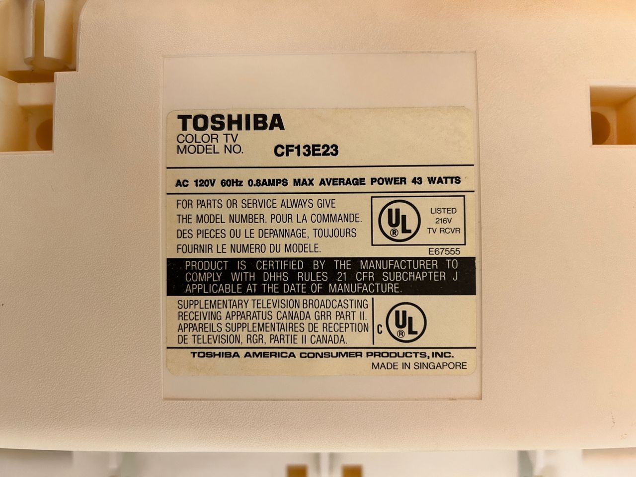
Toshiba CF13E23
Toshiba CF13E23 CRT RGB mod
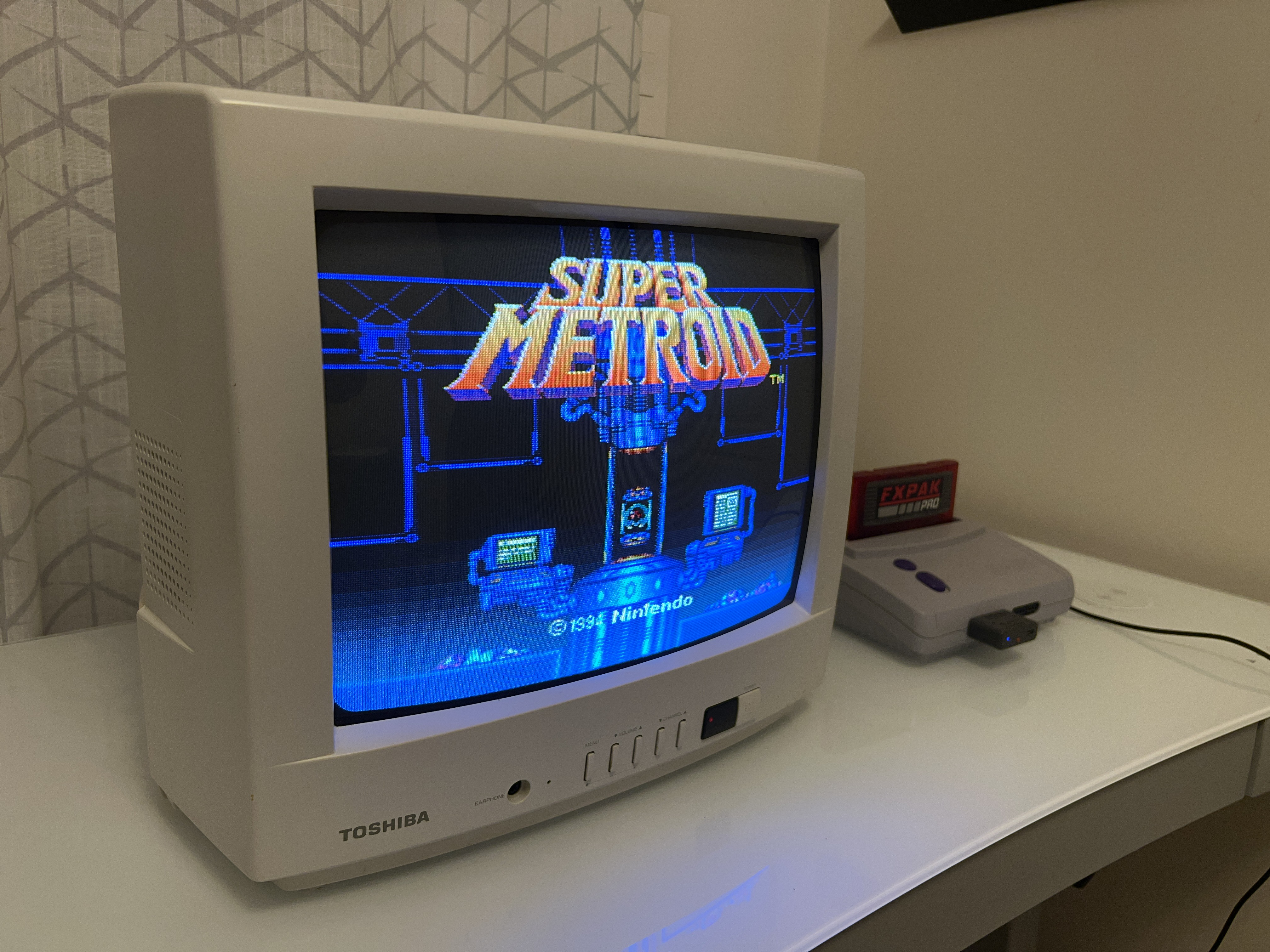
The Toshiba CF13E23 is a 13" consumer CRT television released in the late 90s as a white colored variant of the popular CF13E22 model. Unlike many later budget CRTs from Toshiba (which were rebranded models), the CF13E23 was manufactured by Toshiba.
View full CRT details and more mod examples →
Mod should also work for the below models.
- Toshiba CF13F22
- Toshiba CF19F22
This mod is also very similar to Toshiba CF19G32
Table of Contents
Contributors
Thank you to everyone who contributed to this guide:
- Sunthar — contributor, RGB mod and pictures
CRT safety
Caution
You can die doing this! So read carefully! CRT TV is not a toy. Do not open a CRT TV. If you don't have any prior knowledge about handling high voltage devices, this guide is not for you. CRT TV contains high enough voltage (20,000+ V) and current to be deadly, even when it is turned off.
Plan of attack
Manuals and Datasheets
Specs
- Manufactured: Thailand (2001)
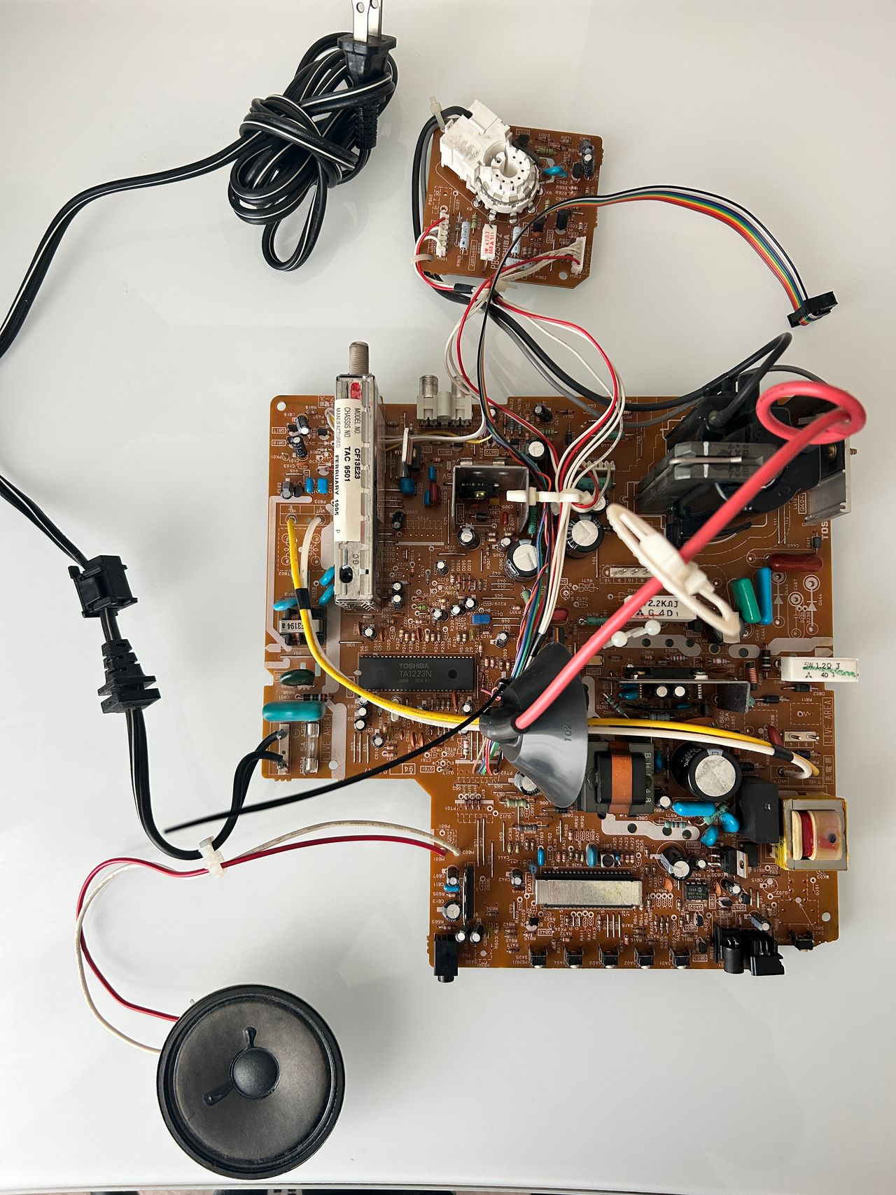
- Chassis: TAC 9501
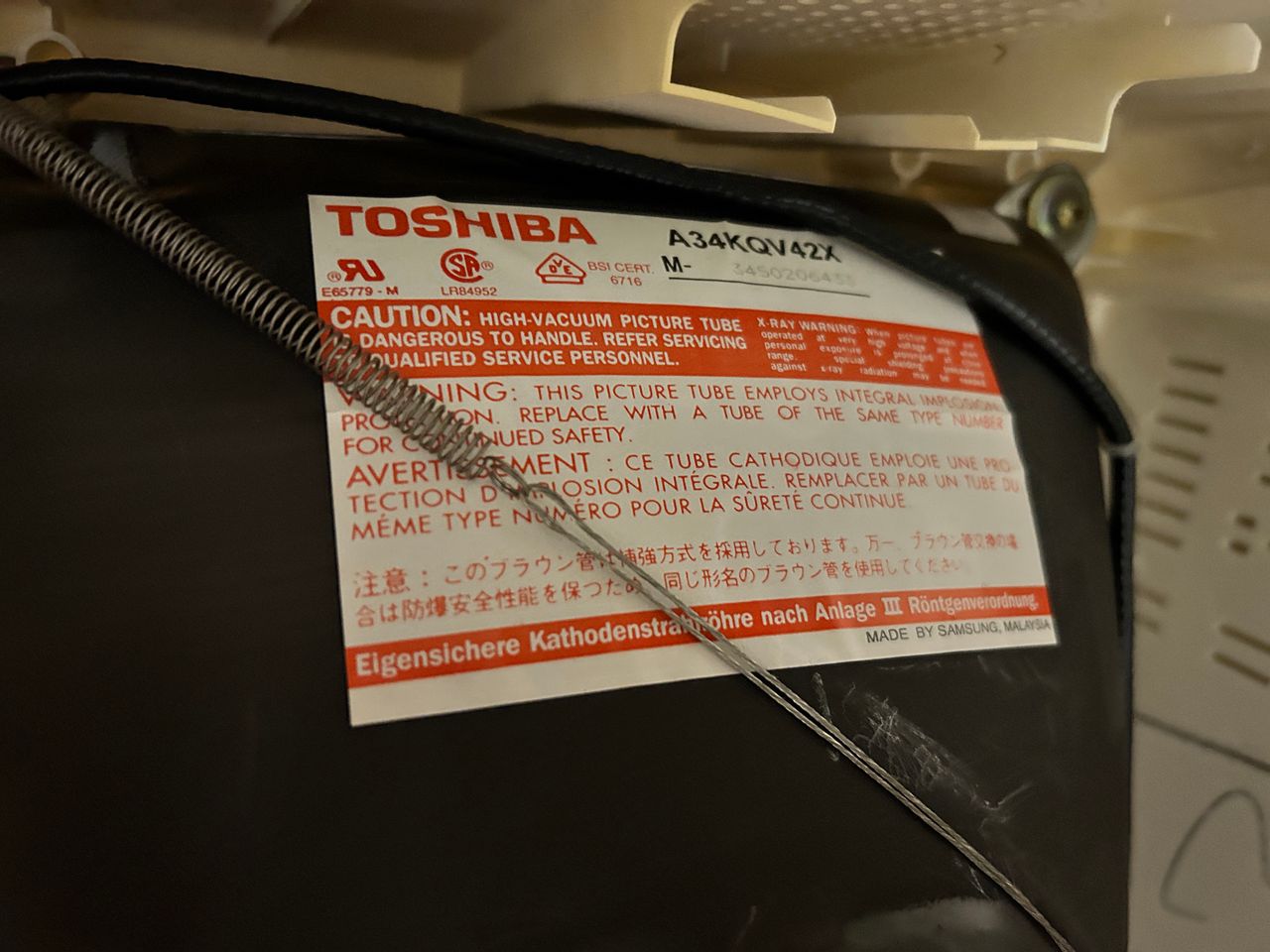
- Tube: Toshiba A34KQV42X
- Jungle Chip: Toshiba TA1223N
- OSD Chip: TMP87CM34BN-3298
- Screen Size: 13"
- Power: 43 W
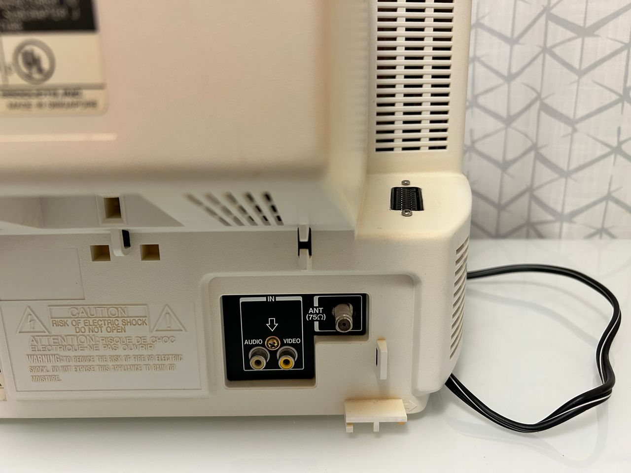
- Inputs: Composite
Schematics
Get hold of the schematics for your TV. Understand where the RGB and Fast Blanking signals go from OSD to the Jungle (Chroma) chip.
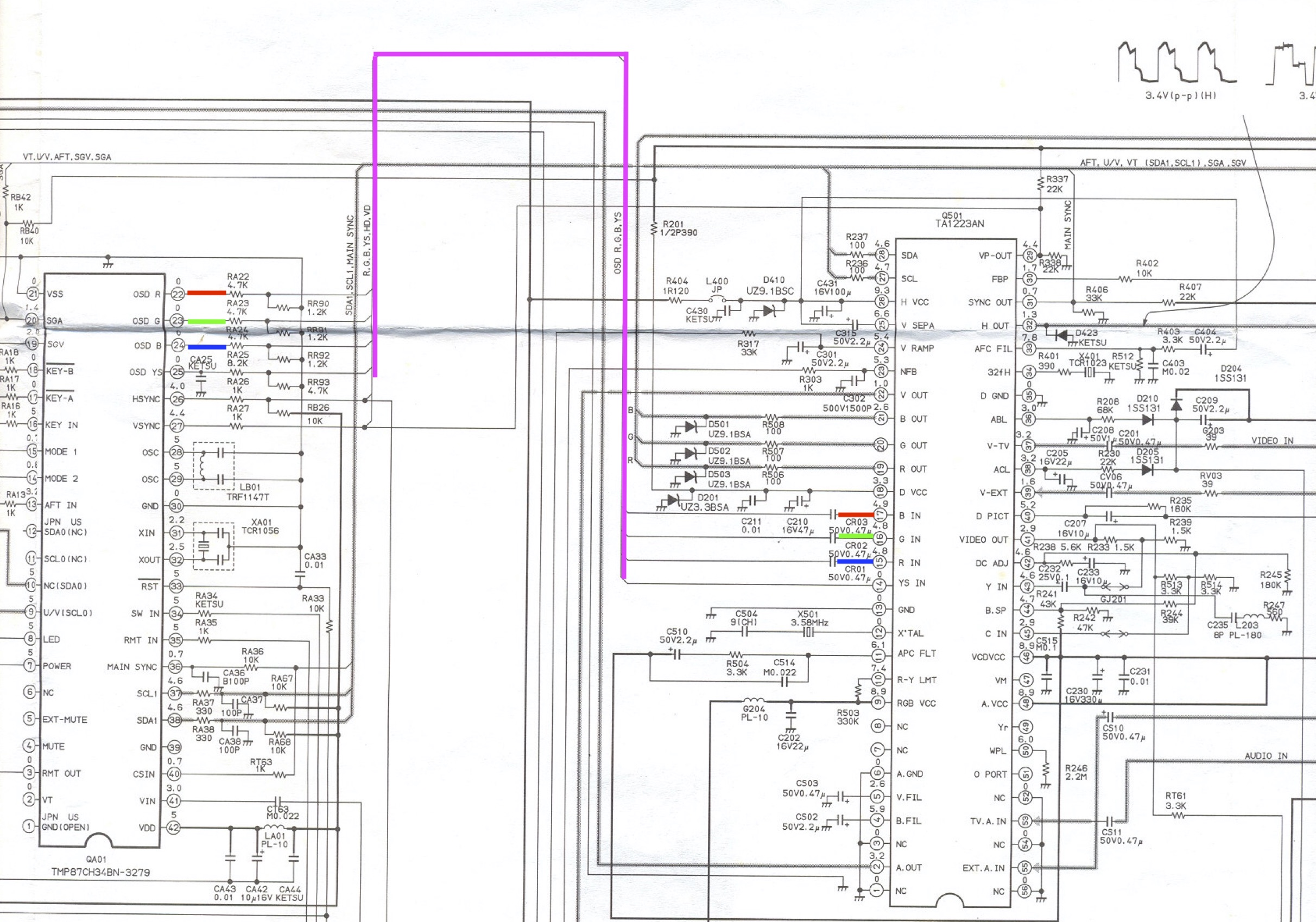
RGB mux diagram
Prepare the mux diagram. If you are building your own circuit, this diagram should help.
Performing the mod
We are going to focus in the below three areas first - A, B and C.
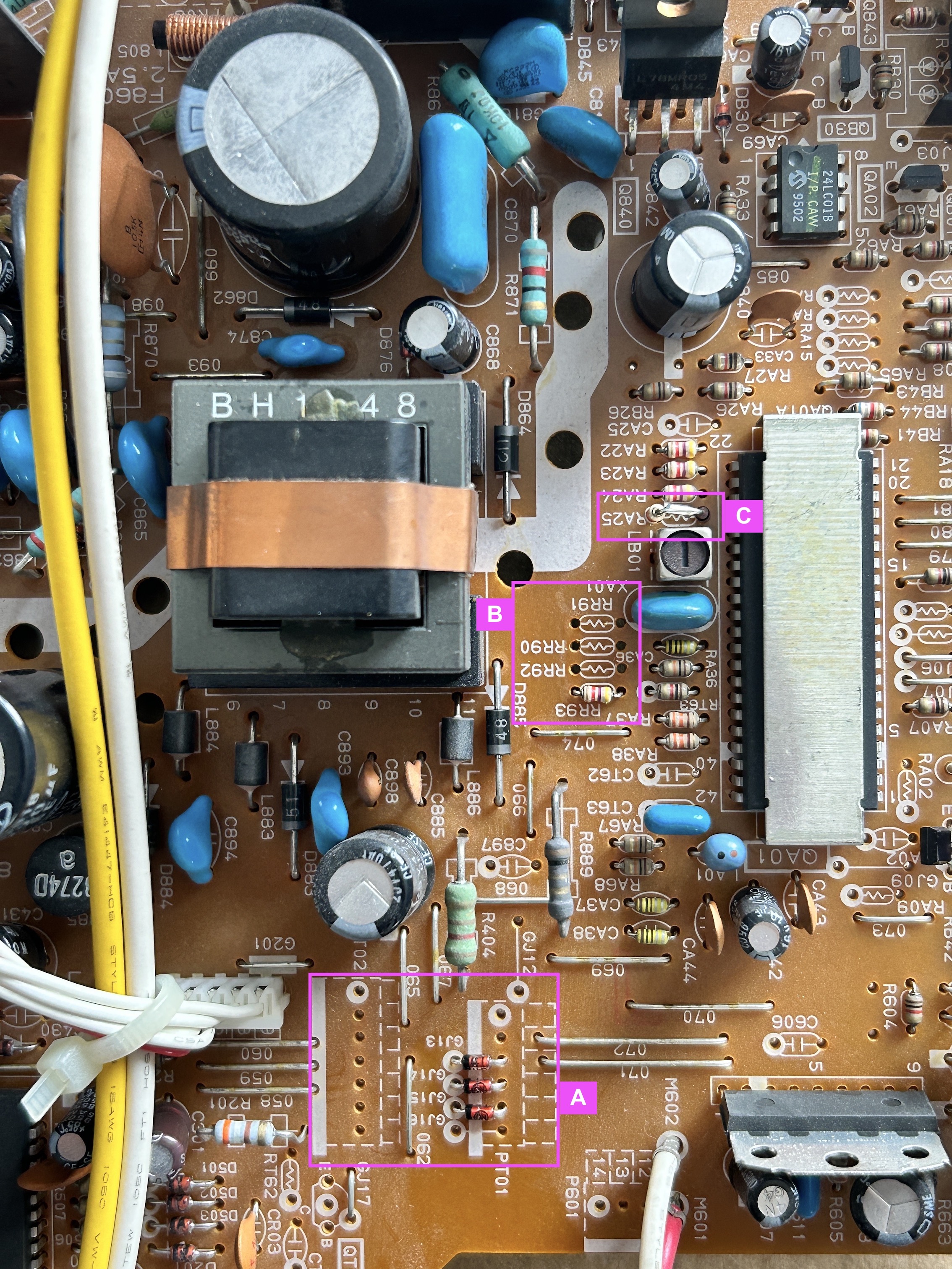
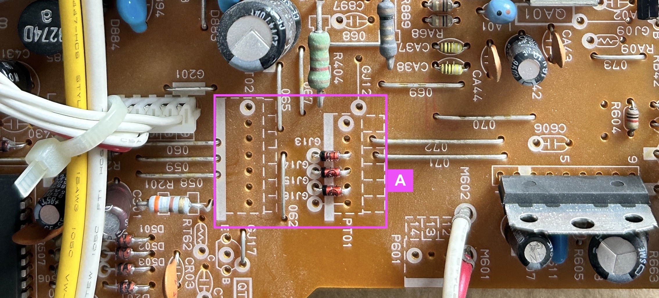
STEP 1: Cut traces and install diodes (Area A)
Cut traces as seen below. This allows us to install diodes in vias that already exist on this chassis.
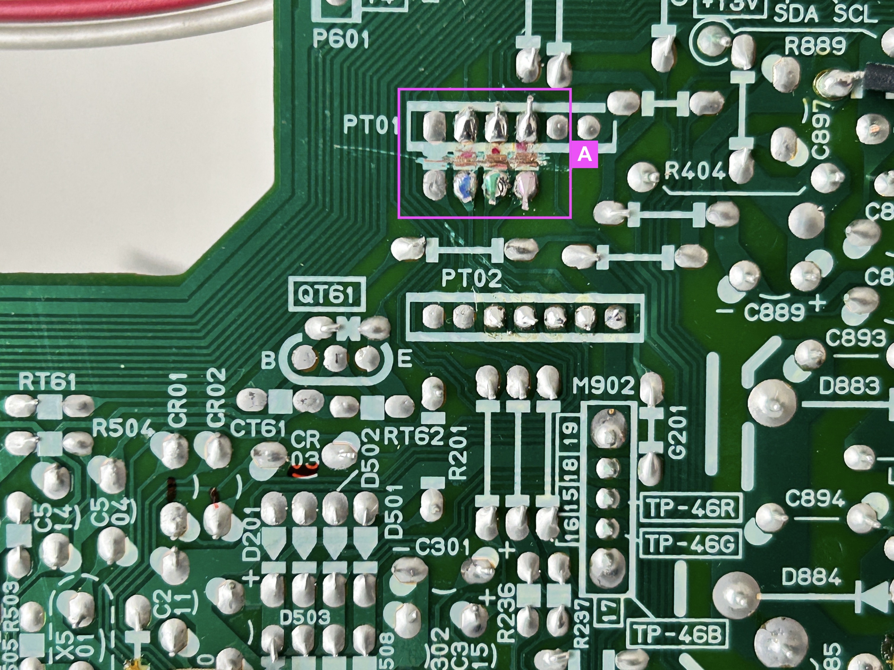
See Area A. We are going to install RGB inline diodes (1N4148) on the component side of the board where we cut the traces. Pay attention to the direction of the diodes. This will prevent the current from going into the OSD, creating a reflection in signal, that causes interference.
STEP 2: Remove the following resistors (Area B)
Remove the three 1.2 kΩ, RGB resistors to ground
- RR90
- RR91
- RR92

STEP 4: Install an inline diode for blanking (Area C)
This is an important step to remove interference. On 13" sets, this interference is barely noticeable. On 19" sets, you can in most cases see this interference.
![]()
Pay attention to the direction of the diode stripe. Stock 8.2 kΩ resistor was replaced with 6.8 kΩ resistor.
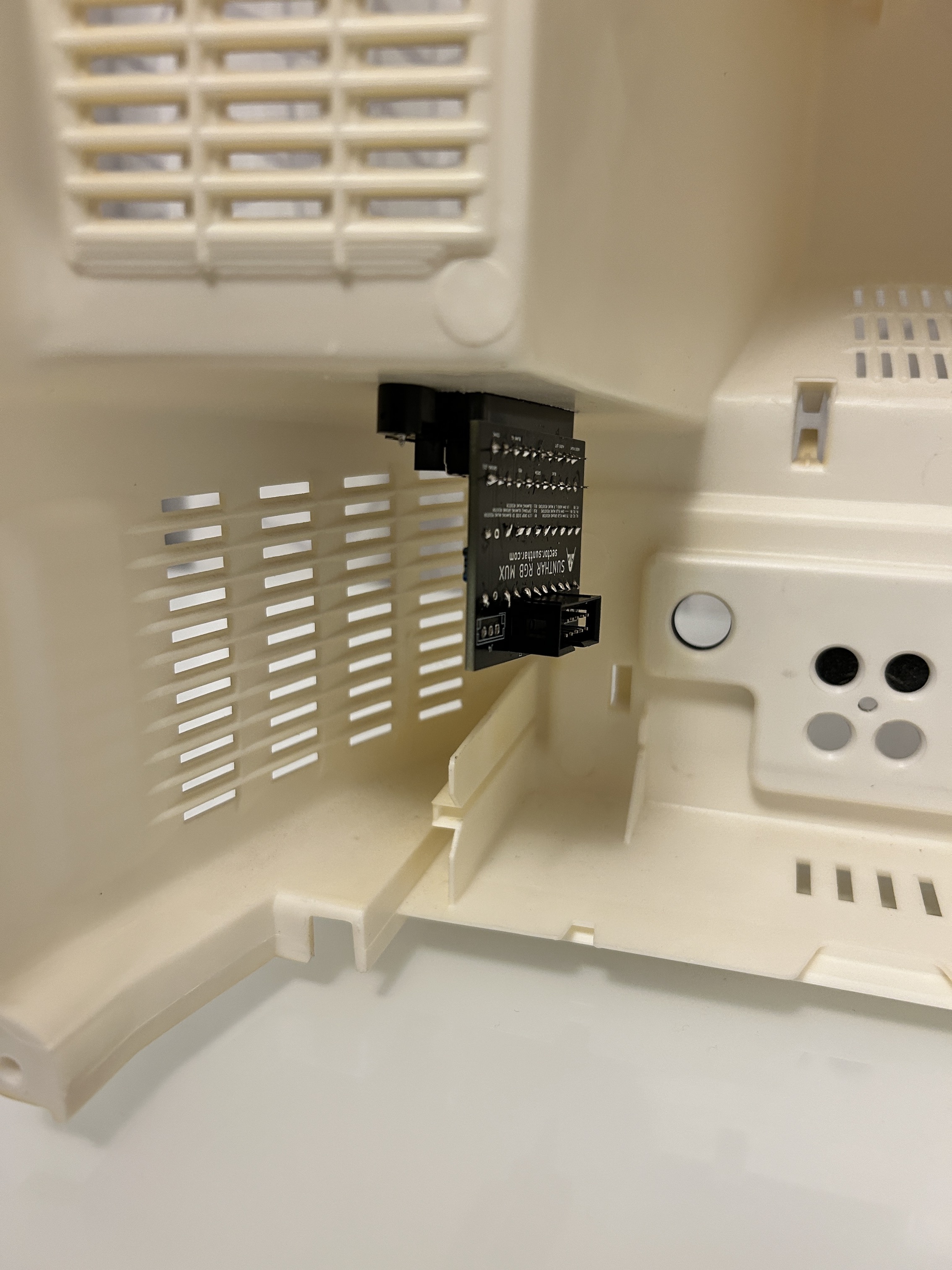
STEP 5: Connect RGB, blanking and ground
There are convenient vias where the R (red), G (green), B (blue), Blanking (brown) and Ground (black) wires should be connected.
![]()
STEP 6: Hook up sync and Audio
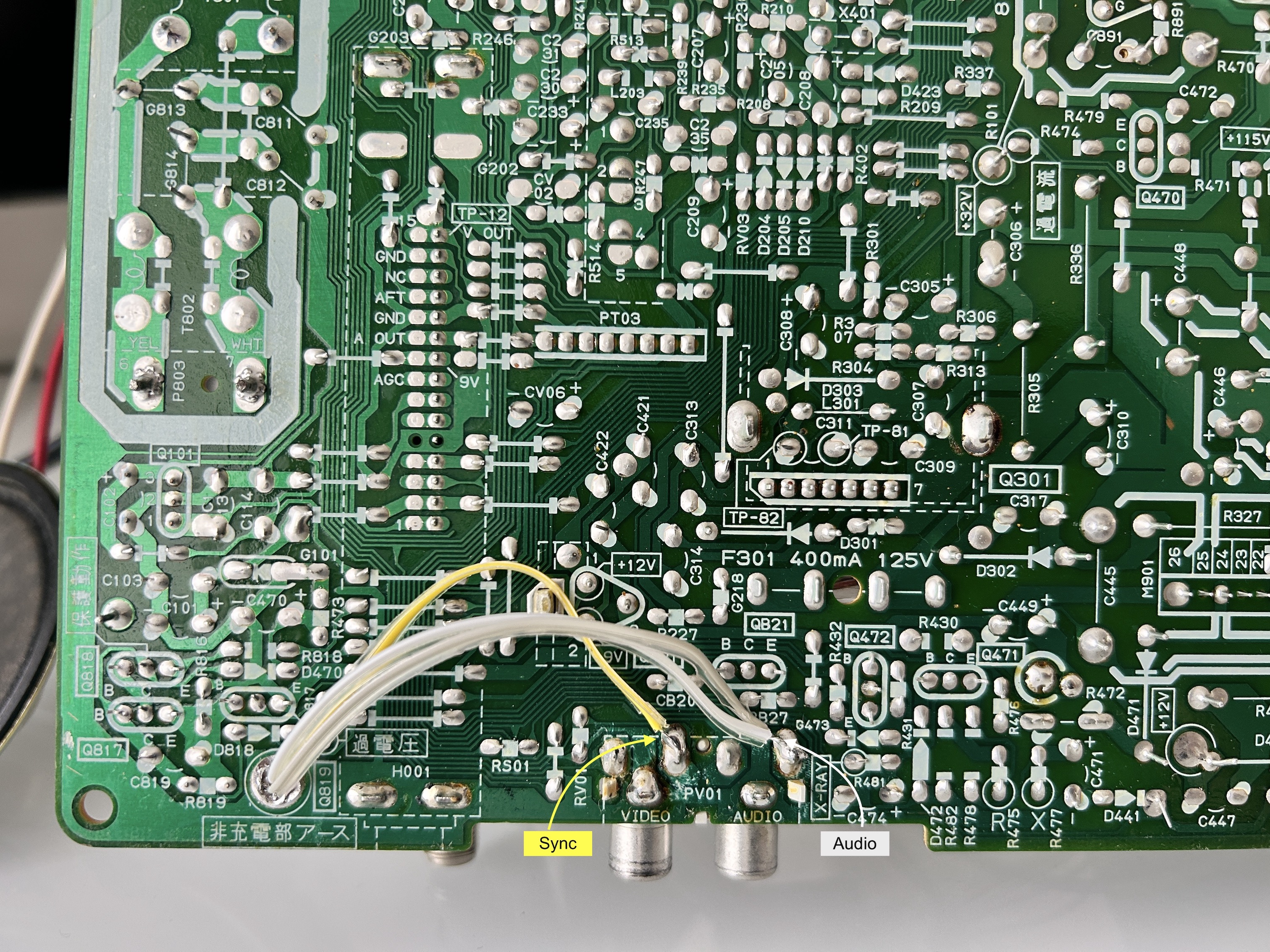
Purple and orange wires in the latest 1.2B/1.2C boards are auxillary. You can leave them disconnected.
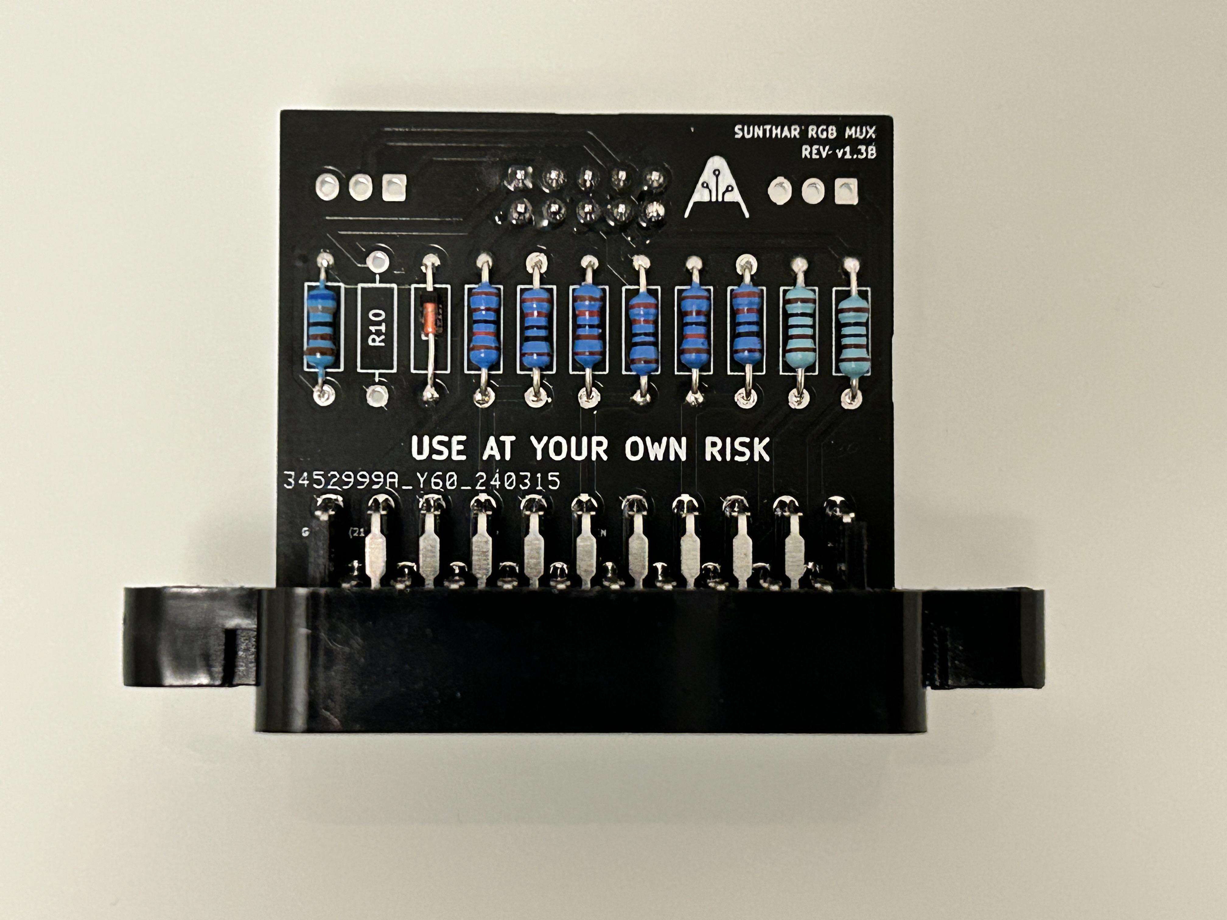
STEP 7: Build your mux circuit
I had to use a RGB tuner gadget I made to find the right balance for RGB termination. It was found using a 150Ω to 180Ω resistor gave the best vibrancy of colors.
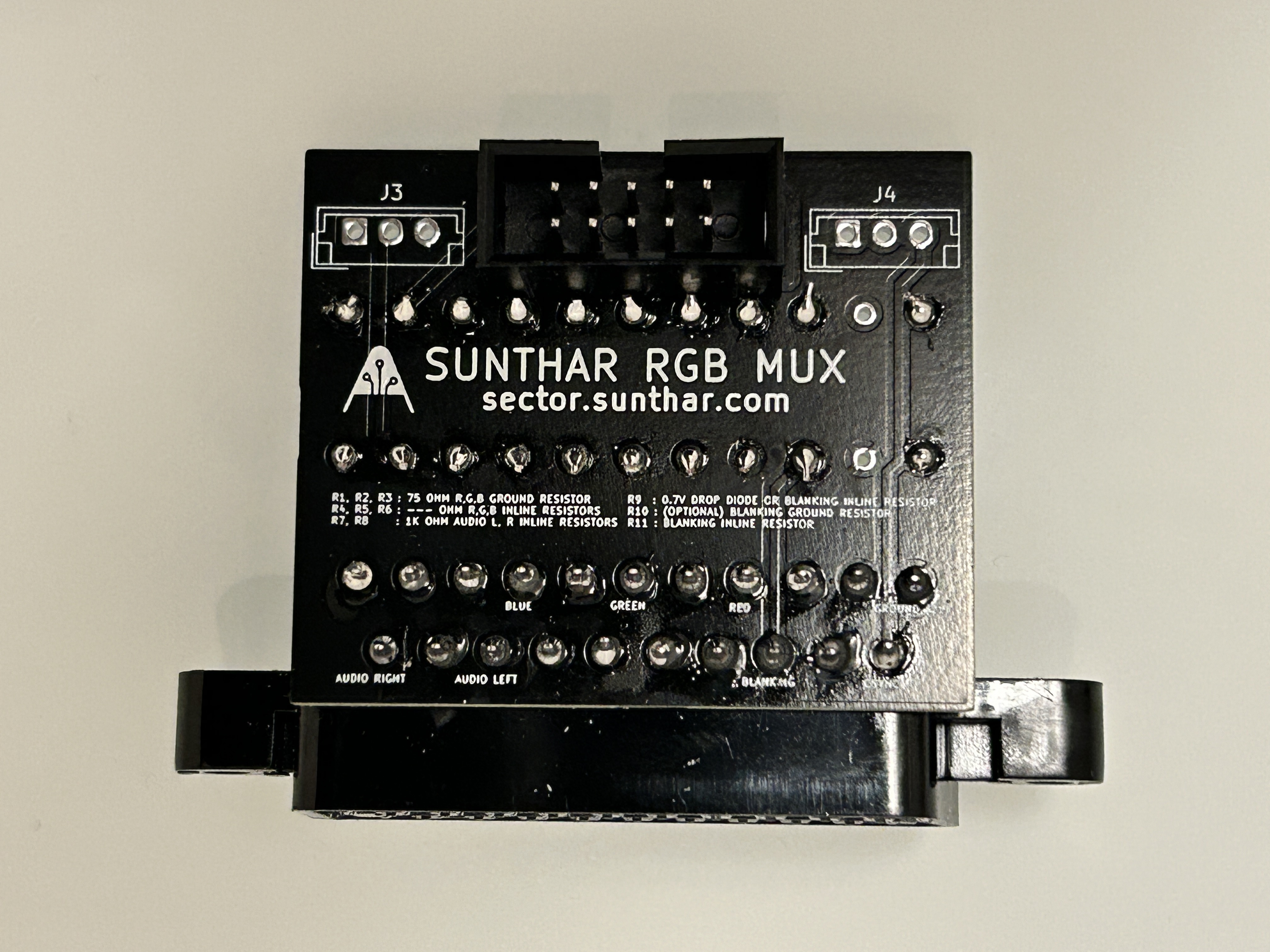
This mod uses the RGB mux board. This is optional, but will make your mod easier and stable. You can also create the circuit presented in the schematics above without the board. Please also checkout the mux calculator to play with your own values.
| On Toshiba CRT Chassis | CF13E23 |
|---|---|
| CRT RGB inline resistor | 4.7kΩ |
| CRT RGB ground resistors removed | 1.2kΩ |
| 0.1μF caps replaced | No |
| Add diodes on chassis RGB lines? | Yes |
| Add blanking diode on chassis | Yes |
| Replace blanking resistor on chassis | 6.8kΩ |
| RGB mux board | CF13E23 |
|---|---|
| Mux board RGB termination (R1, R2, R3) | 180Ω |
| Mux board RGB inline resistors (R4, R5, R6) | 1.2kΩ |
| Mux board Audio LR (R7, R8) | 1kΩ |
| Mux board blanking diode (R9) | 1N4148 |
| Mux board blanking ground resistor (R10) | open |
| Mux board blanking resistor (R11) | 6.8kΩ |
Note: R4, R5 and R6 can also be 1kΩ. 180Ω is used to spice up the RGB signal. 75Ω should just work fine.
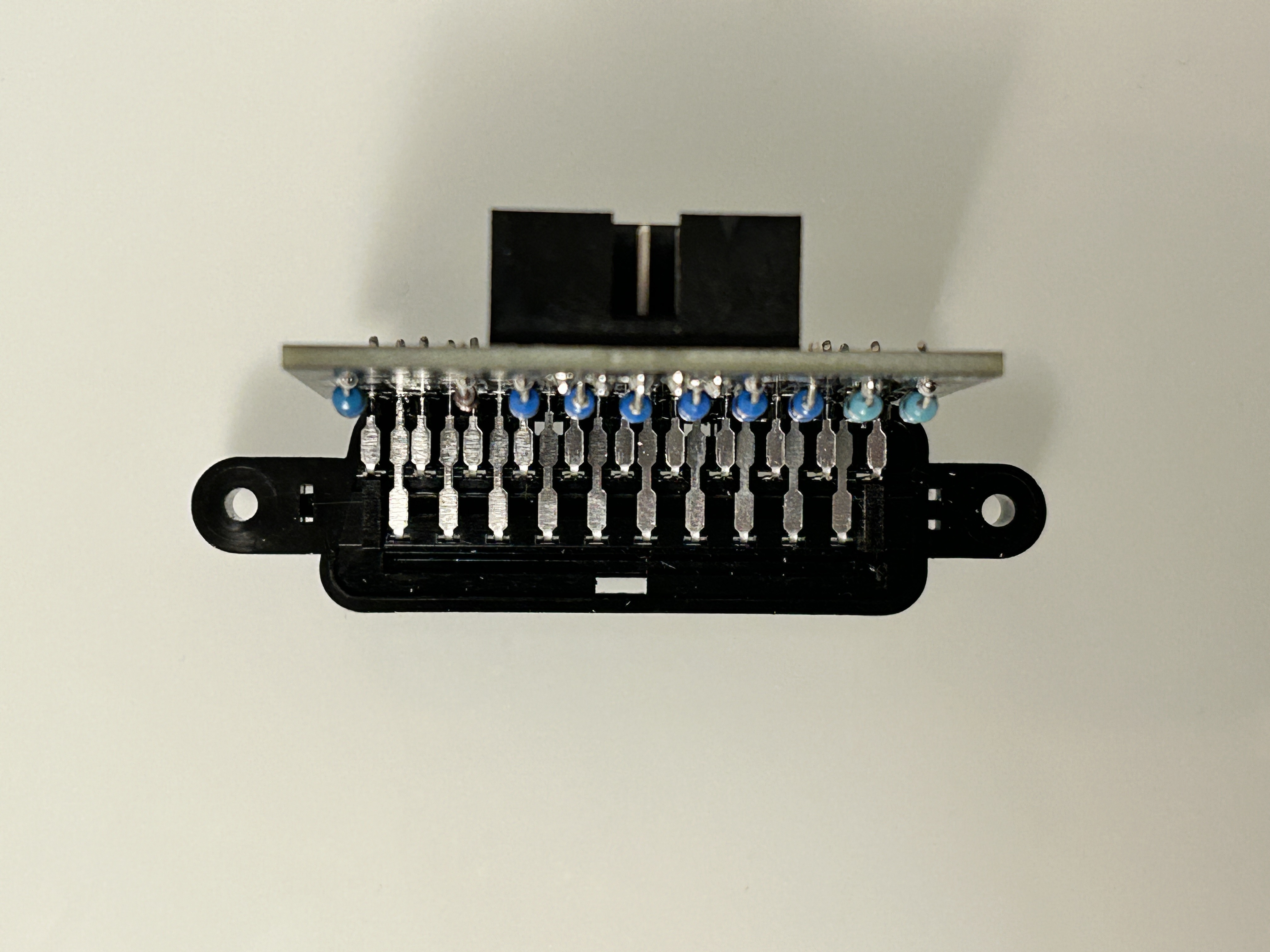
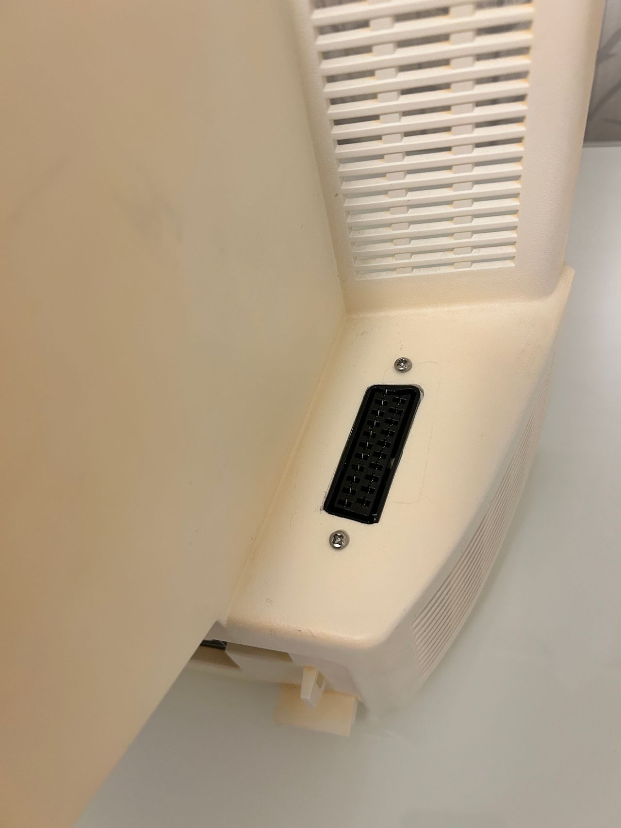
STEP 6: Attach the female SCART connector to TV
Creating a SCART cutout and mounting it is an art. I have a dedicated section for it.

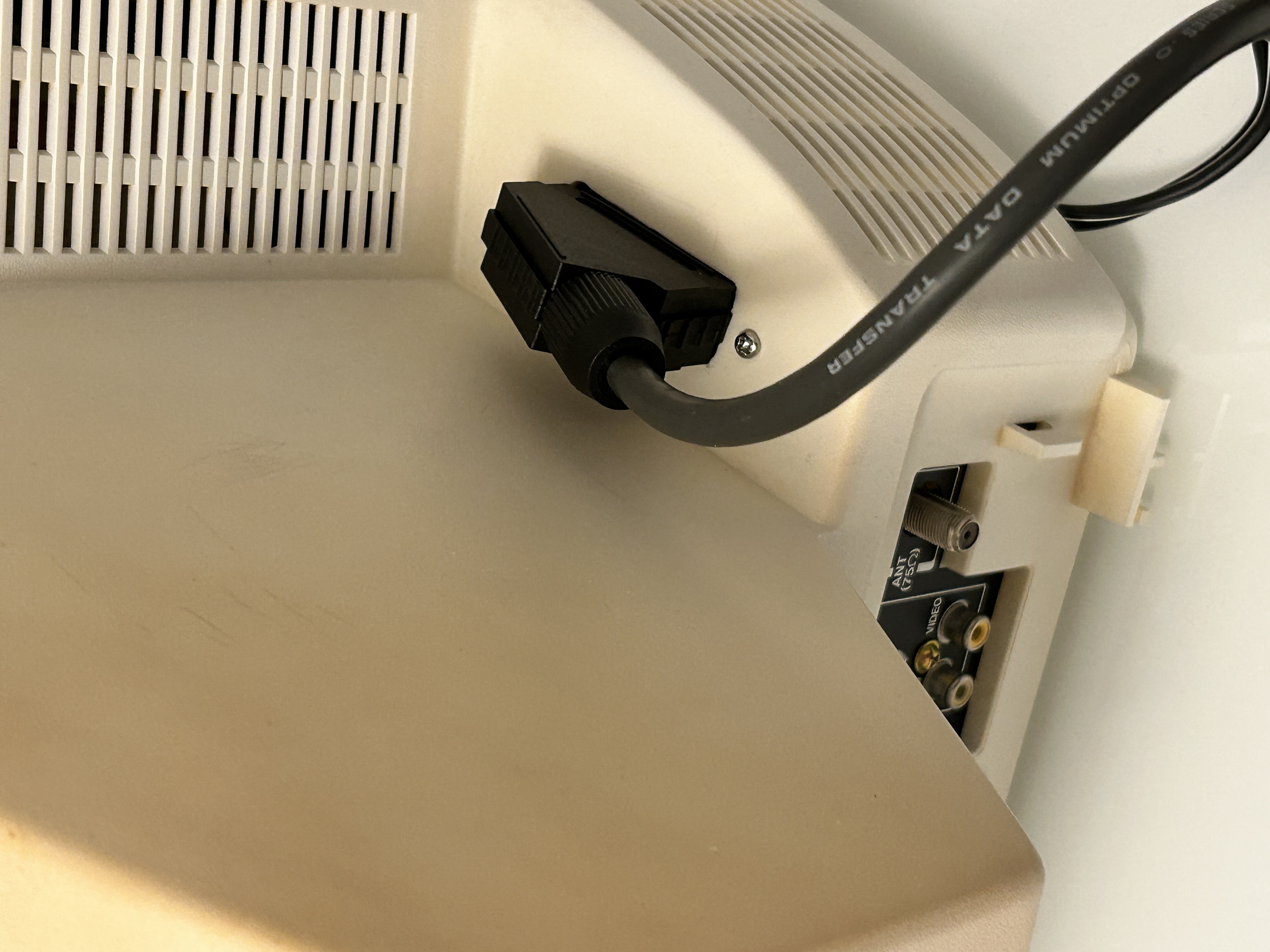
How to create and mount a SCART female plug?
OSD Overlay
Games
NES - Adventure Island 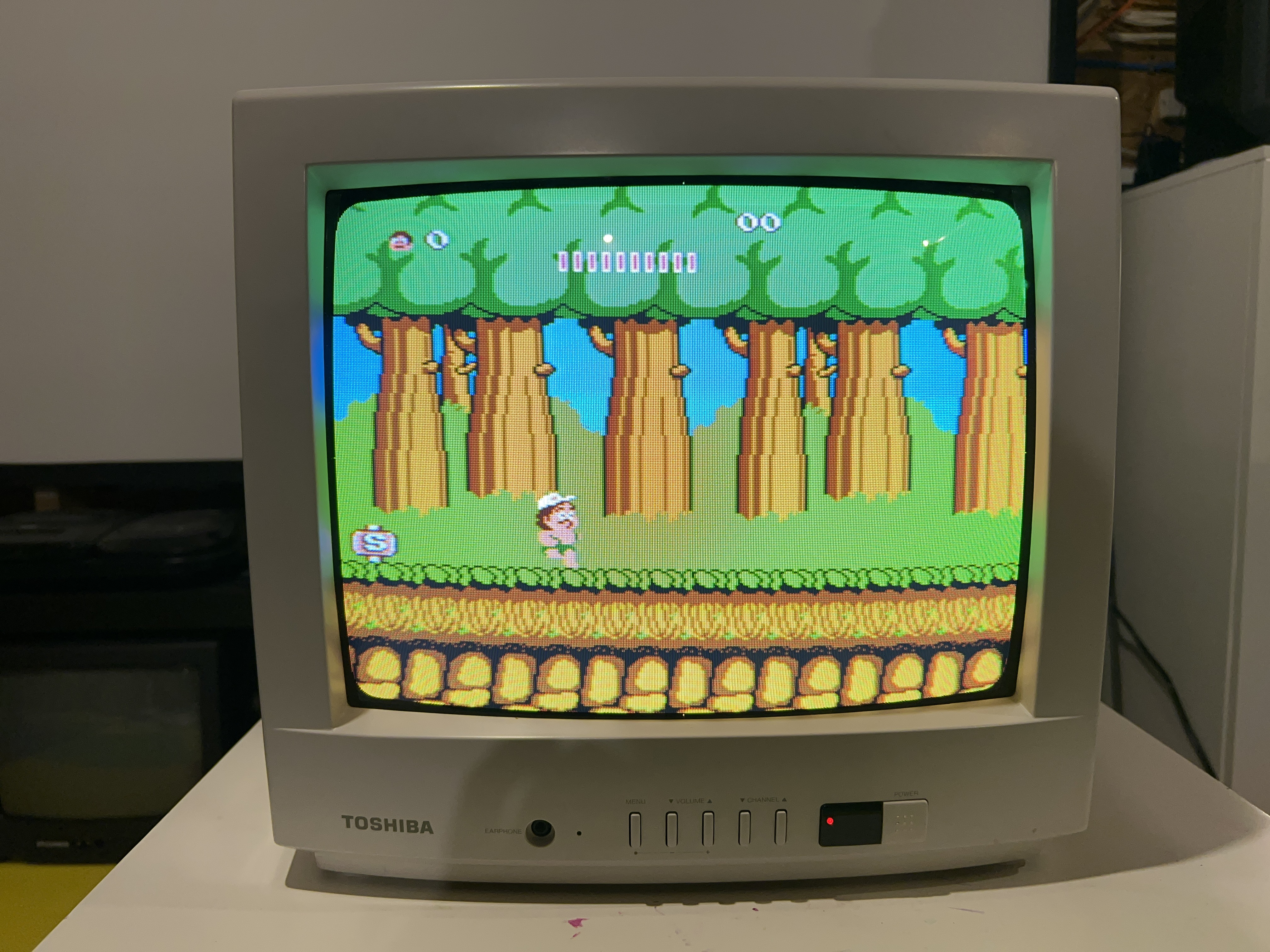
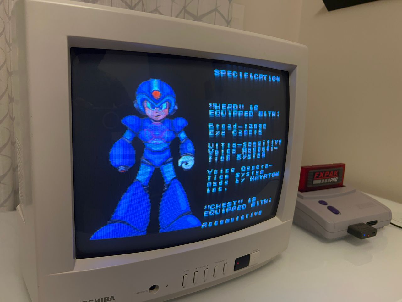
SNES - Mega Man X 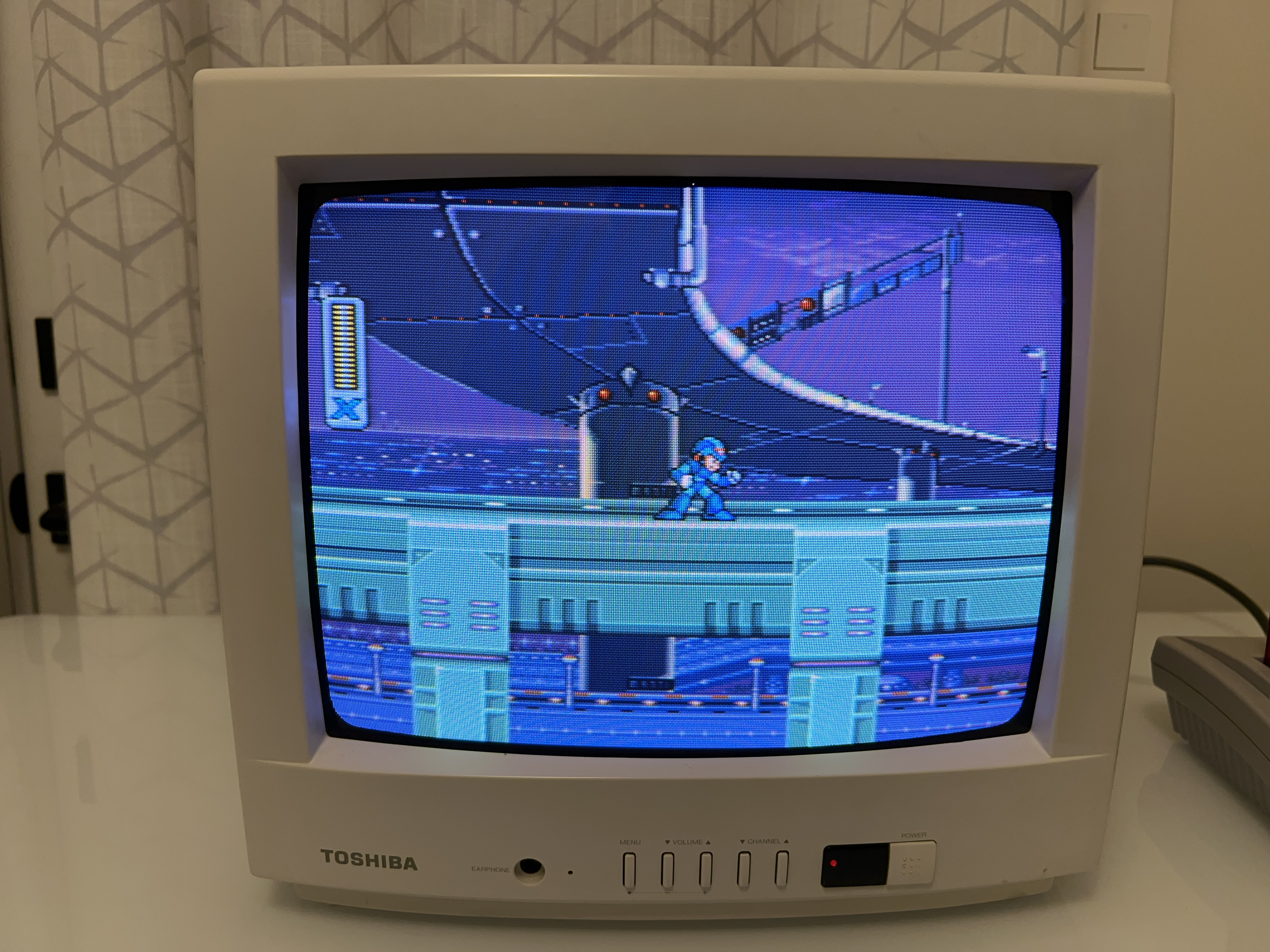
SNES - Yoshi's Island 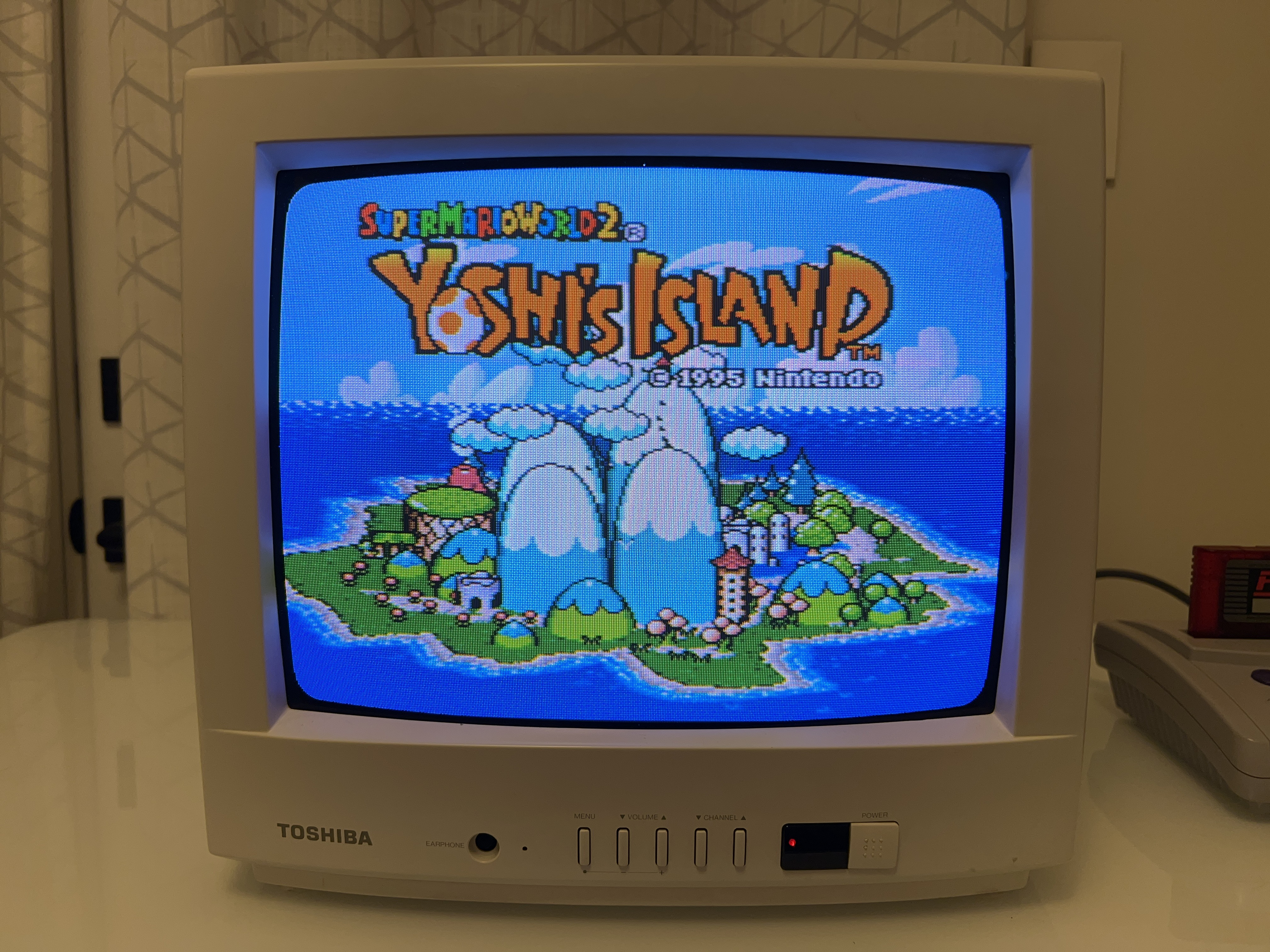
SNES - Yoshi's Island (Close up) 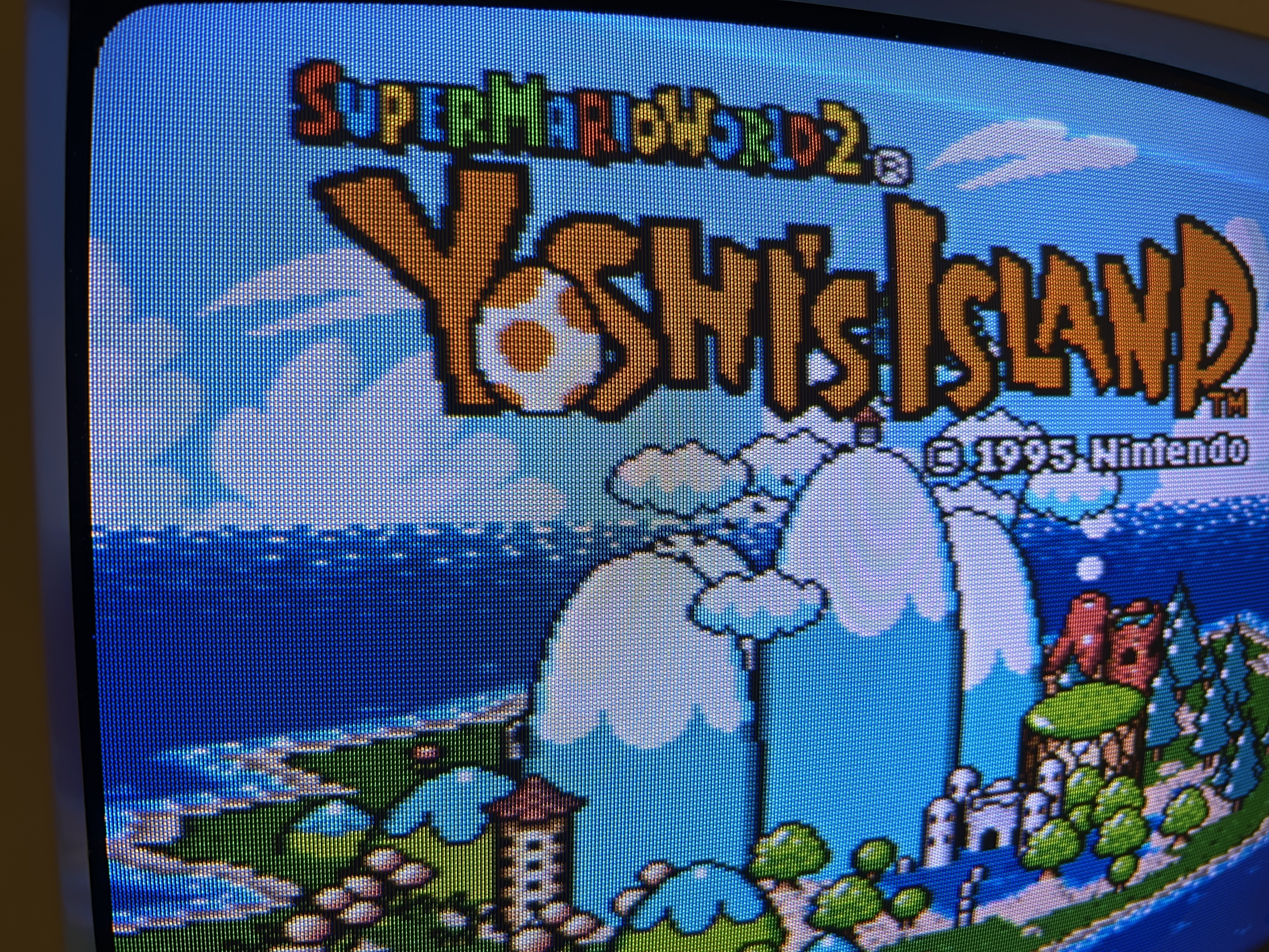
SNES - Super Mario World (Close up) 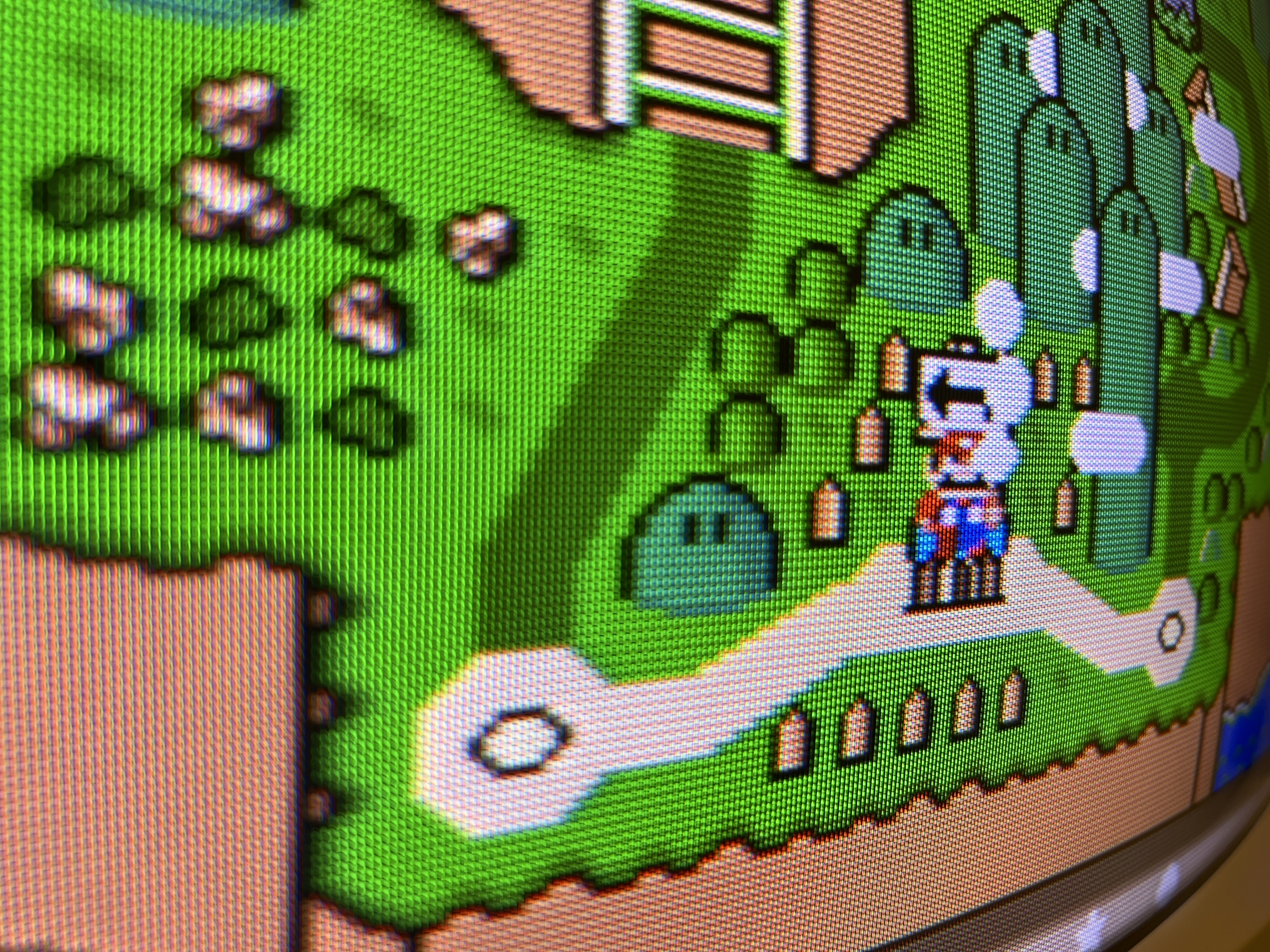
Sega Genesis - Sonic 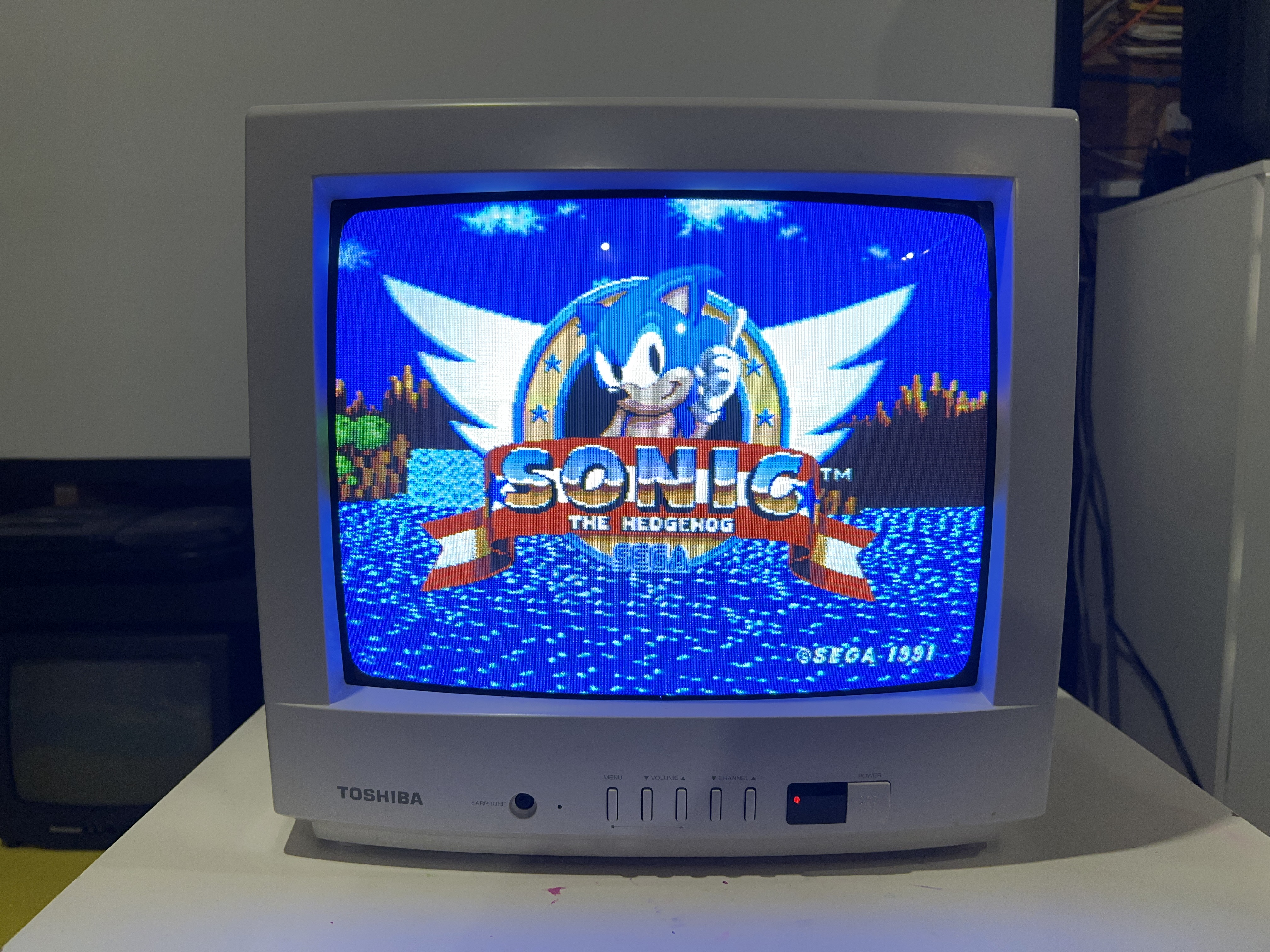
Playstation - Boot 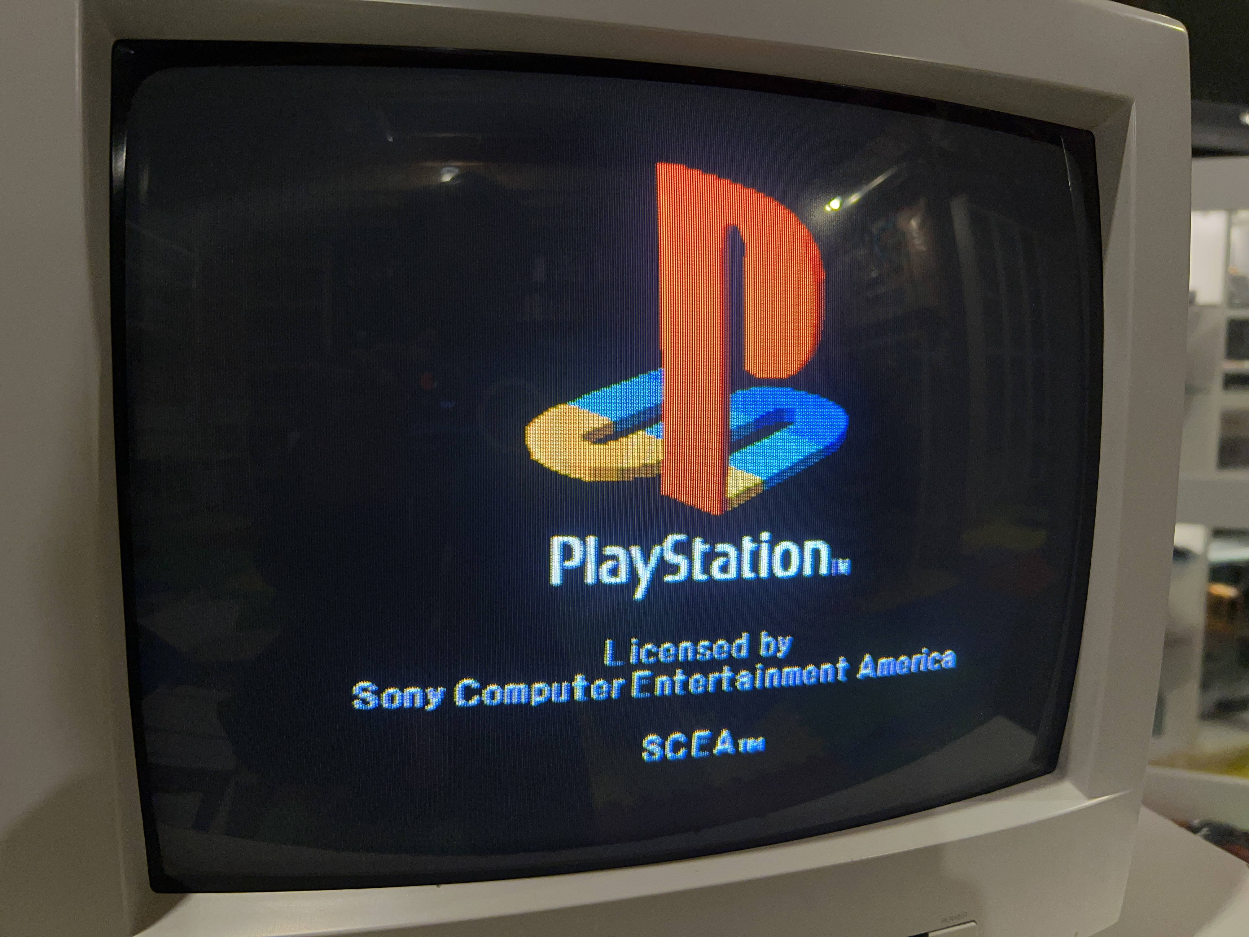
Patterns
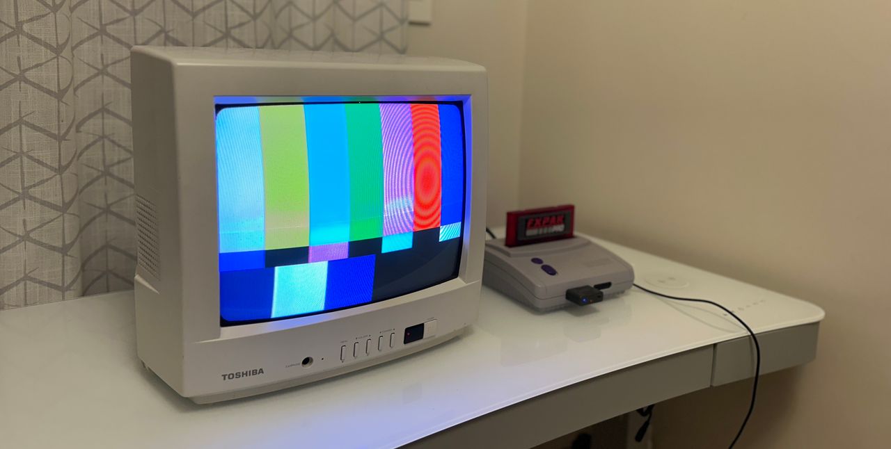
240p - Monoscope 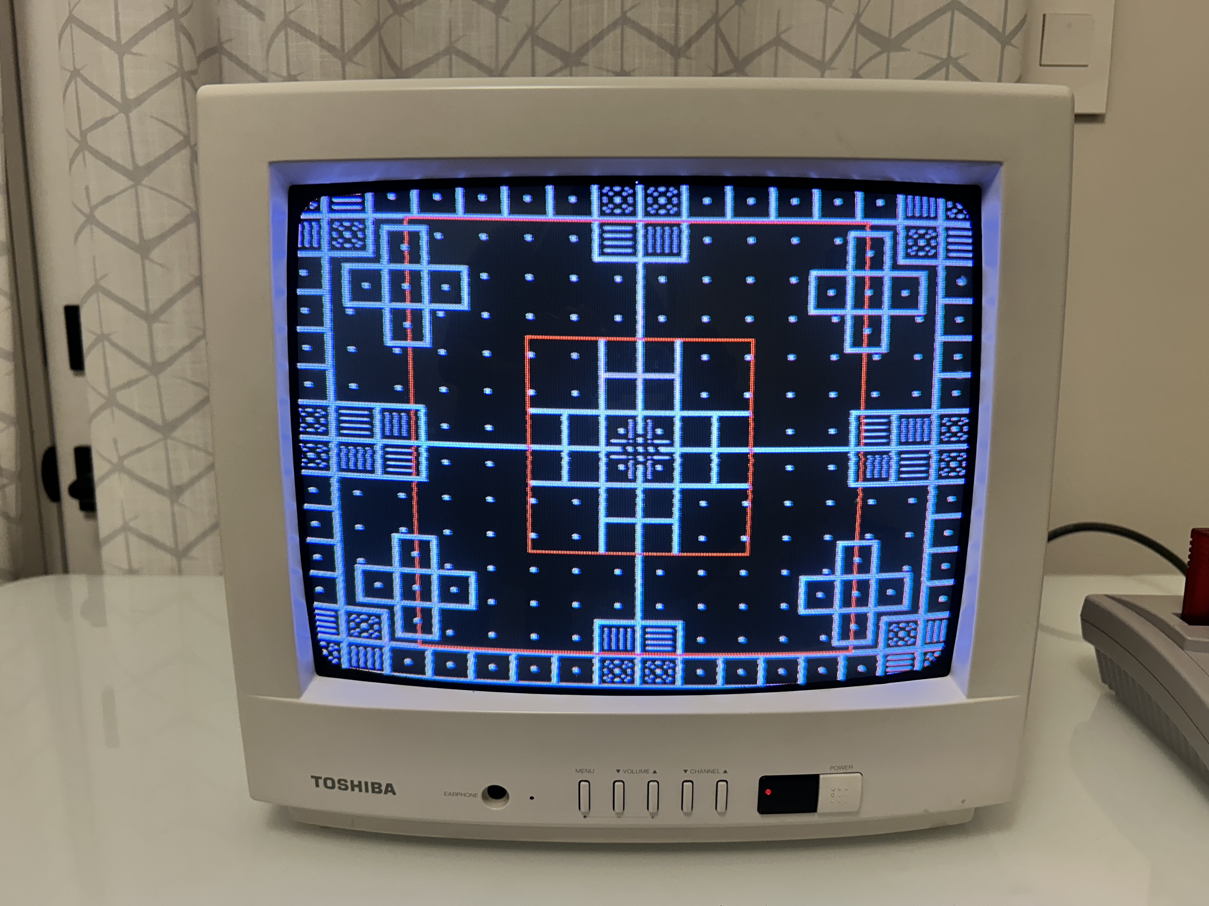
240p - RGB 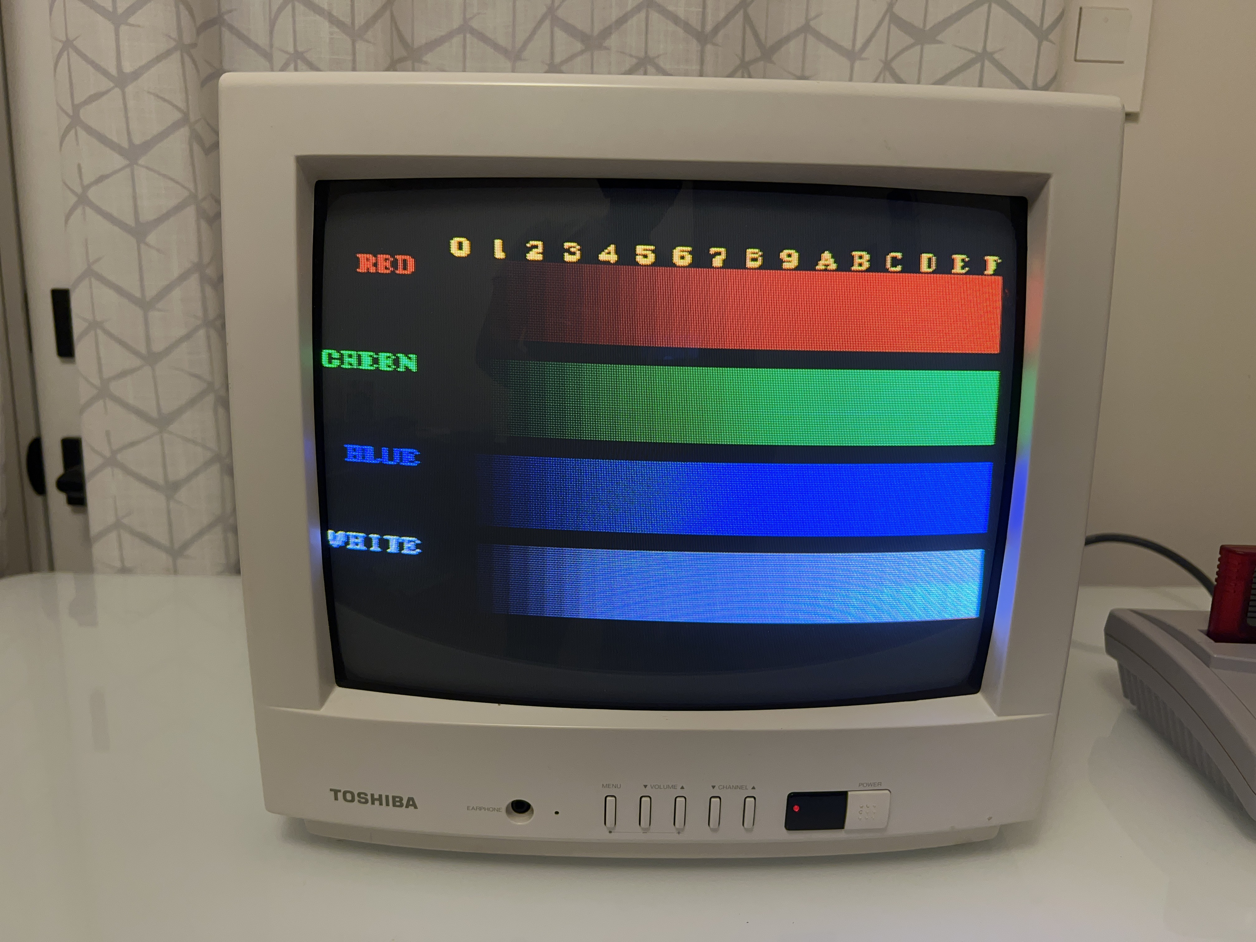
240p - SMPTE 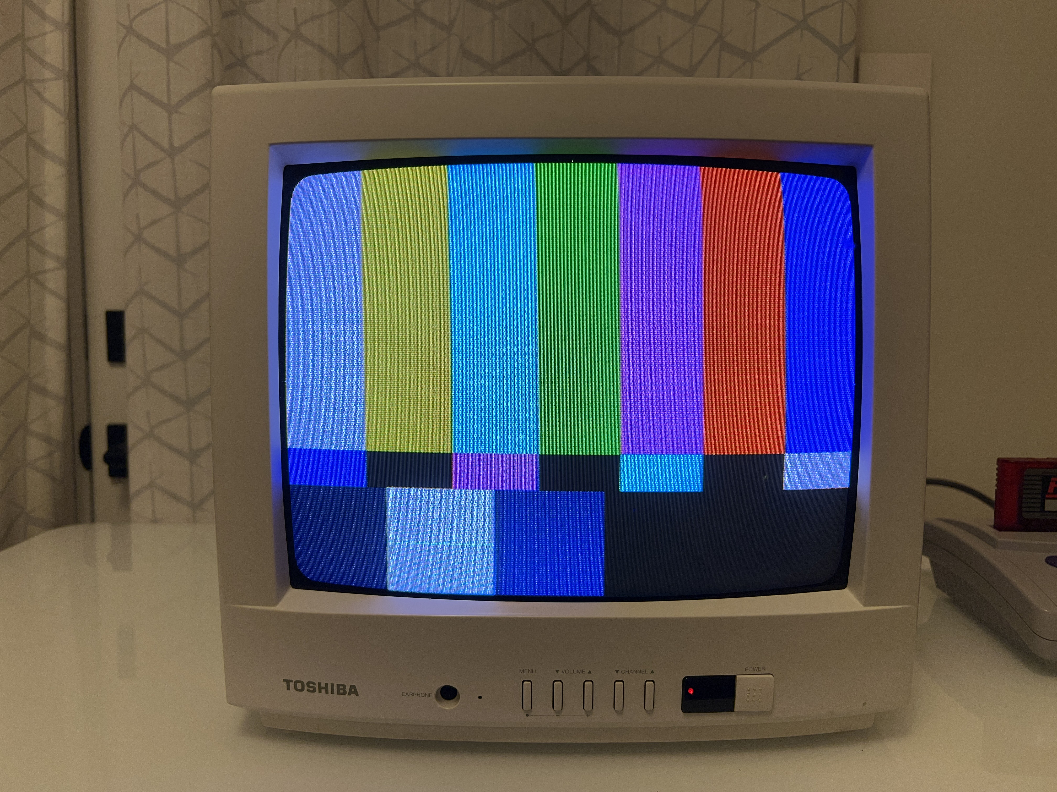
240p - Convergence 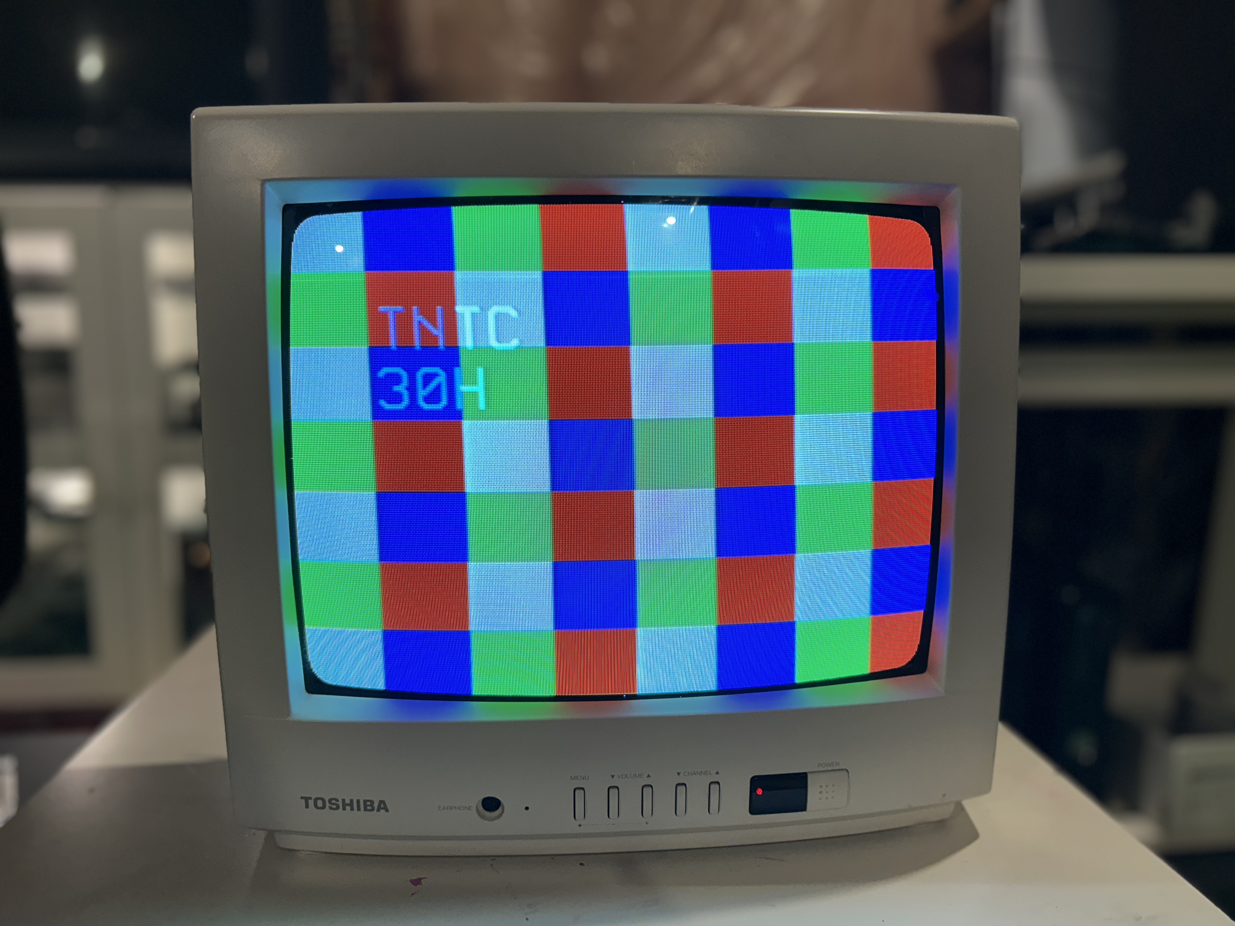
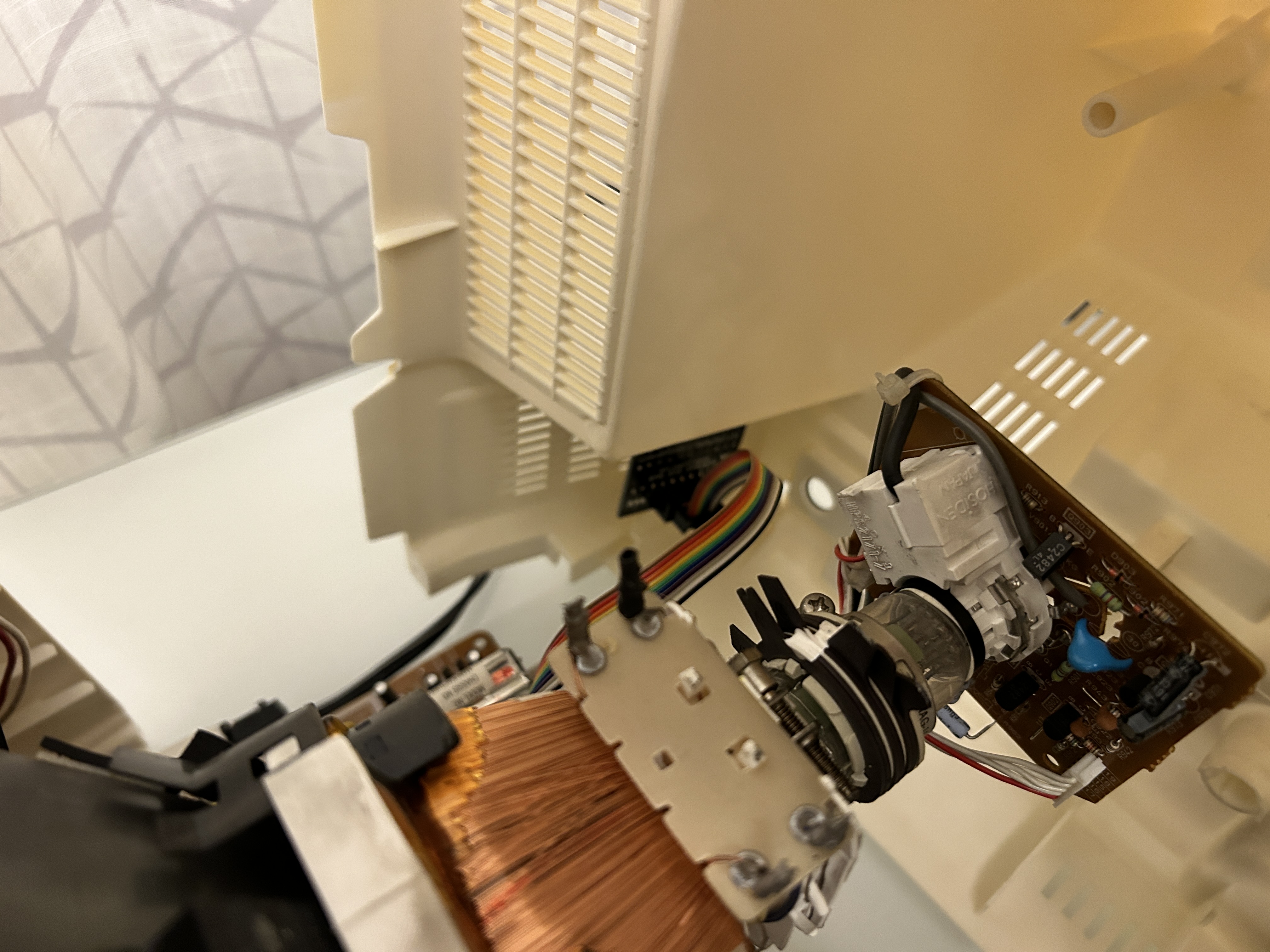
TV
Chassis 
Chassis Back 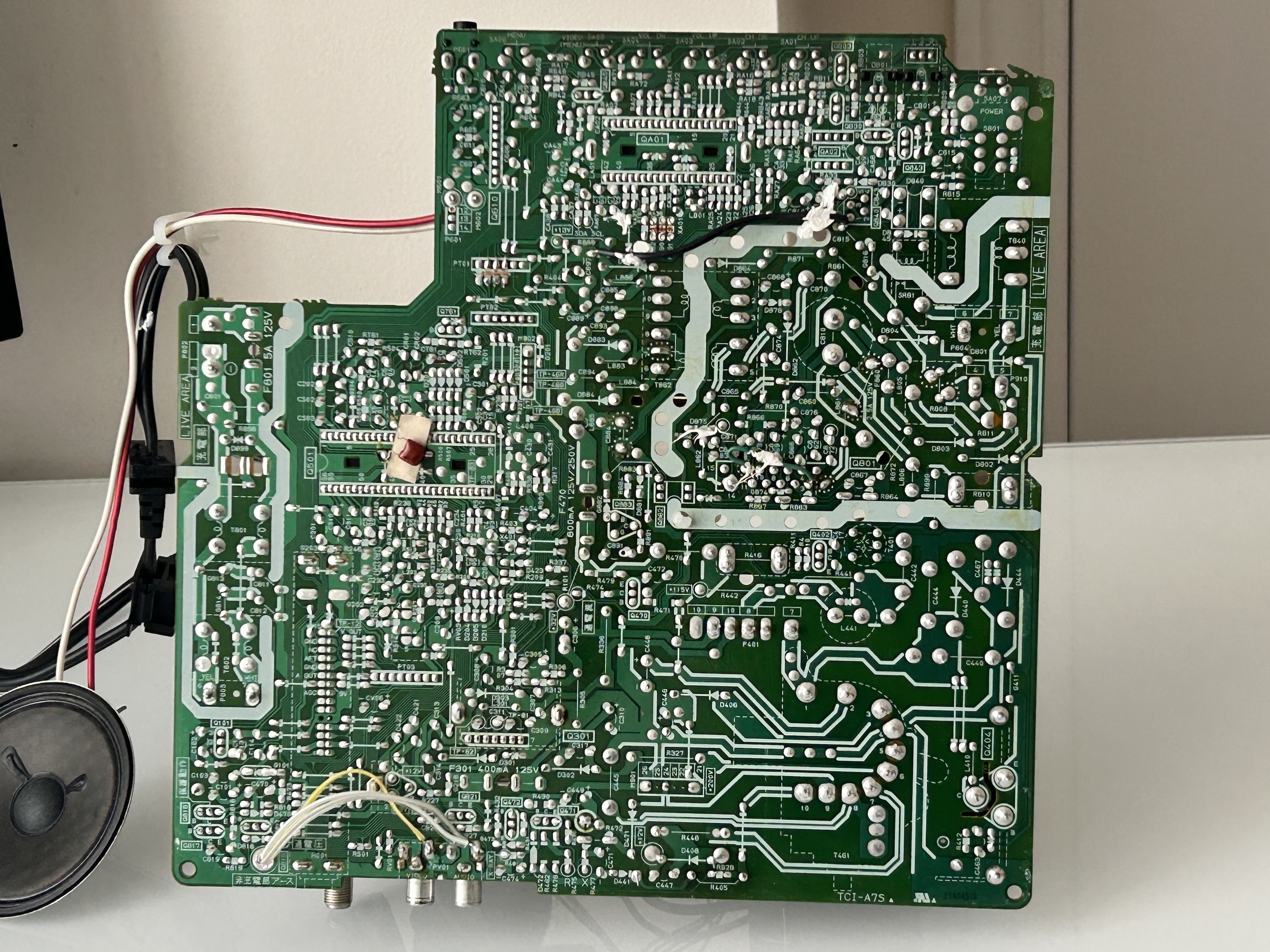
Flyback 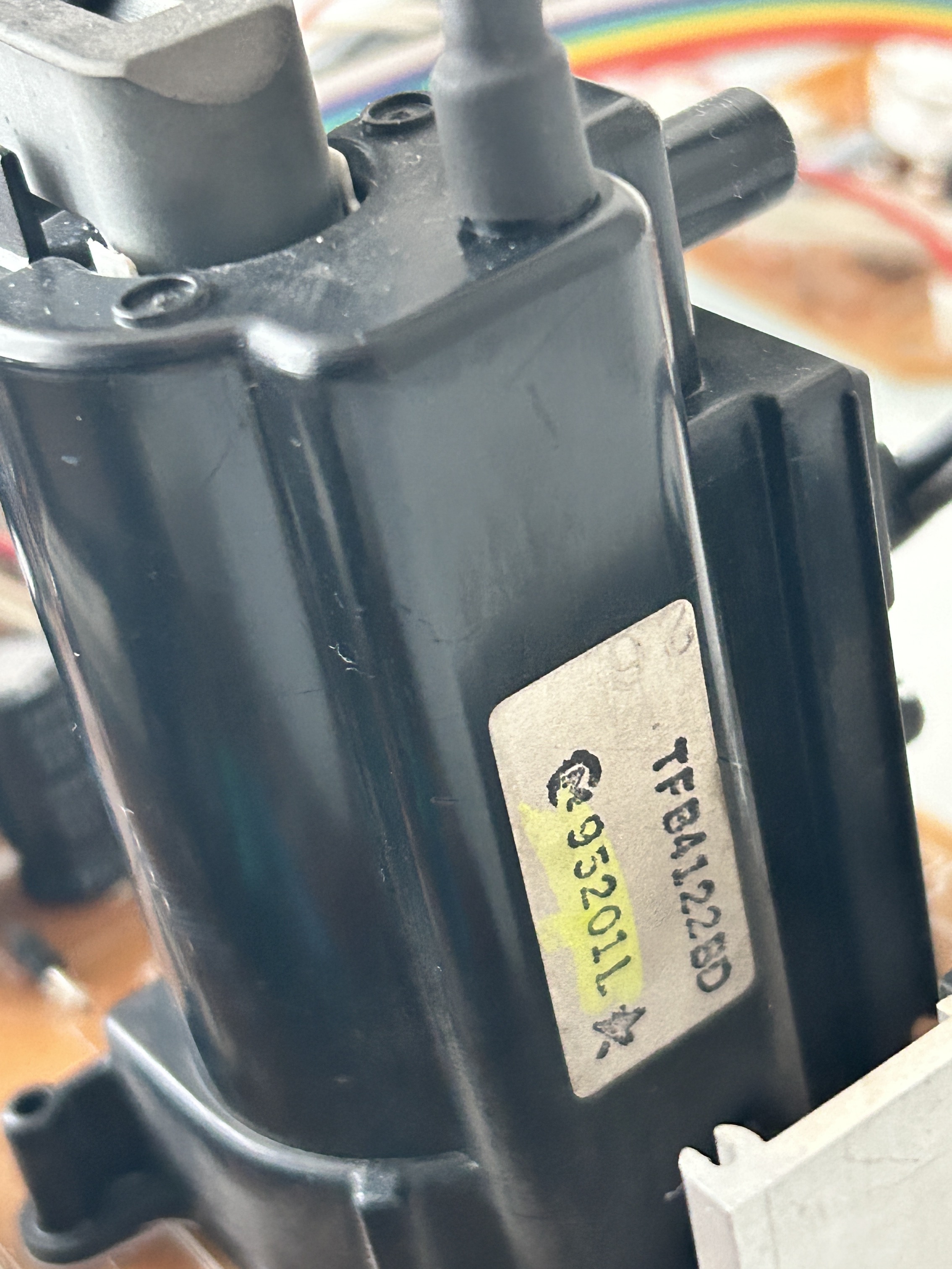
Tube 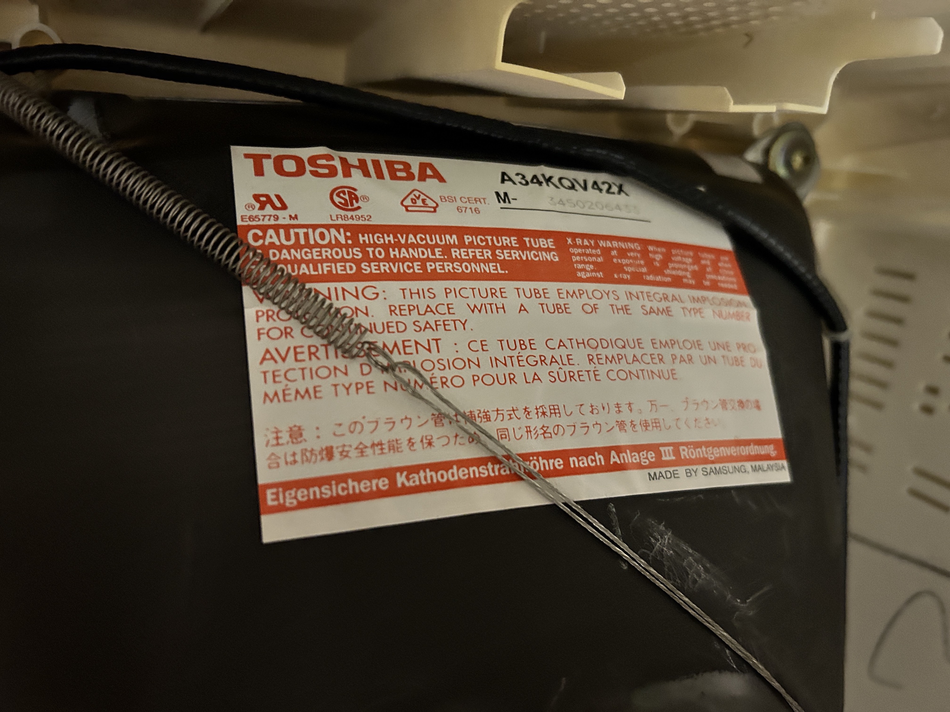
Label 
Label 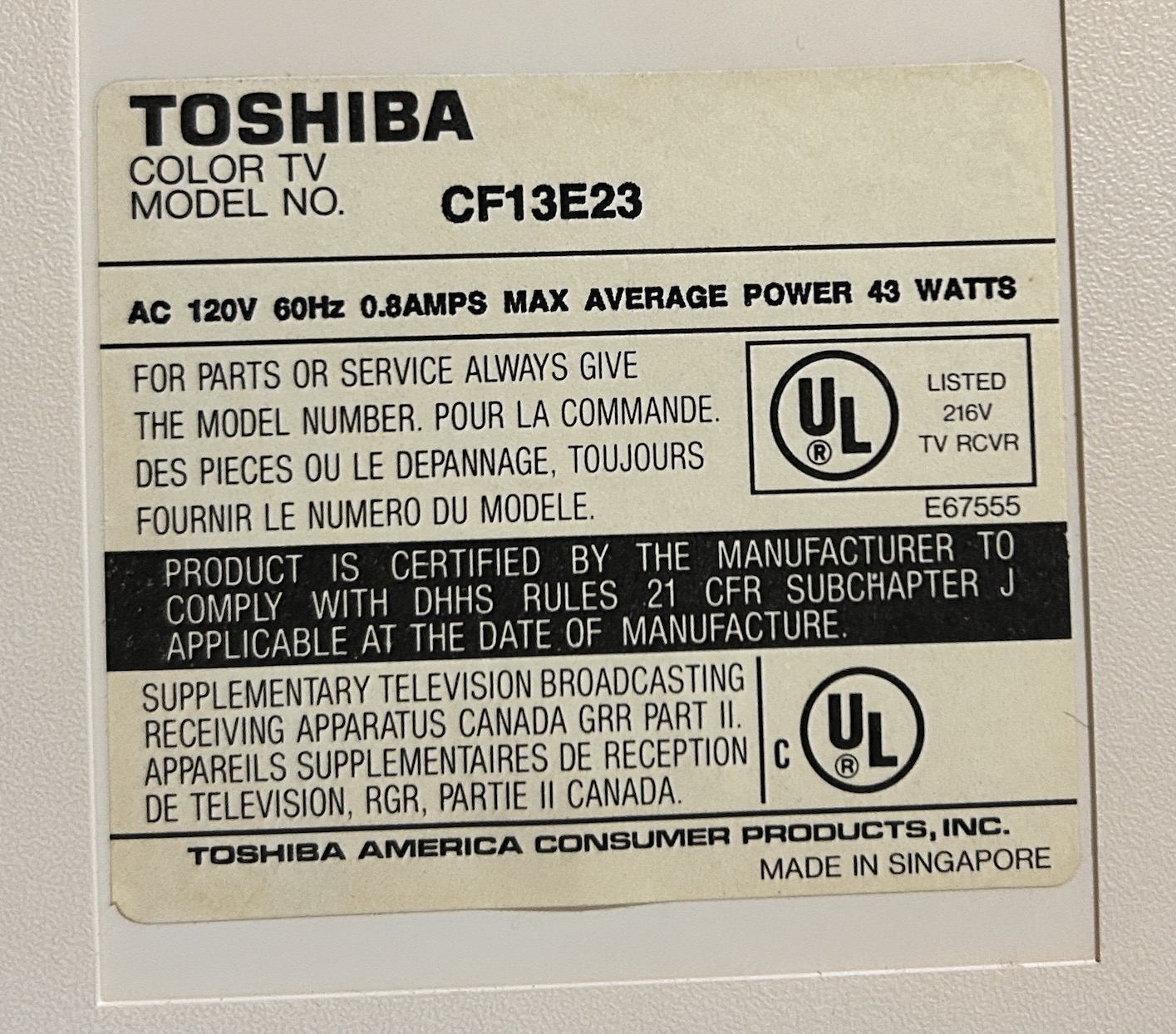
Neckboard 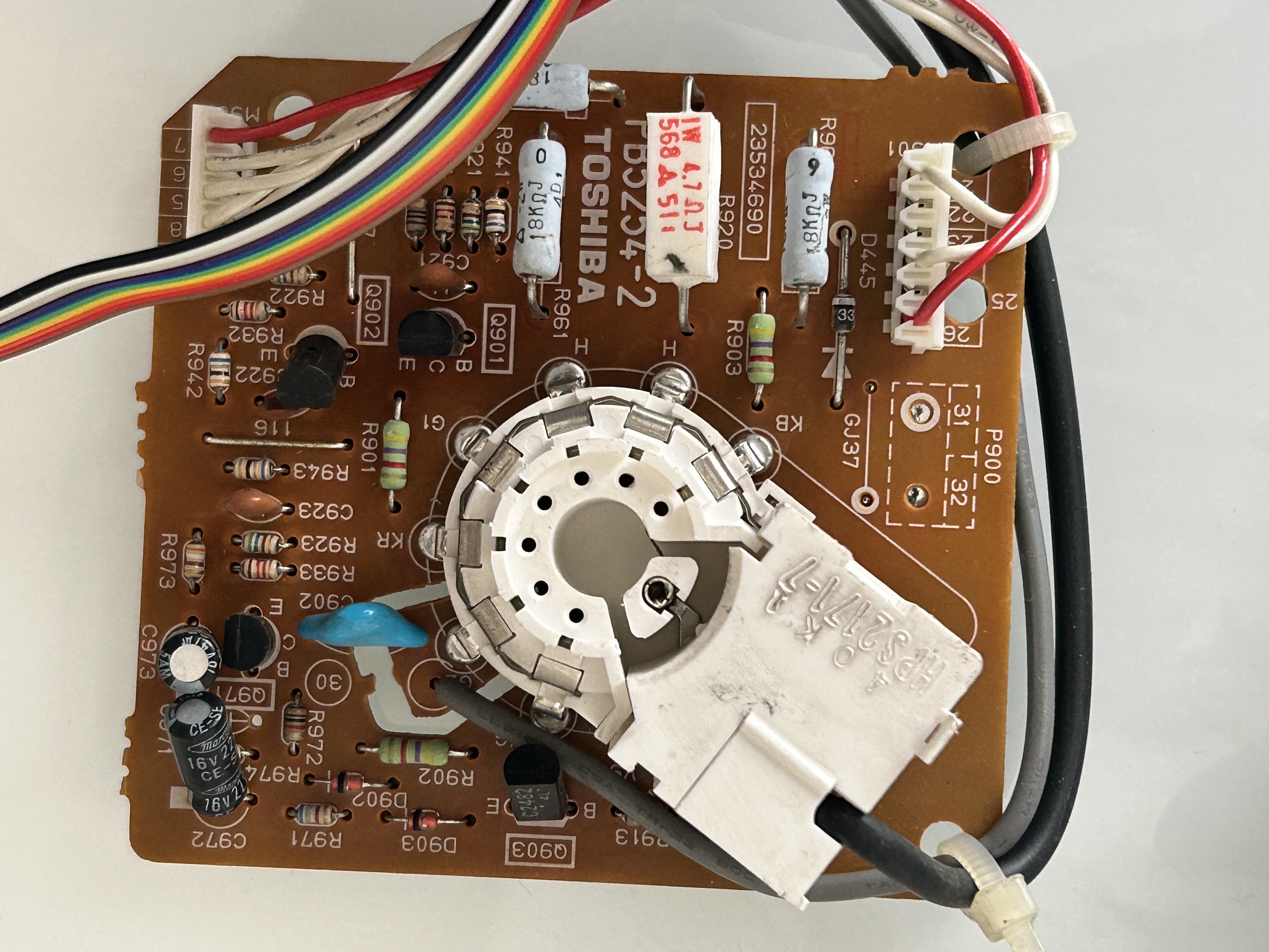
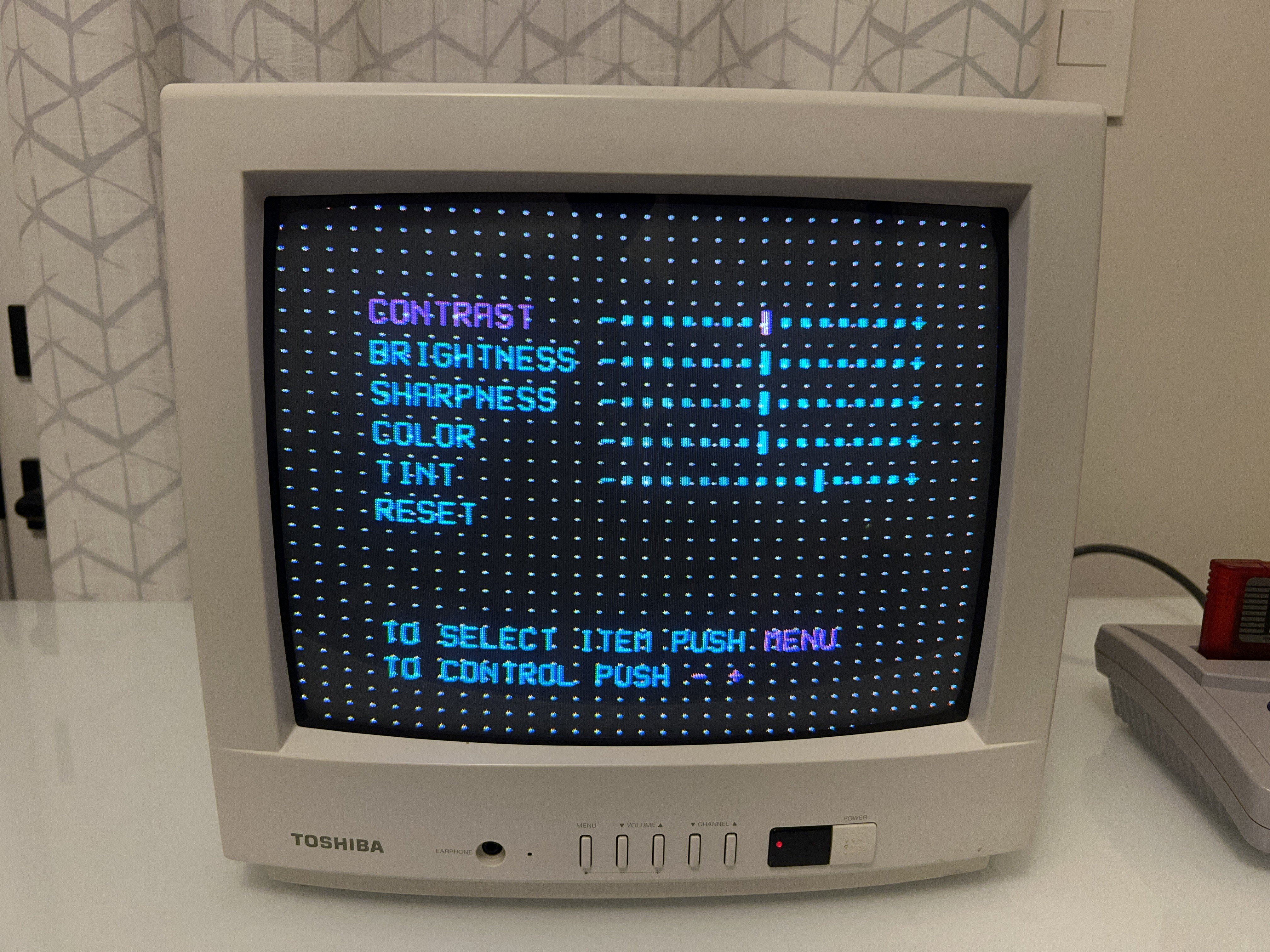
Service Menu
Press Mute on the remote. Press Mute again on the remote and keep pressing. Press Menu on the CRT to enter Service Mode
Press Menu again on the CRT for options. CH buttons to change option. VOL buttons to increase/decrease values
Design mode
Press Recall on the remote and press Menu on the CRT to enter Design Mode
Pictures
Reference Photos