Toshiba 20AF43+
Toshiba 20AF43+ CRT RGB mod
The Toshiba 20AF43 is a 20" flat-screen CRT television released in 2003. This model features video inputs including Composite, Component, and S-Video, delivering a sharp, vibrant picture that is ideal for classic 240p consoles. Unlike the larger 27" AF series, the 20" and smaller screens do not experience the horizontal distortion often noticed in side-scrolling games.
Toshiba 20AF4x CRTs are RGB moddable.
View full CRT details and more mod examples →
This tutorial covers the RGB mod for the below models.
- Toshiba 20AF43
- Toshiba 20AF44
- Toshiba 20AF45
- Toshiba 20AF46
Please also see other Toshiba AF series mods, as the instructions are more or less the same.
Table of Contents
Contributors
Thank you to everyone who contributed to this guide:
- Sunthar — contributor, RGB mod and pictures
CRT safety
Caution
You can die doing this! So read carefully! CRT TV is not a toy. Do not open a CRT TV. If you don't have any prior knowledge about handling high voltage devices, this guide is not for you. CRT TV contains high enough voltage (20,000+ V) and current to be deadly, even when it is turned off.
Plan of attack
Manuals and Datasheets
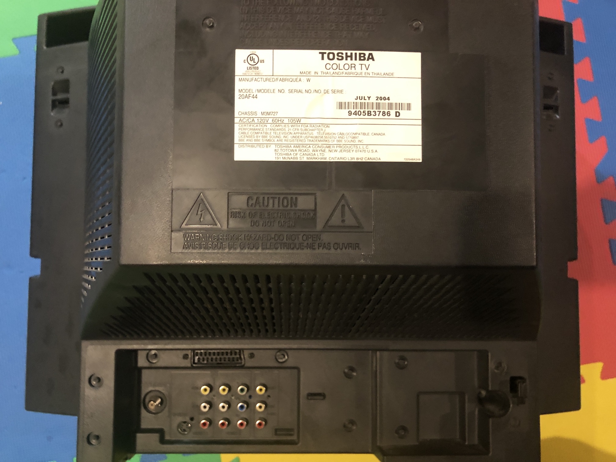
Specs
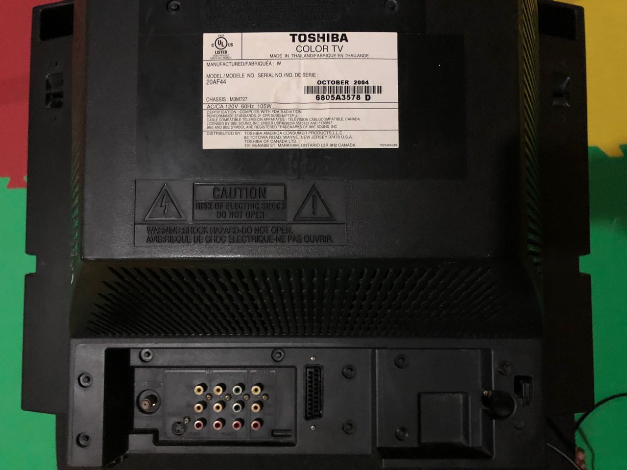
- Year: 2004
- Format: NTSC
- Chassis: M3M727
- Tube: Orion A51LVV896X07
- Jungle Chip: M61283FP
- OSD Chip: OEC7090A
- Screen Size: 20"
- Weight: 50.6 lbs
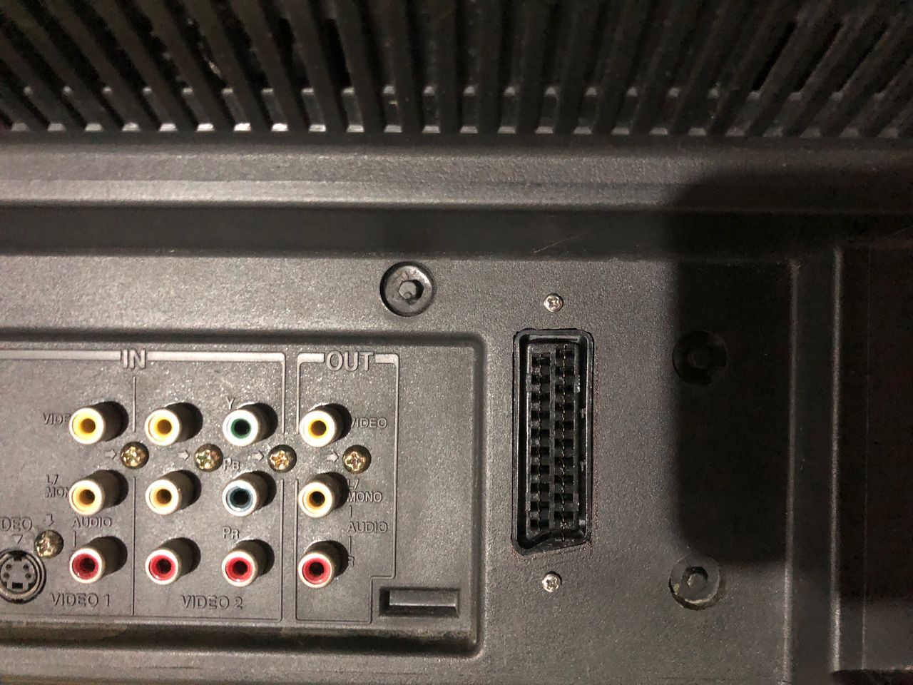
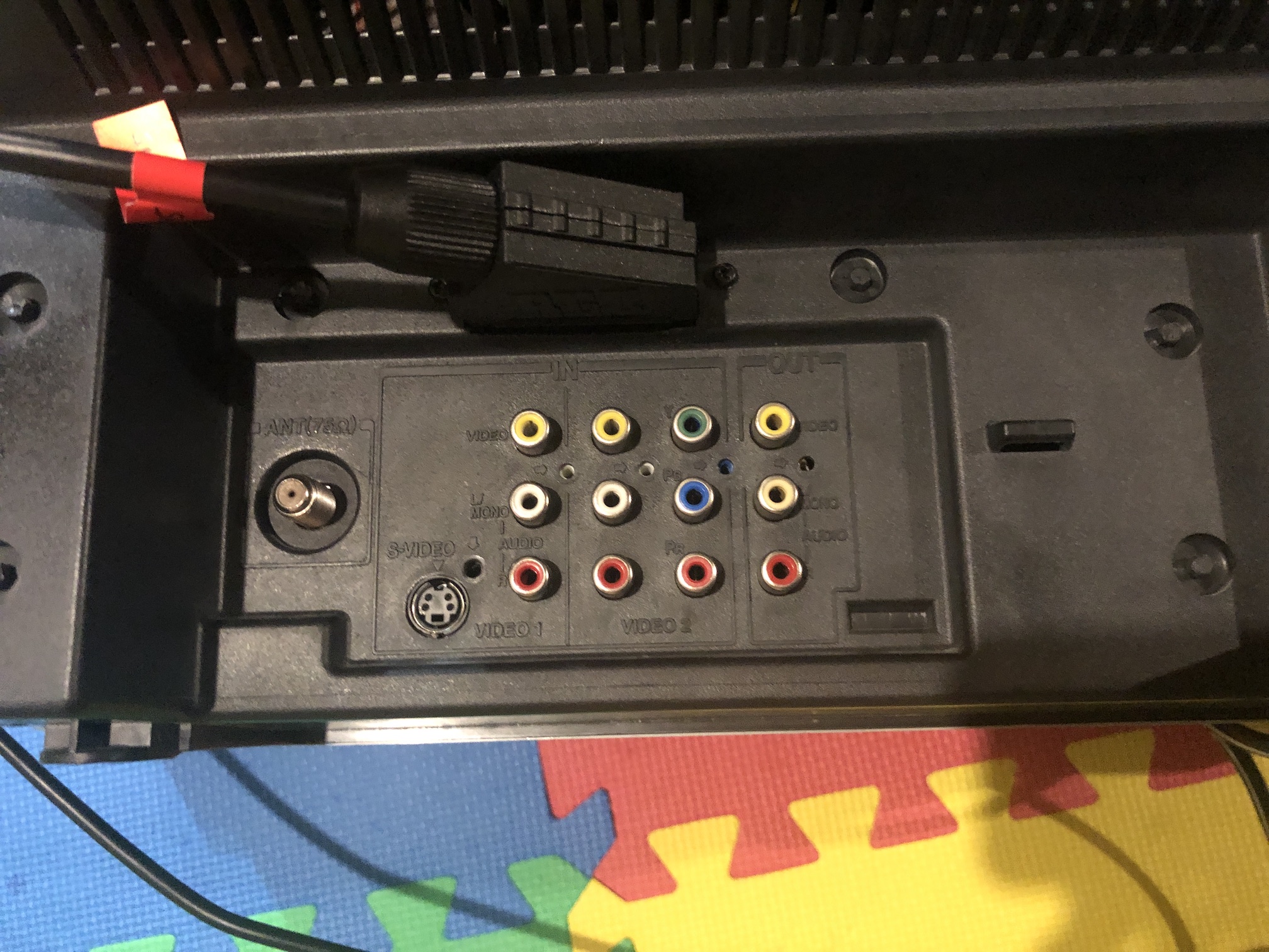
- Inputs: Composite, S-Video, RF, Component YPbPr
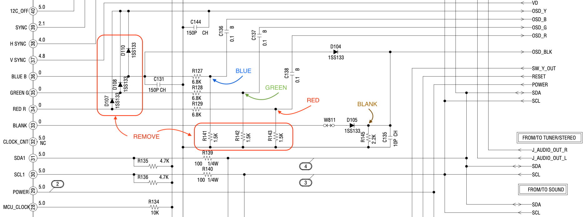
Schematics
Get hold of the schematics for your TV. Understand where the RGB and Fast Blanking signals go from OSD to the Jungle (Chroma) chip.
If you are building your own circuit, this diagram should help. Check the alternate method for ringing noise reducing circuitry.
20AF43/20AF44
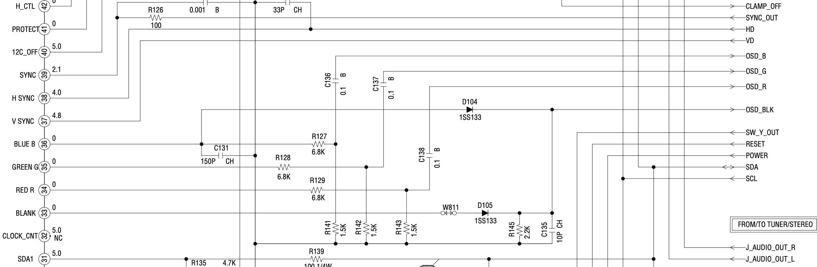
20AF45/20AF46
The biggest difference between 20AF44 vs 20AF45 is there is no VM circuitry (the one that is used for edge enhancements). Therefore, D107, D108 and D110 are missing from this schematics.
RGB mux diagram
Prepare the mux diagram. If you are building your own circuit, this diagram should help.
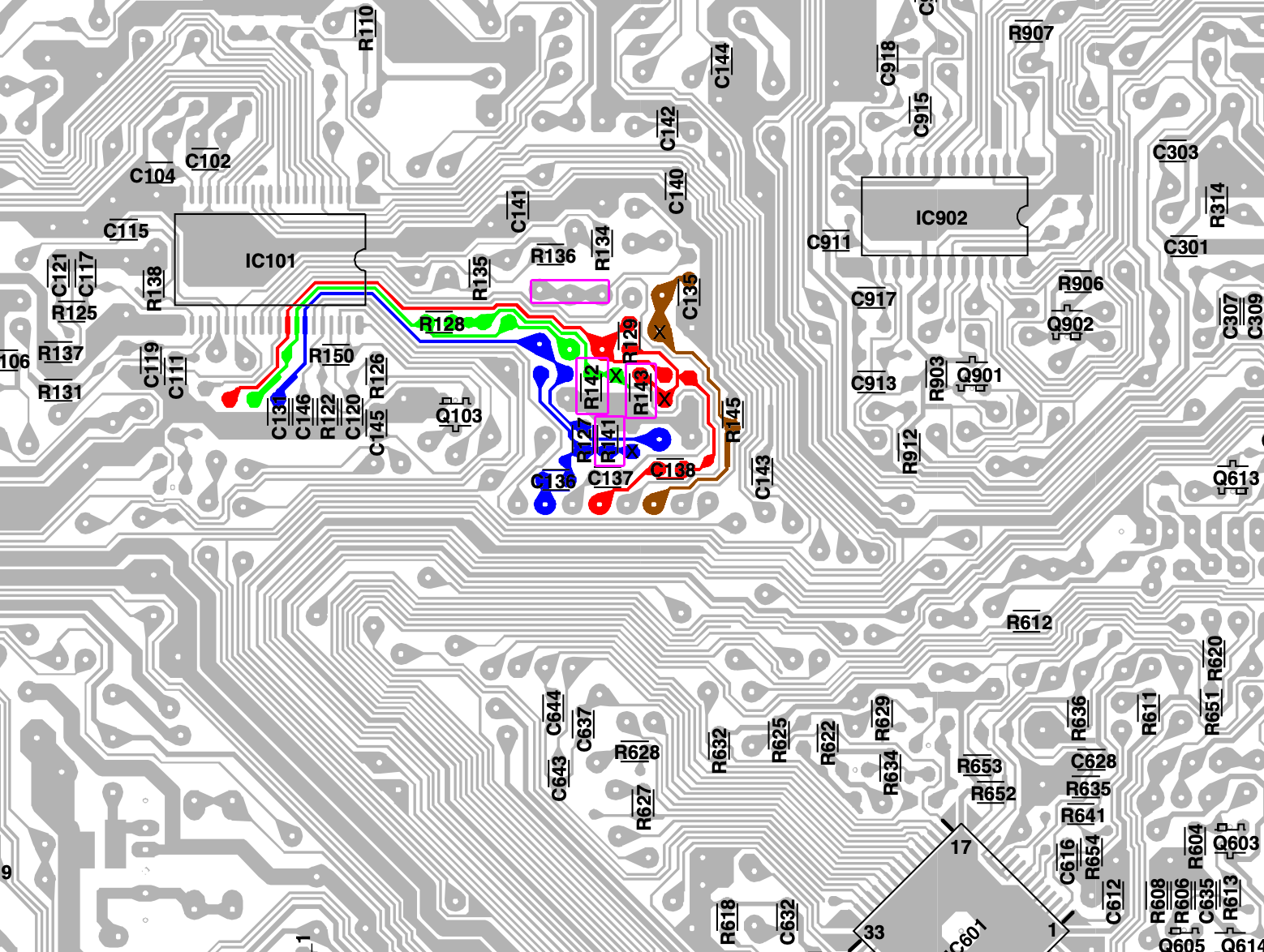
PCB
20AF43/20AF44/20AF45/20AF46
Points where the R, G, B and Blank wires should be connected are marked "X". Pink boxes show the resistors, diodes that needs to be removed.
Actual PCB might be slightly different for 20AF45 and 20AF46. However, the mod that needs to be applied is in similar location.
Performing the mod
STEP 1: Remove the following components
20AF43/20AF44
Remove the RGB resistors to ground
- R141
- R142
- R143
There were no coupling capacitors to ground that needed to be removed
Tips
Did not remove C131 or C135. Removing them can affect the background of the OSD.
VM can be disabled in two ways
Method 1: Unplug the VM cable on the neck board. 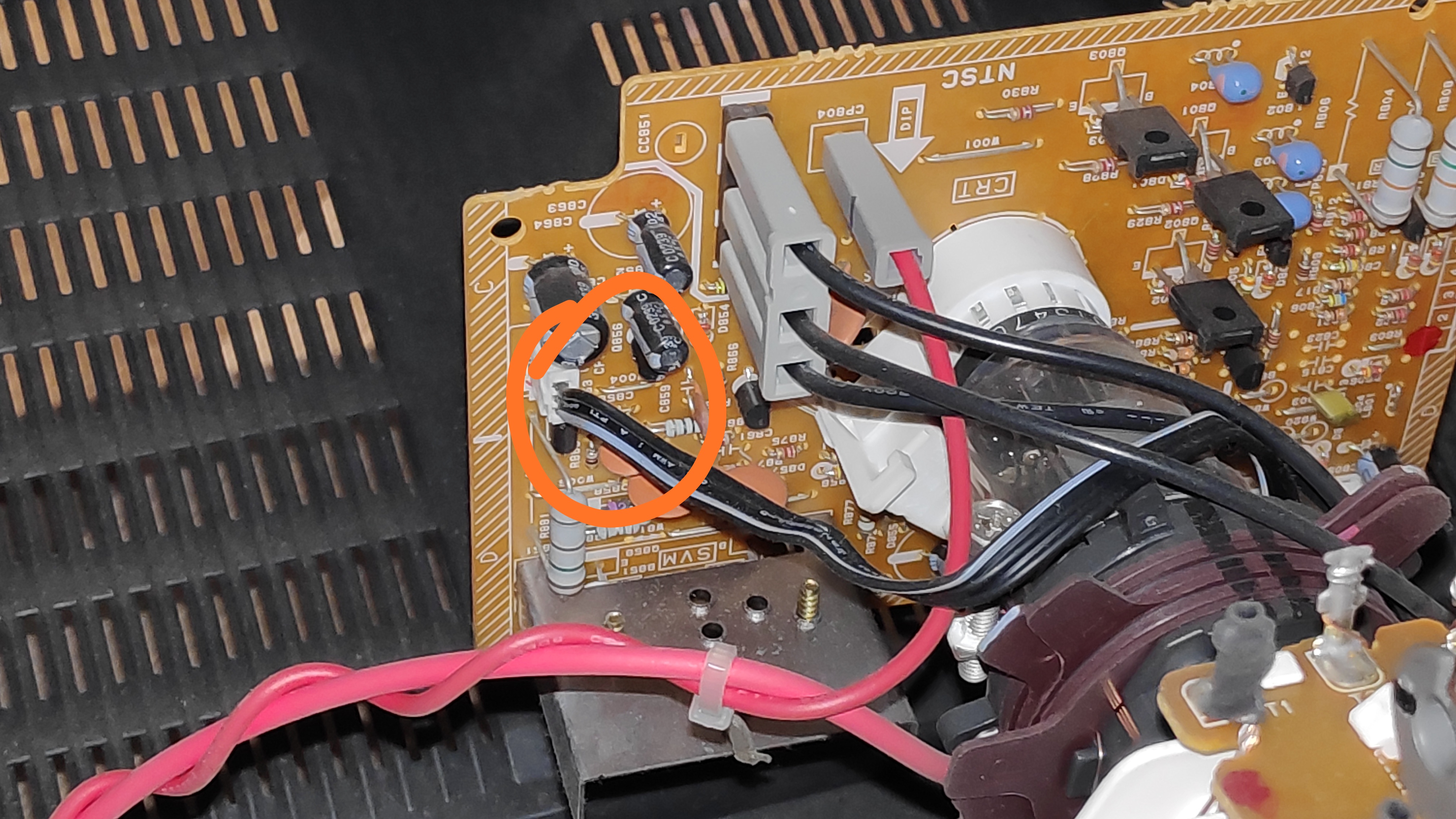
Method 2: Remove diodes that enable VM from the RGB lines (not recommended)
- D107
- D108
- D110
20AF45/20AF46
Remove the RGB resistors to ground
- R141
- R142
- R143
There are no VM cables to unplug on the neck board. No VM diodes to remove on this board.
STEP 2: Connect RGBs, Blanking and Audio
20AF43/20AF44/20AF45/20AF46
Connect the RED, GREEN, BLUE, BLANKING wires 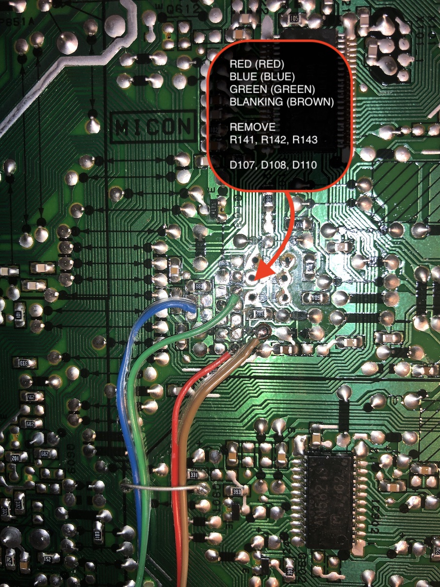
Connect the SIGNAL, AUDIO RIGHT, AUDIO LEFT, GROUND wires 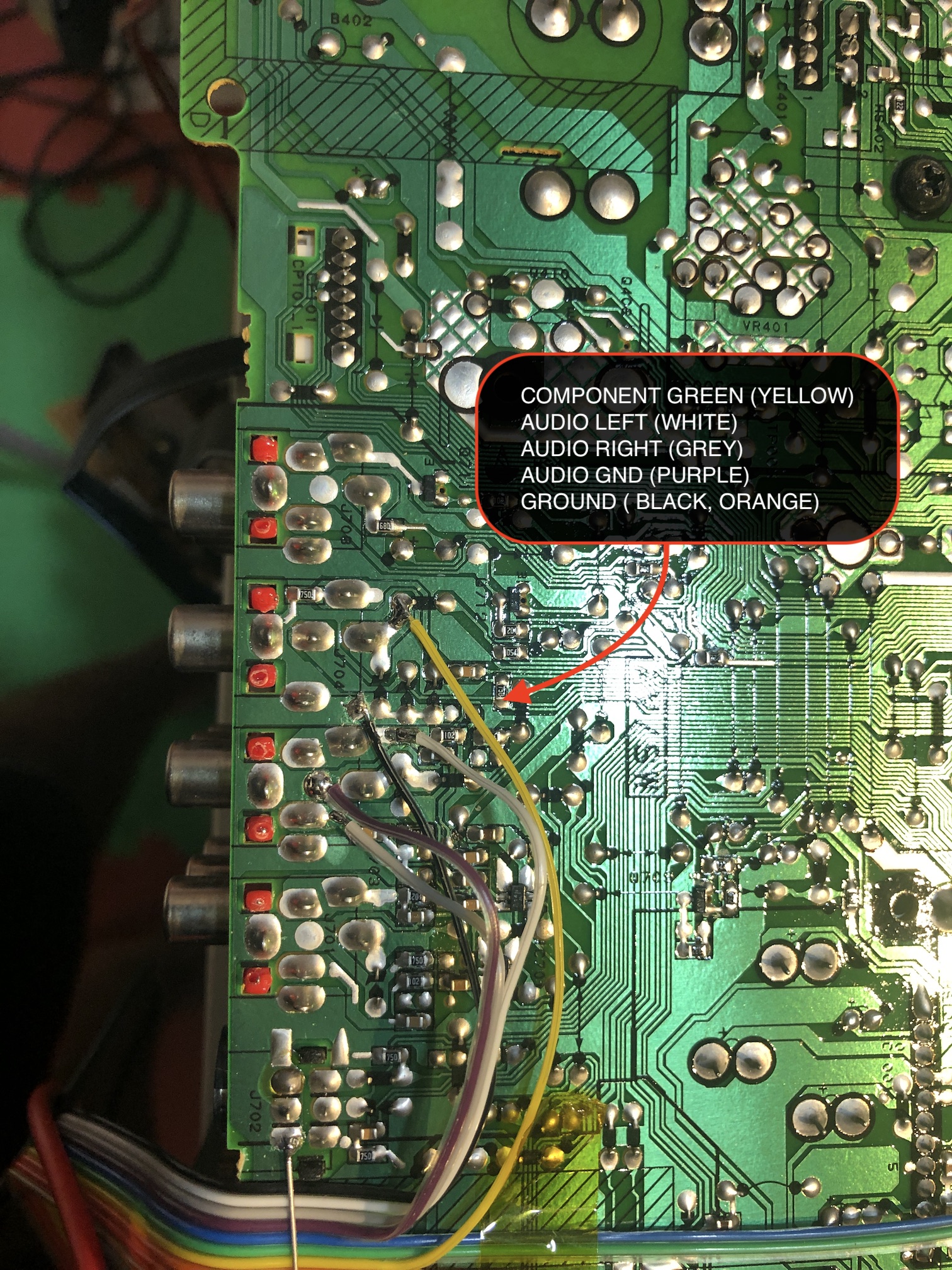
STEP 3: Build your mux circuit
This mod uses the RGB mux board. This is optional, but will make your mod easier and stable. You can also create the circuit presented in the schematics above without the board. Please also checkout the mux calculator to play with your own values.
| On Toshiba CRT Chassis | 20AF43 |
|---|---|
| CRT RGB inline resistor | 6.8kΩ |
| CRT RGB ground resistors removed | 1.5kΩ |
| 0.1μF caps replaced | Yes |
| Add diodes on chassis RGB lines? | Yes |
| Add blanking diode on chassis | No |
| RGB mux board | 20AF43 |
|---|---|
| Mux board RGB termination (R1, R2, R3) | 75Ω |
| Mux board RGB inline resistors (R4, R5, R6) | 1.2kΩ |
| Mux board Audio LR (R7, R8) | 1kΩ |
| Mux board blanking diode (R9) | 1N4148 |
| Mux board blanking ground resistor (R10) | open |
| Mux board blanking resistor (R11) | short |
Based on the chassis RGB inline resistor value, you may want to choose different RGB inline resistors on your mux board. However, I have noticed in general 1kΩ resistors just works well.
| TV Model | 20AF42 | 20AF4x | 20AF4x | 20AF4x |
|---|---|---|---|---|
| RGB/OSD stock resistors | 4.7kΩ | 3.3kΩ | 3.9kΩ | 6.8kΩ |
| RGB inline resistors (R4, R5, R6) | 680Ω | 470Ω | 560Ω | 1kΩ |
Toshiba 20AF45 RGB mux adapter 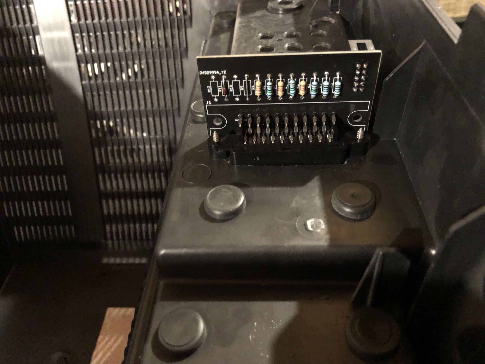
Toshiba 20AF44 RGB mux adapter 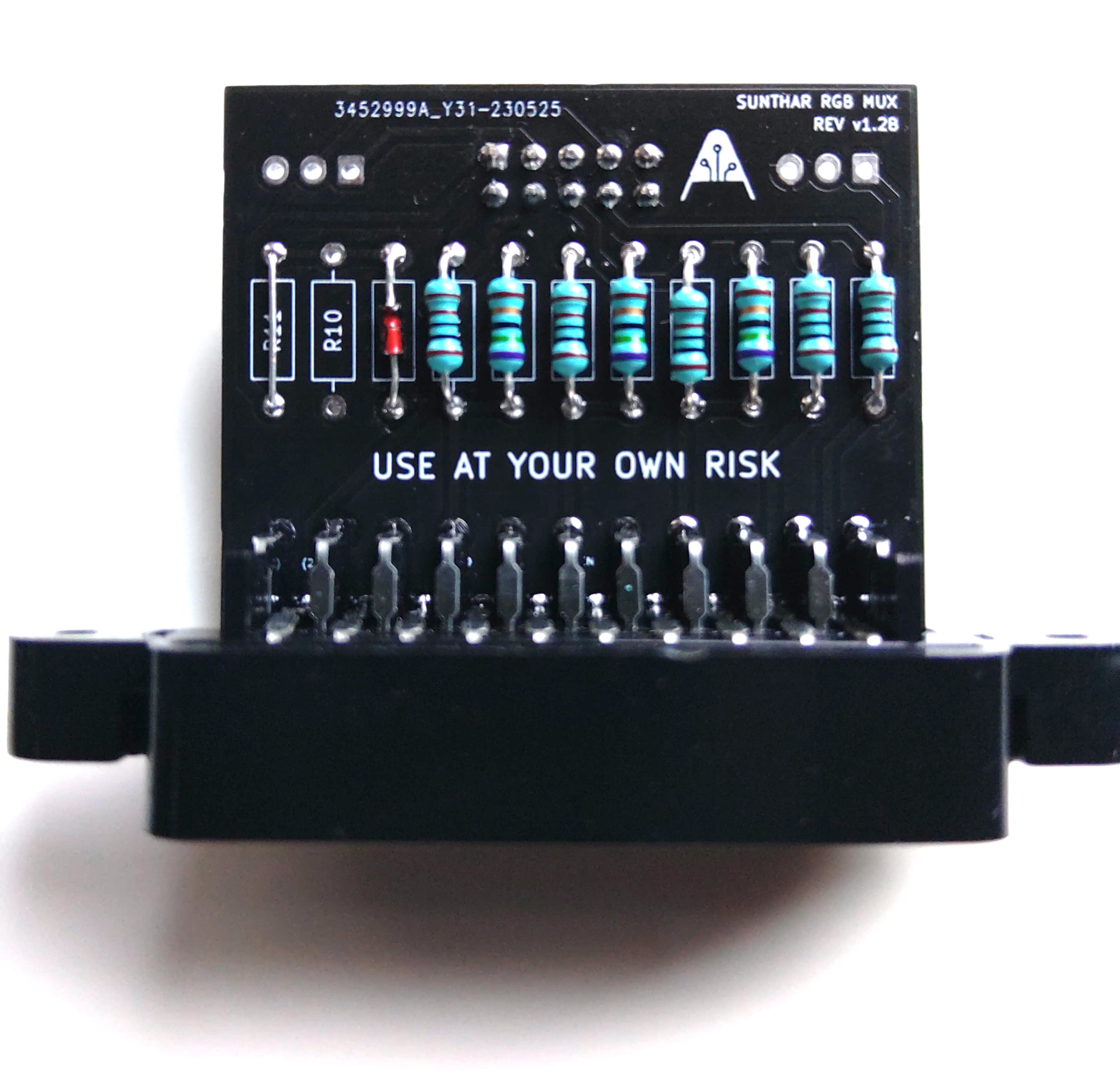
STEP 4: Attach the female SCART connector to TV
Creating a SCART cutout and mounting it is an art. I have a dedicated section for it.
How to create and mount a SCART female plug?
Alternate method to reduce ringing noise
If you don't have diodes on the OSD RGB lines connecting to the chroma chip, the RGB signals that comes from the console can hit the OSD chip and reflect back, causing a minor interference. While not very noticeable, if you are keen on keeping all forms of noise away from your mod, you should follow the below directions.
STEP 1: Remove the ground resistors.
- R141
- R142
- R143
Also remove the 0.1uF SMD caps that are inline and short them
- C136
- C137
- C138
Remove jumpers
- W107
- W108
- W112
STEP 2: Introduce diodes and 0.1uF caps
Mux Diagram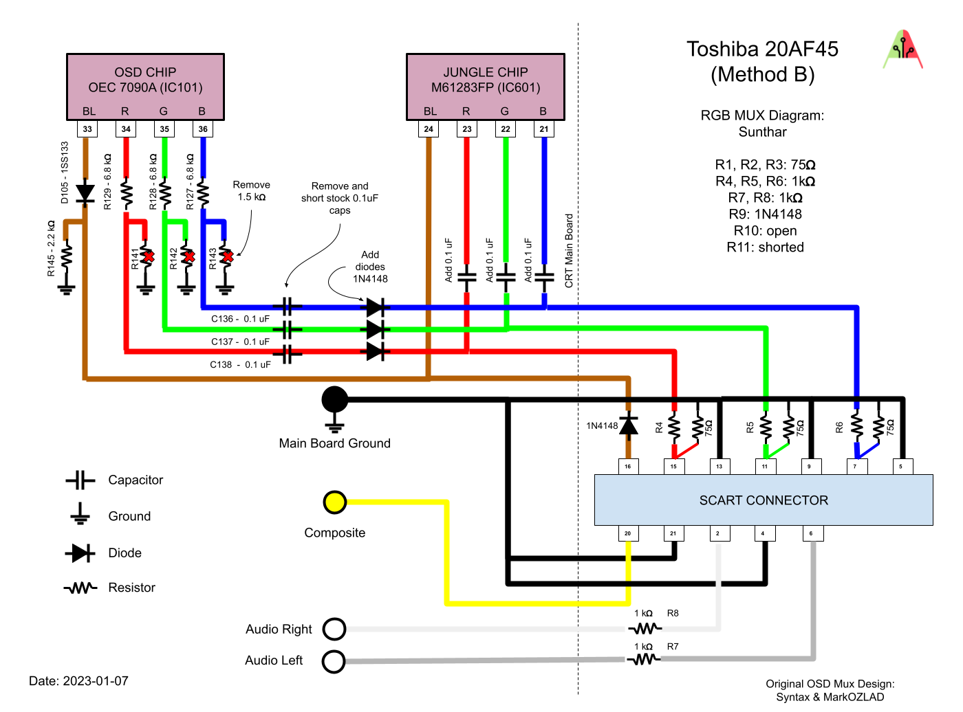
Connect RGB, Blanking wires
Remove the jumper wires W107, W108 and W112 that feeds the R, G, B lines from OSD to Chroma. This is an important step to perform. 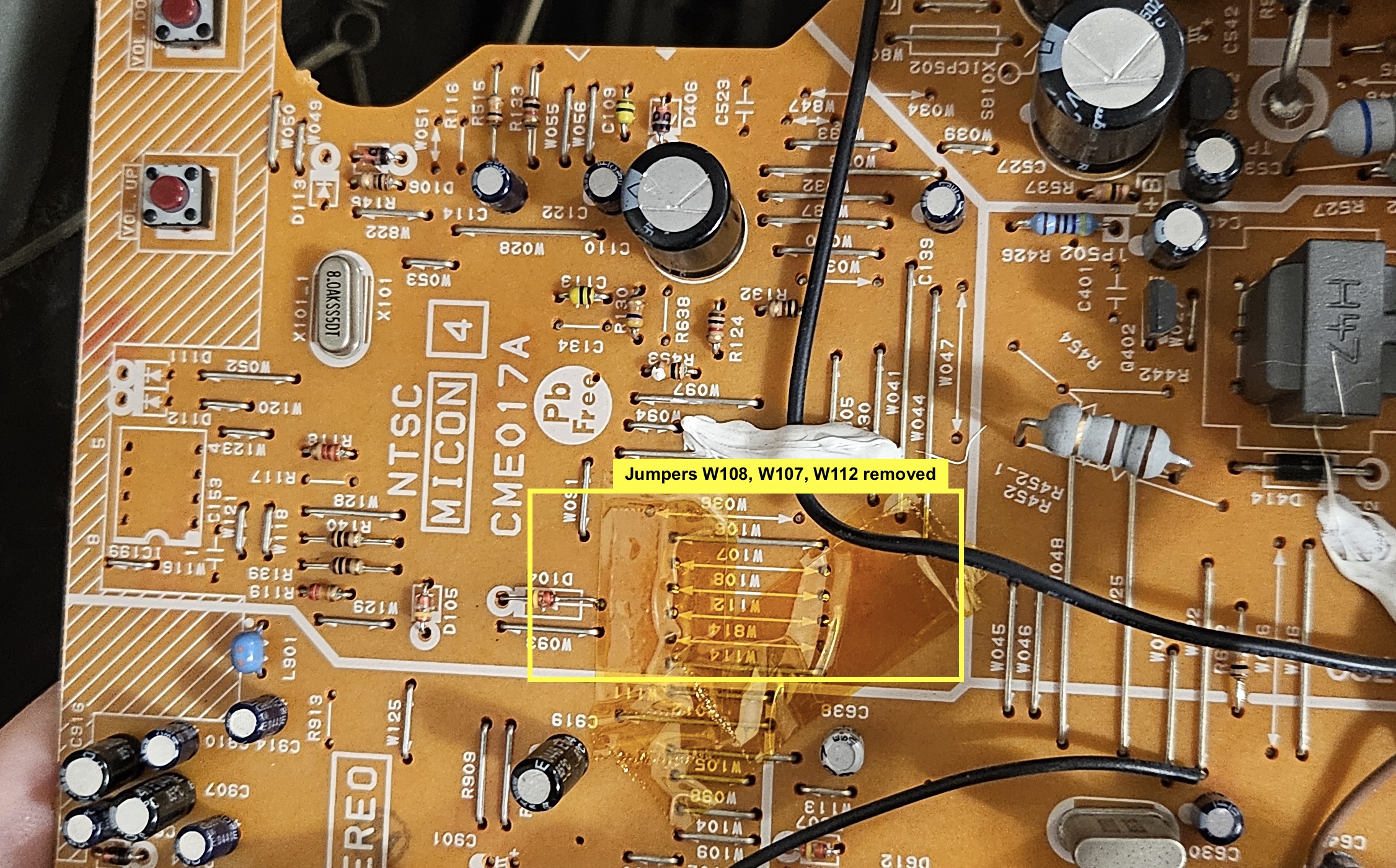
Removed caps are bridged. Caps and didoes added. Pay attention to the direction. 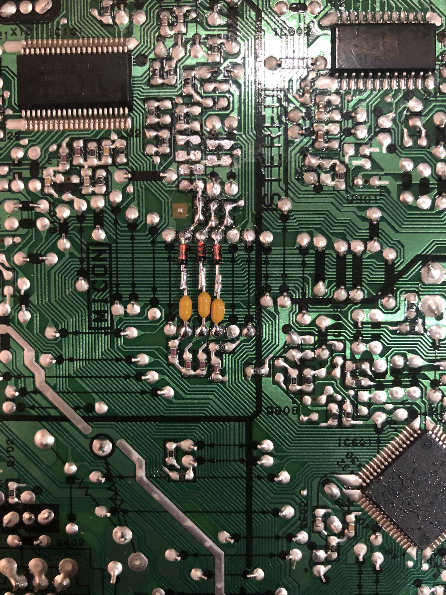
Blanking wires and RGB wires attached. ![]()
Connect Audio, Sync and Ground wires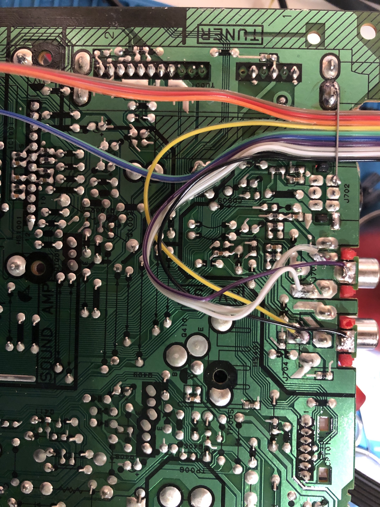
STEP 3 and 4
These are the same as above. Only difference here is the RGB inline resistance value to use will be 1.2kΩ instead of 1kΩ. This is to compensate for the addition of the diodes. In general, I've noticed using 1kΩ for R4, R5, R6 works just as well without any degradation in picture quality.
Pictures (20AF44)
Finished mod
Yes, screws are missing. They were put in later!
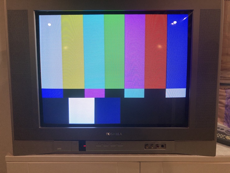
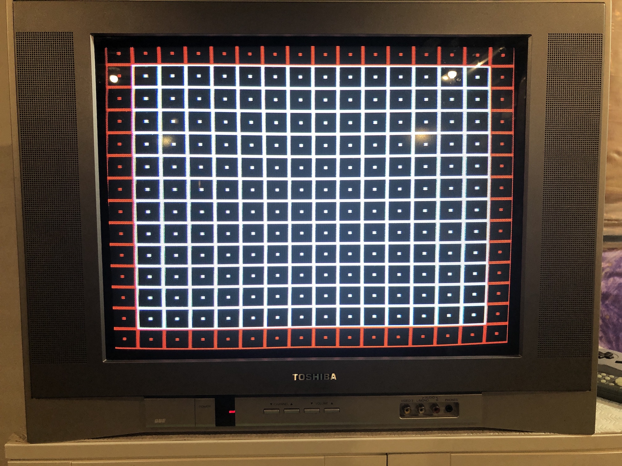
Test patterns
Not the best image quality. But, looks pretty decent for a flat CRT TV.
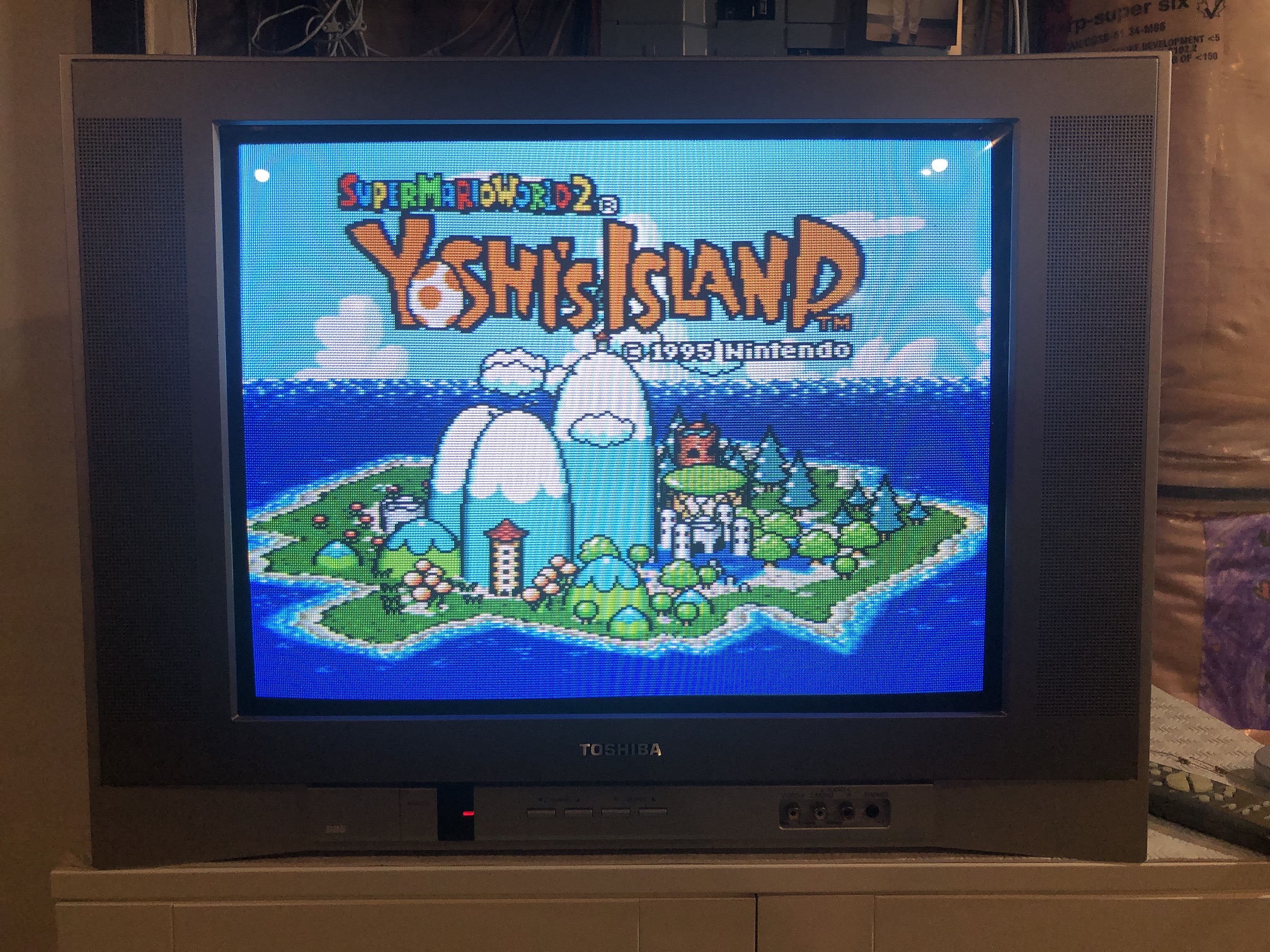
Games
Pictures (20AF45)
Mux board and port
SCART port 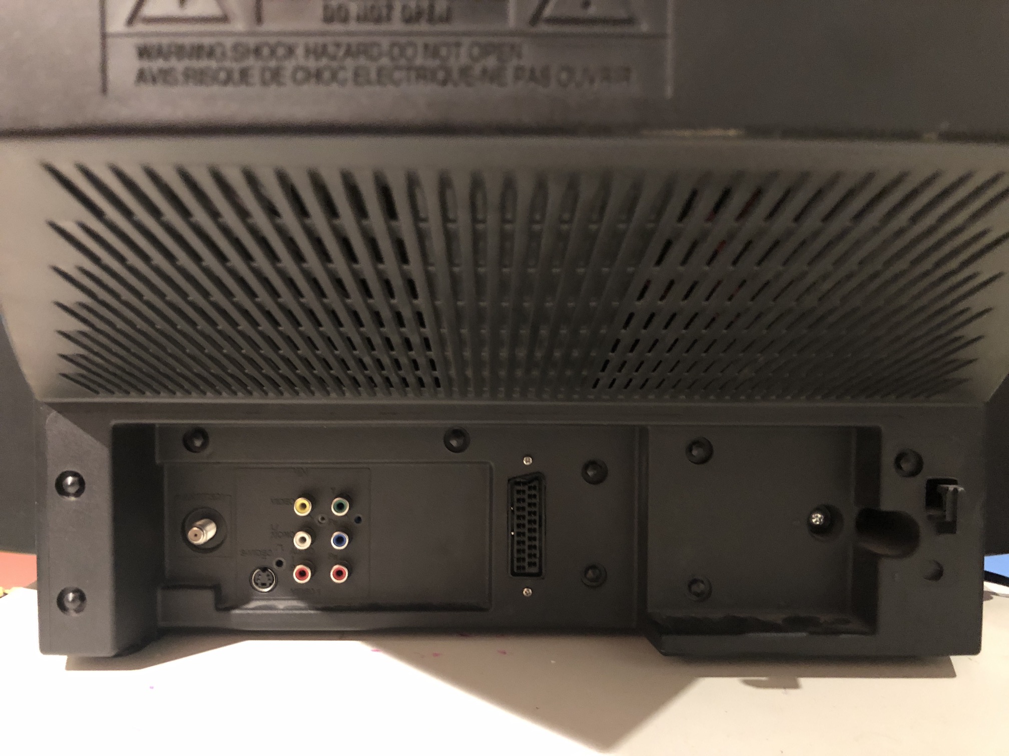
Cable connected 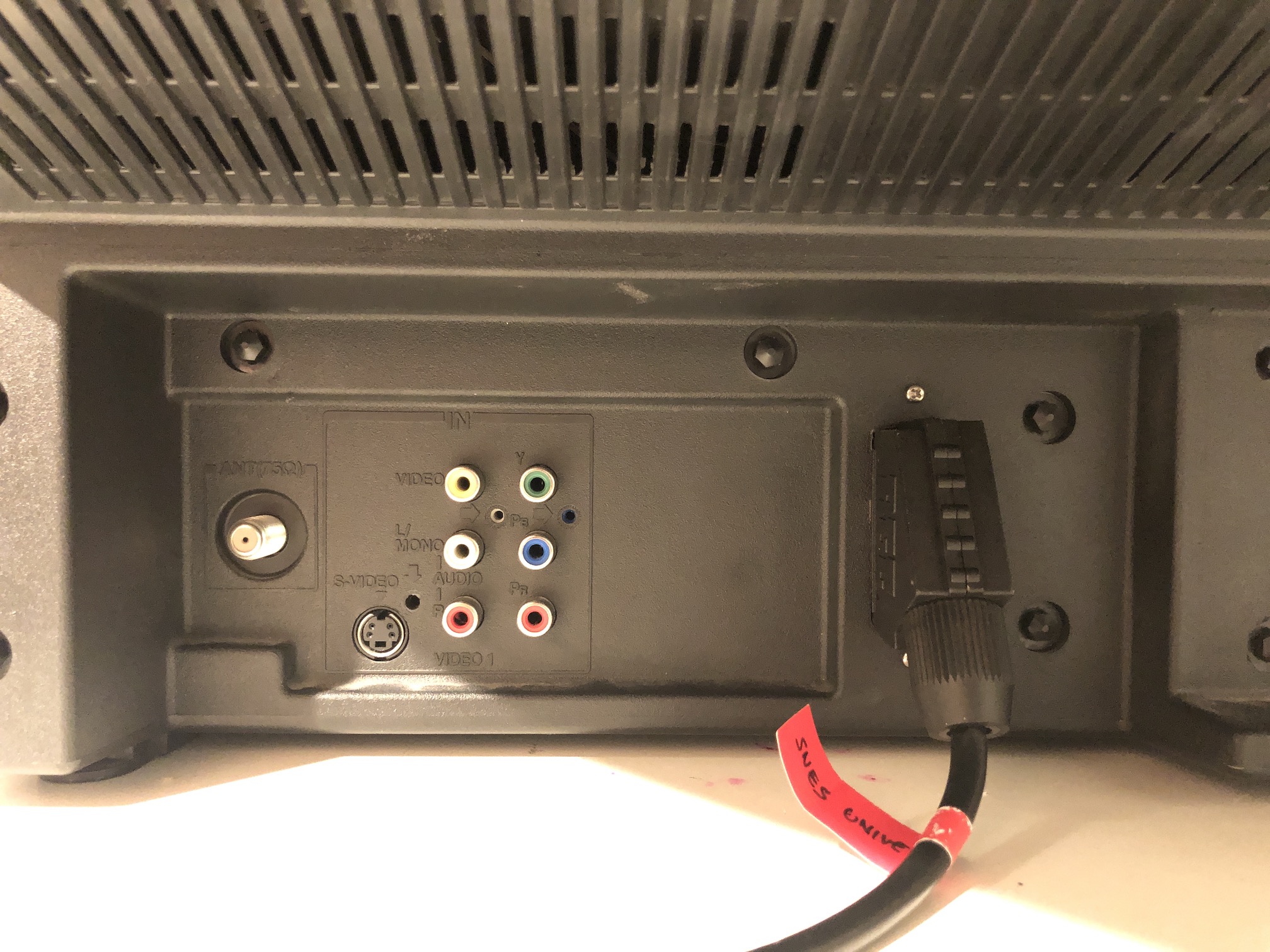
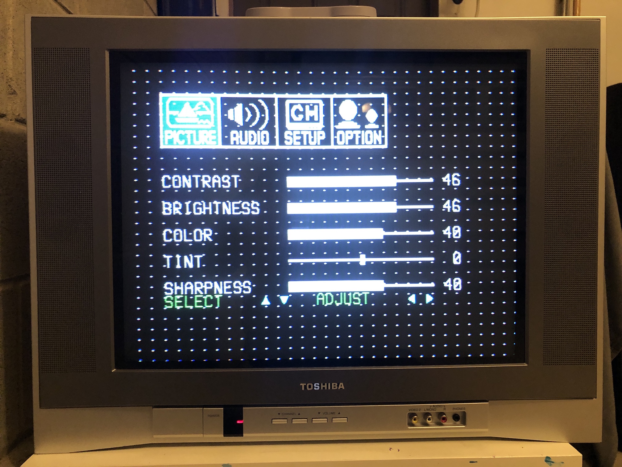
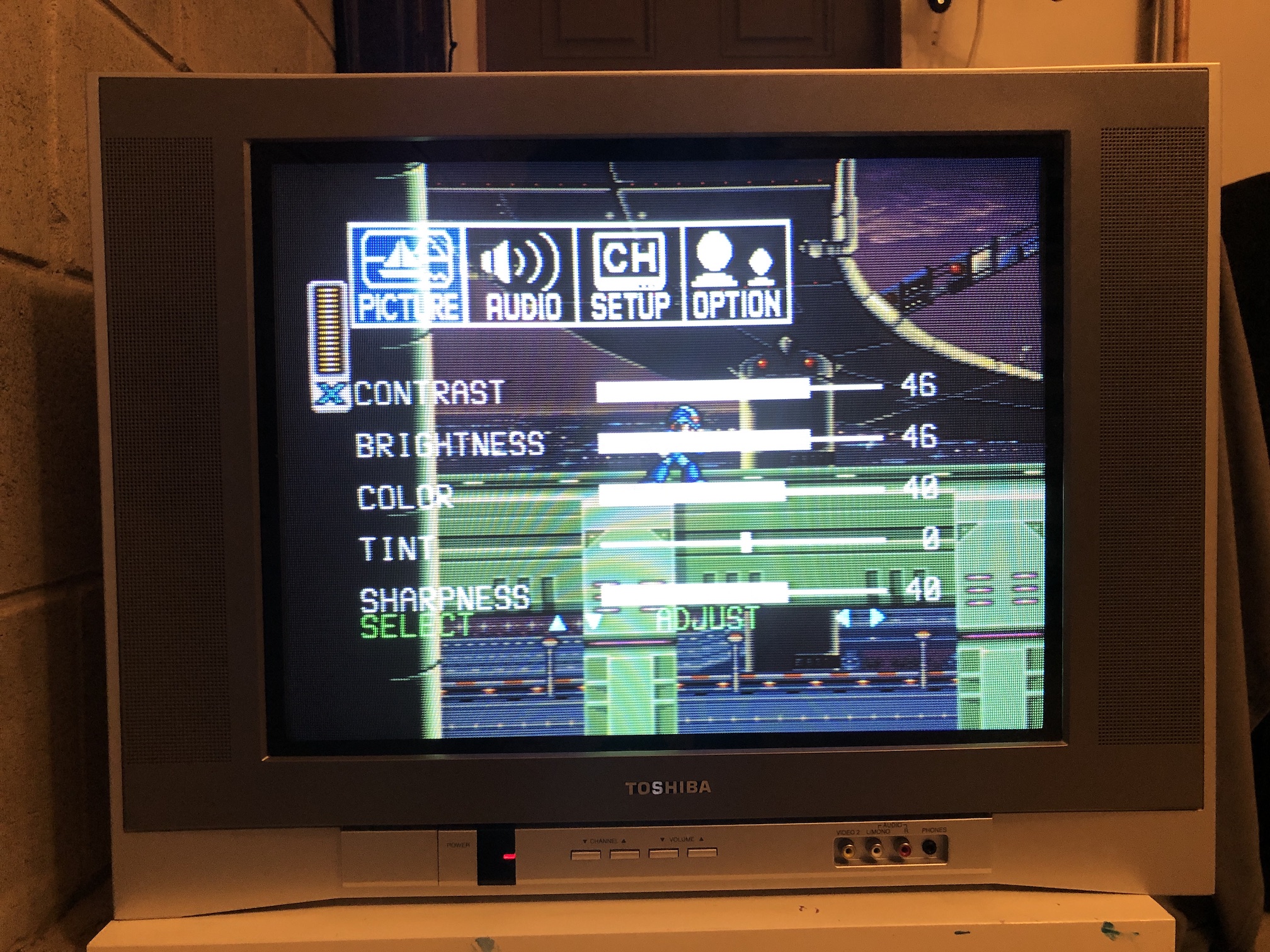
OSD Mux overlay
Games
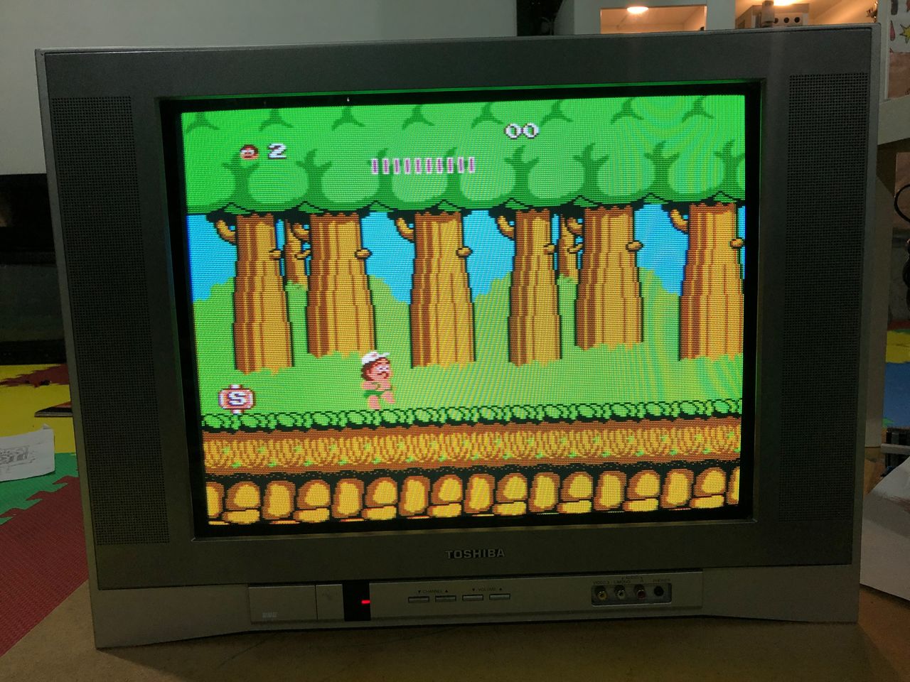
SNES - Super Mario World 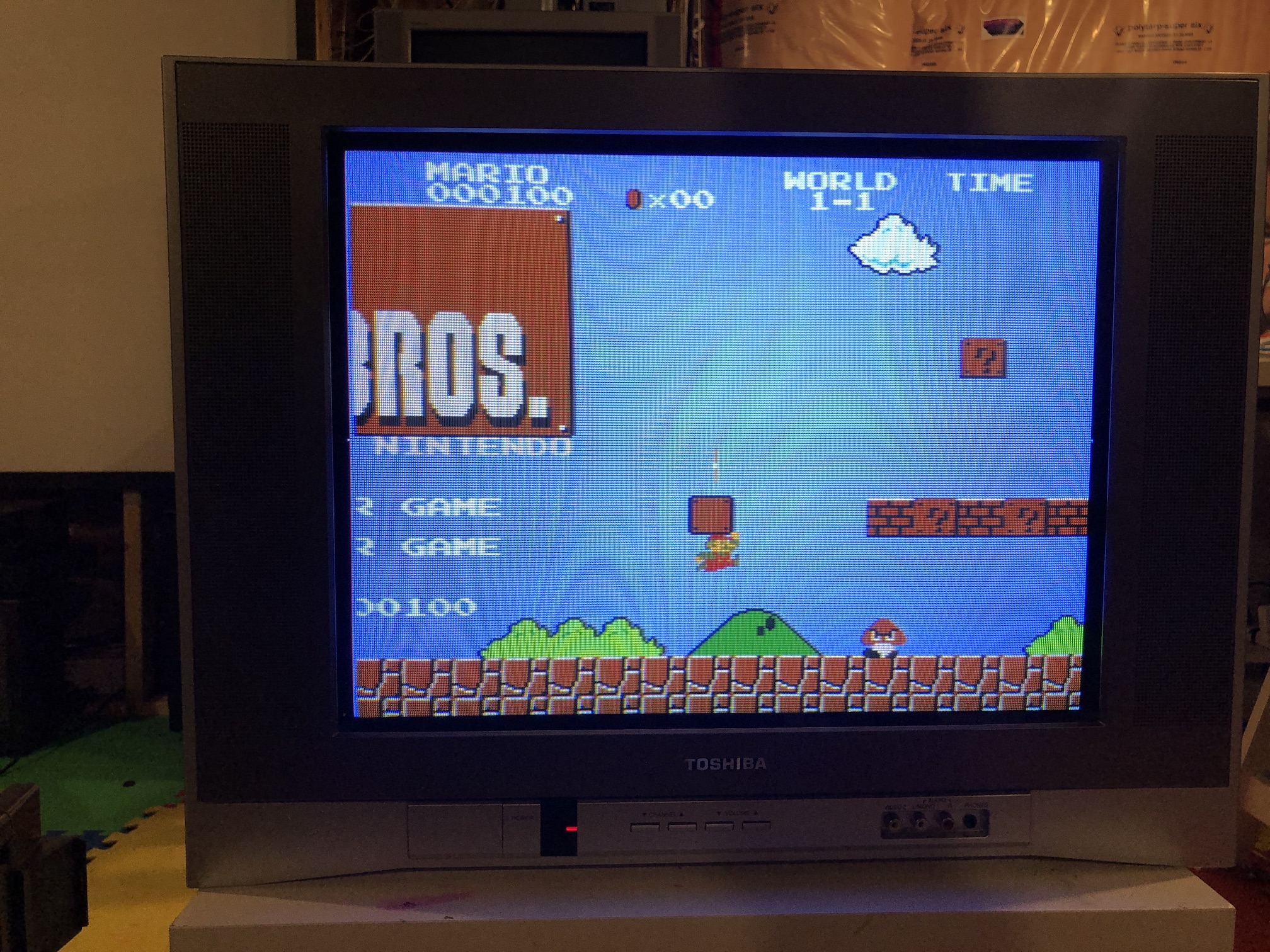
SNES - Metroid 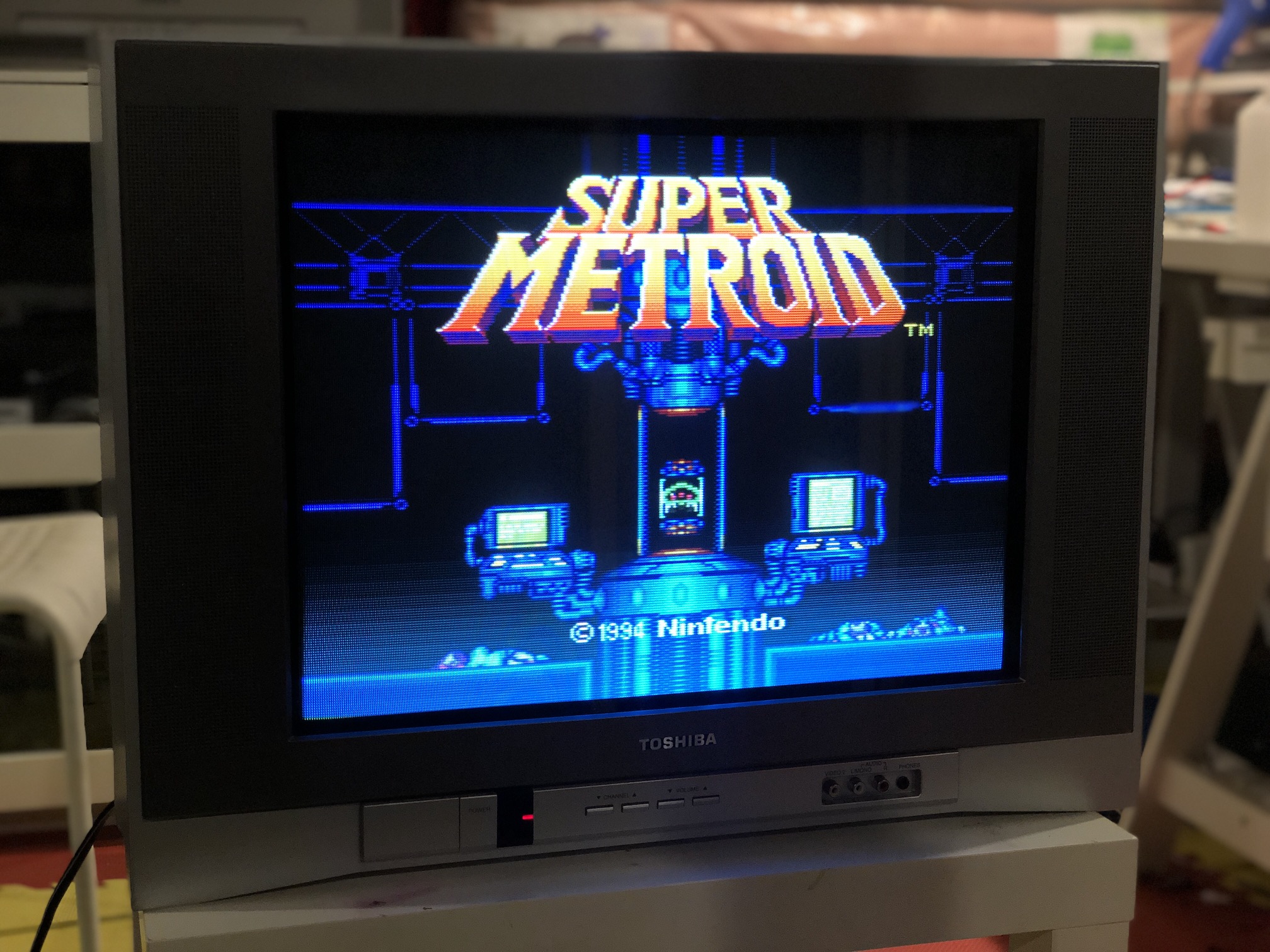
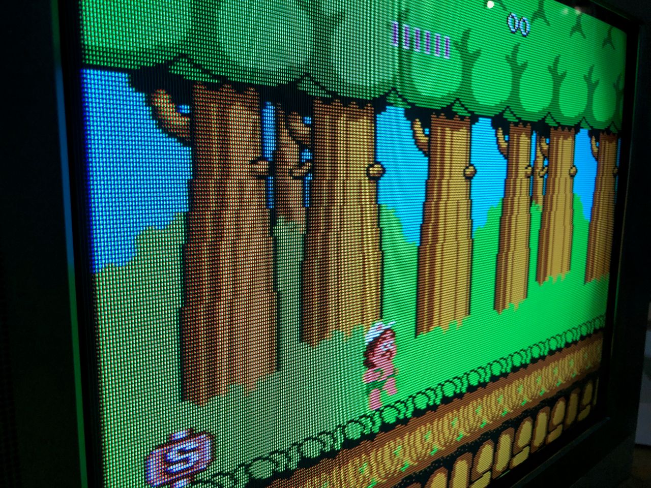
NES - Adventure Island 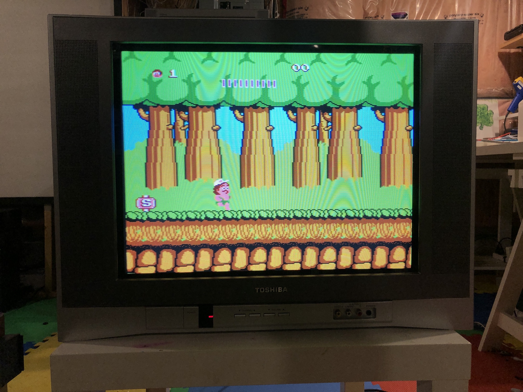
XBOX - UnleashX 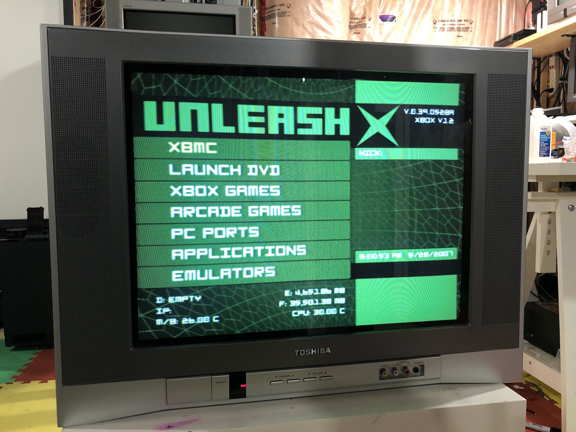
Sega Genesis - Sonic 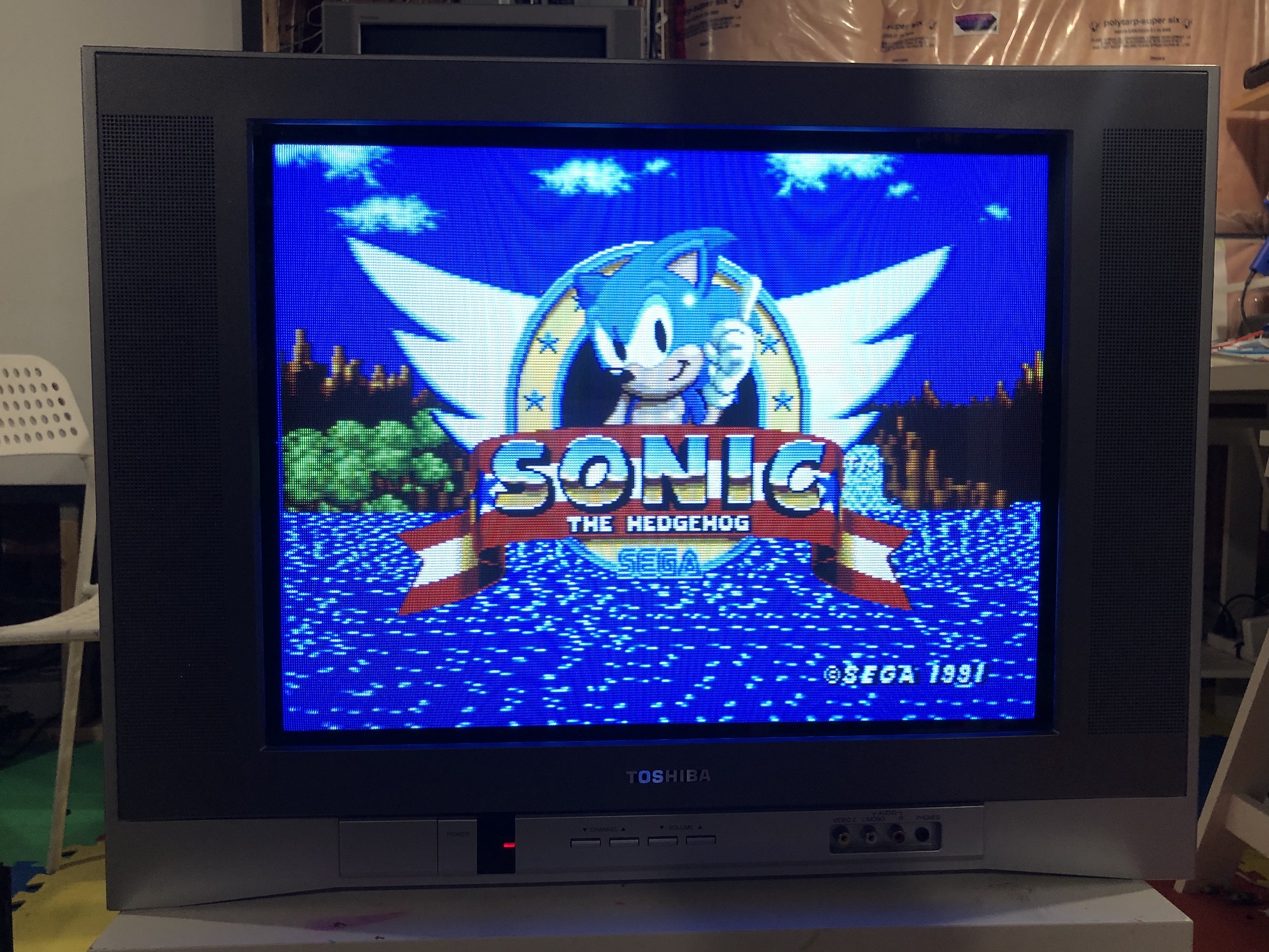
Patterns
Convergence 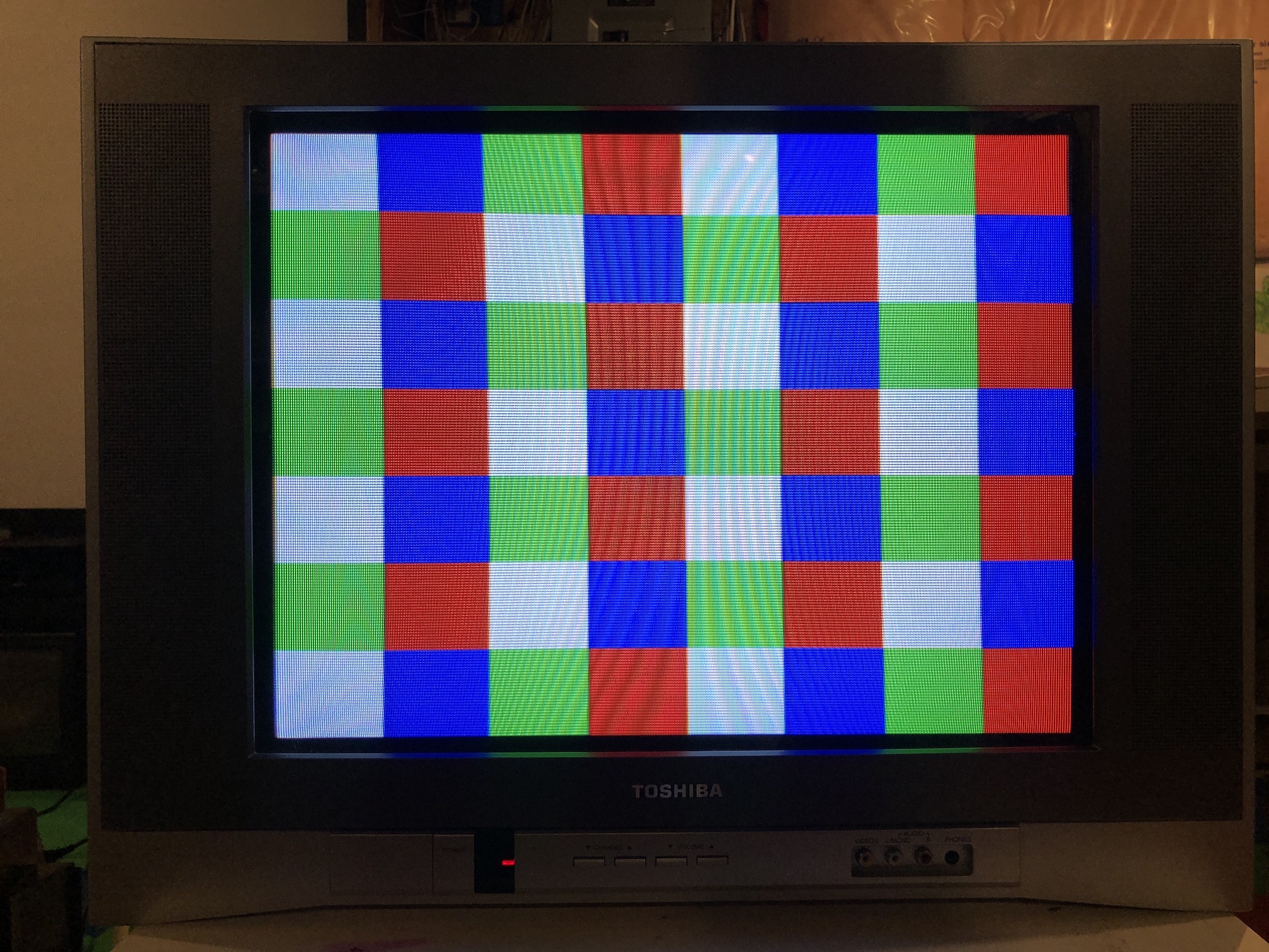
Monoscope 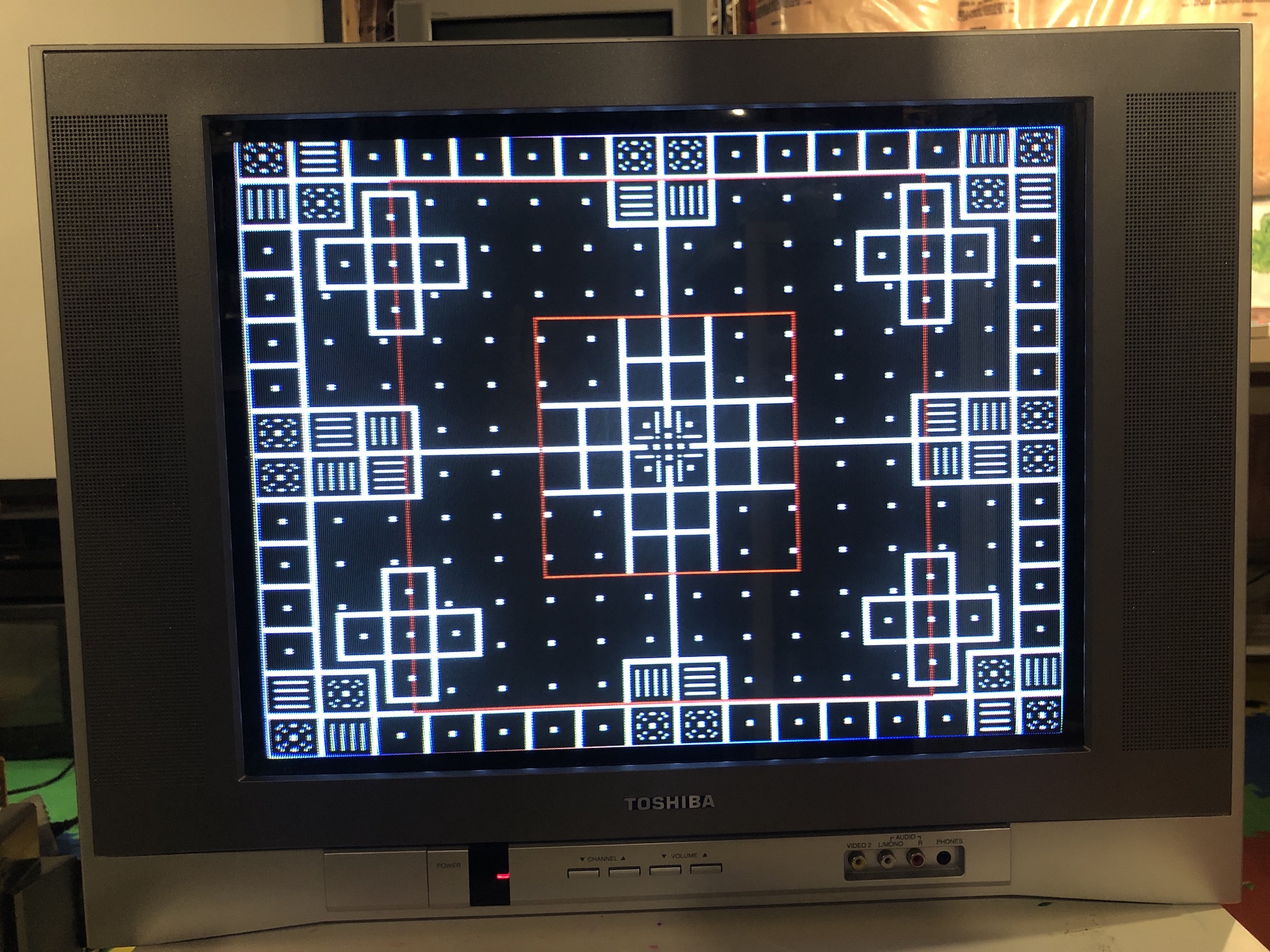
Tube and Board
Tube 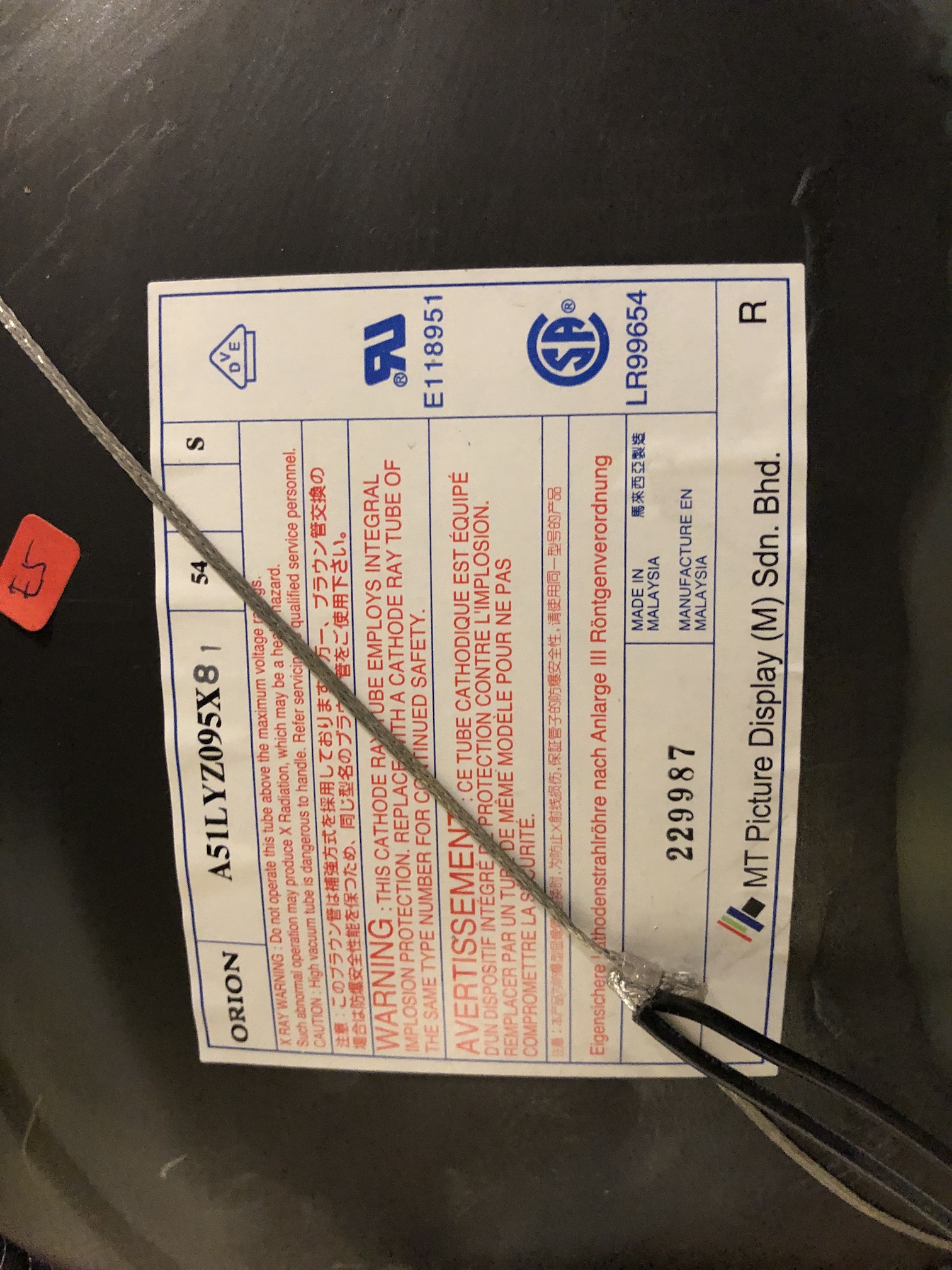
Back label 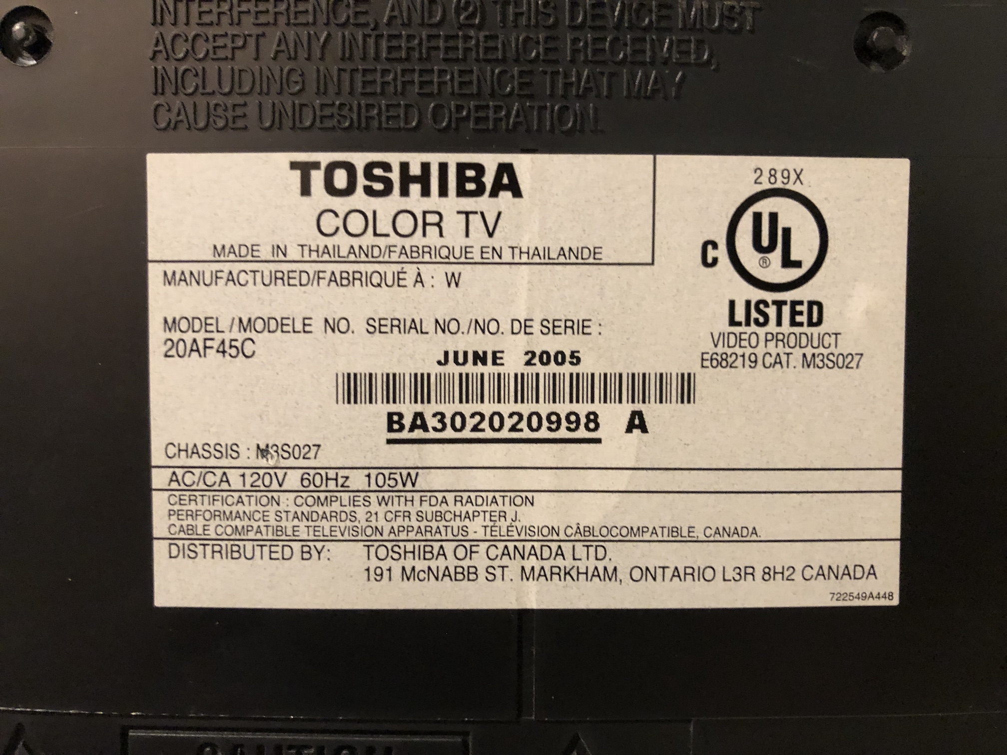
Back open 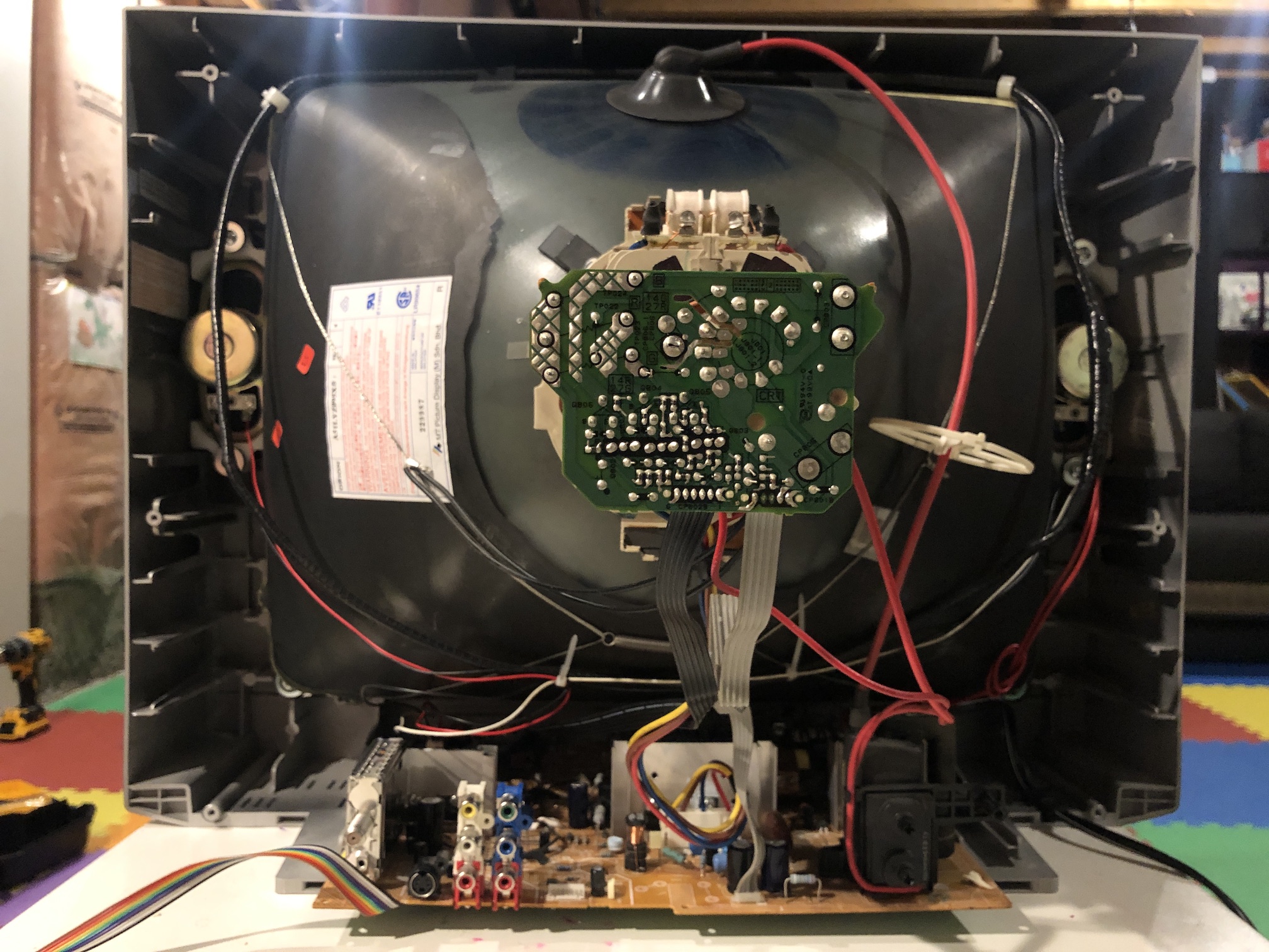
Pictures
Reference Photos