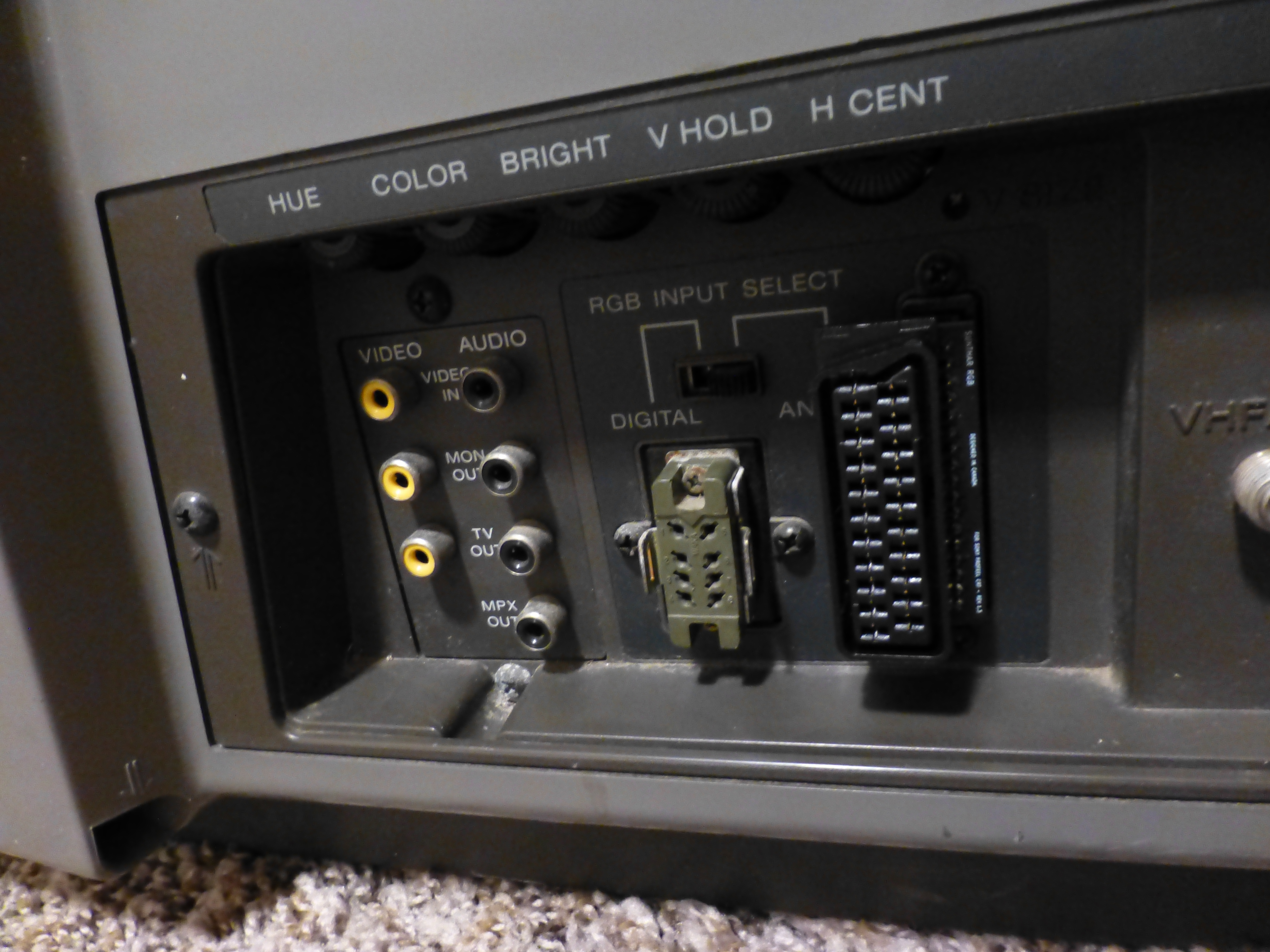
Sony Profeel/XBR Series
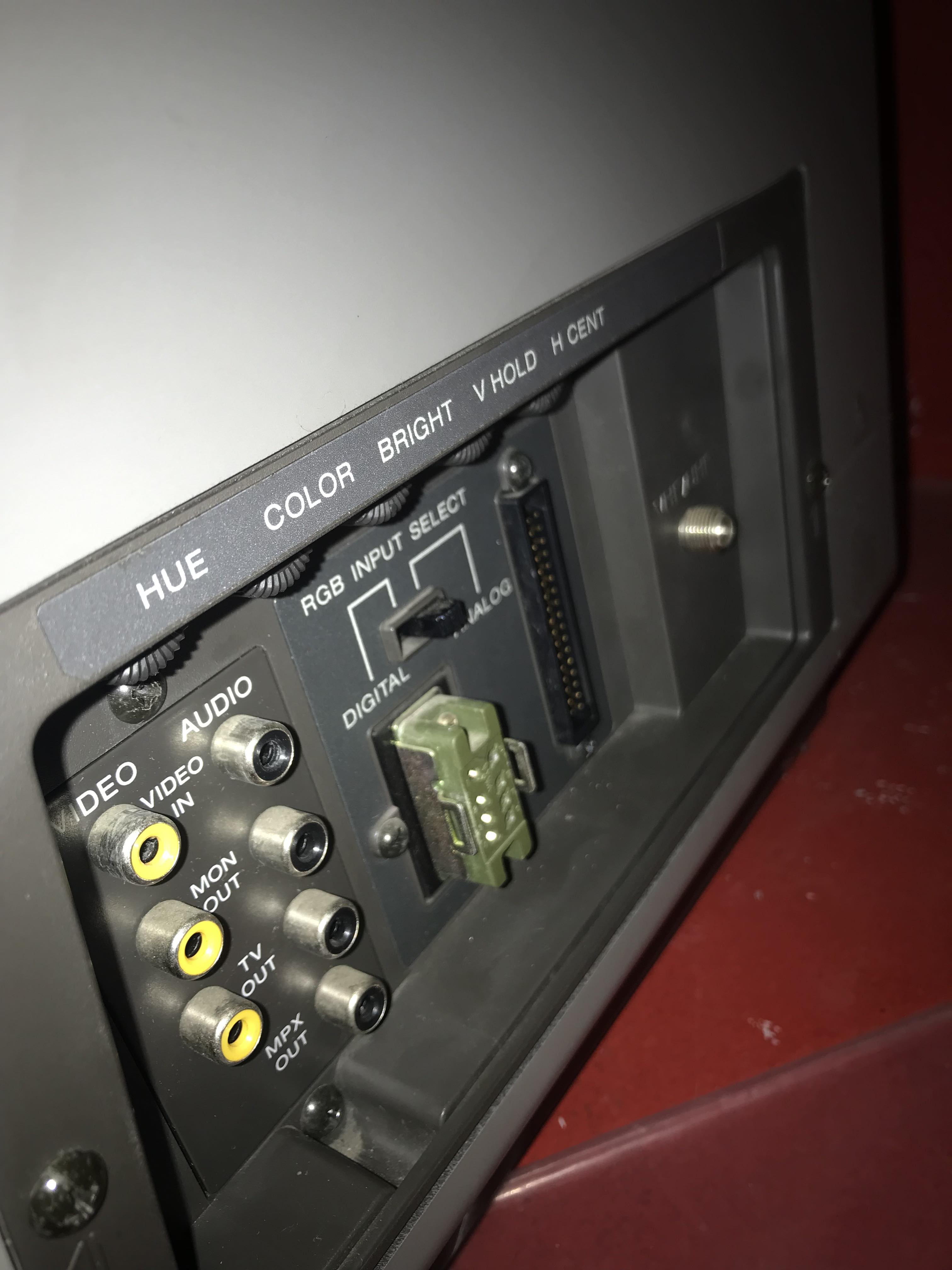
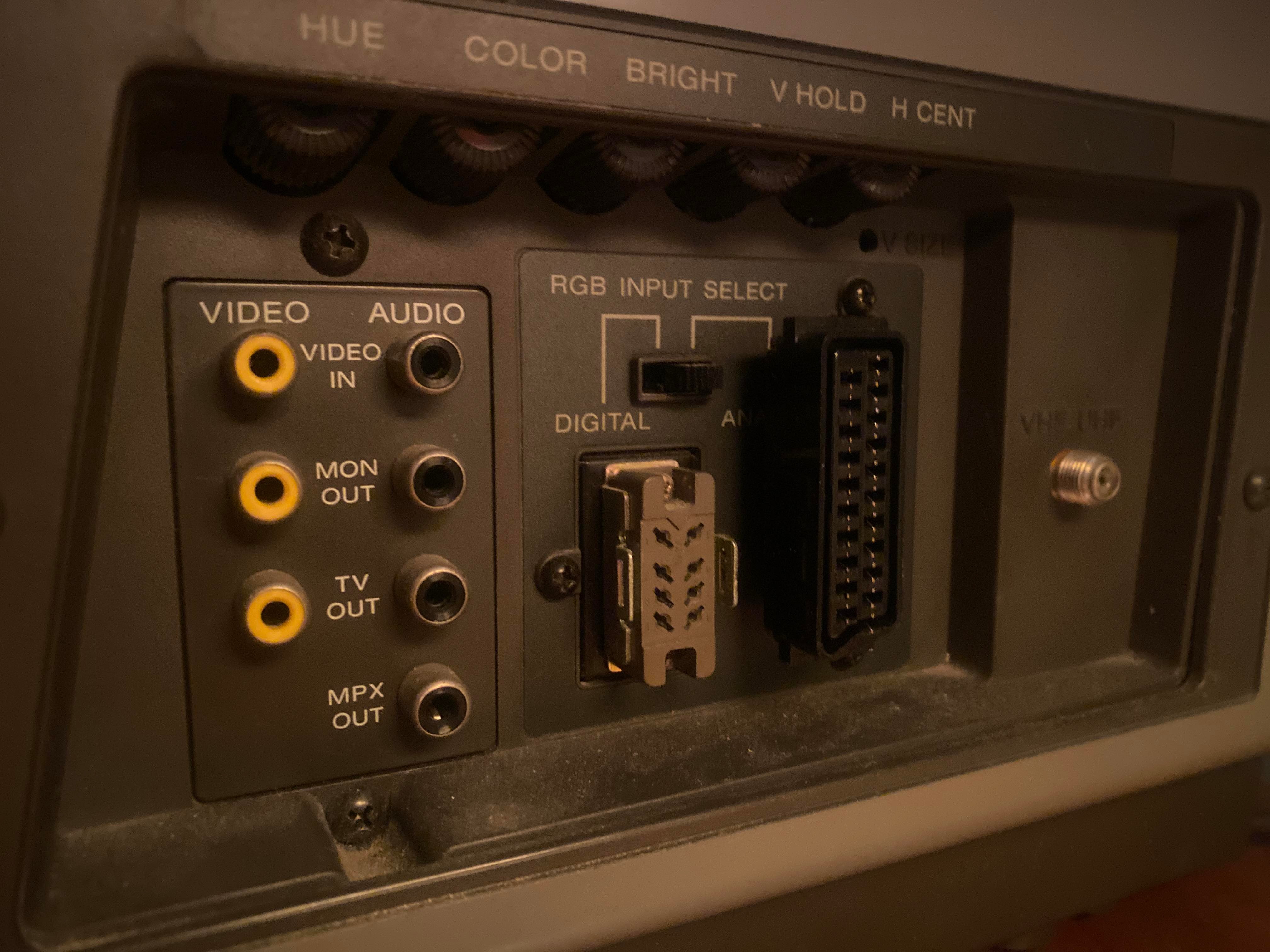
Feeding analog RGB signal through the 34-pin port
The following CRT televisions are confirmed to support analog RGB via the 34-pin port. My adapters are compatible with all of the models listed below.
- Sony KV-1311CR
- Sony KX-1901A
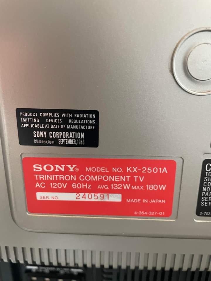
- Sony KX-2501A
- Sony KV-20XBR
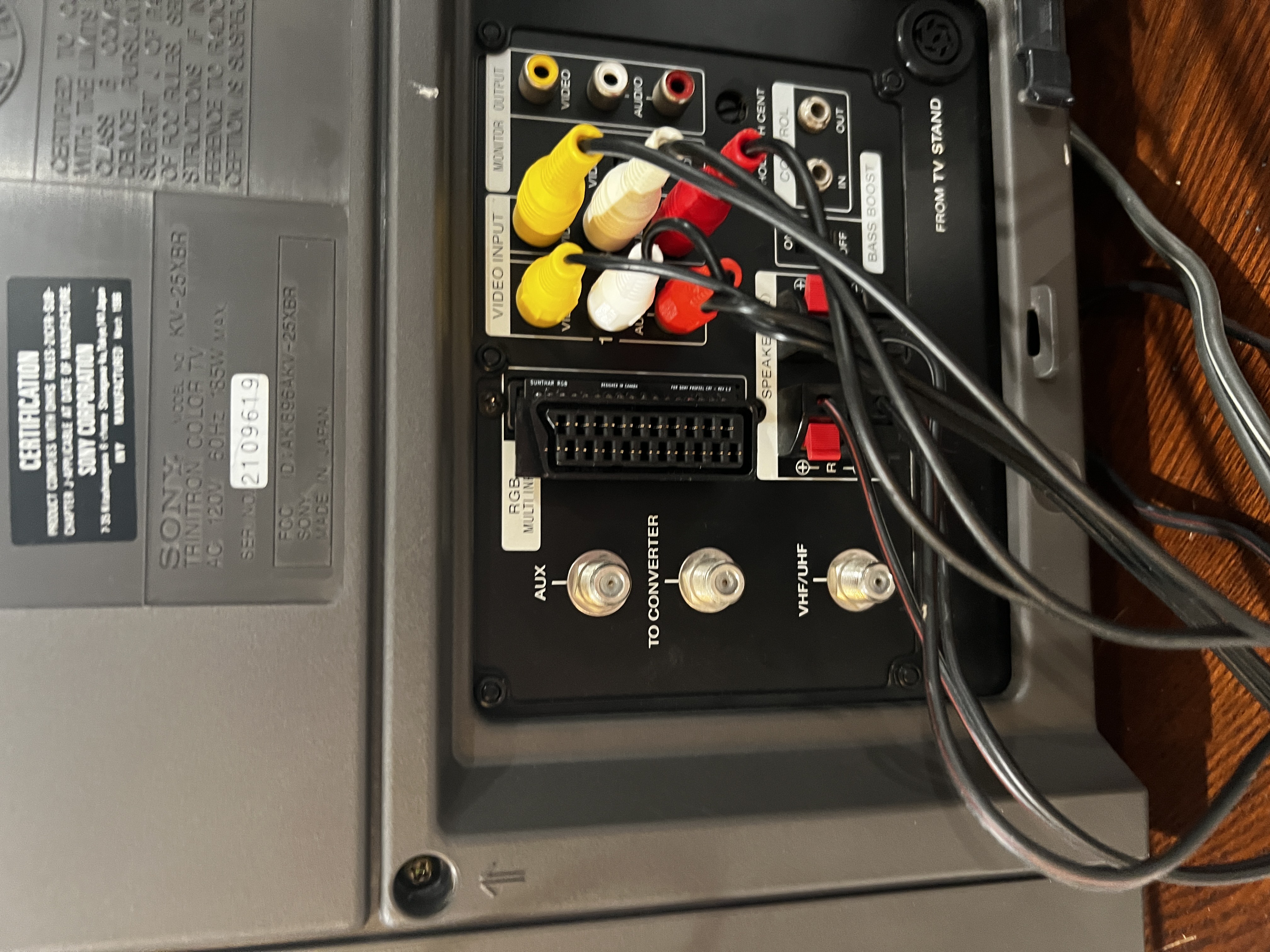
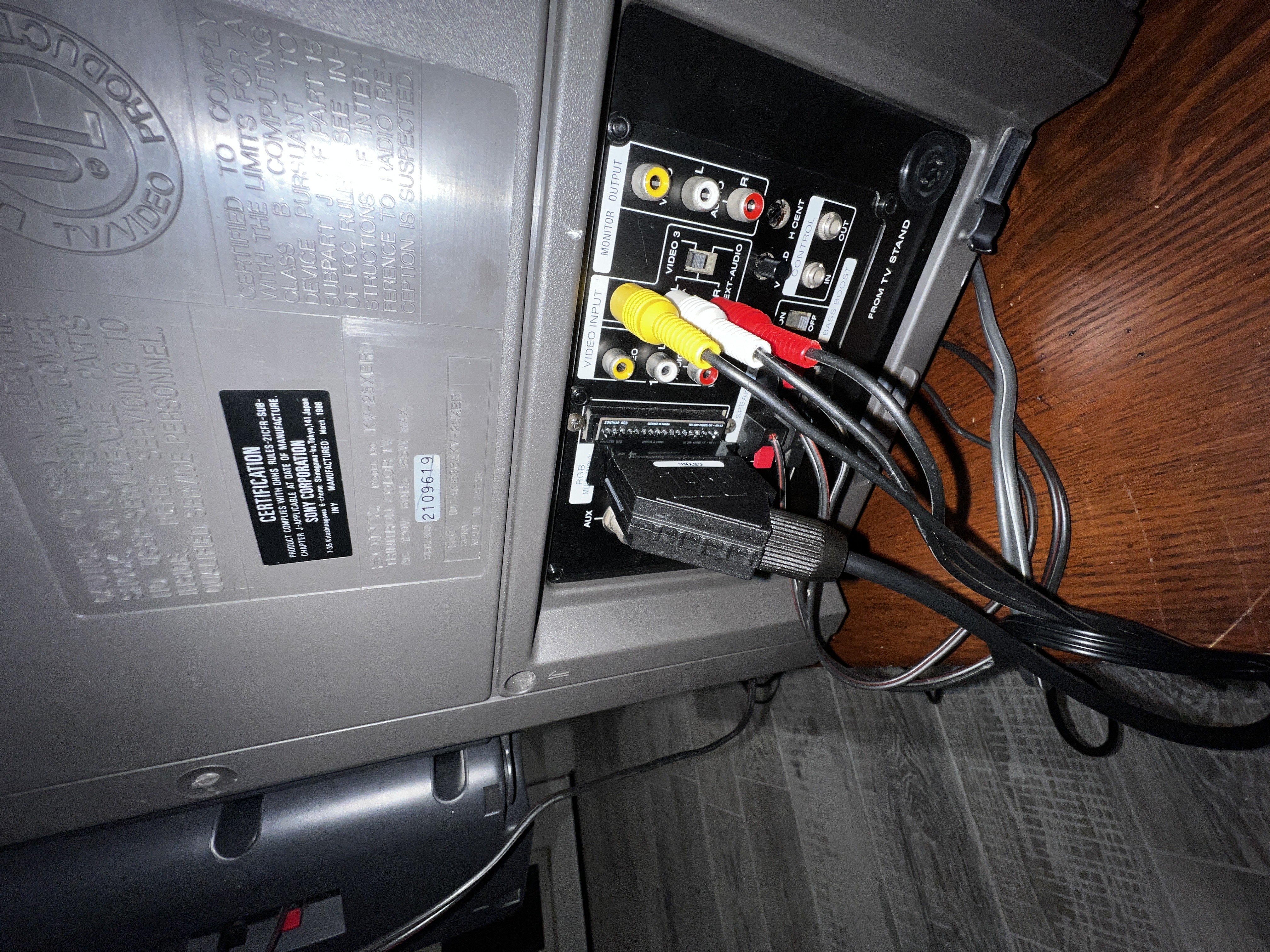
- Sony KV-25XBR
- Sony KV-25DXR
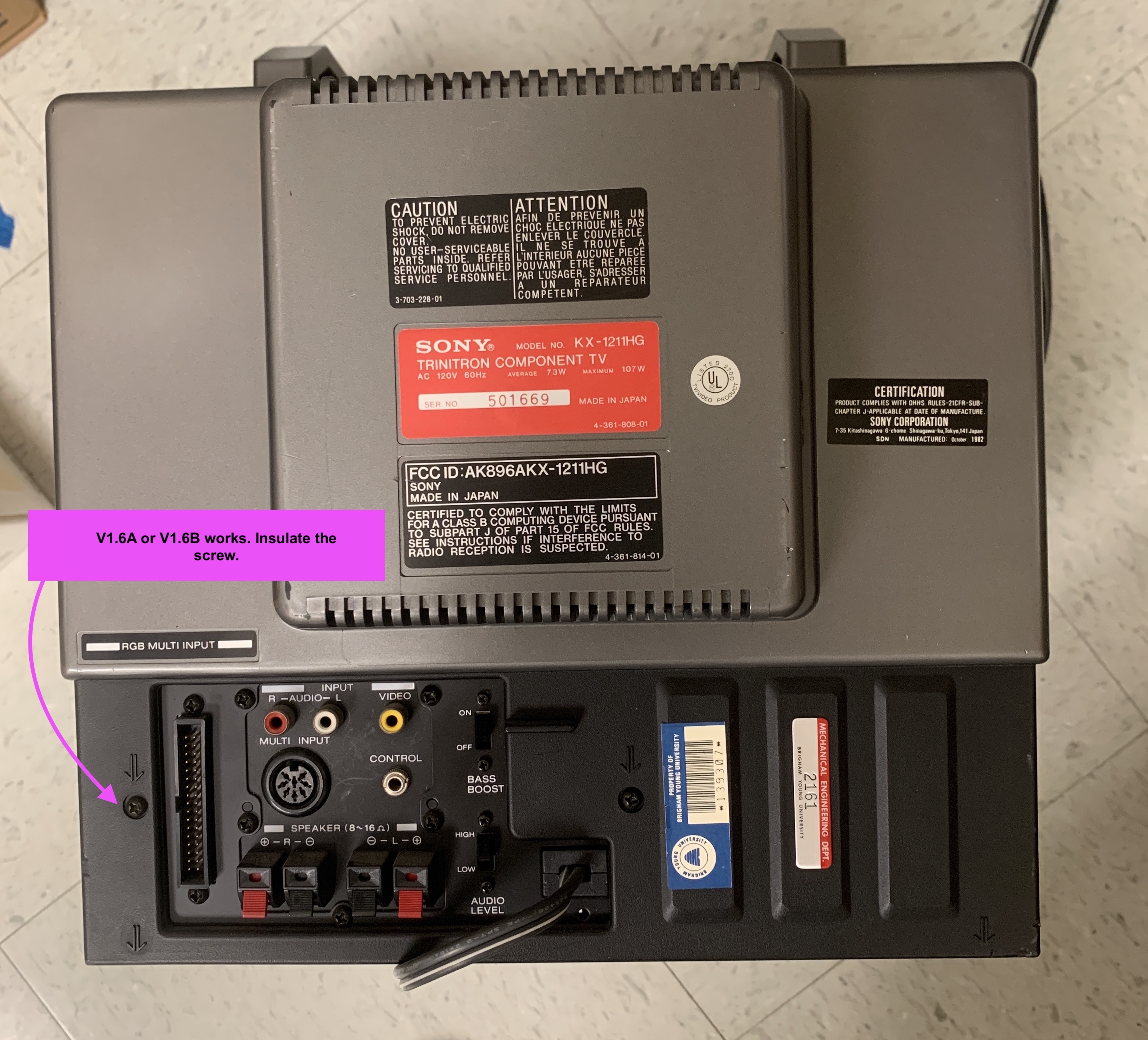
- Sony KX-1211HG
- Sony KX-13HG1
Below NEC models also have similar pinout as Sony Profeel sets
NOT SUPPORTED MODELS
- Sony KX-1901, Sony KX-2501 does not support analog RGB, only digital RGB. However, if you have the later revision Sony KX-1901A or Sony KX-2501A CRT, then you are good. "A" at the end of the model # here apparently stands for "Analog" support. Using the RGB Multi to SCART adapter on non-"A" version will not be that useful for retro gaming purposes.
- Sony KX-20PS1, Sony KX-27PS1 does not support analog RGB based on our tests. You can use the Peri-TV input and the 34pin input for digital RGB inputs.
If you feed analog RGB to digital RGB input you might see colors that are flat, missing or corrputed.
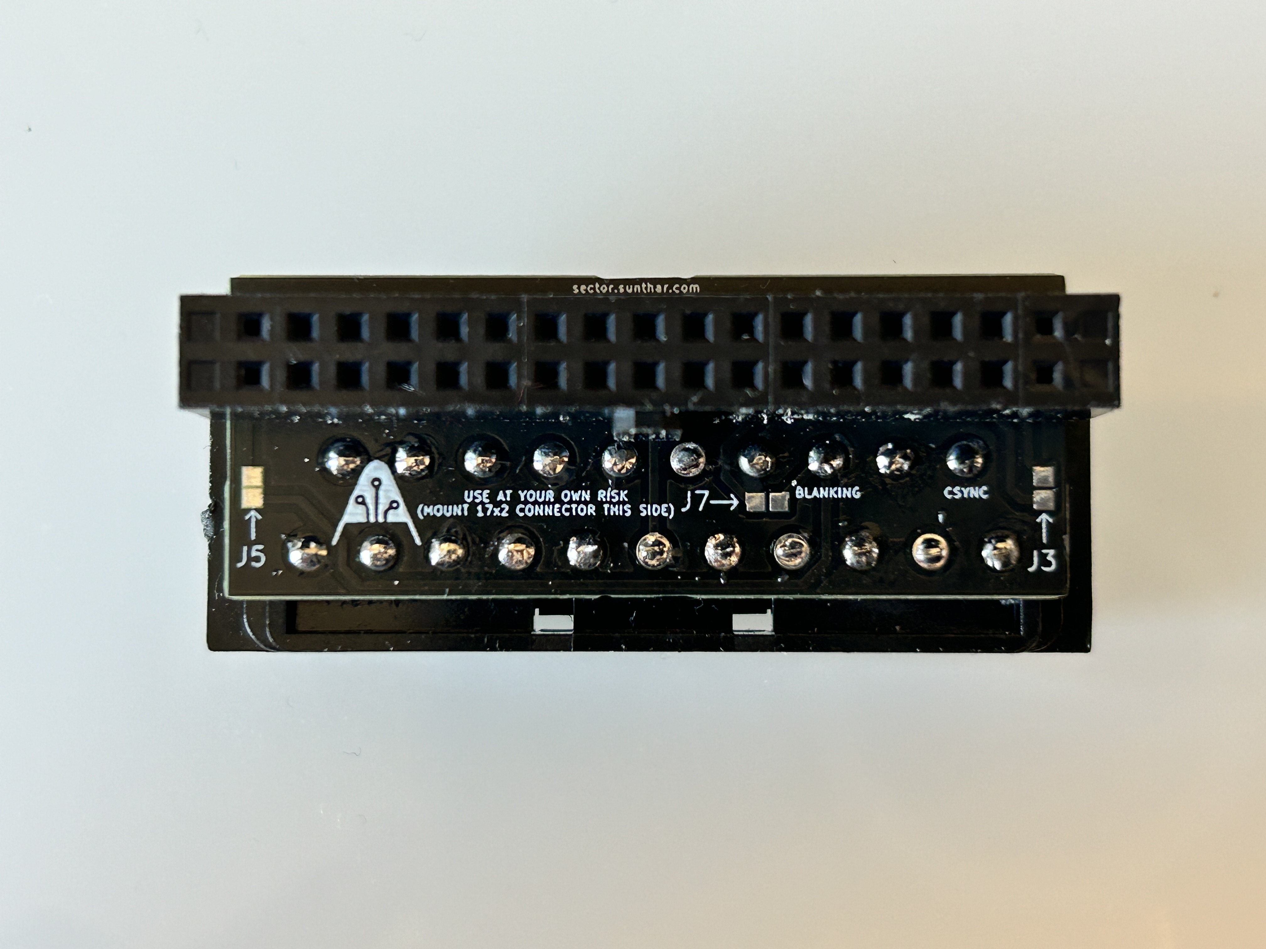
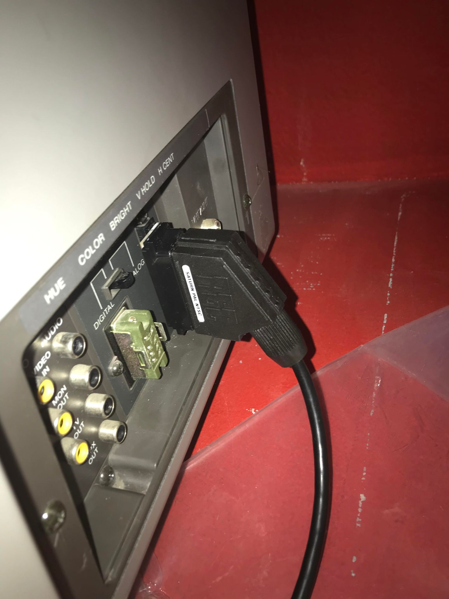
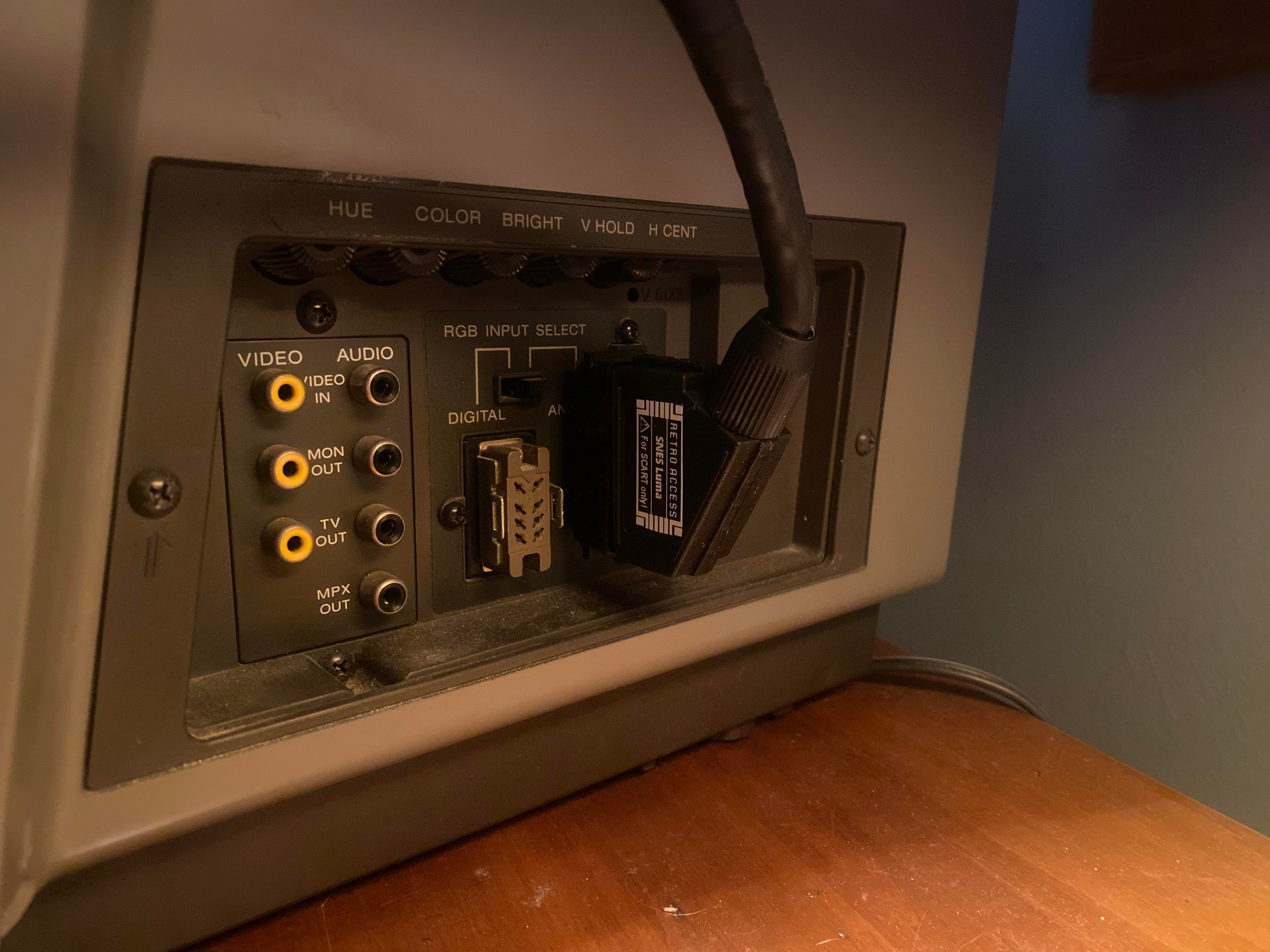
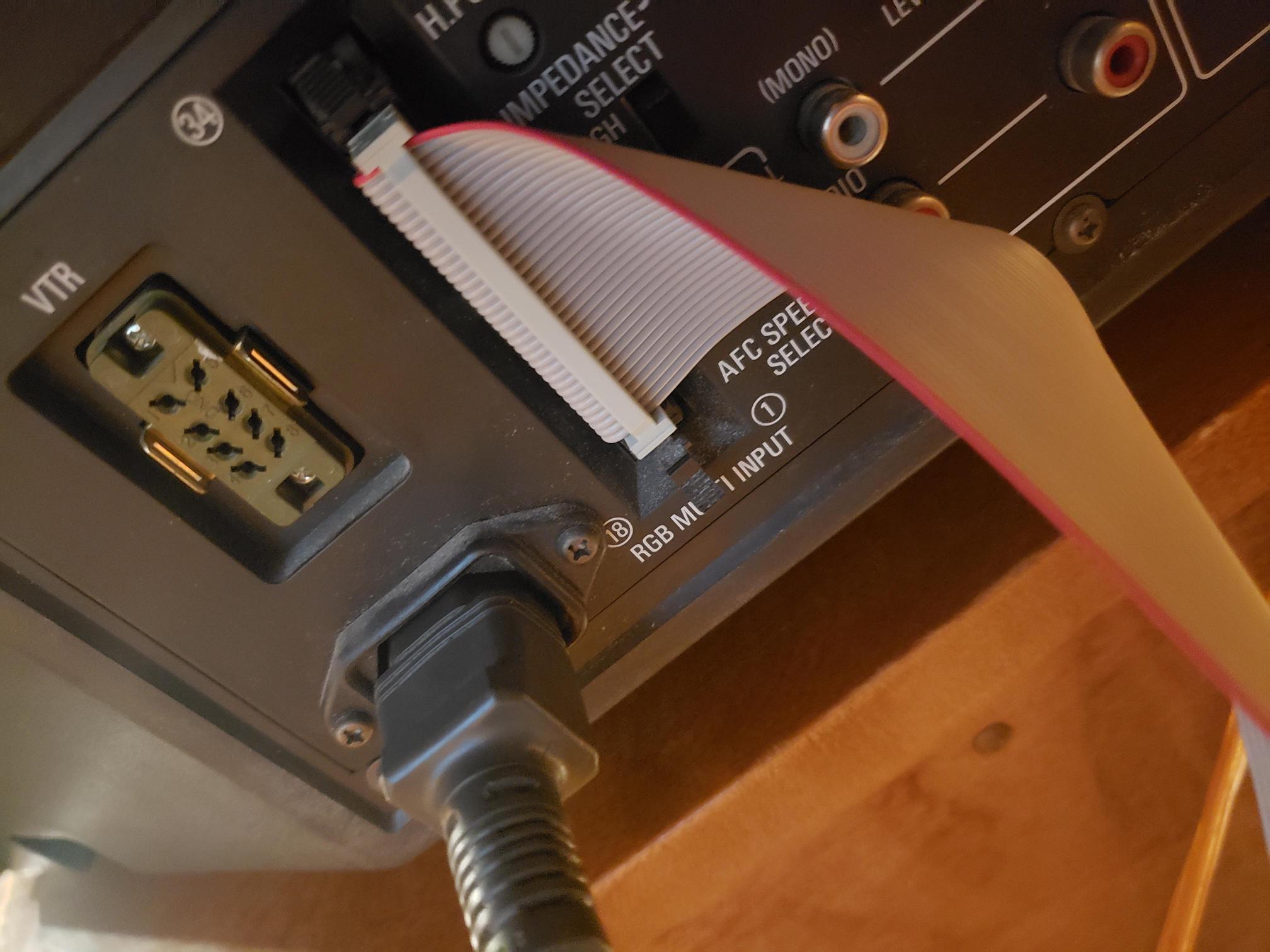
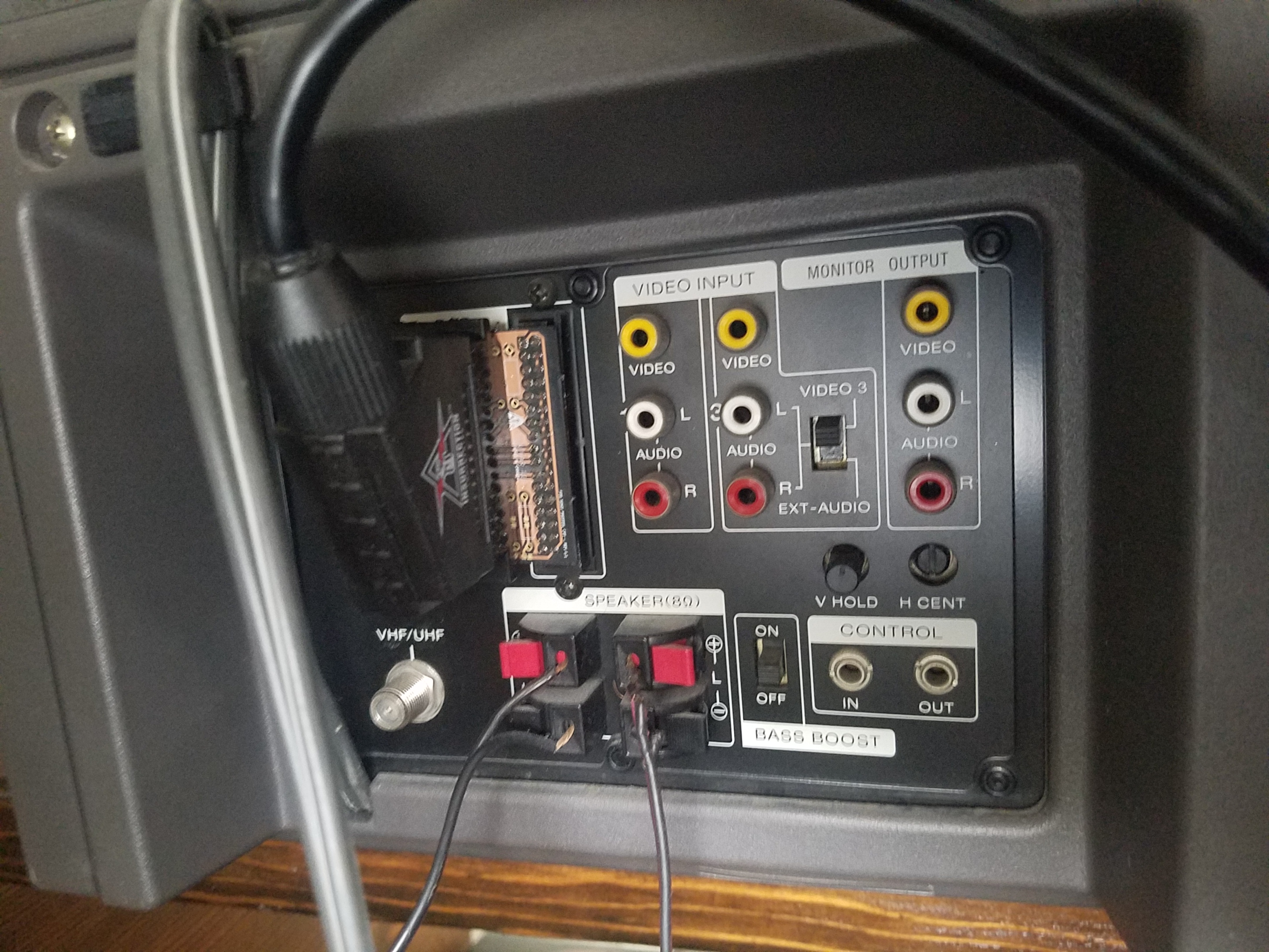
34 Pin RGB/SCART Adapter
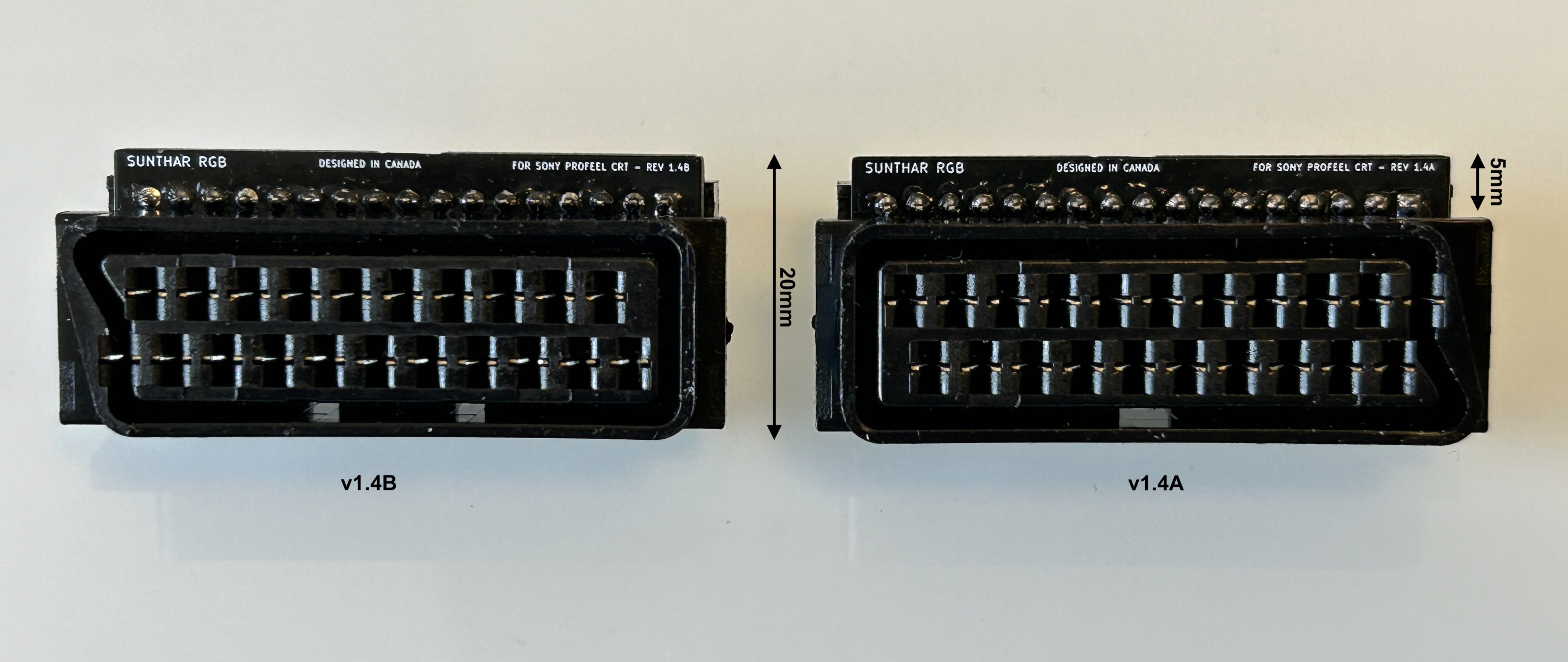 New and improved adapter is only 2cm wide, making it possible to use without an extension cable for most sets.
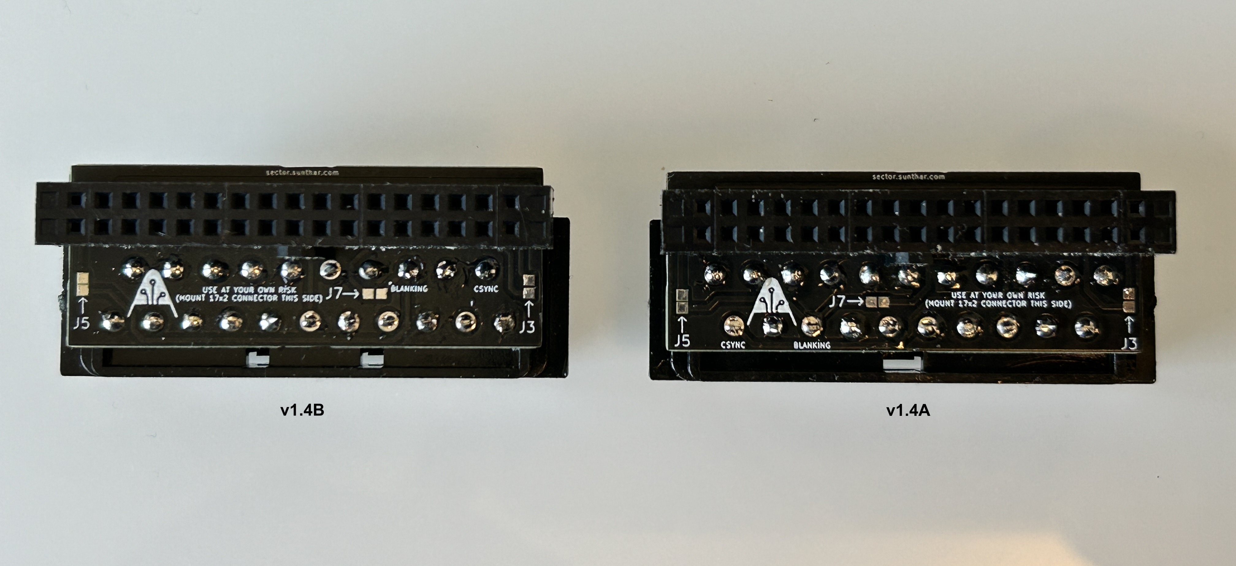
Two different adapters are available depending on the orientation you prefer for the cable and your set. However, no need to fret. Just provide me with the model number of your set when placing the order and I will take care of the rest.
- KV-1311CR (v1.6C keeps the SCART cable pointing downwards, J5 soldered and two resistors added for mono audio)
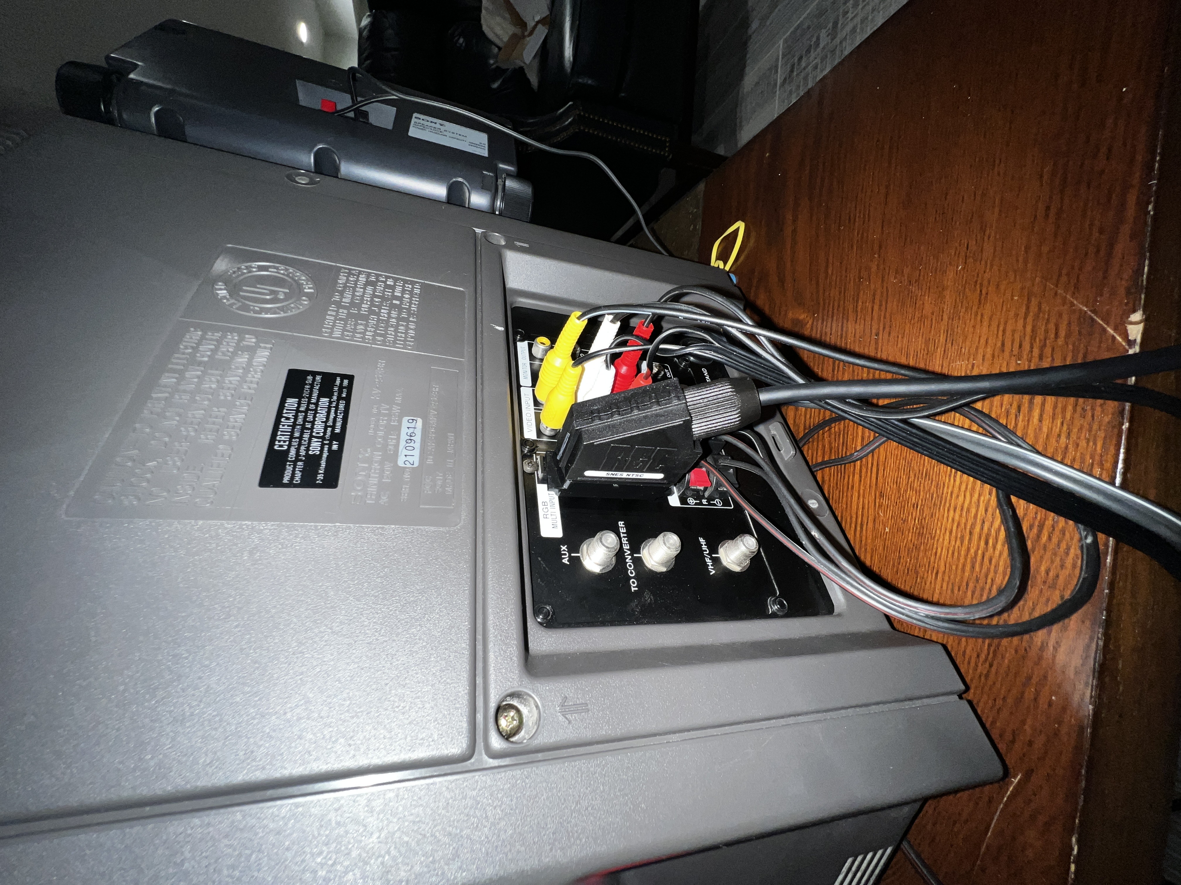
- Sony KV-25XBR (v1.6B keeps the SCART cable pointing downwards)
- Sony KX-1901A (v1.6B or v1.6A)
- Sony KX-2501A (v1.6A)
- Sony KX-1211HG (1.6B, tight clearance for SCART cable - may need to raise the CRT by an inch)
- NEC CM2591A (v1.6B keeps the SCART cable pointing downwards)
If you're placing an order for the adapter, kindly send me your CRT model number and, if possible, include a photo of the back of your set to ensure you receive the correct version of the board with the appropriate jumpers soldered.
Buy the adapter
Service Manuals
- Sony KX-1901A
- Sony KX-2501A
- Sony KV-1311CR
- Sony KV-20XBR
- Sony KV-25XBR
- Sony KV-25DXR
- Sony KX-1211HG
- NEC CM2591A
Shifting the RGB image using an external shifter
If your CRT doesn't provide an easier way to shift the RGB image, you can use an external RGB shifter.
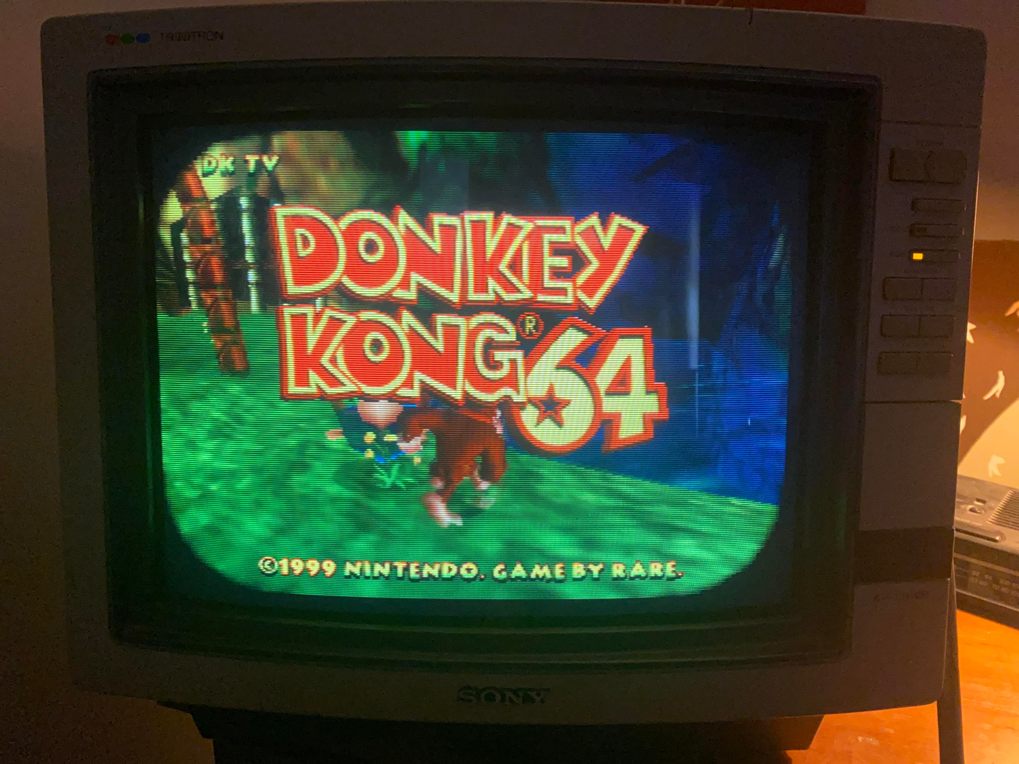
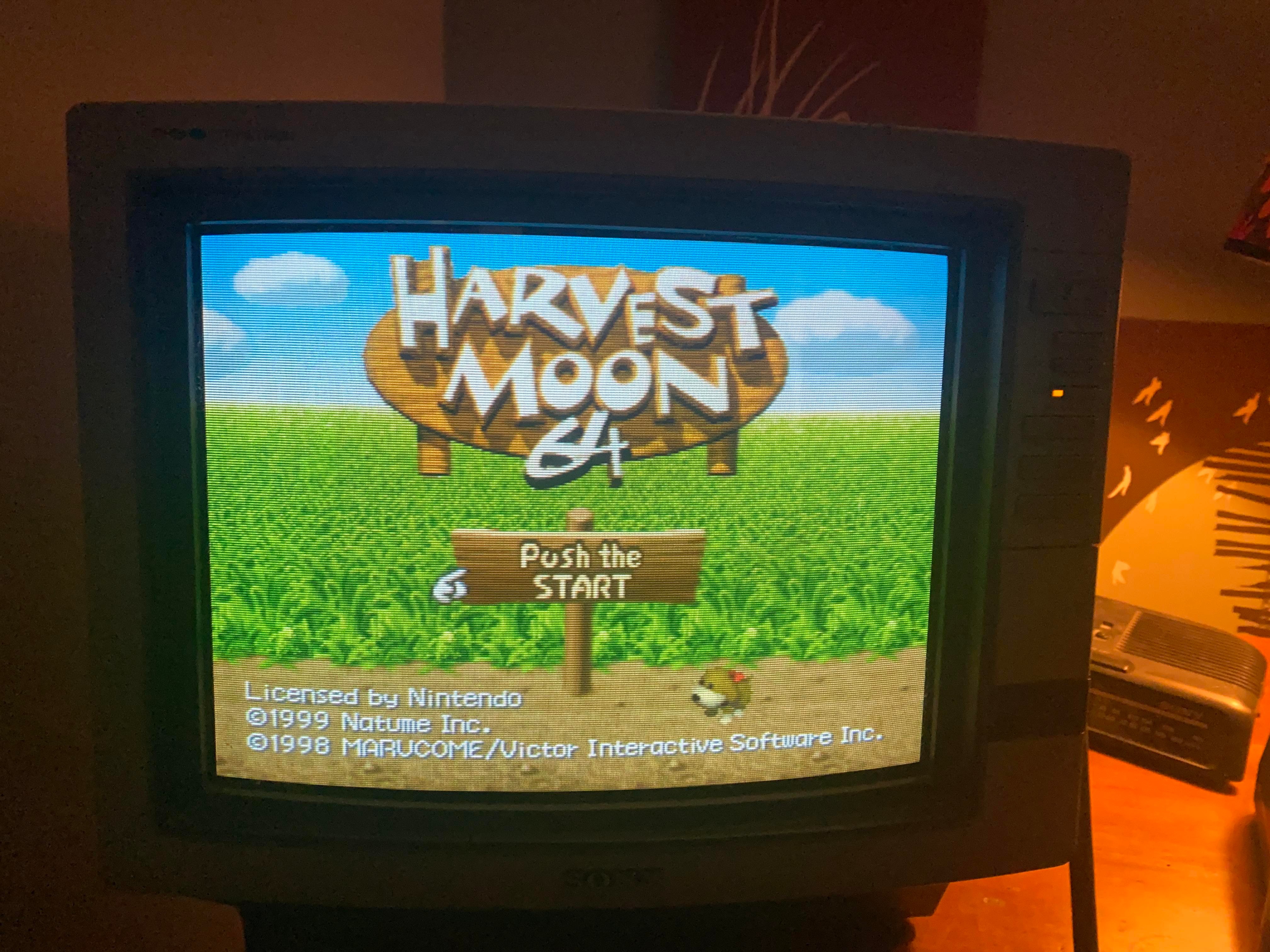
Pictures
Adapter
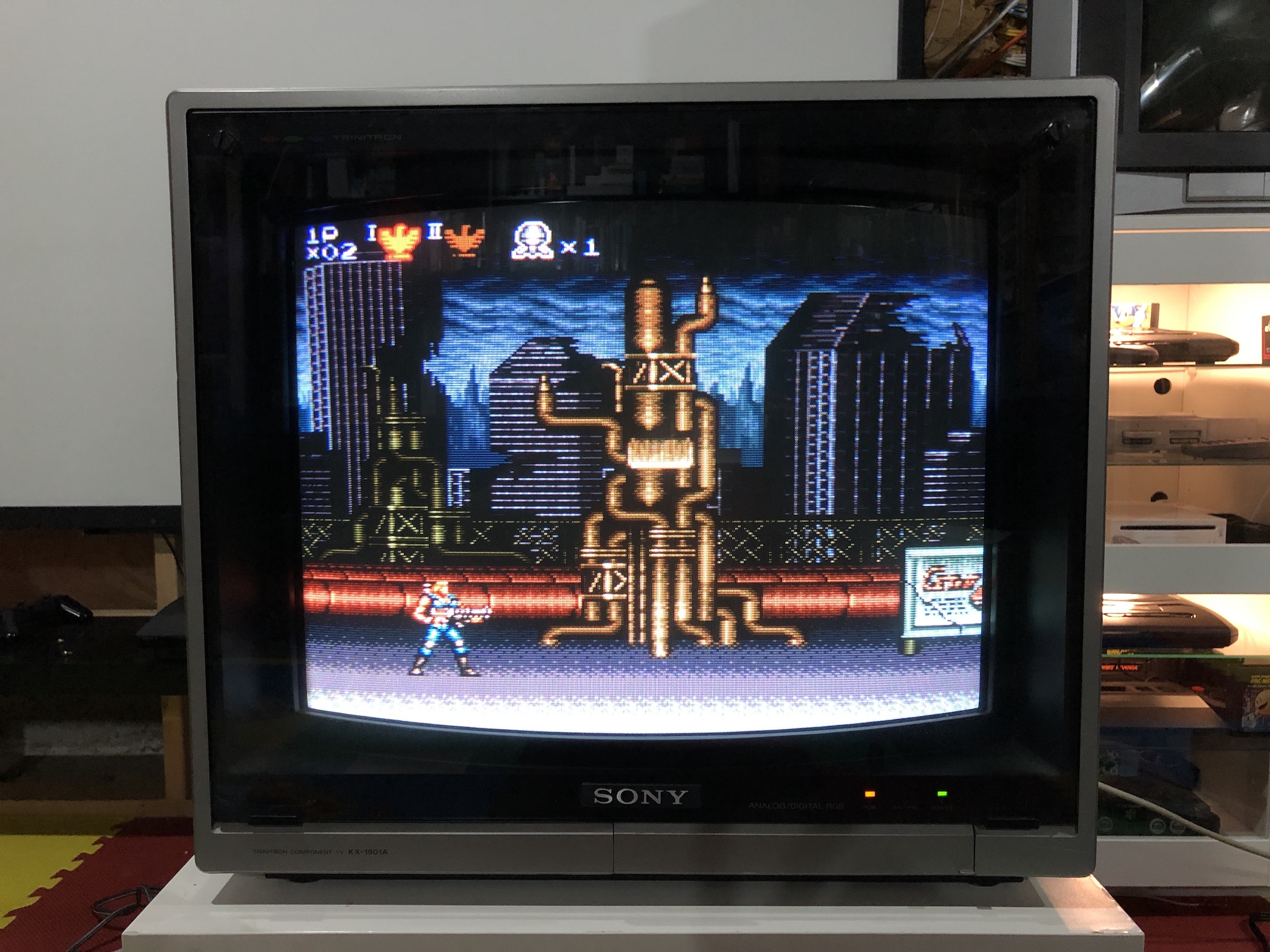
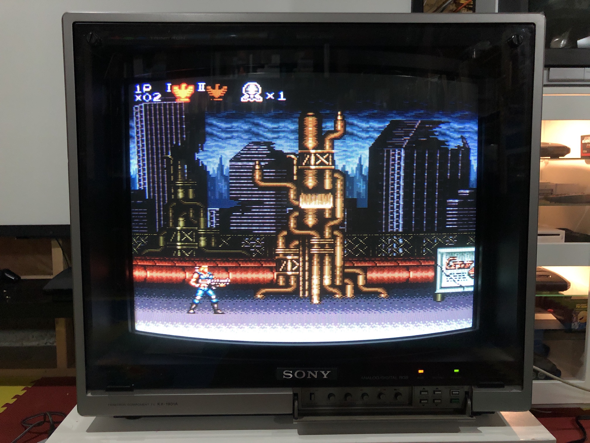
KX-1901A
Works as plug and play. Both 1.6A and 1.6B should work well.
Adapter on Sony Profeel KX-1901A. 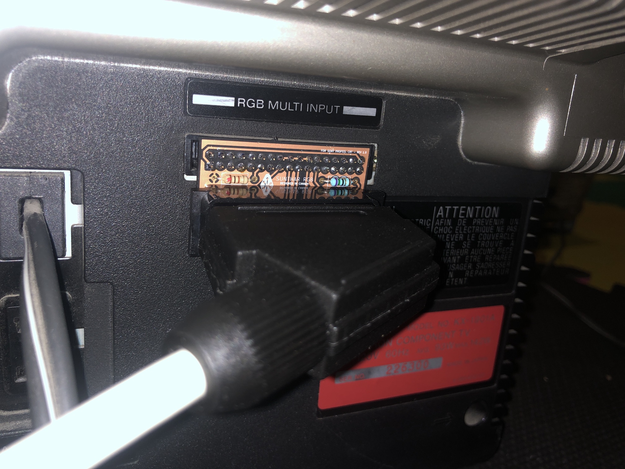
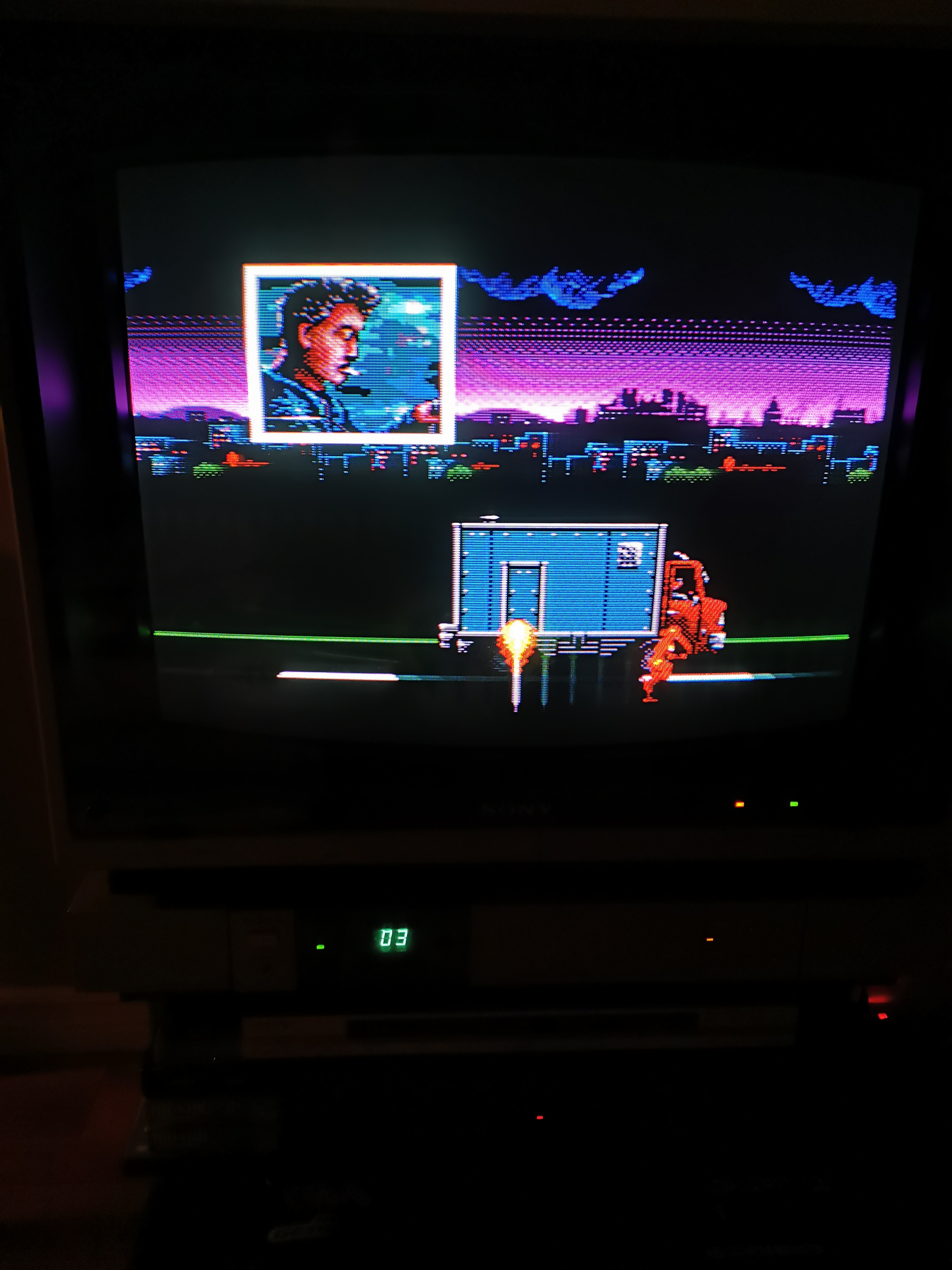
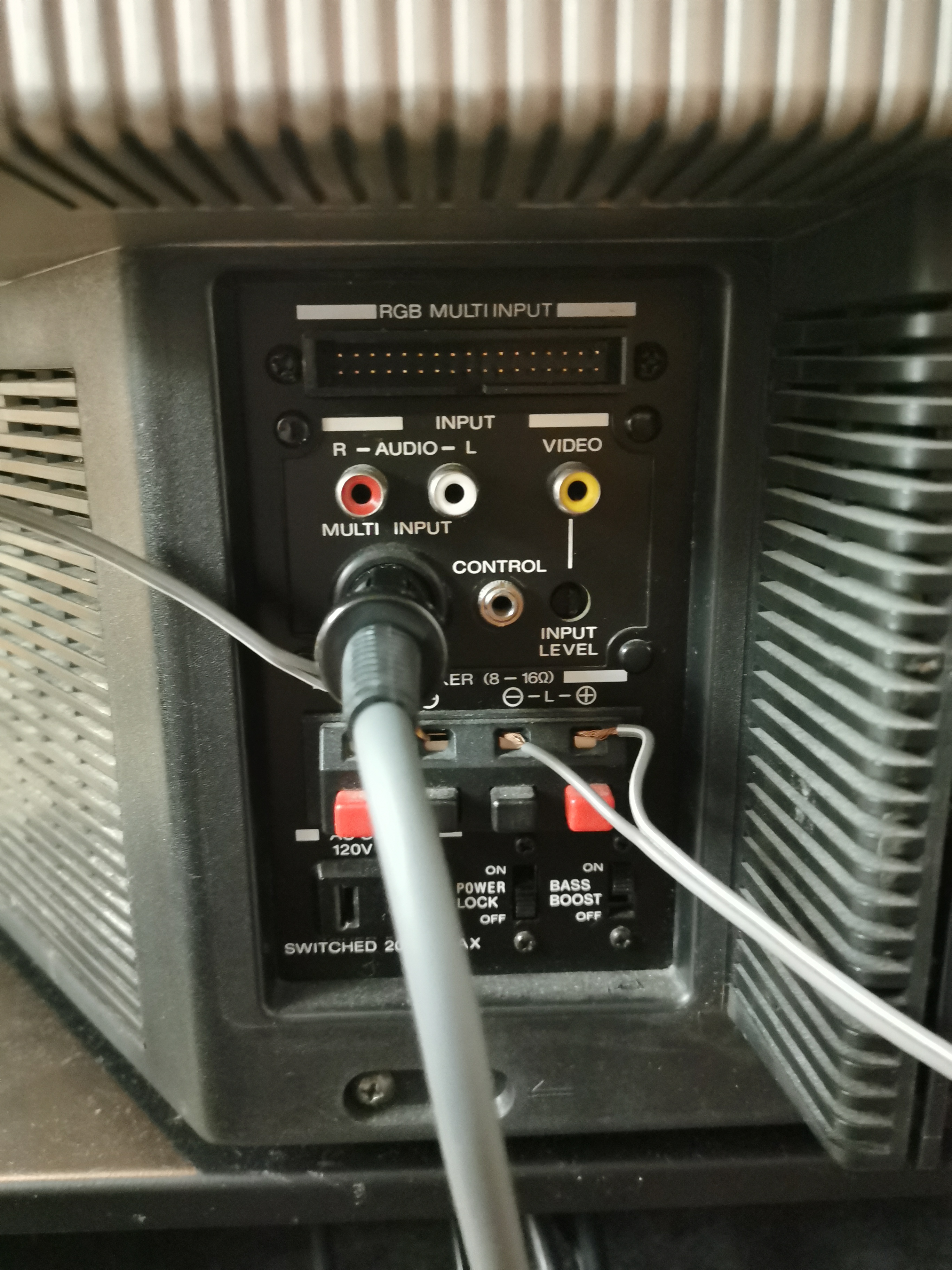
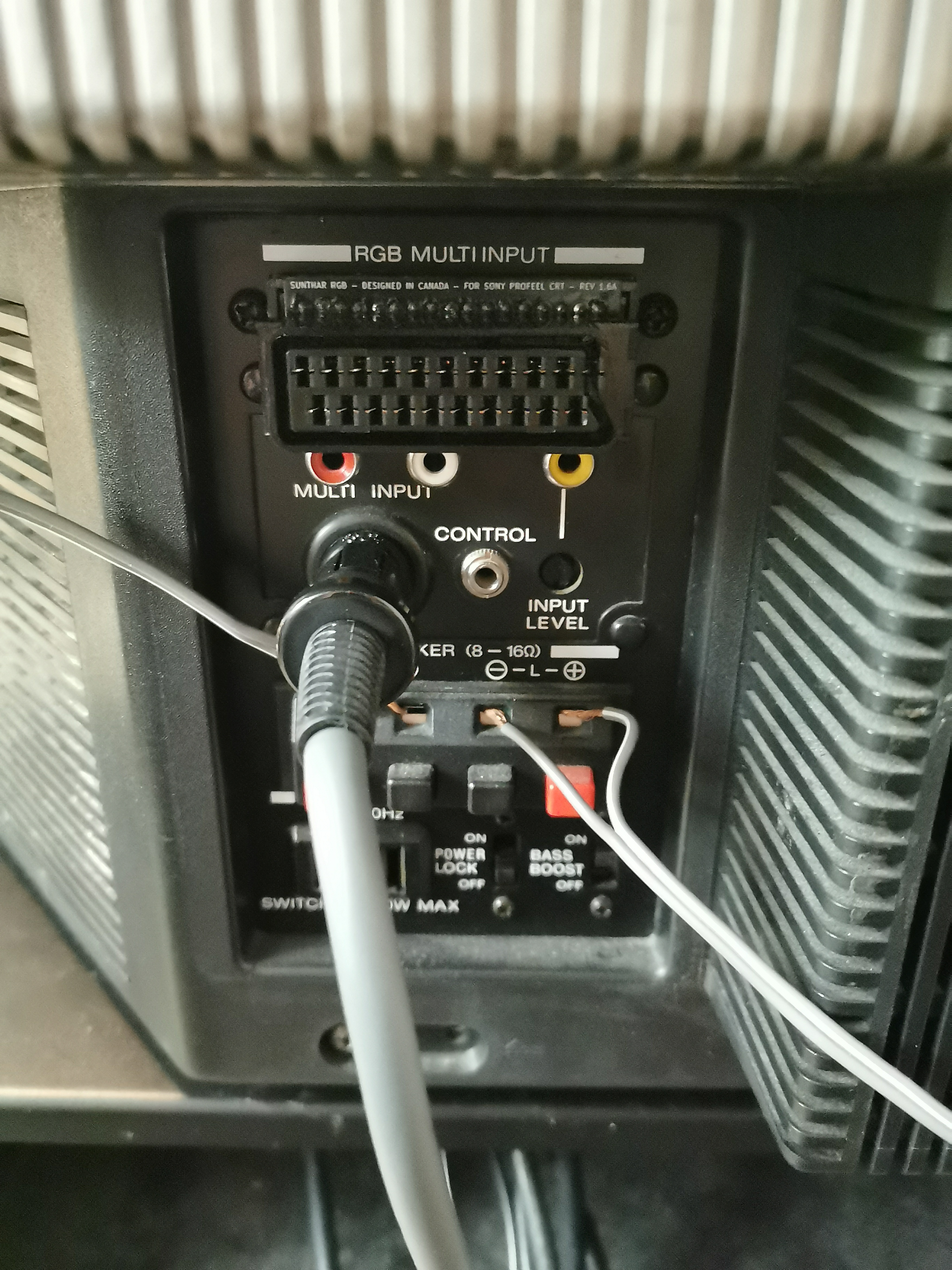
KX-2501A
Works as plug and play. 1.6A recommended.
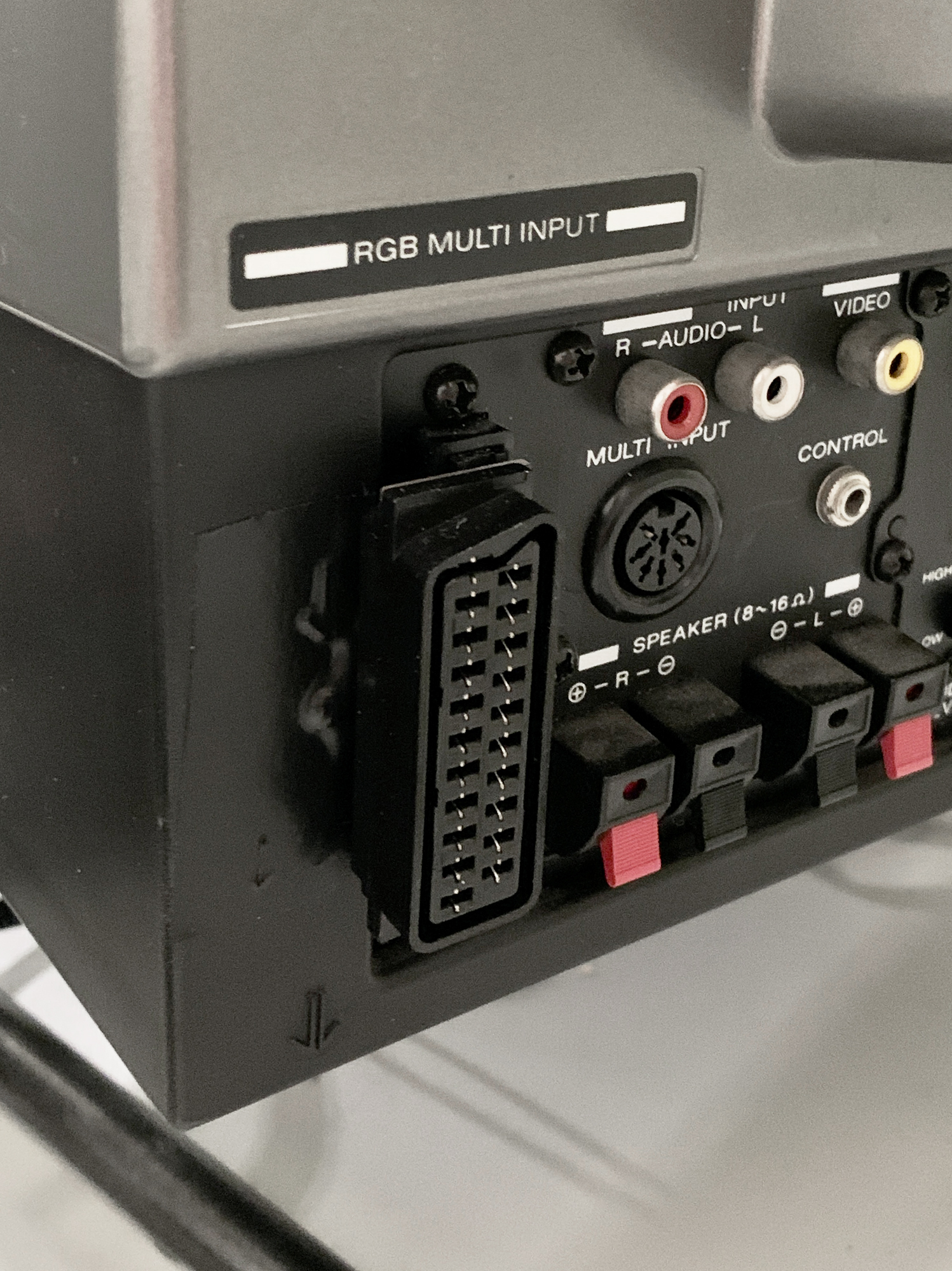
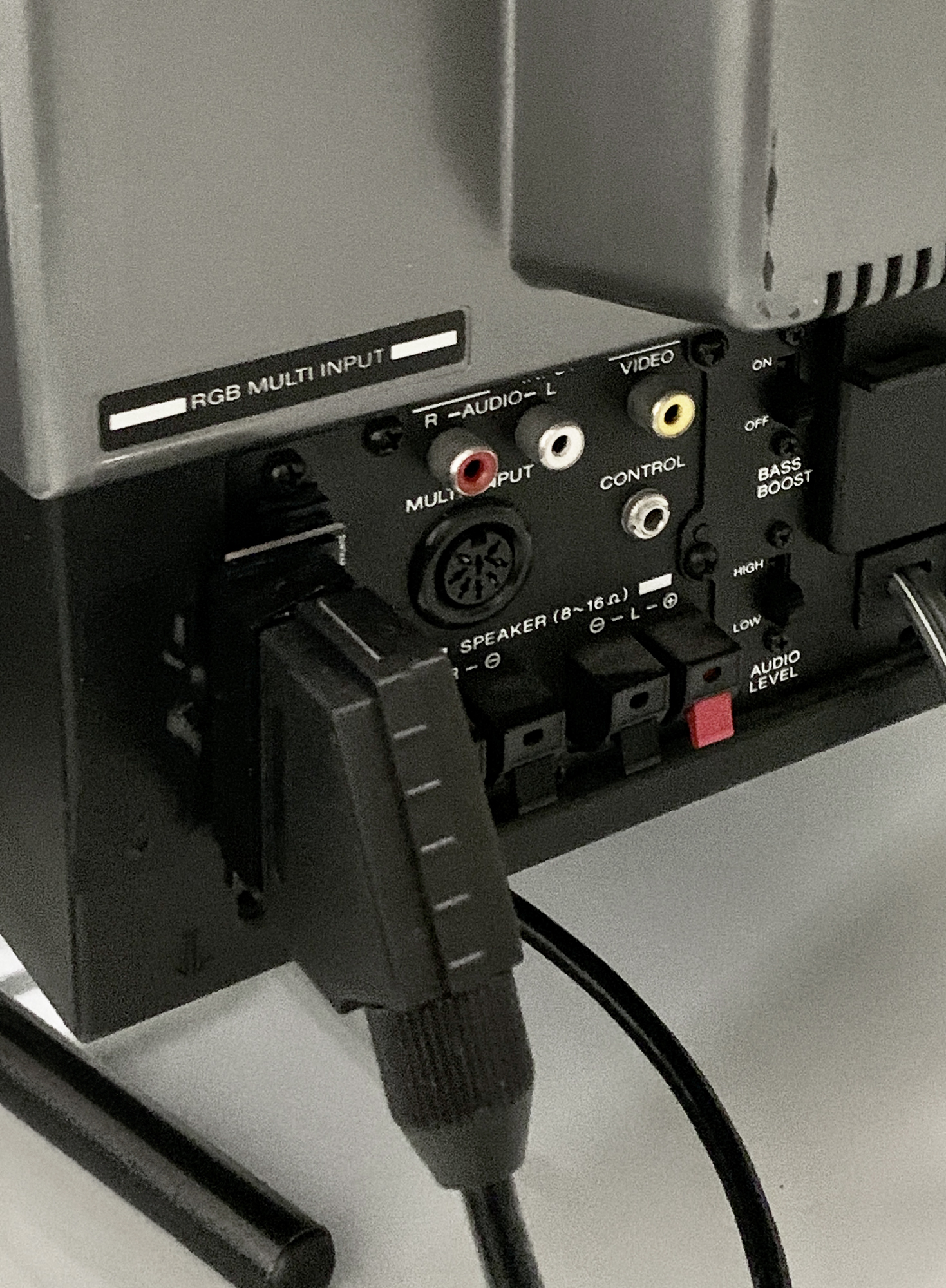
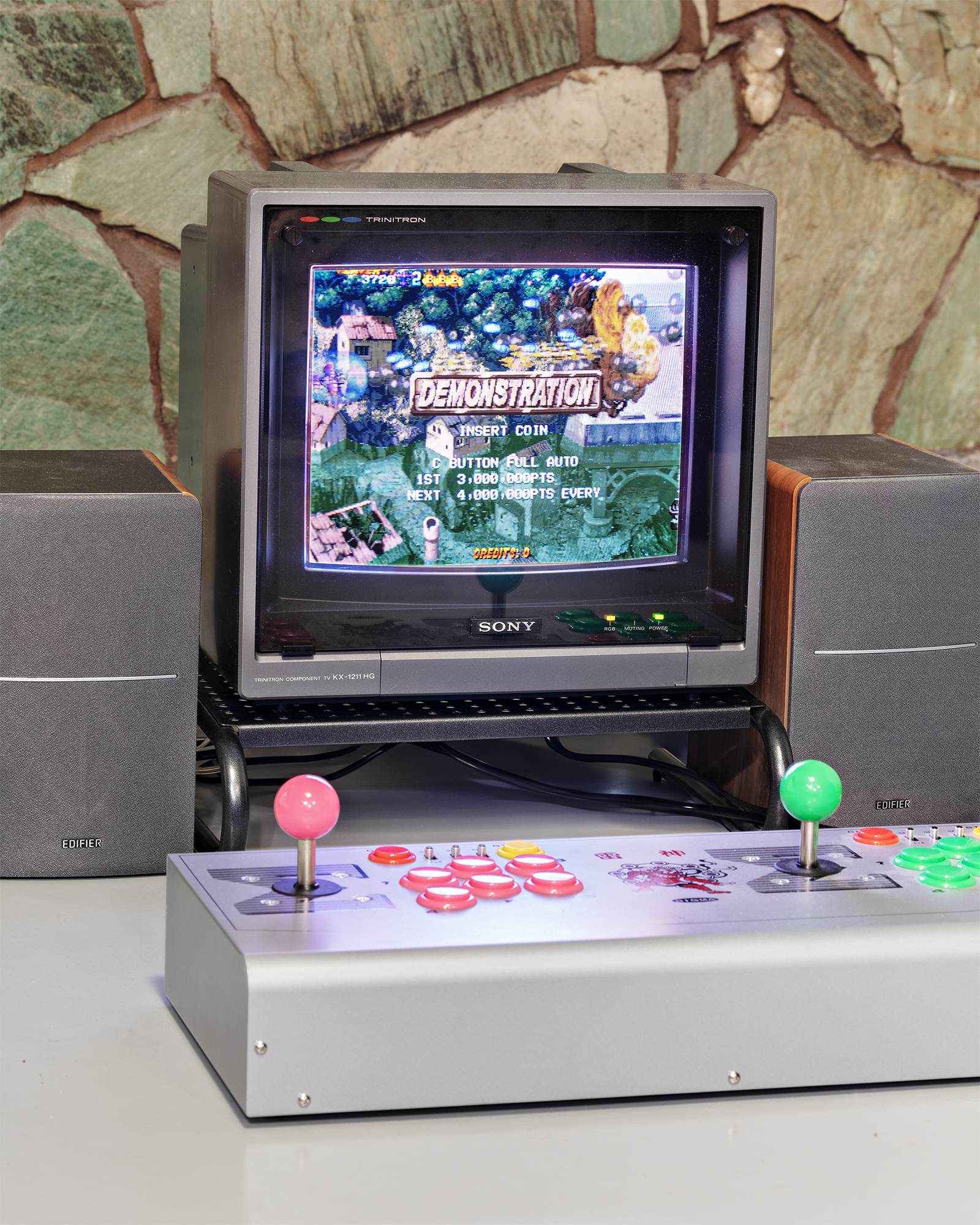
KX-1211HG
1.6B or 1.6A should work as a plug-and-play device. Below pictures show 1.6B, where the cable is pointing downwards. With 1.6A cable will be pointing upwards.
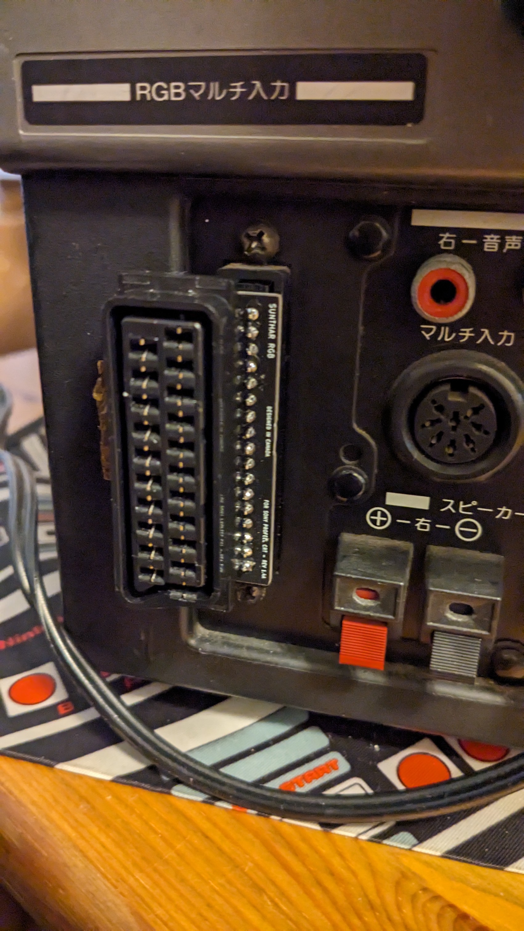
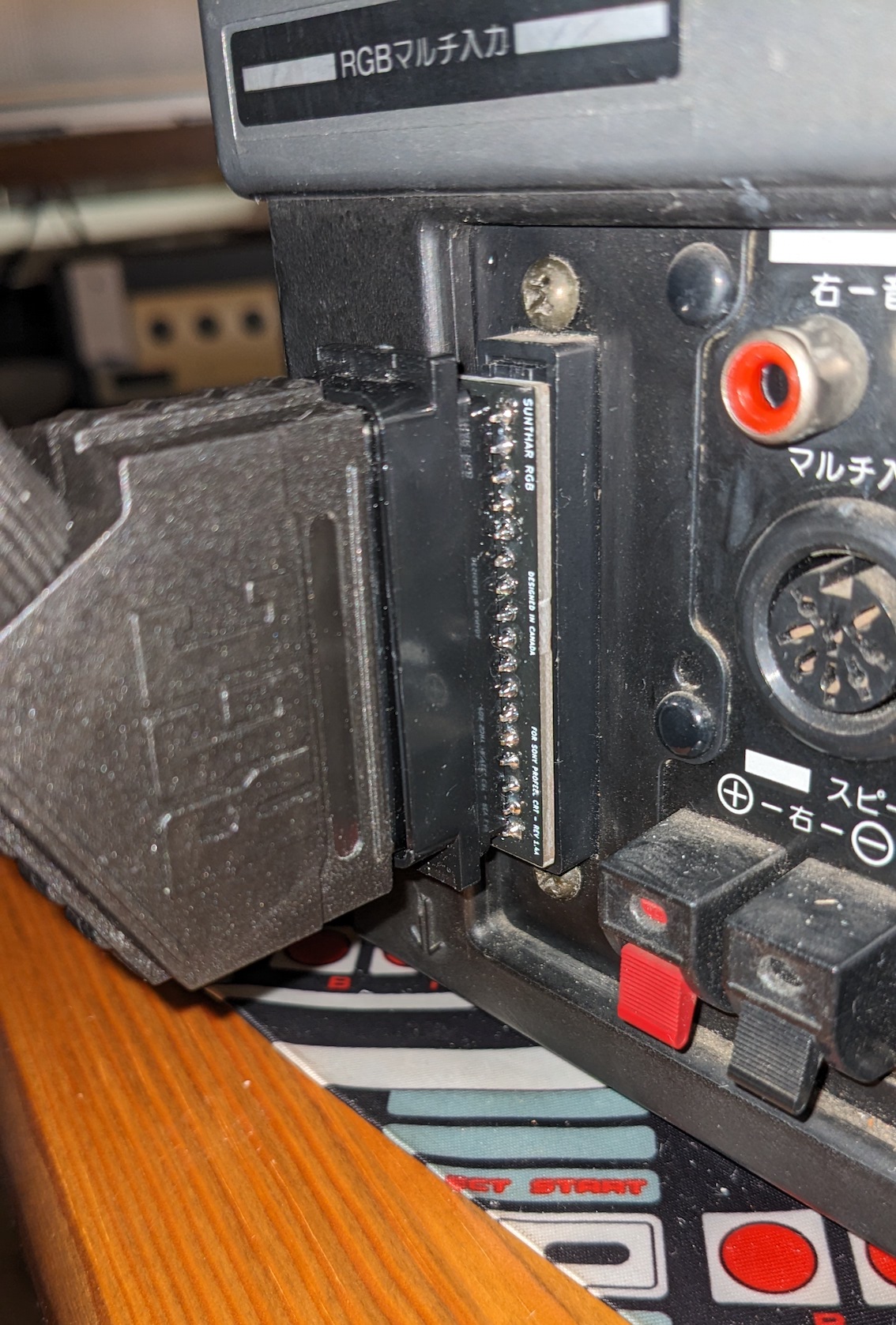
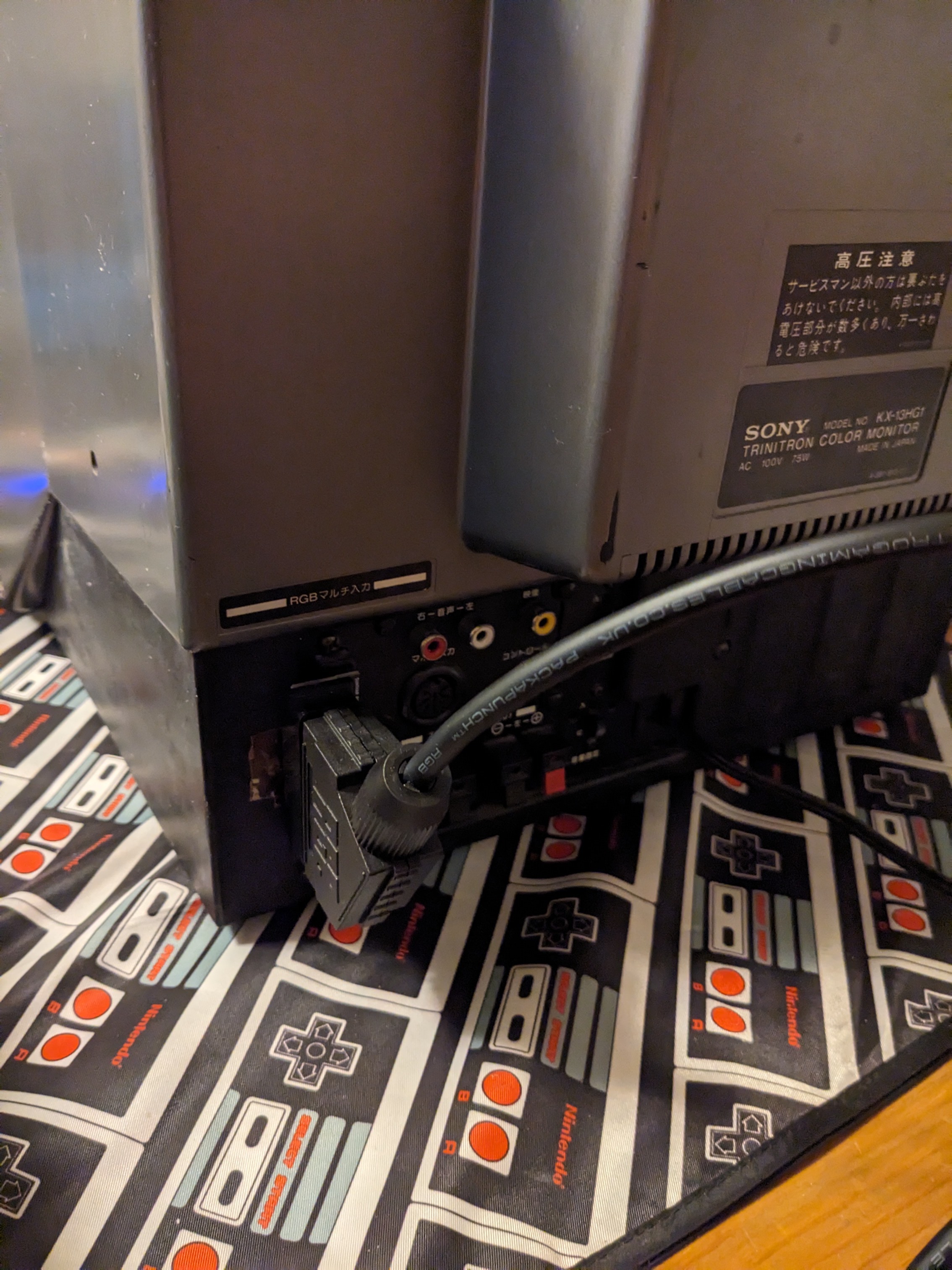
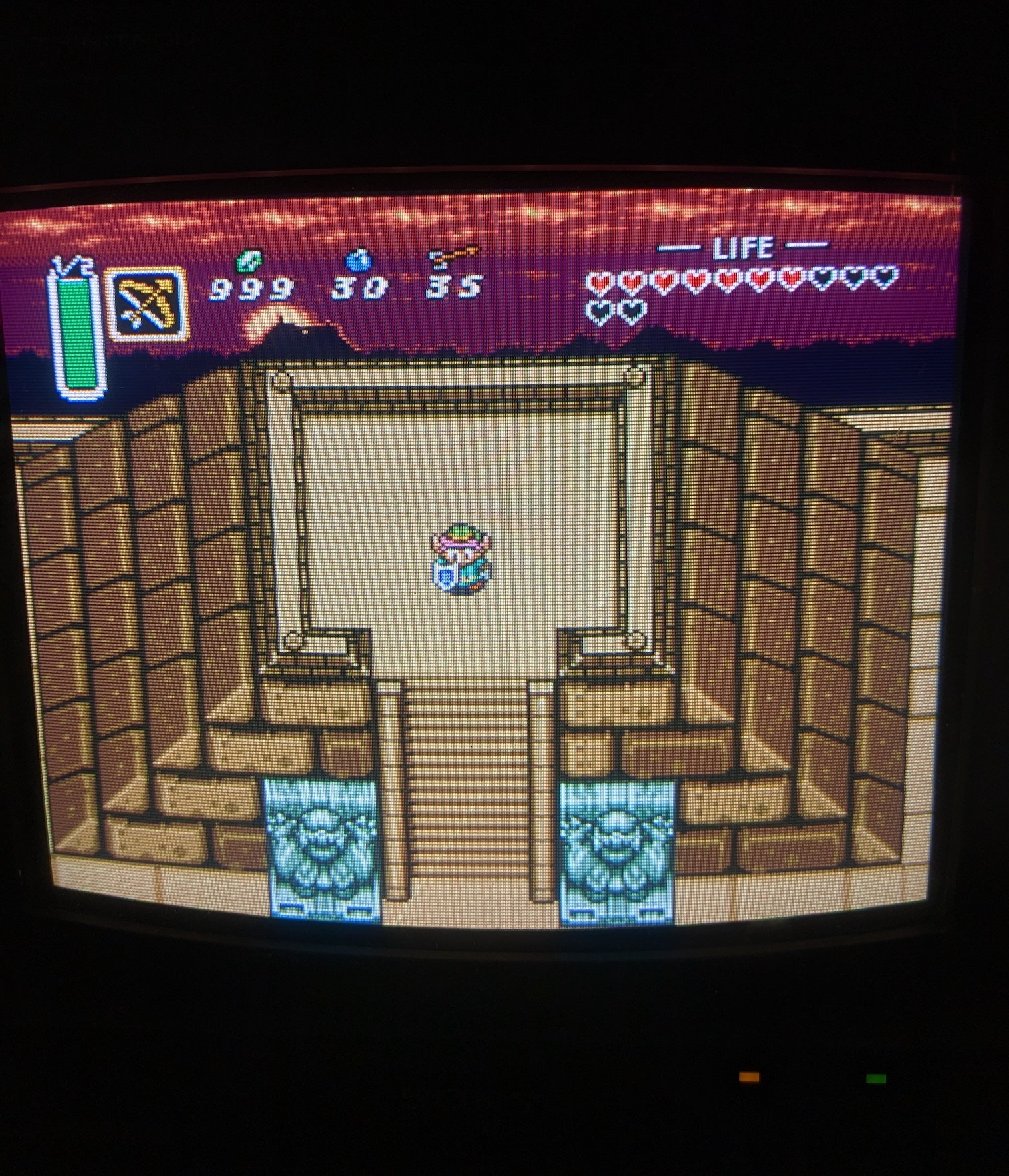
KX-13HG1
1.6B or 1.6A should work as a plug-and-play device. Below pictures show 1.6A, where the cable is pointing upwards.

KV-1311CR
Works as a plug-and-play device. v1.6C custom adapter was specifically designed for the KV-1311CR to enable audio through the external 5V blanking signal. Additionally, to utilize the mono speakers effectively, two 1Kohm resistors were incorporated into both the left and right audio channels on the adapter board.
Please also check out KV-1311CR dedicated article.
Pics from older adapters 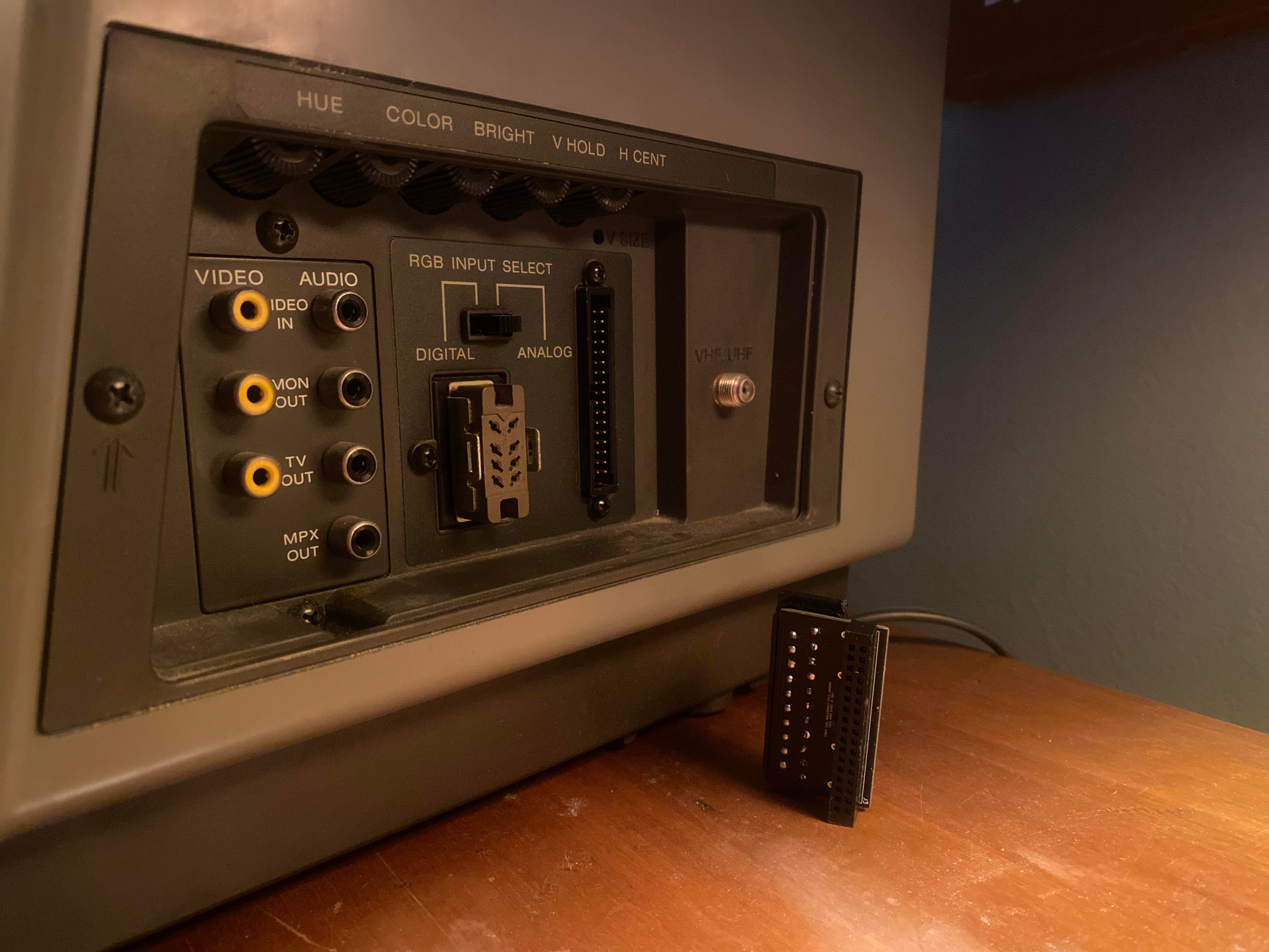
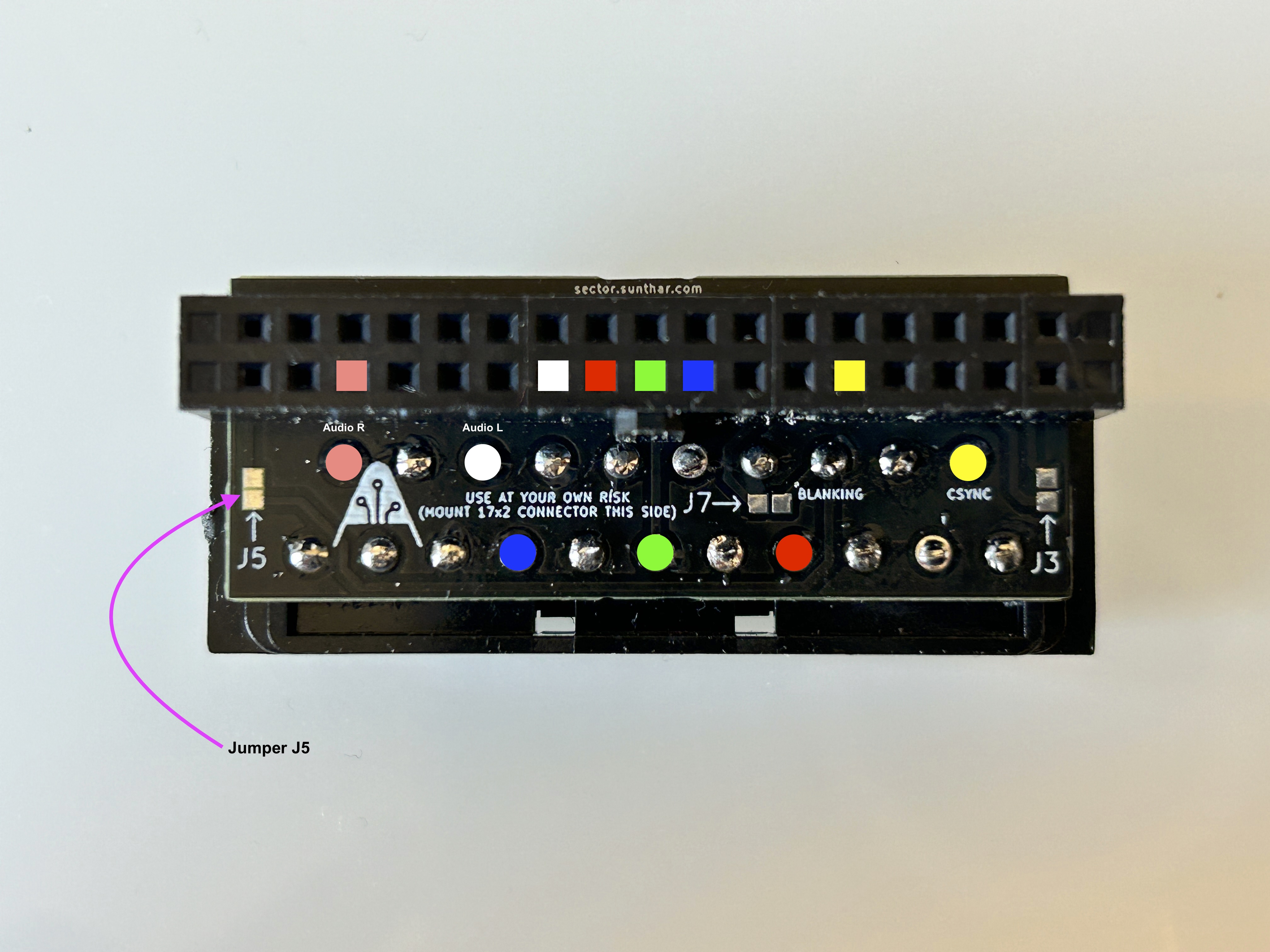
v1.6C board is recommended to keep the cables pointing downwards. Jumper J5 must be soldered for the set to use the audio input from SCART.
NEC CM2591A
New 2cm adapter doesn't need an extension cable. What's shown in the pictures below is the previous version, which required an extension cable. 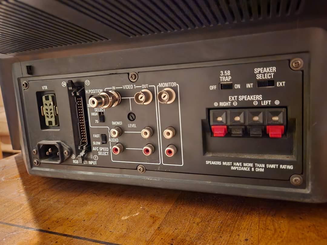

KV-20XBR
Works as plug and play. 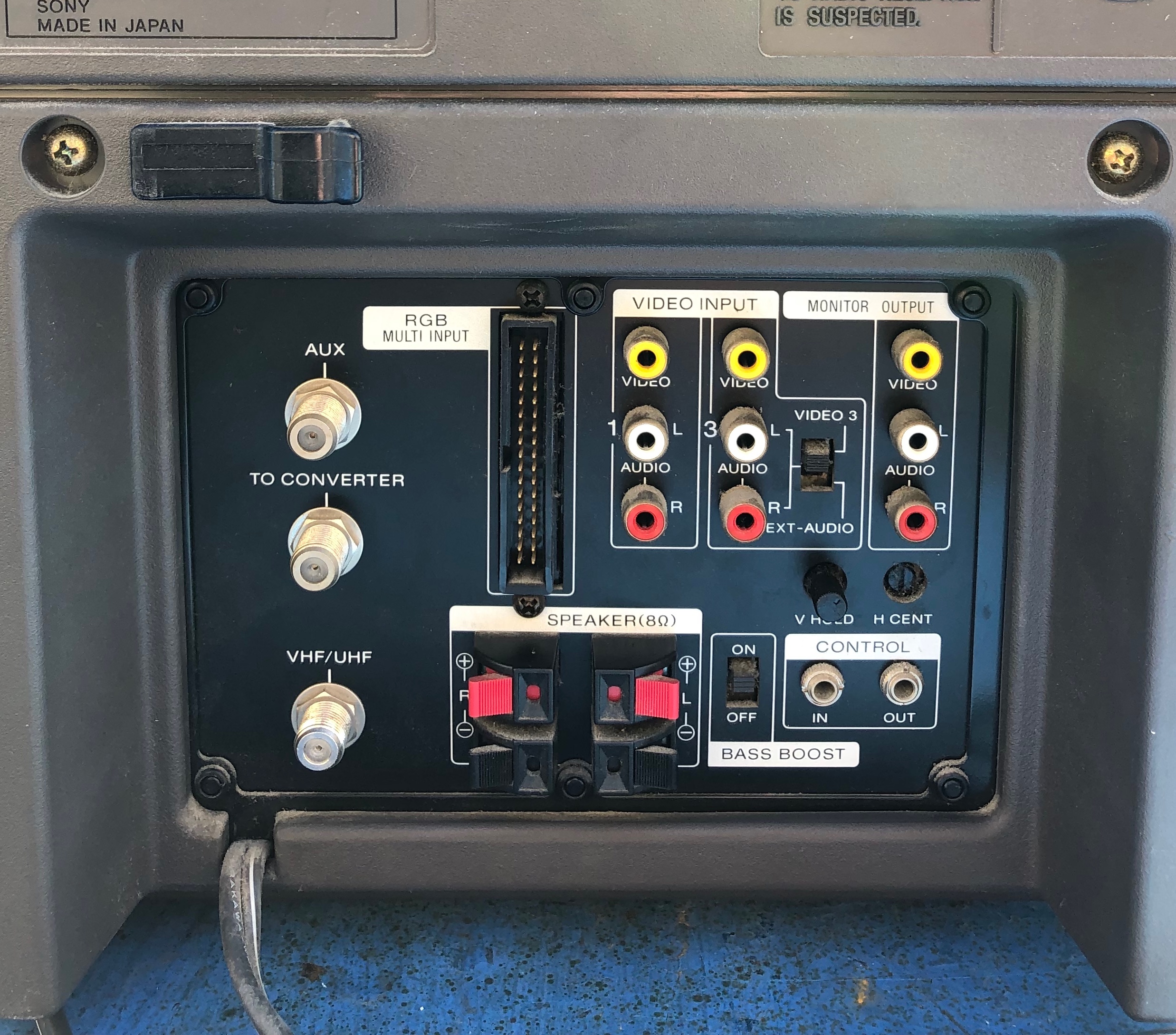
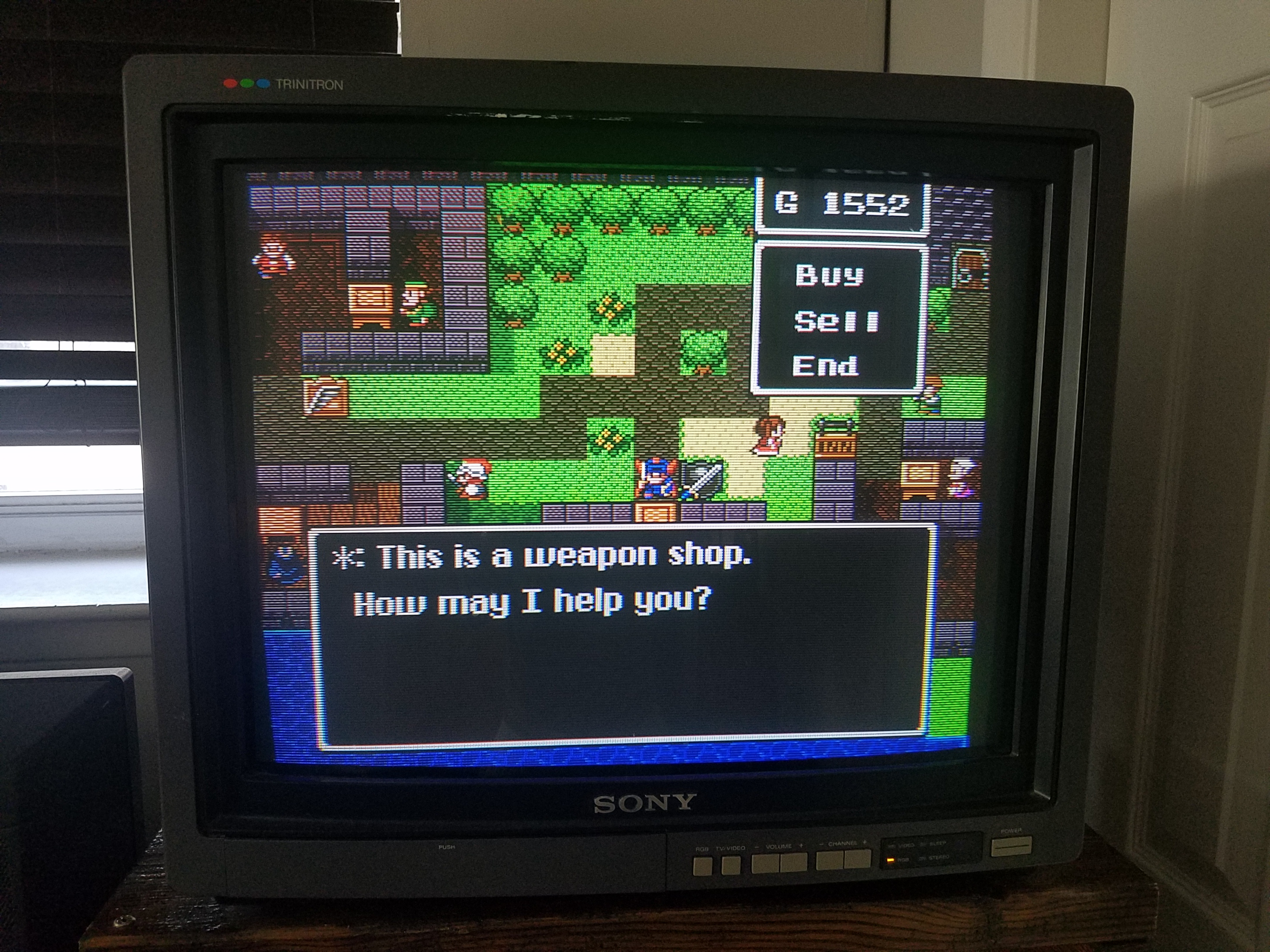
KV-25XBR
Works as plug and play. 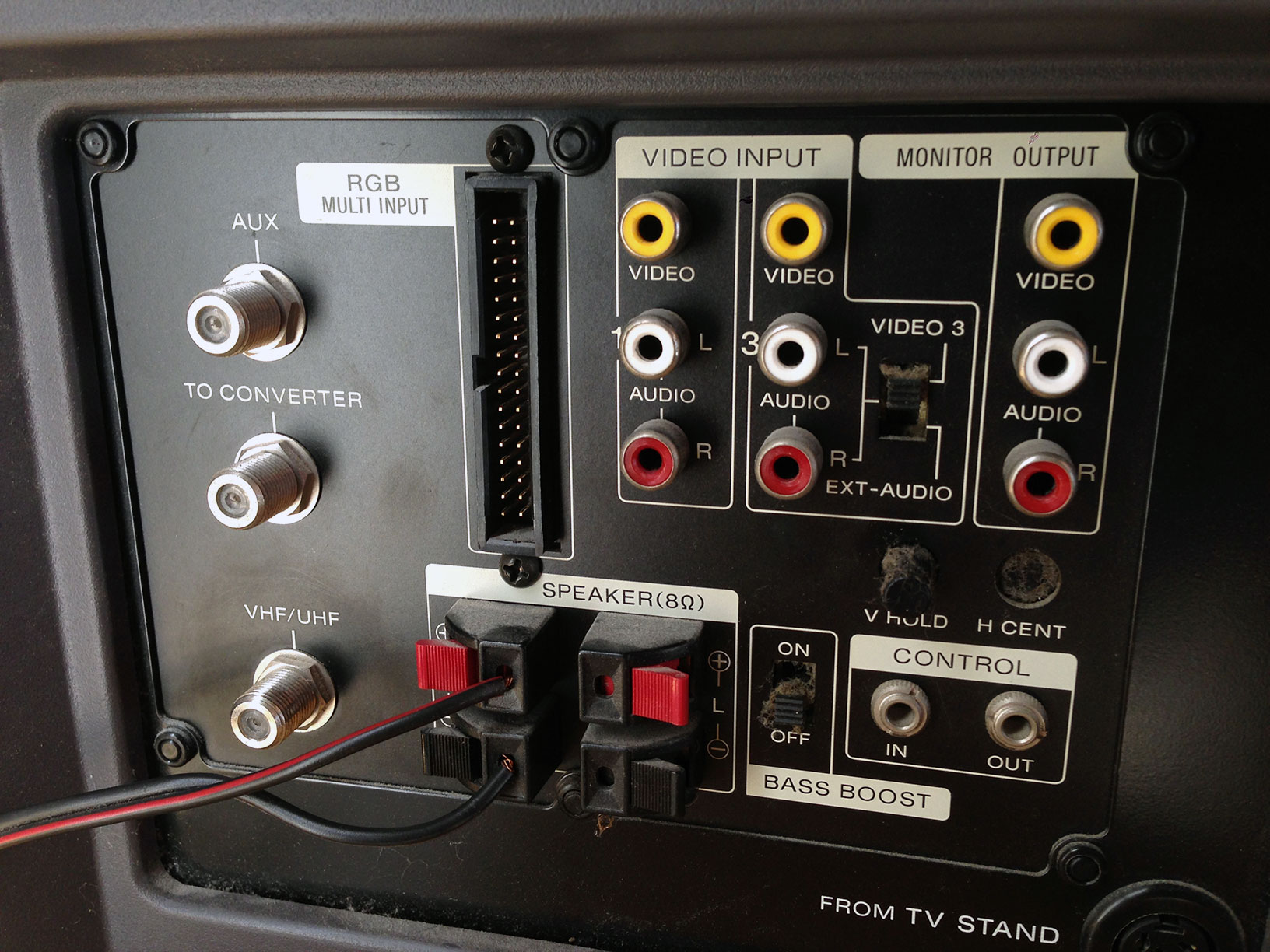
This CRT had some internal issue where there was a red tint. 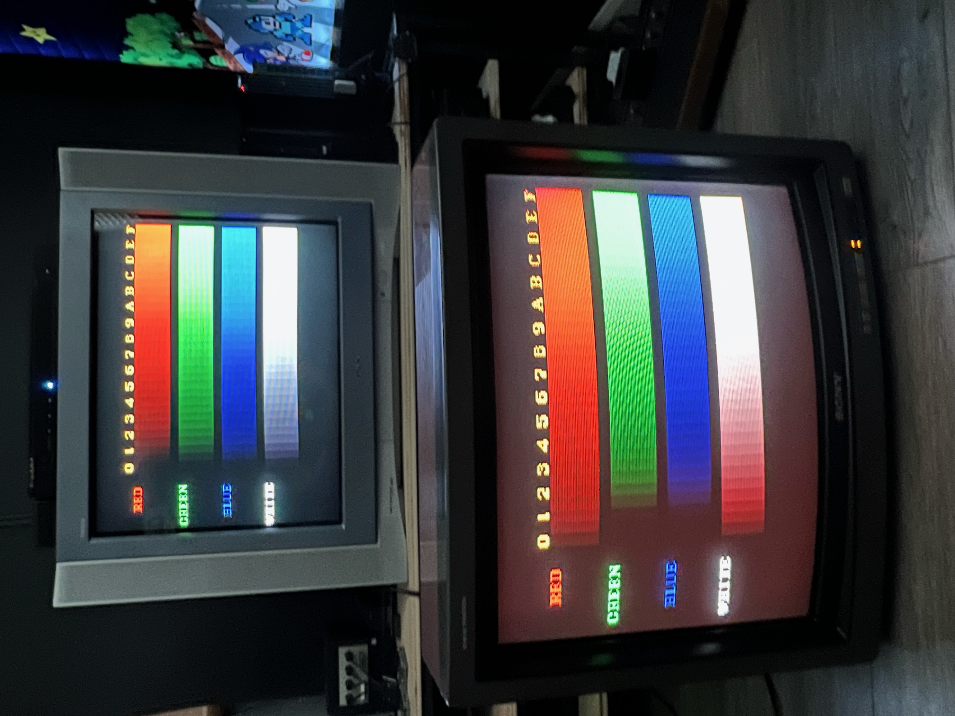
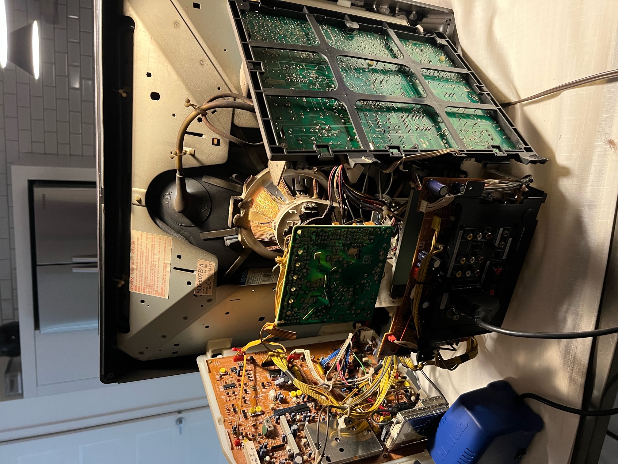
Upon reviewing the schematics, it appears that there is no dedicated potentiometer for external RGB adjustment. However, on the CRT "A" board, there are three capacitors (C824 to C826 - 33uF/16V) located near the RGB connector, and another three capacitors (C401 to C403 - 10uf/16V) that provide the RGB signal to IC401. It may be worth trying to replace the capacitors that are responsible for feeding the red line.
Moreover, there are several pots that you can adjust on the A board, namely RV401 (G SUB BRT), RV402 (B SUB BRT), and RV403 (RGB SUB BRT), which can help fine-tune the RGB signal.
Here are a few suggestions to try:
- Adjust the RV403 pot to see if you can alter the brightness level of the RGB signal without affecting the composite signal.
- Experiment with RV402 and R401; increasing the G and B values should reduce the red tint.
- Check the capacitor on the red path and replace them if necessary.
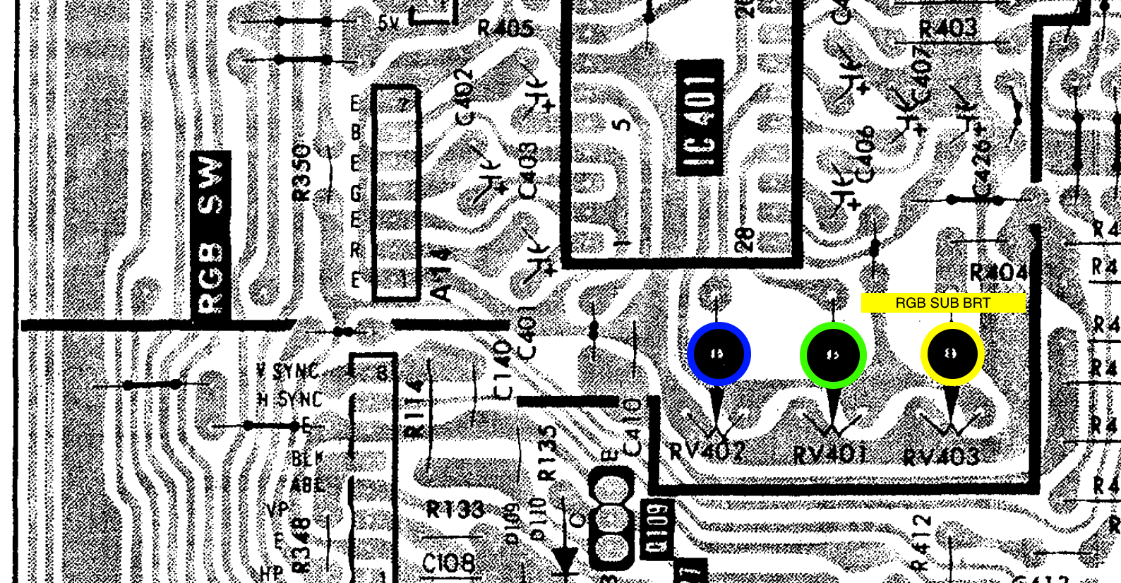
Lowering (RV403) RGB SUB BRT and increasing the RV401 (G SUB BRT), RV402 (B SUB BRT) ever so slightly and the RGB colors on this CRT is FIXED!!!
After adjusting 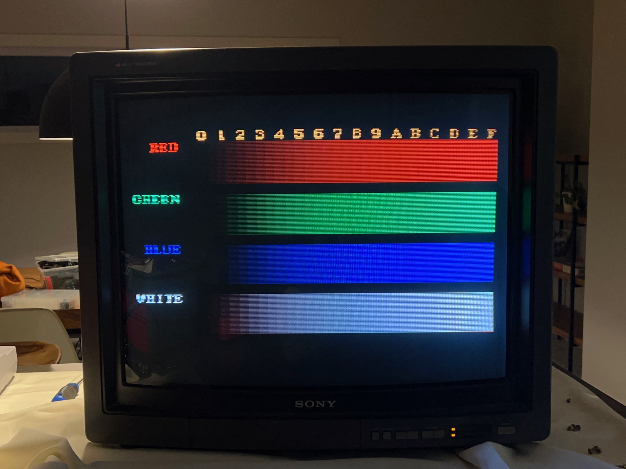
KV-25DXR
Should work as plug and play, if you remove the ground screw. Please make sure to insulate the back of the adapter. 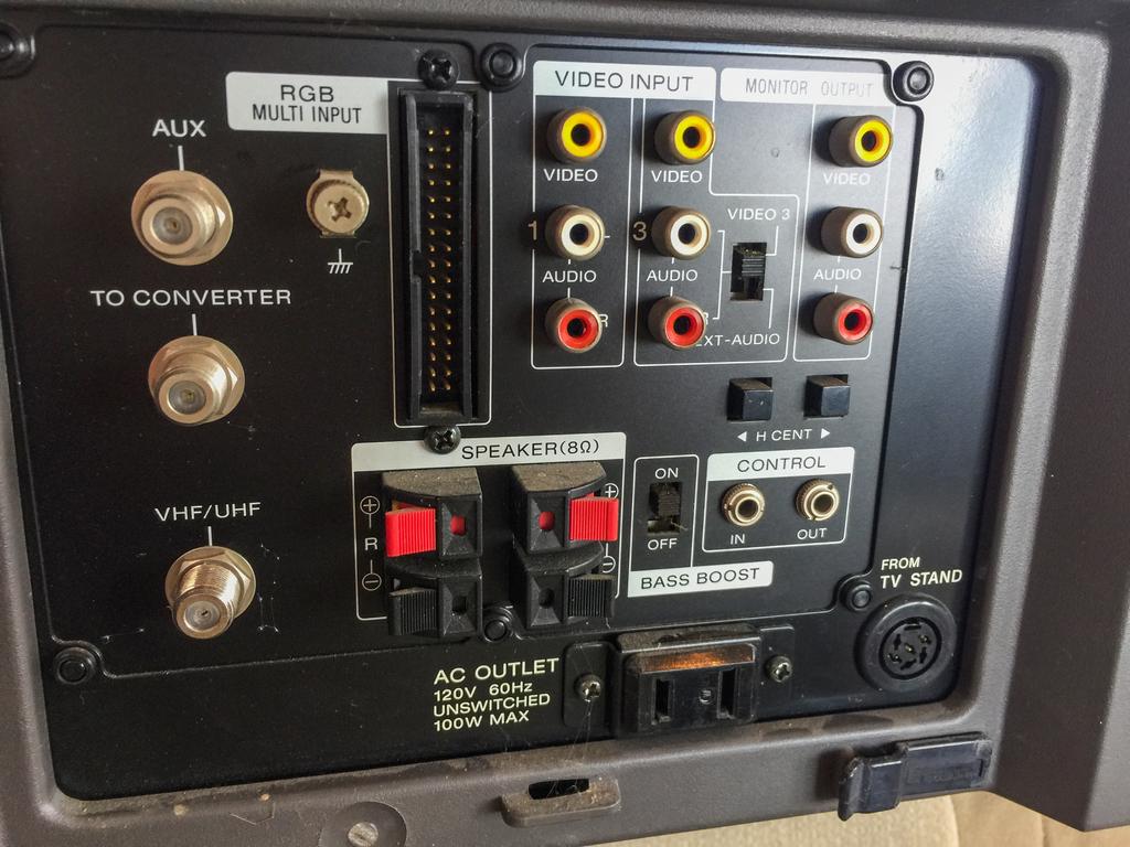
Another option is to use a small 34pin extension cable. 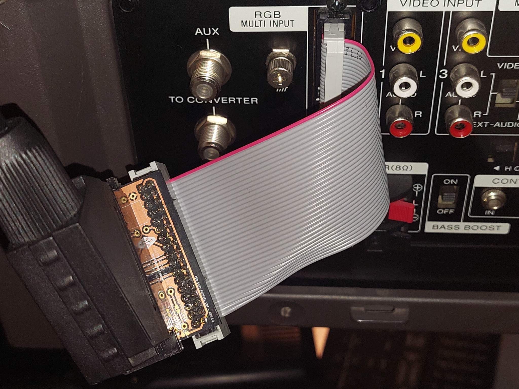
KX-27PS1/KX-20PS1
Note: These sets use digital RGB for teletext and therefore are not compatible with my boards.
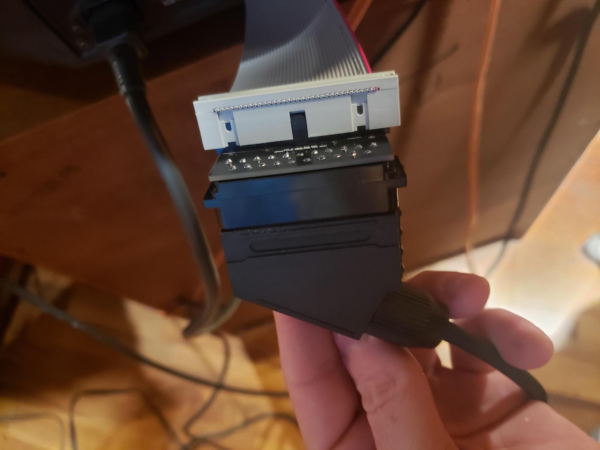
Early prototype
I guess you have to start somewhere with these mods. This was my early prototype made with a floppy cable. While it worked, it was really messy.
Someone made this adapter. It's nice to see how they made their's as well. Click the image below to see the imgur post.
34 pin connector
Mapping for the 34 pin connector to the floppy connector can be seen below.
Pin Translation
| TV PIN | Floppy PIN | TV PIN | Floppy PIN | ||||
|---|---|---|---|---|---|---|---|
| 5V | 1 | 34 | < | NC | 18 | 33 | |
| 5V | 2 | 32 | NC | 19 | 31 | ||
| Audio (R) Ground | 3 | 30 | < | Audio (R) Input | 20 | 29 | |
| Ground | 4 | 28 | Mode Select | 21 | 27 | ||
| Remote Ground | 5 | 26 | NC | 22 | 25 | ||
| Composite Ground | 6 | 24 | < | Composite Output | 23 | 23 | |
| Audio (L) Ground | 7 | 22 | < | Audio (L) Input | 24 | 21 | < |
| Red Ground | 8 | 20 | < | Red Input | 25 | 19 | < |
| Green Ground | 9 | 18 | < | Green Input | 26 | 17 | < |
| Blue Ground | 10 | 16 | < | Blue Input | 27 | 15 | < |
| Ground | 11 | 14 | NC | 28 | 13 | ||
| Ground | 12 | 12 | Blanking Input (3V) | 29 | 11 | < | |
| Ground | 13 | 10 | < | Composite Sync Input | 30 | 9 | < |
| NC | 14 | 8 | NC | 31 | 7 | ||
| Ground | 15 | 6 | NC | 32 | 5 | ||
| Ground | 16 | 4 | RGB Mode Select | 33 | 3 | ||
| NC | 17 | 2 | Audio Select | 34 | 1 | < |