JVC AV-36D201
JVC AV-36D201 CRT RGB mod
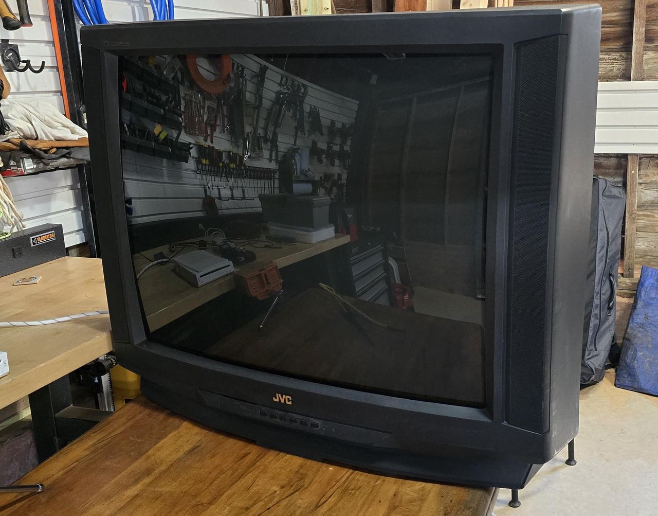
The JVC AV-36D201 is a highly regarded 36" CRT television from the late "D-Series" era, praised for its excellent picture quality, 800-line horizontal resolution, and, for its time, advanced input options. It features a curved tube, component/S-Video inputs, and built-in virtual surround sound.
A great candidate for RGB modding.
View full CRT details and more mod examples →
This tutorial should also work for the following models.
- JVC AV-27D201
- JVC AV-32D201
Contributors
Thank you to everyone who contributed to this guide:
- Snivy102 — contributor, CRT specs from CRT Database.
- Tpoundx — author, RGB mod and pictures
CRT safety
Caution
You can die doing this! So read carefully! CRT TV is not a toy. Do not open a CRT TV. If you don't have any prior knowledge about handling high voltage devices, this guide is not for you. CRT TV contains high enough voltage (20,000+ V) and current to be deadly, even when it is turned off.
Plan of attack
Manuals and Datasheets
Specs
- Year: 2000
- Format: NTSC
- Chassis: GR2
- Jungle Chip: JVC JCC1007A
- OSD Chip: MN1876478JD
- Screen Size: 36"
- Inputs: Composite, S-Video, RF, Component YPbPr
RGB mux diagram
Performing the mod
Now that you roughly know what needs to be done, prepare for the mod. Place the board on a comfortable place. Make sure you are not putting pressure on the flyback or other components.
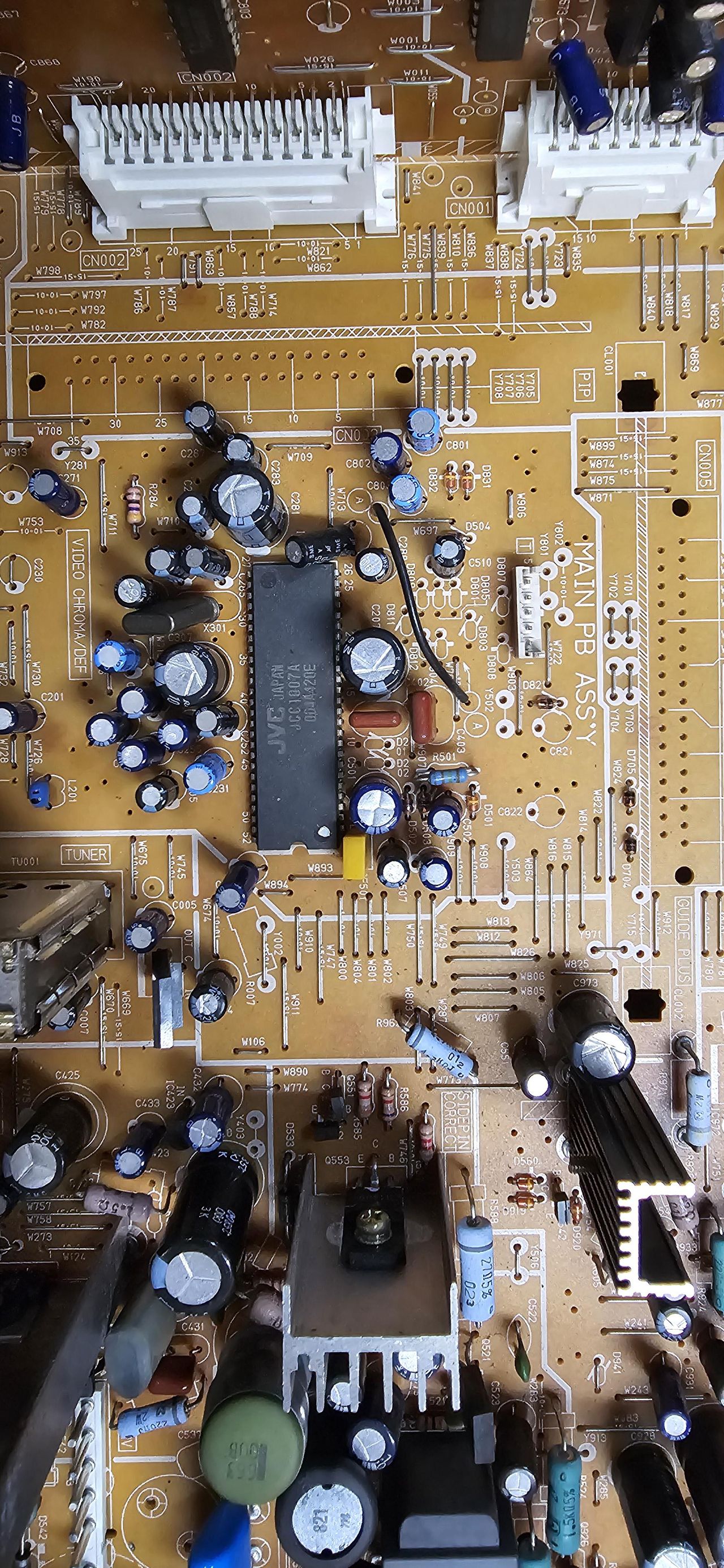
STEP 1: Add caps and diodes
- Replace C801, C802, C803 electrolytic capacitors on chassis with 0.1uF ceramic capacitors.
- Replace jumpers Y706, Y707, Y708 with diodes. Pay attention to the direction of the diodes.
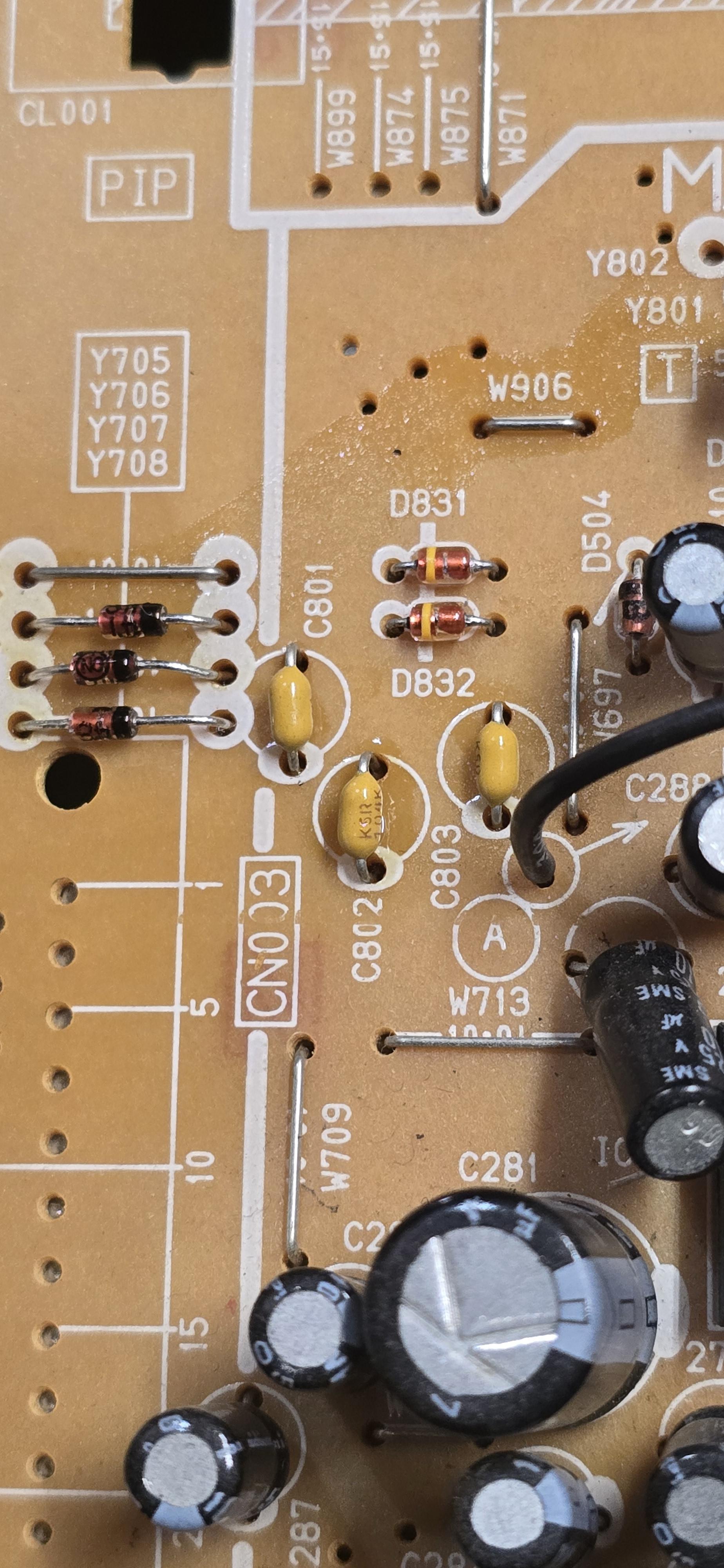
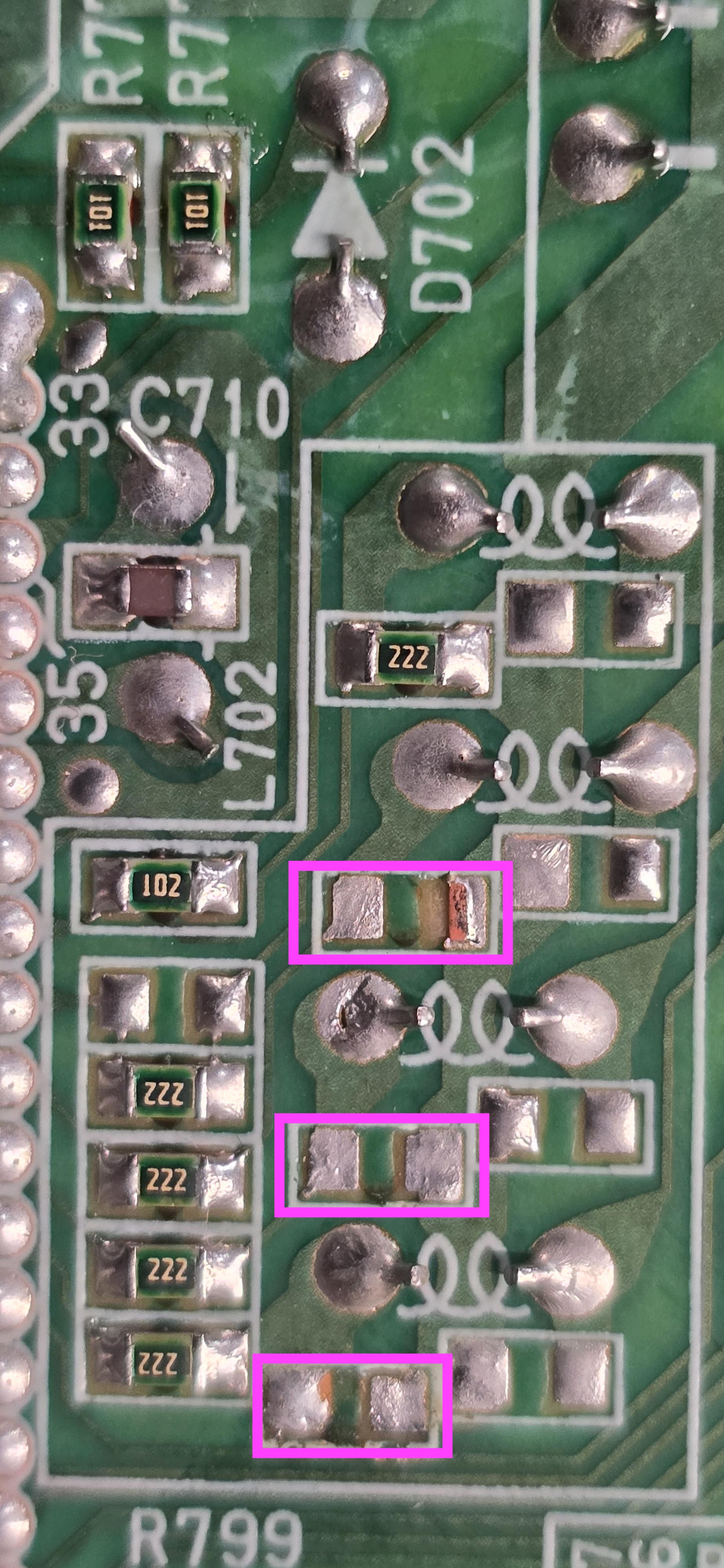
STEP 2: Remove and replace the following components
There are two areas to focus for STEP 2 and 3 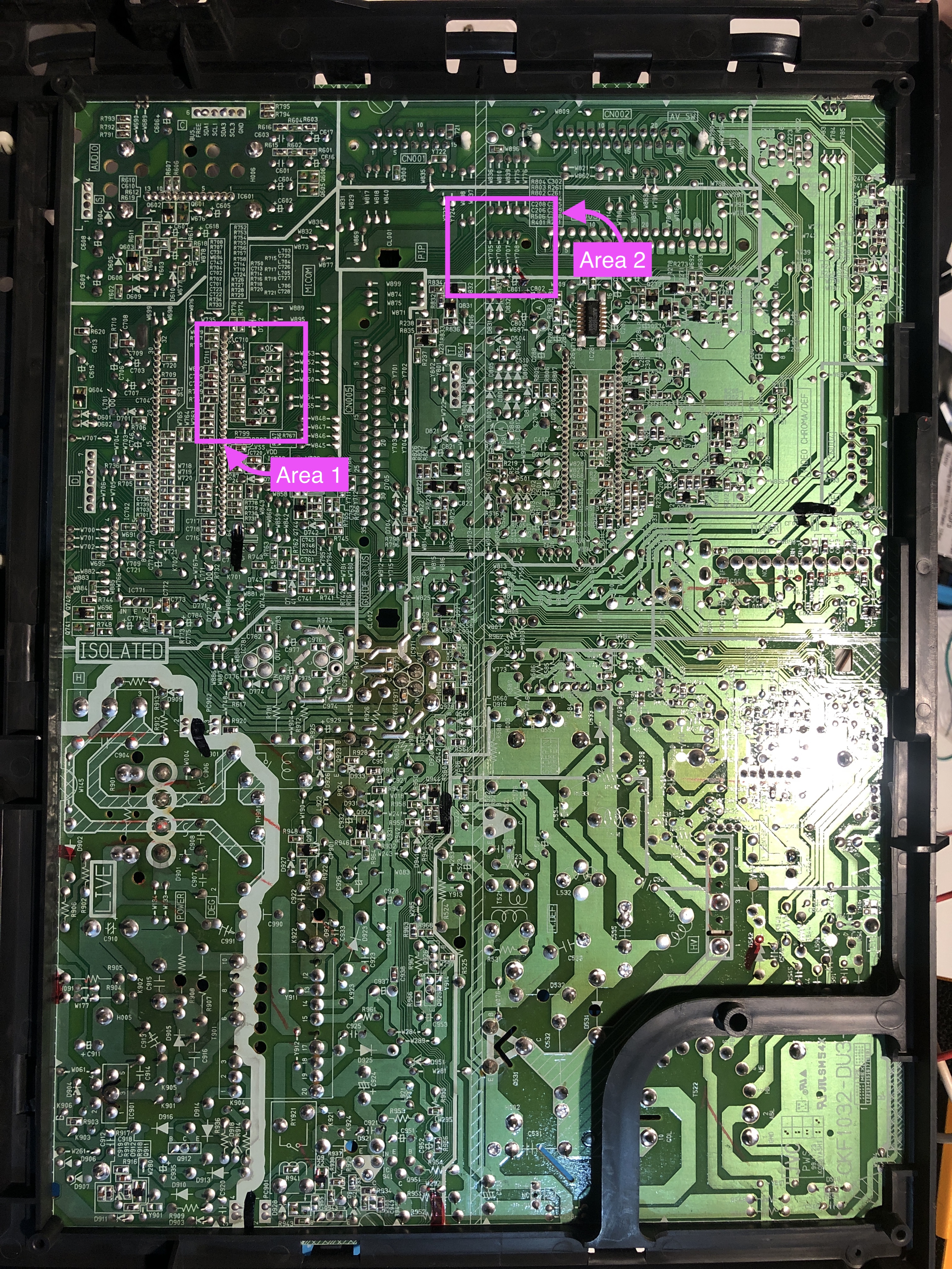
First focus on Area 1 and remove the following three SMD resistors.
- R717 (330 ohms)
- R719 (330 ohms)
- R721 (330 ohms)
STEP 3: Connect RGB, Blanking wires
Next, focus on Area 2 and attach the blanking wires. There is a conveninet hole nearby to route the wires. Make sure you are soldering the wires to the correct leg.
![]()
STEP 4: Sync and audio wires
Sync goes to the green component jack (Video Input 2). Left and right audio also goes with the Input 2.
Audio 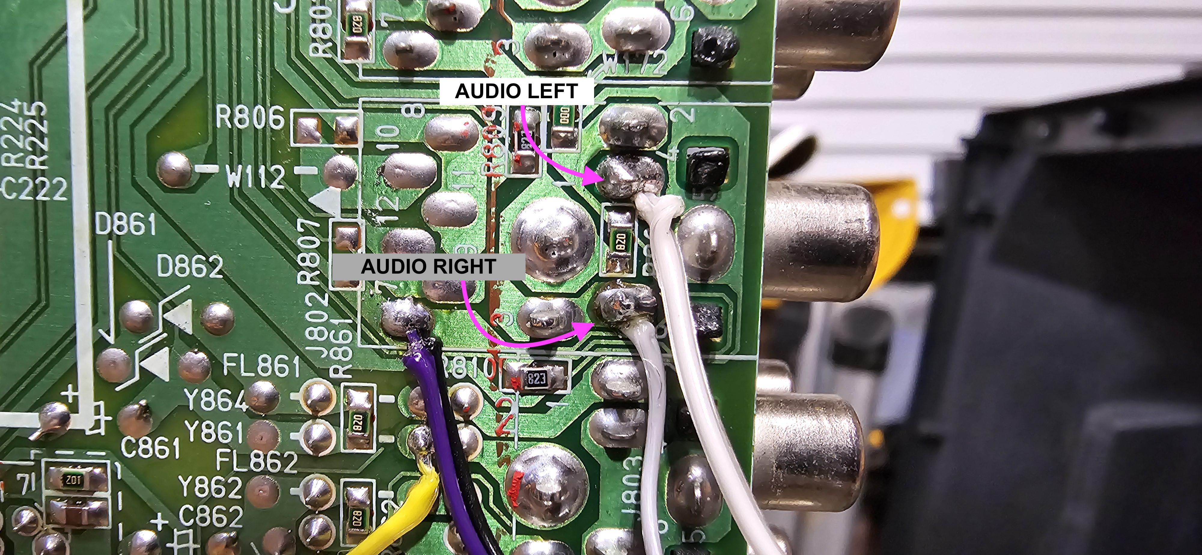
Sync and ground 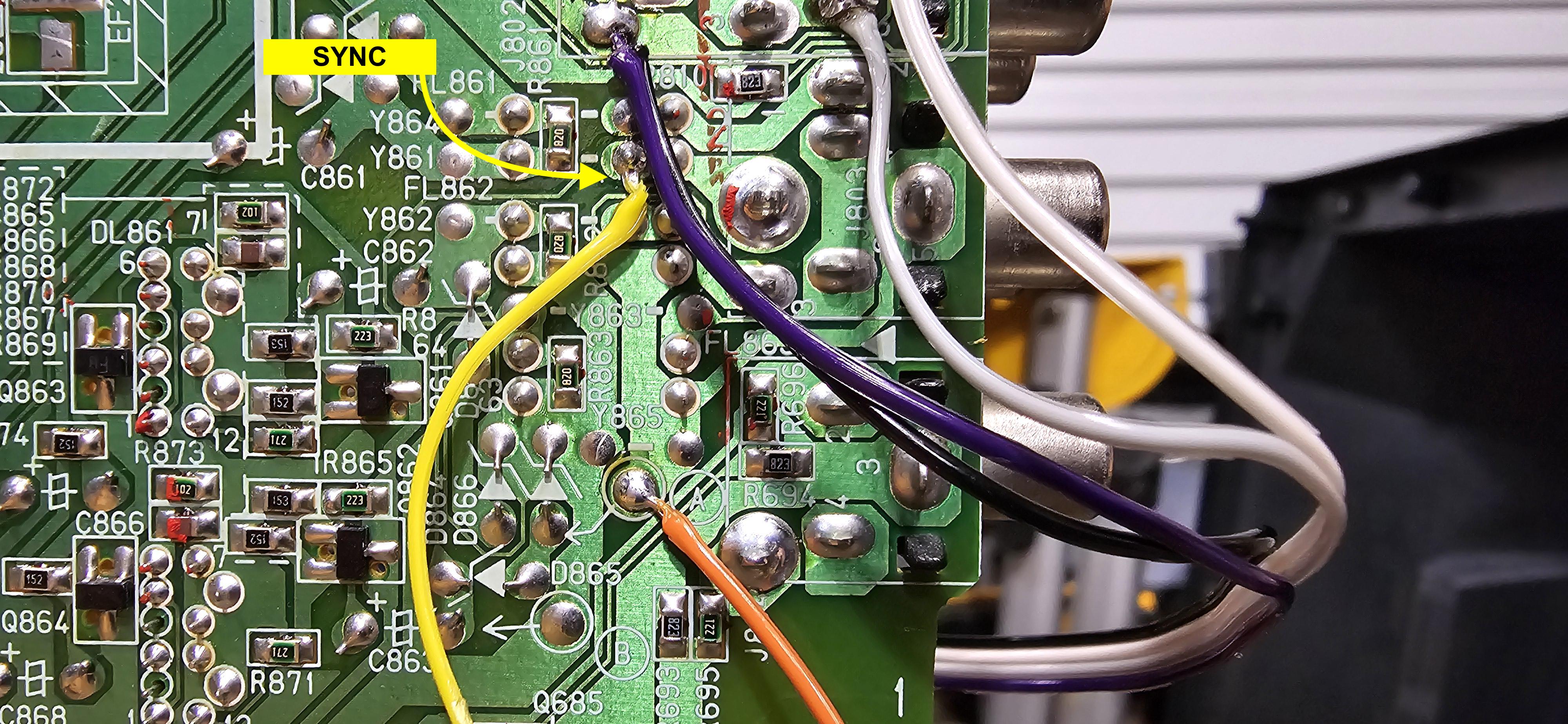
STEP 5: Build your mux board
This mod uses the RGB mux board. This is optional, but will make your mod easier and stable. You can also create the circuit presented in the schematics above without the board. Please also checkout the mux calculator to play with your own values.
| Component | Value |
|---|---|
| RGB/OSD inline resistor (chassis) | 2.2kΩ |
| Removed RGB/OSD resistor (chassis) | 330Ω |
| RGB inline diode method (chassis) | Yes |
| 0.1μF caps replaced (chassis) | Yes |
| RGB termination (R1, R2, R3) | 75Ω |
| RGB inline (R4, R5, R6) | 390Ω |
| Audio LR (R7, R8) | 1kΩ |
| Diode (R9) | 1N4148 |
| Blanking Ground Resistor (R10) | open |
| Blanking Resistor (R11) | 1kΩ |
RGB mux board kit was shipped with few pins soldered. 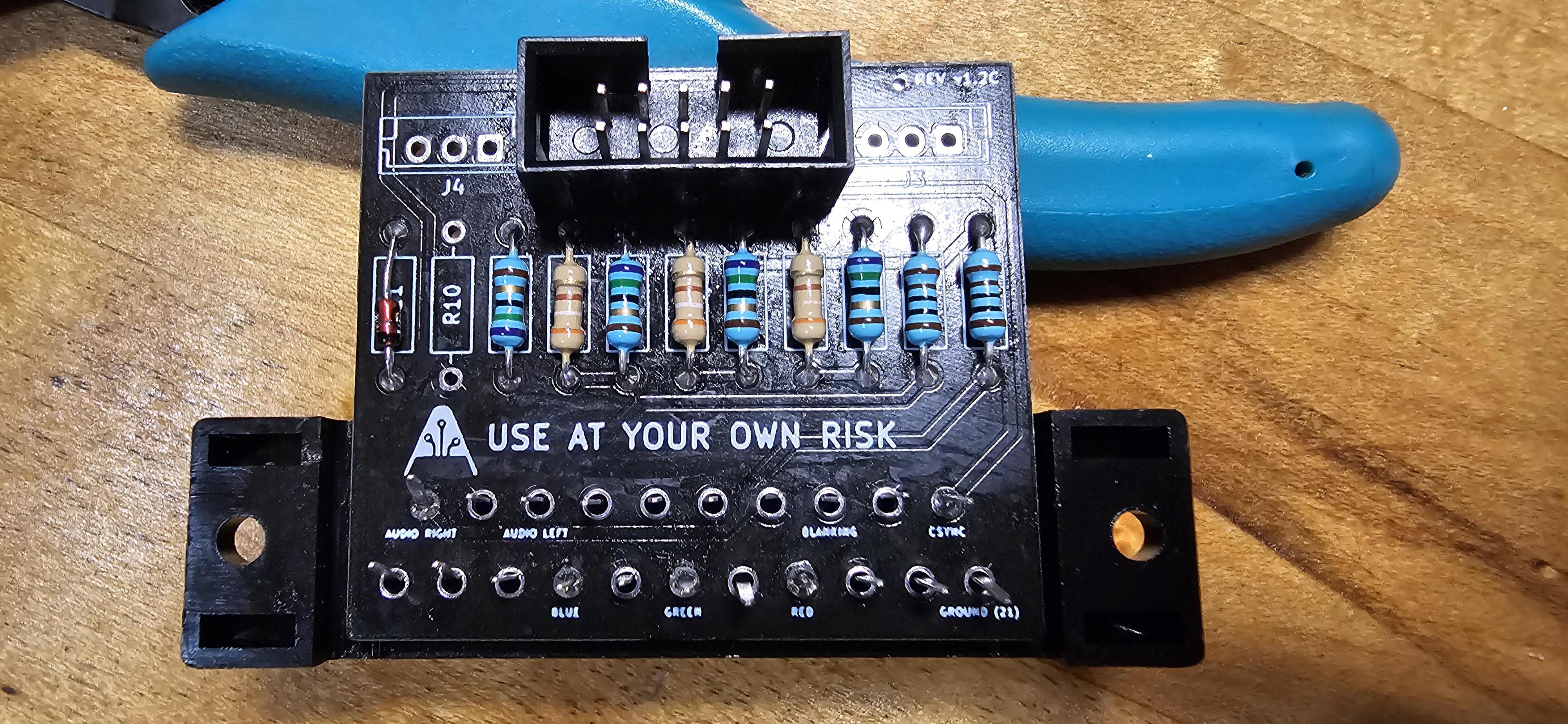
After soldering all the pins on the board. 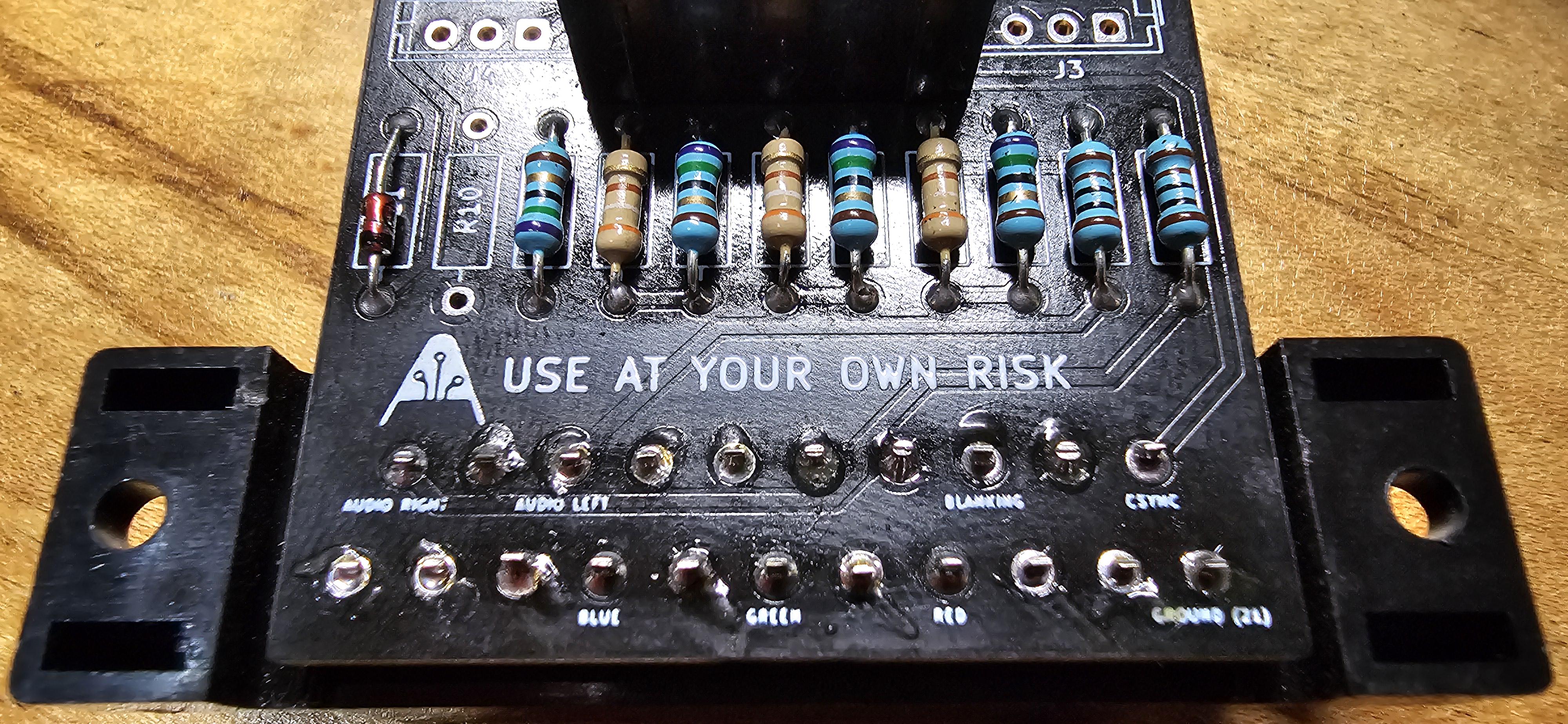
Look at the tight fit in the below pictures.
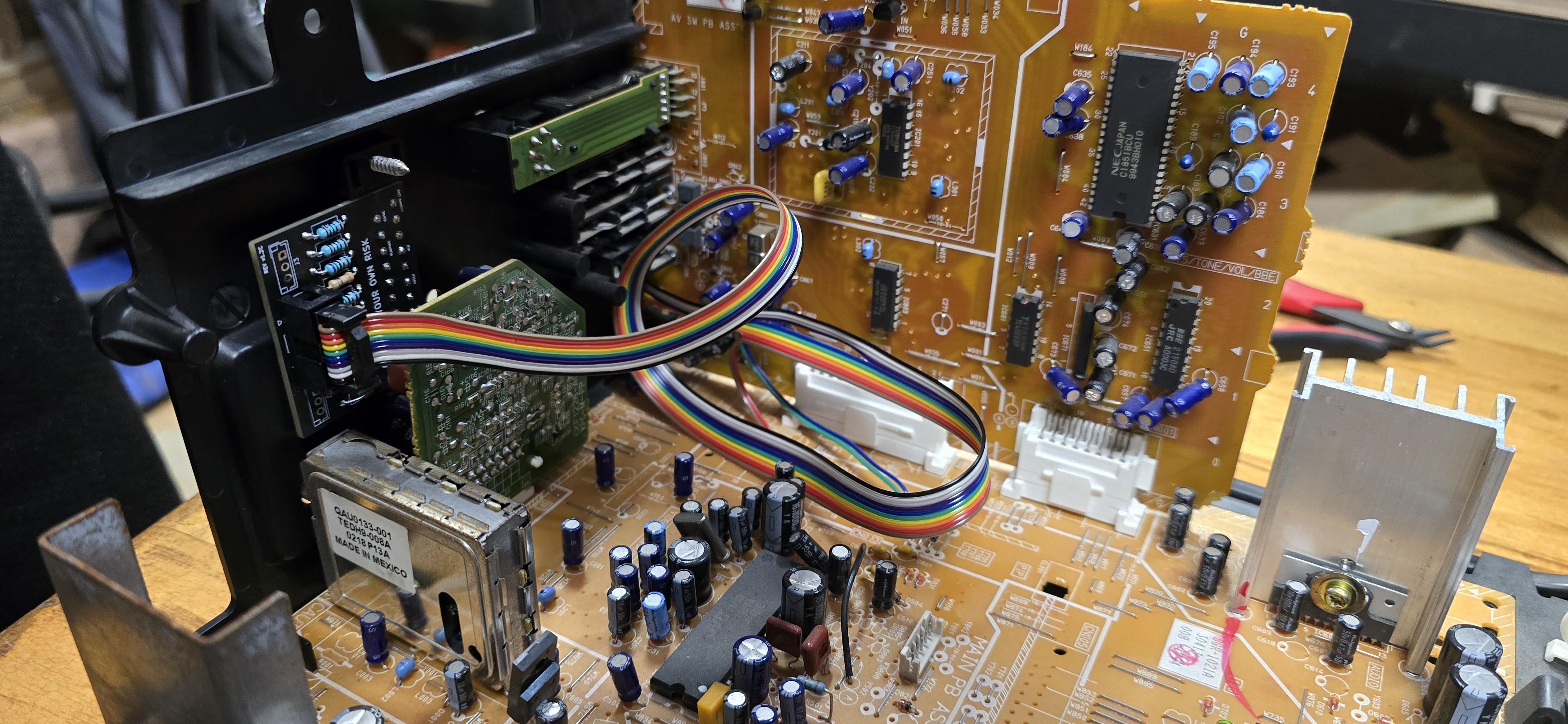
One must carefully plan where the mux board should go.

End result is very satisfying. This is where the SCART port belongs on a 32", D201.
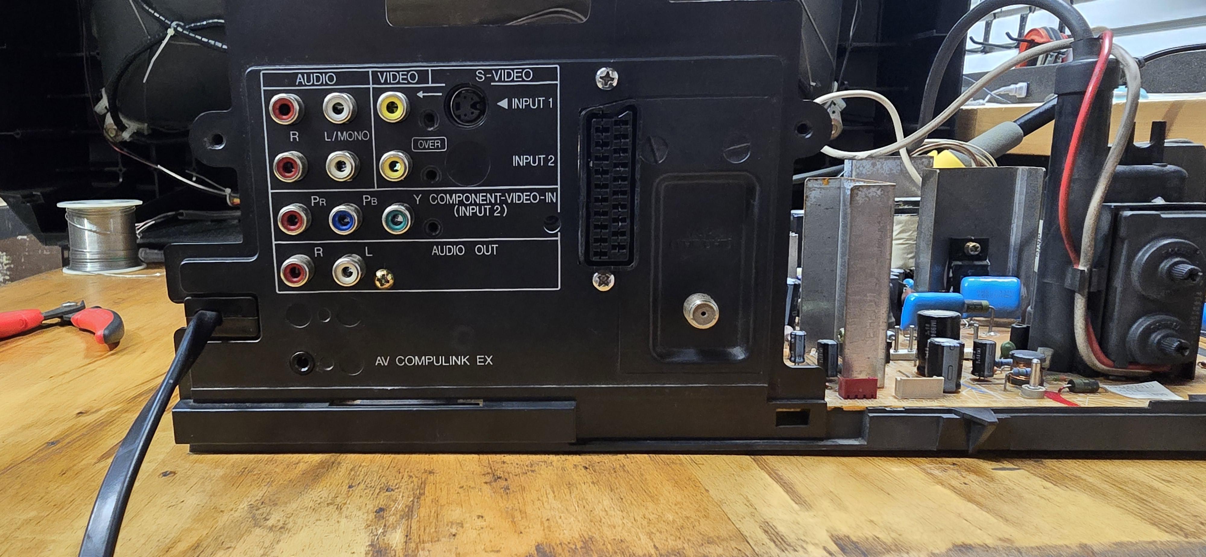
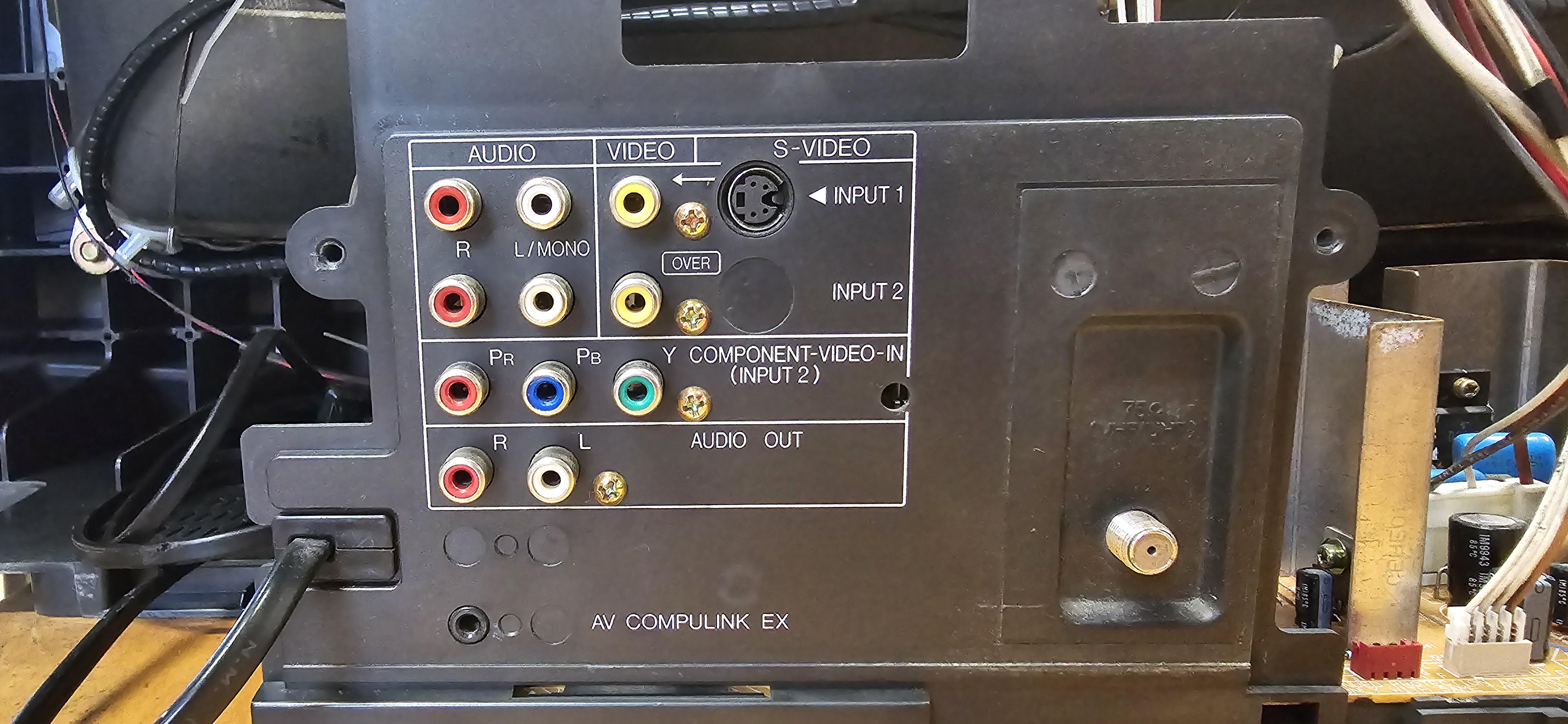
STEP 6: Attach the female SCART connector to TV
Creating a SCART cutout and mounting it is an art. I have a dedicated section for it. How to create and mount a SCART female plug?
Service Menu
- Press the
SLEEP TIMERkey and set theSLEEP TIMERfor0 MIN - While the
SLEEP TIMERis displaying on the CRT, do the below - Immediately press the
DISPLAYkey and theVIDEO STATUSkey of the remote control unit at the same time. - Then enter the
SERVICE MENUscreen shown in figure.
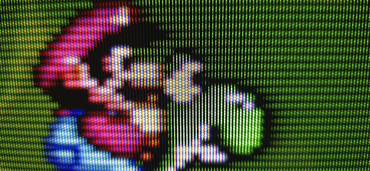
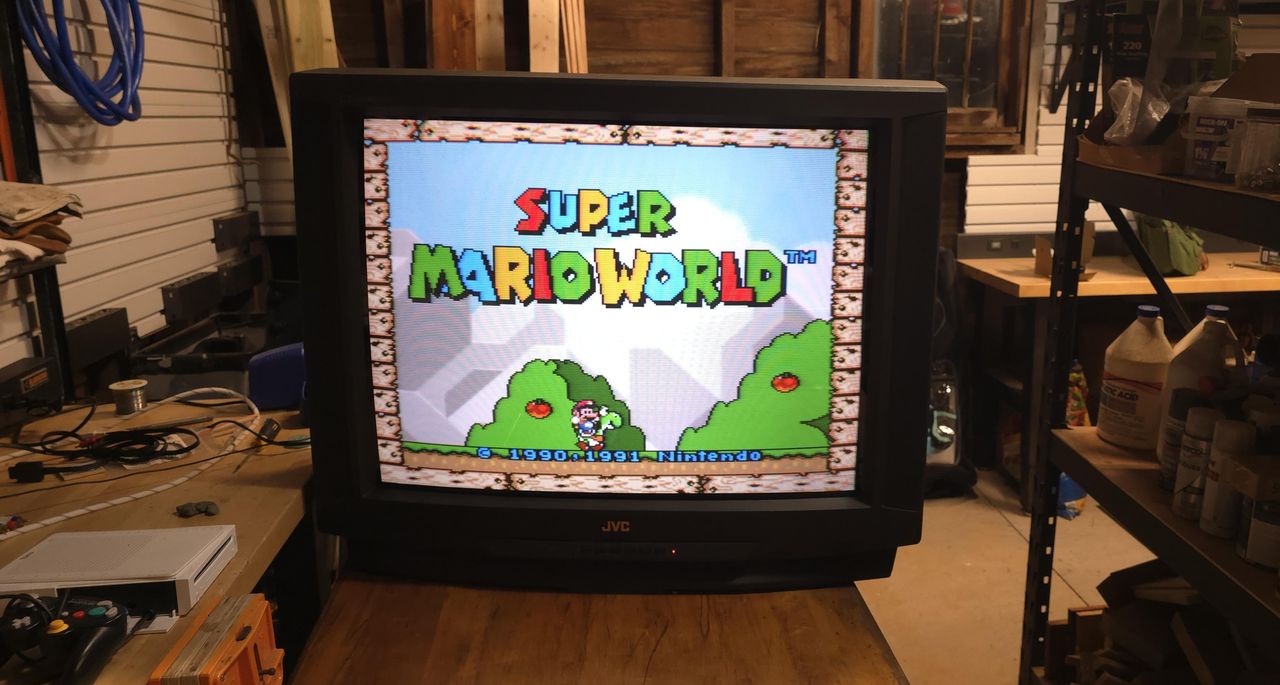
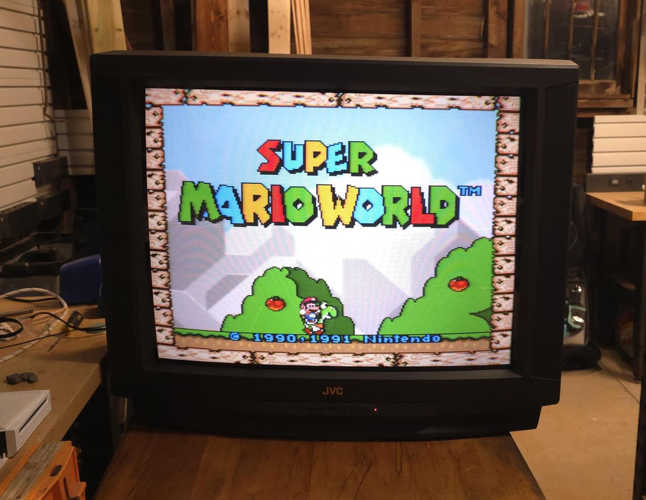
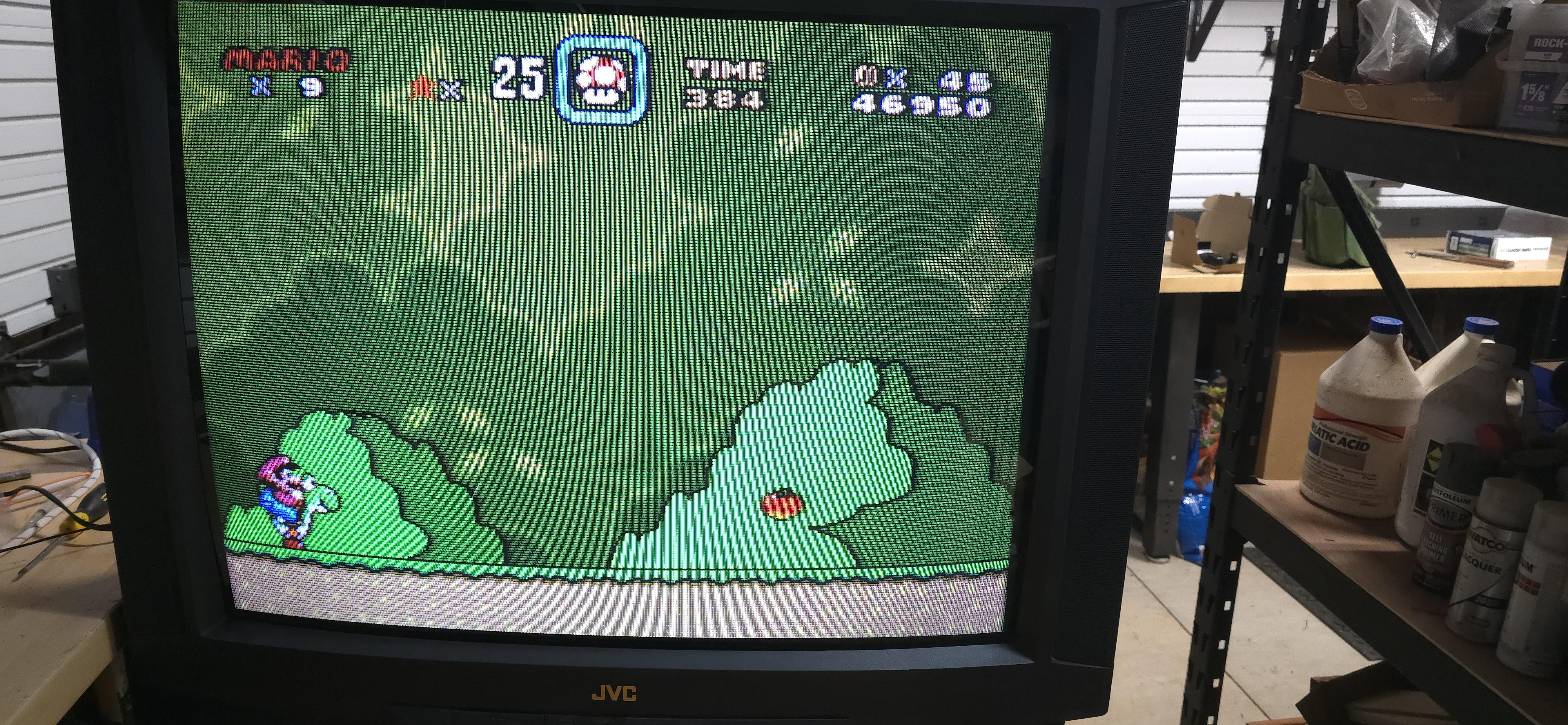
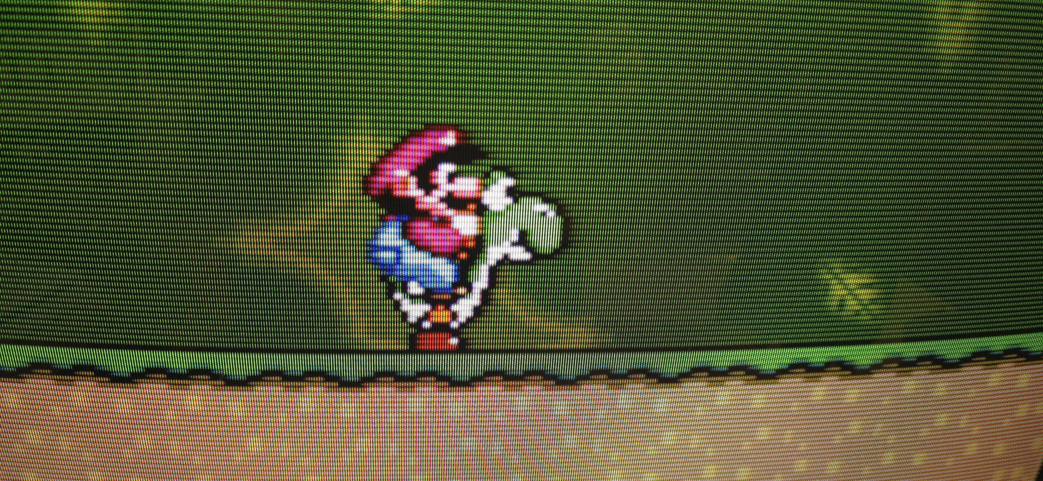
SNES - Super Mario World 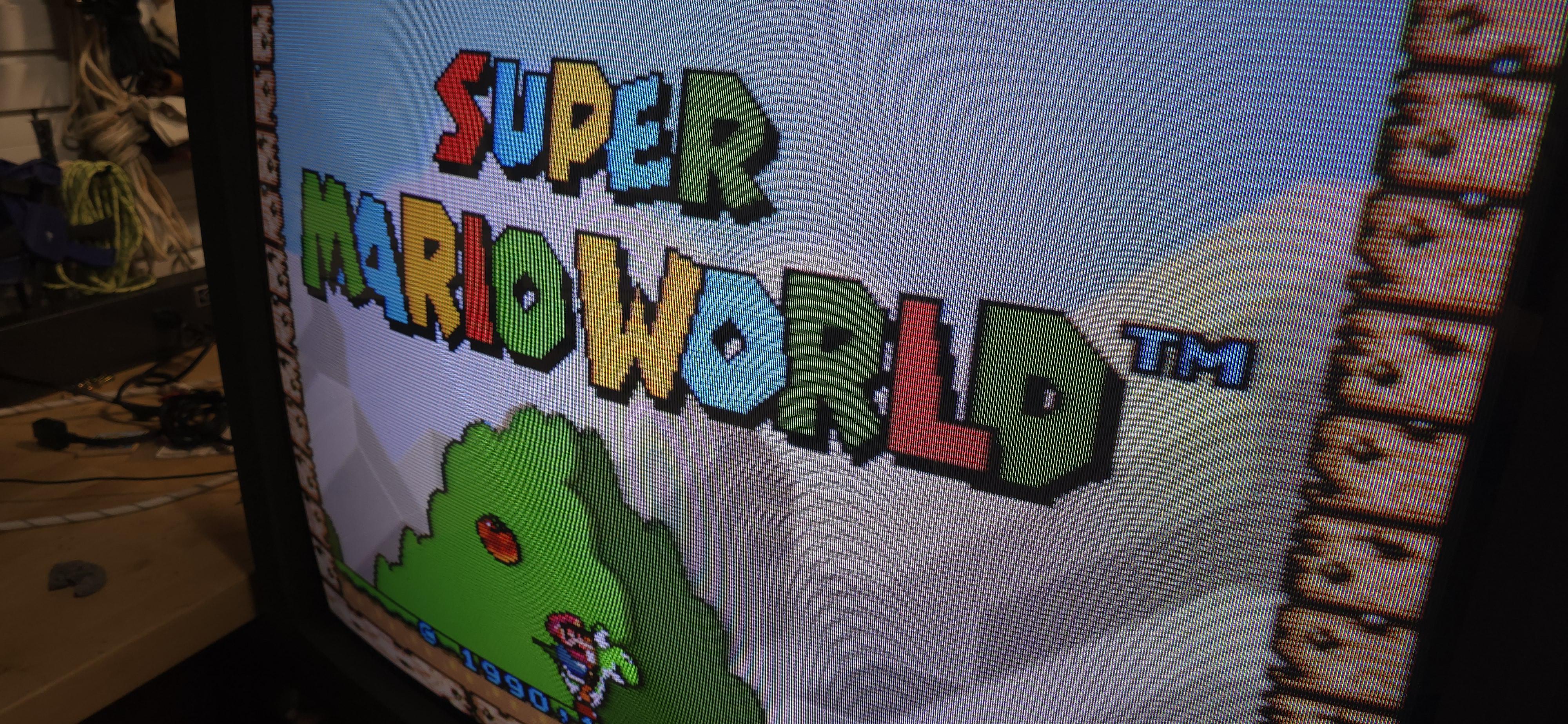
![]()
Set
Before installing the SCART port 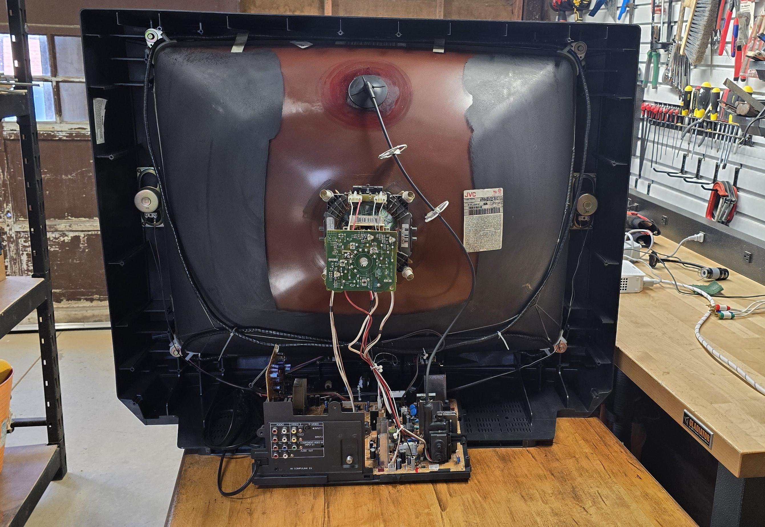
After installing the SCART port 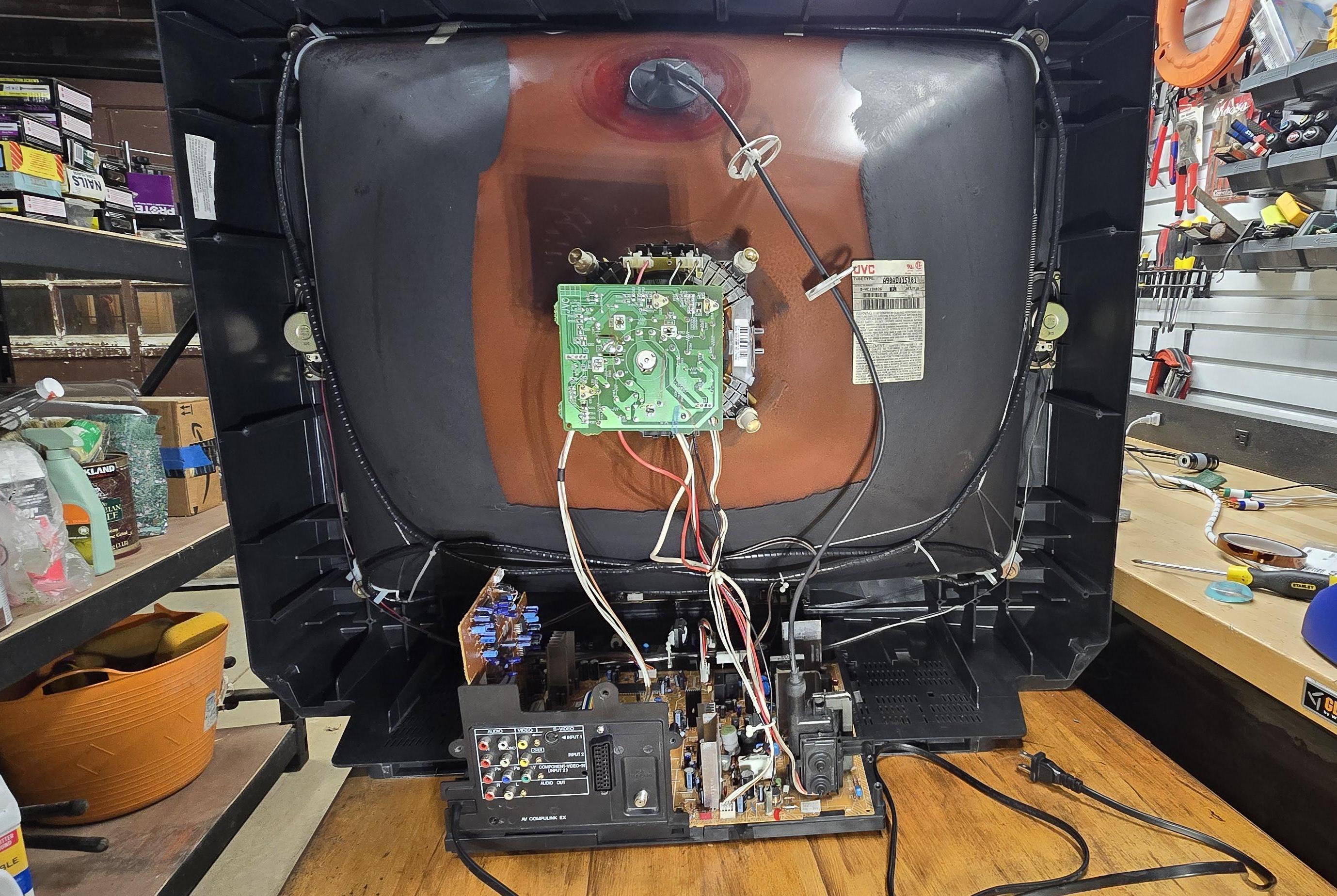
Pictures
Reference Photos