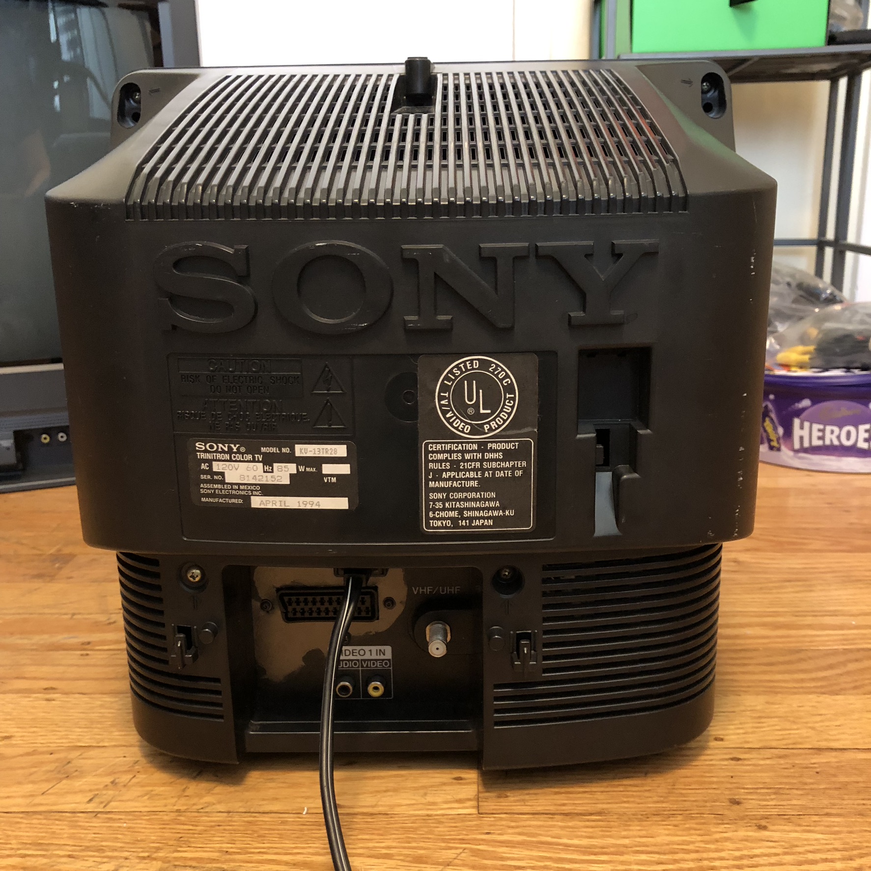
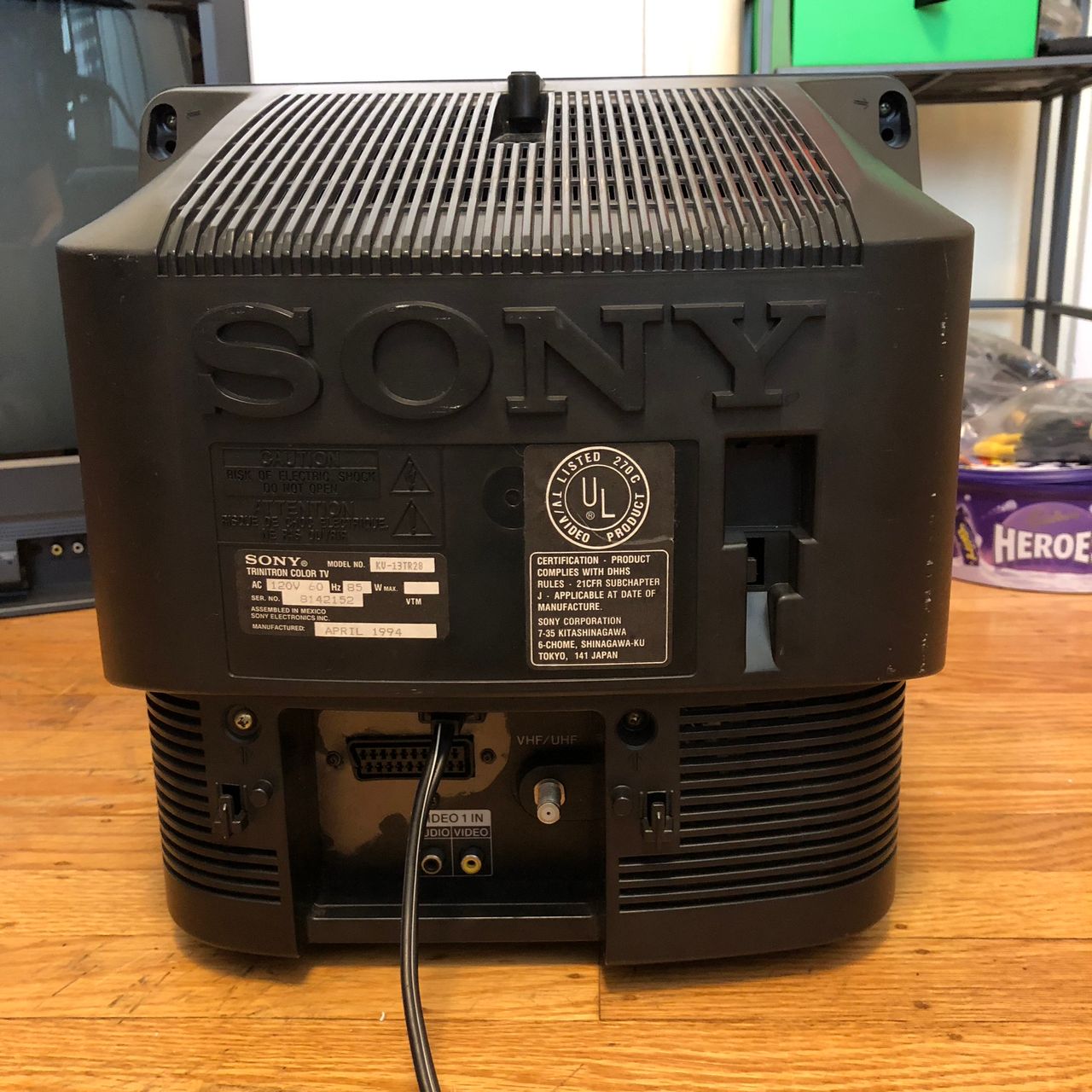
Sony (BA-1) KV-13TR28
Sony KV-13TR28 CRT RGB mod
Below mod was performed on KV-13TR28 by Kaz Packman.
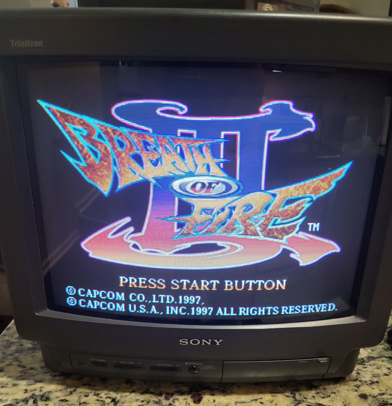
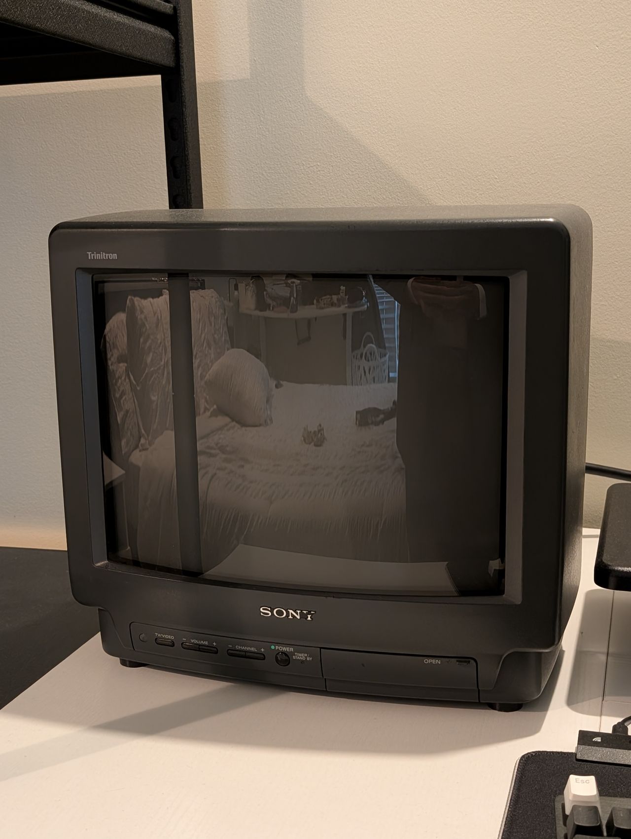
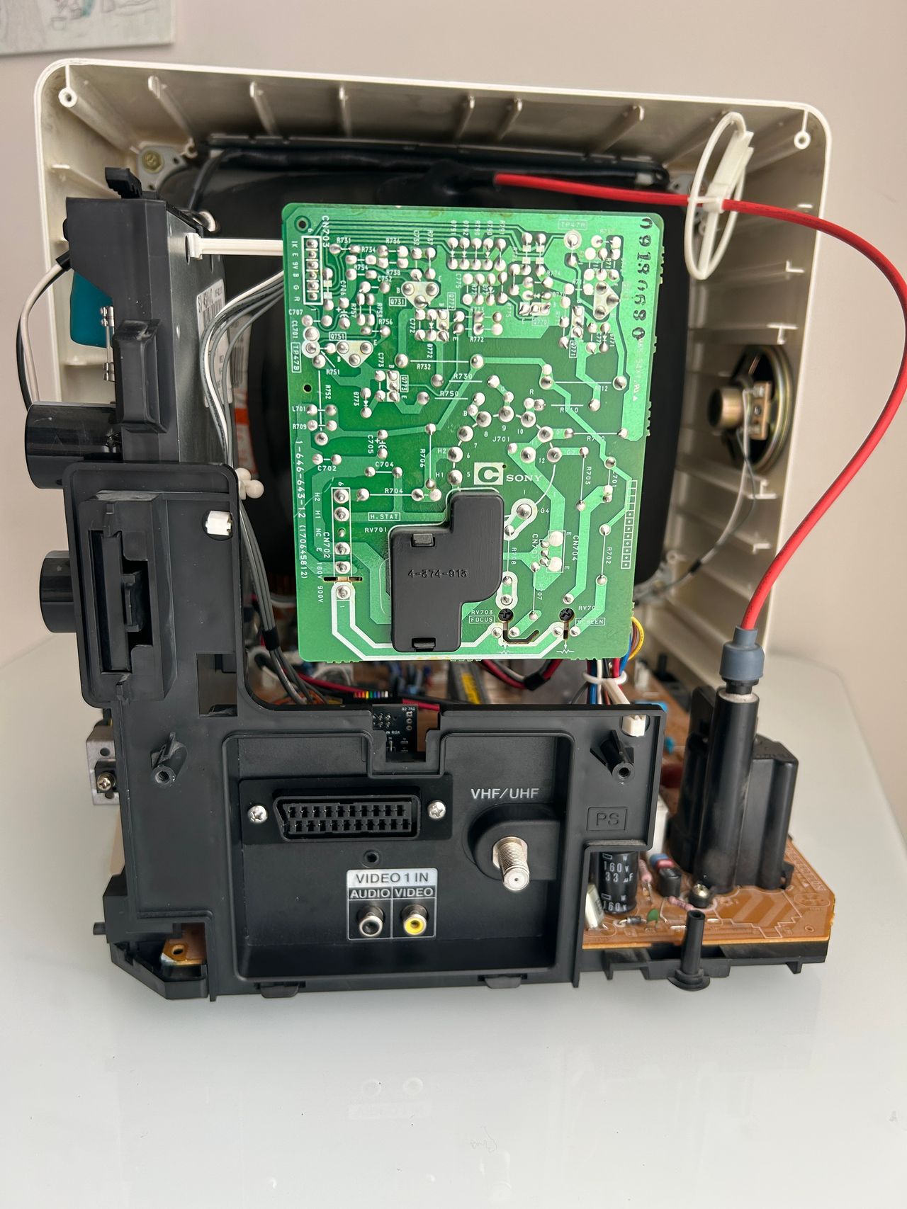
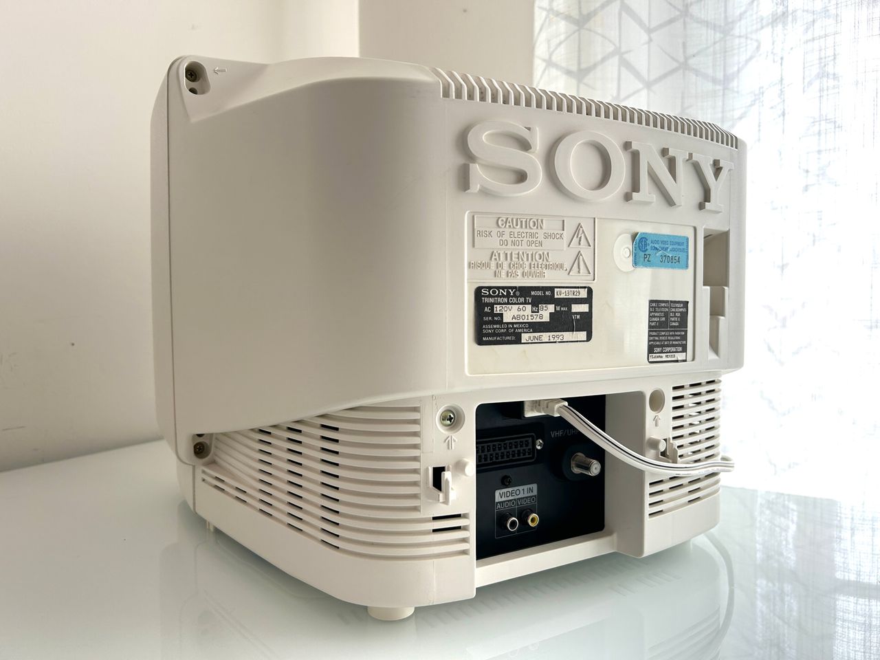
This is a classic 13" Sony Trinitron consumer television housed in a delightfully compact and charming plastic cabinet. Built around Sony’s BA-1 chassis, it represents an important early design in the Trinitron lineup and is widely regarded as the first Trinitron of this size that can be cleanly RGB-modded using the direct injection method.
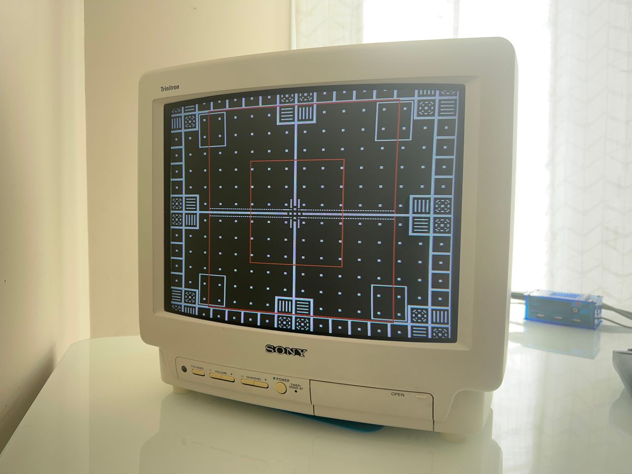
The BA-1 chassis is notably robust and thoughtfully laid out, making it easier to service and modify compared to many later Sony designs. Combined with the Hi-Black Trinitron tube, the set delivers excellent picture quality for its class, with strong geometry and vibrant color reproduction.
View full CRT details and more mod examples →
This tutorial should also cover the RGB mod for the below models with the BA-1 chassis. However, there might be slight differences.
13" models
- KV-13TR28 (black casing)
- KV-13TR29 (white casing)
- KV-13V50
Contributors
Thank you to everyone who contributed to this guide:
- Michael Lopez — showcase author
- Sunthar — showcase author
- Andy King — contributor, CRT specs from CRT Database.
- Patrick Buschur — contributor, Pictures
- stabarz — contributor, RGB mod tutorial on Reddit
CRT safety
Caution
You can die doing this! So read carefully! CRT TV is not a toy. Do not open a CRT TV. If you don't have any prior knowledge about handling high voltage devices, this guide is not for you. CRT TV contains high enough voltage (20,000+ V) and current to be deadly, even when it is turned off.
Plan of attack
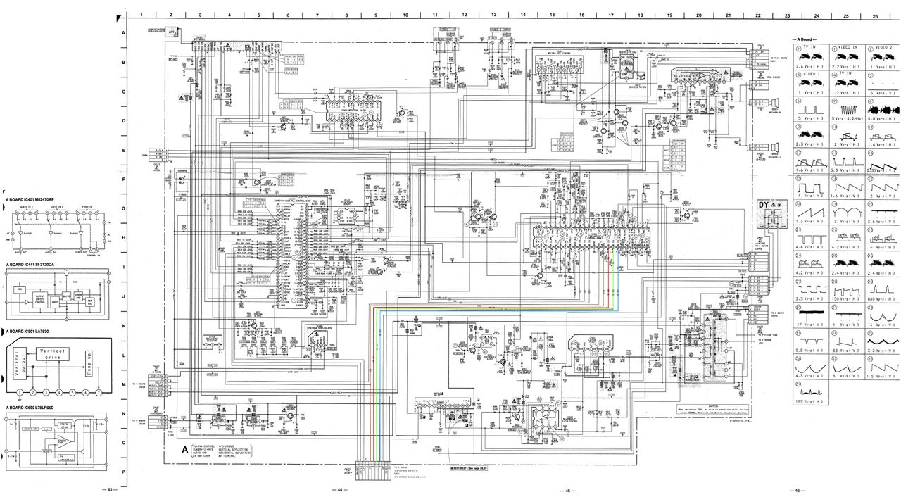
Manuals and Datasheets
Specs
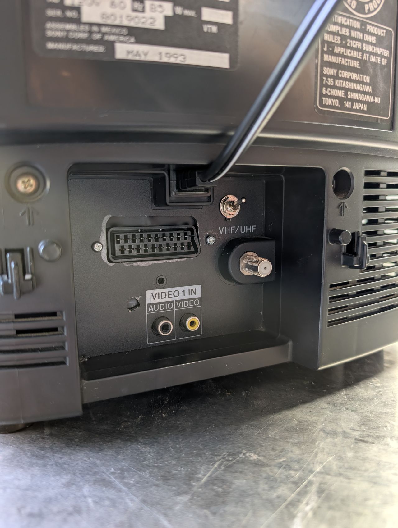
- Manufactured: Mexico (1993, 1994)
- Format: NTSC
- Chassis: BA-1
- Tube: Sony Trinitron A34JBU70X
- Jungle Chip: Sony CXA1465AS
- Screen Size: 13"
- Weight: 24 lbs
- Inputs: Composite, RF
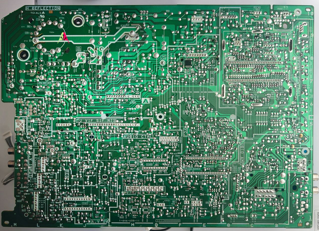
RGB mux diagram
Prepare the mux diagram. If you are building your own circuit, this diagram should help.
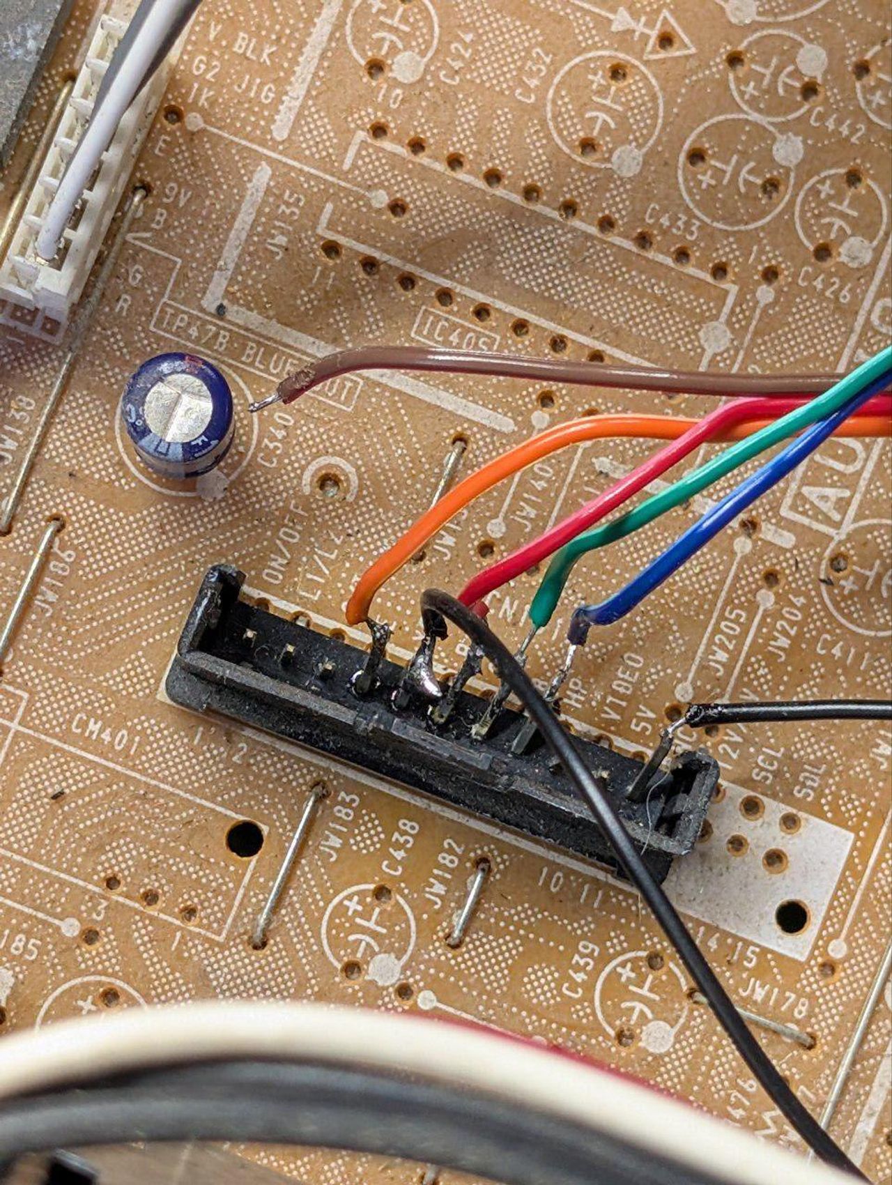
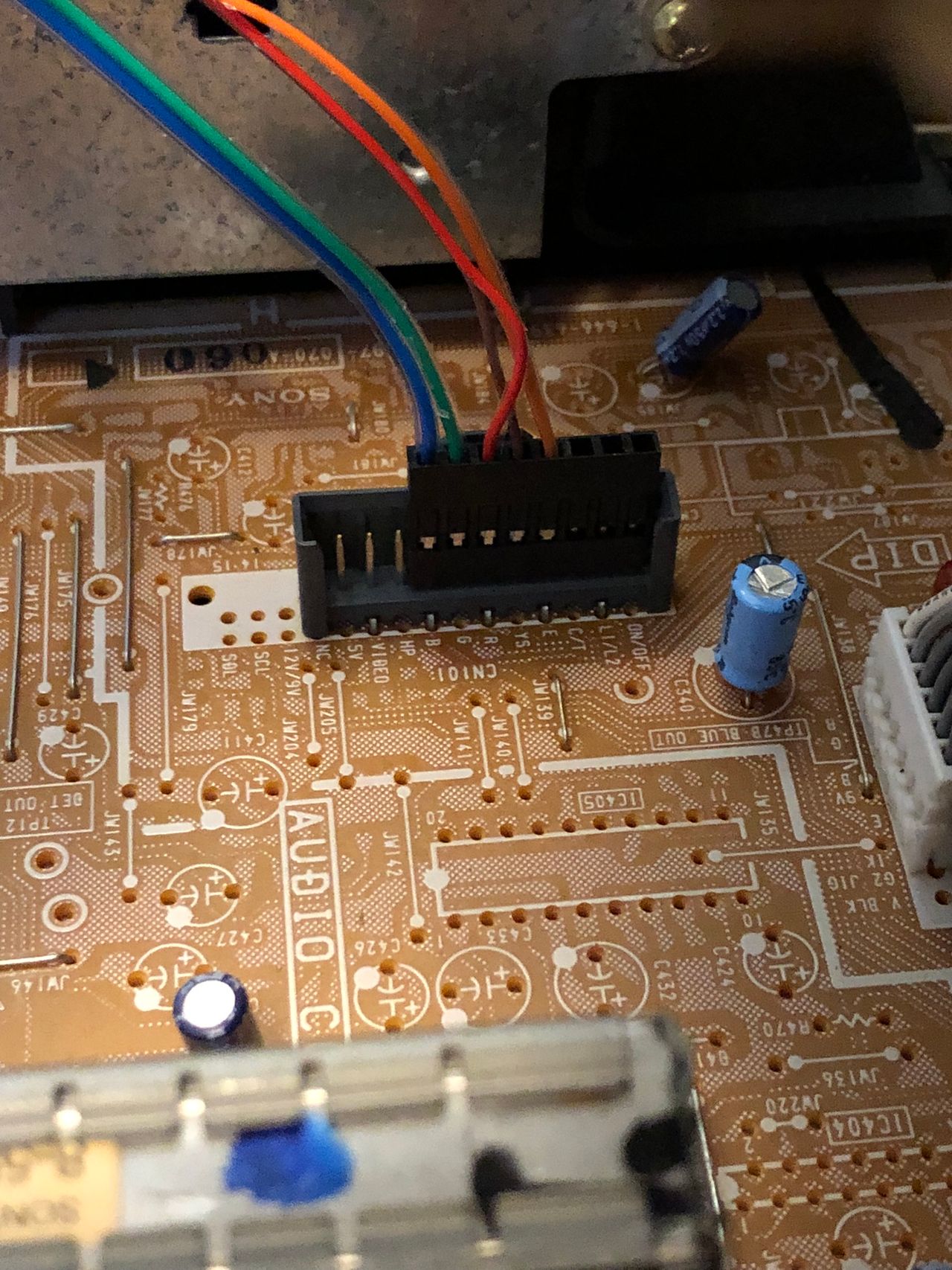
Red is shown for reference. Blanking (Ys), Red, Green, Blue lines are exposed on 5, 6, 7, 8 of the CN101 connector.
Performing the mod
You can't ask for a more straightforward RGB mod.
Fortunately this chassis doesn't require any muxing. You can pass R, G, B through a 0.1uF, 75ohm terminated wire directly to the CN101 header. Blanking (Ys) can be fed through a 1kΩ + 0.7V didoe to pin 5 of the CN101 header.
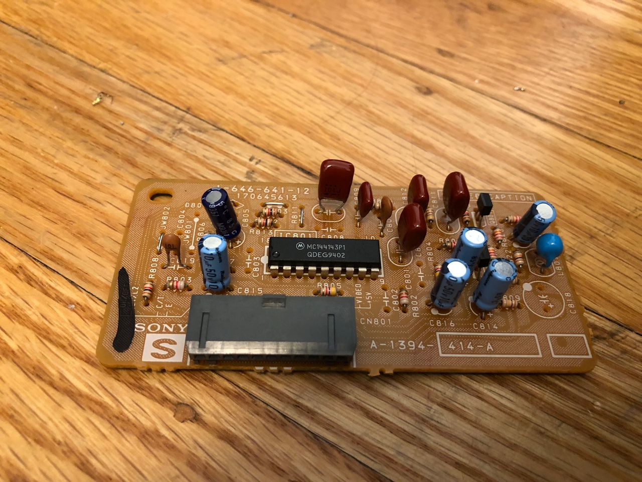
STEP 1: Remove Closed Captioning Decorder board
The Closed Captioning Decoder board (the "S" board) has to be removed prior to the modification on the United States version of this set (and other Sony BA-1 chassis sets).
In the service menu, the ID-2 setting was changed from "64" to "0" to disable Closed Captioning after performing the mod.
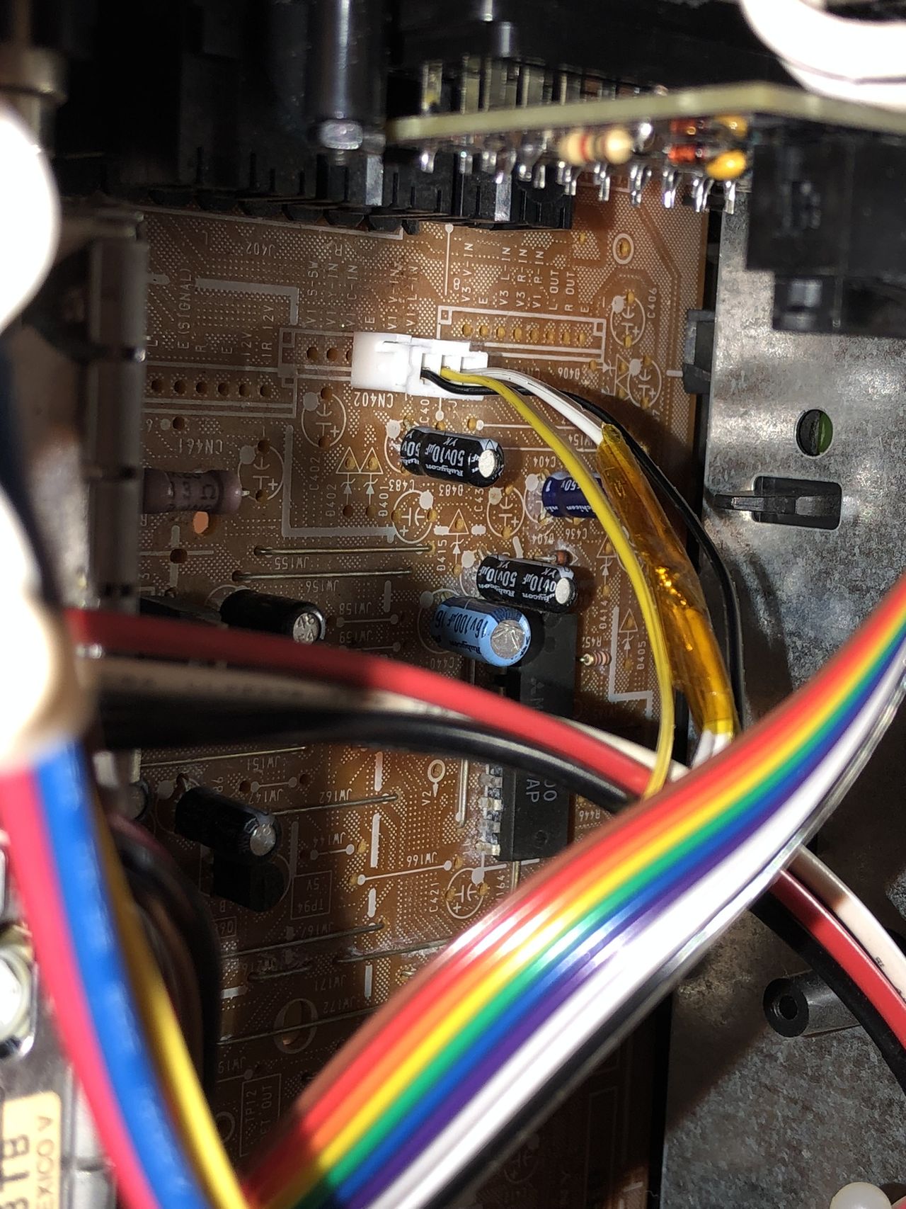
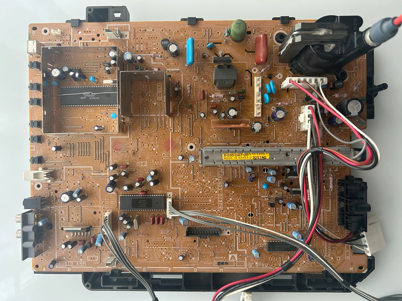
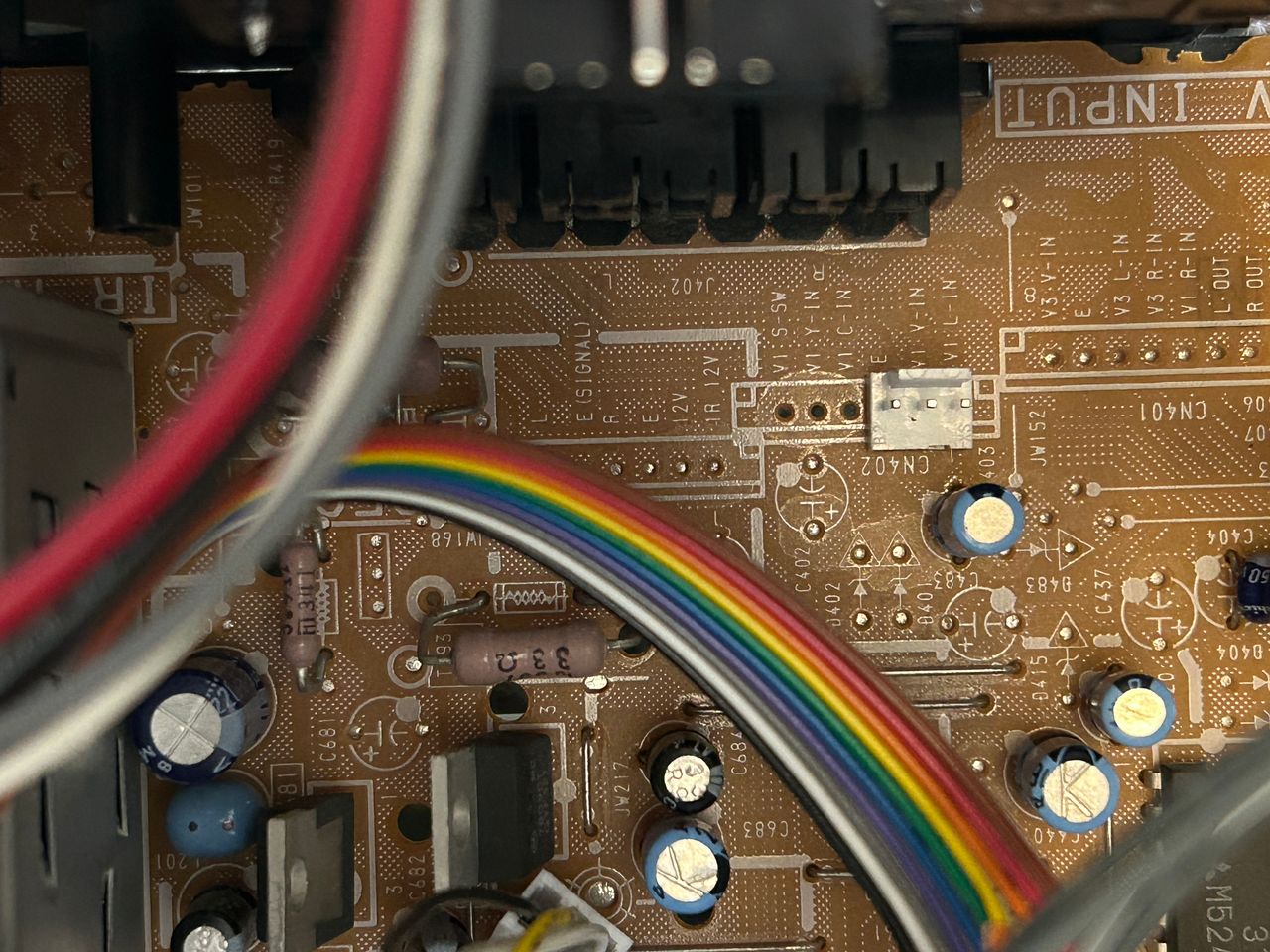
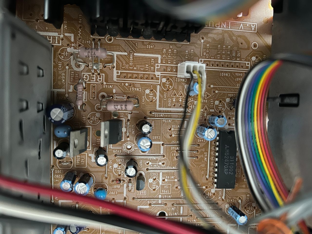
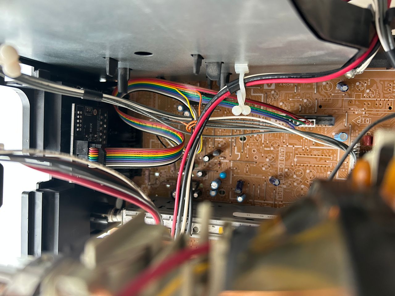
STEP 2: Connect RGB, Blanking and Ground
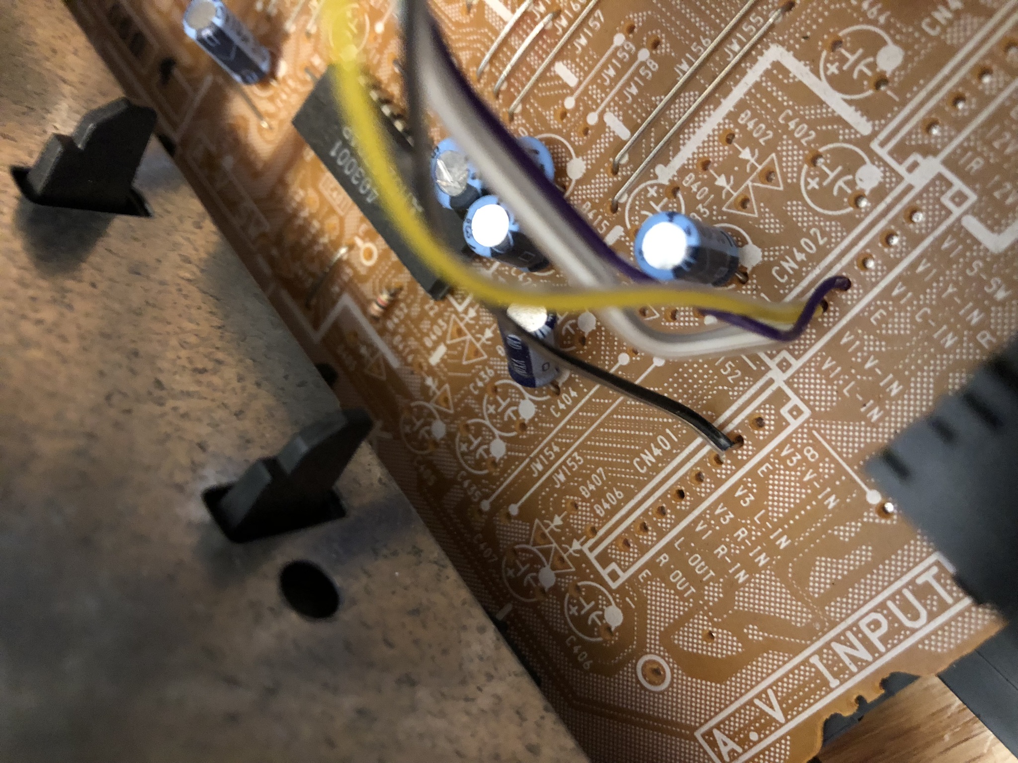
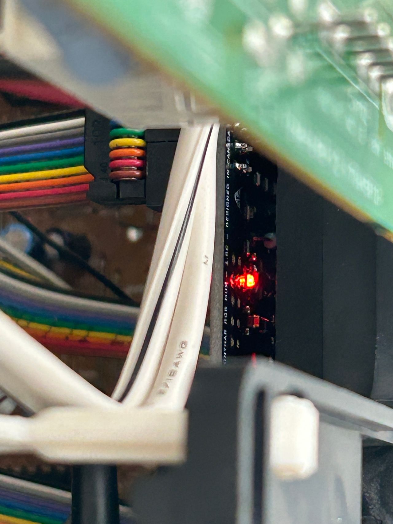
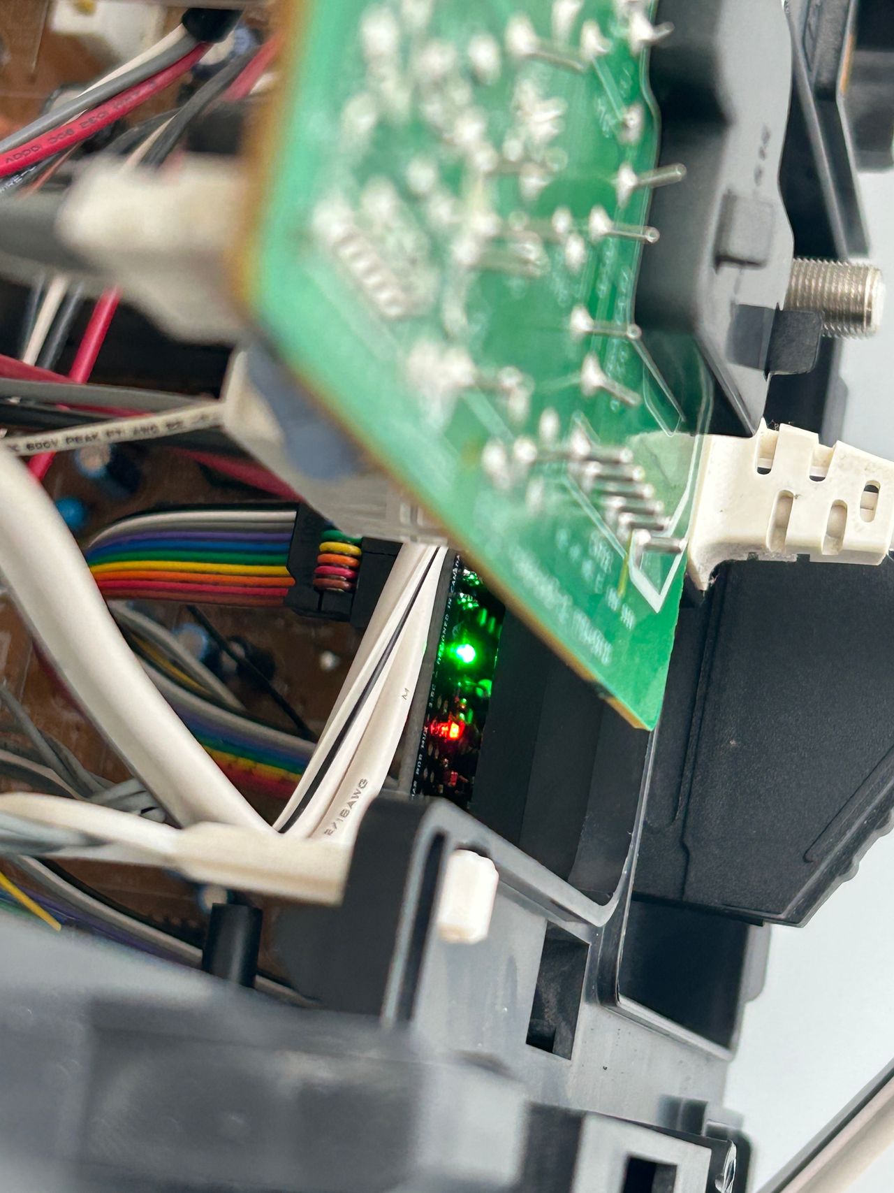
See picture to see where blanking, R, G, B should be connected. Blanking (Ys), Red, Green, Blue lines are exposed on 5, 6, 7, 8 of the CN101 connector.

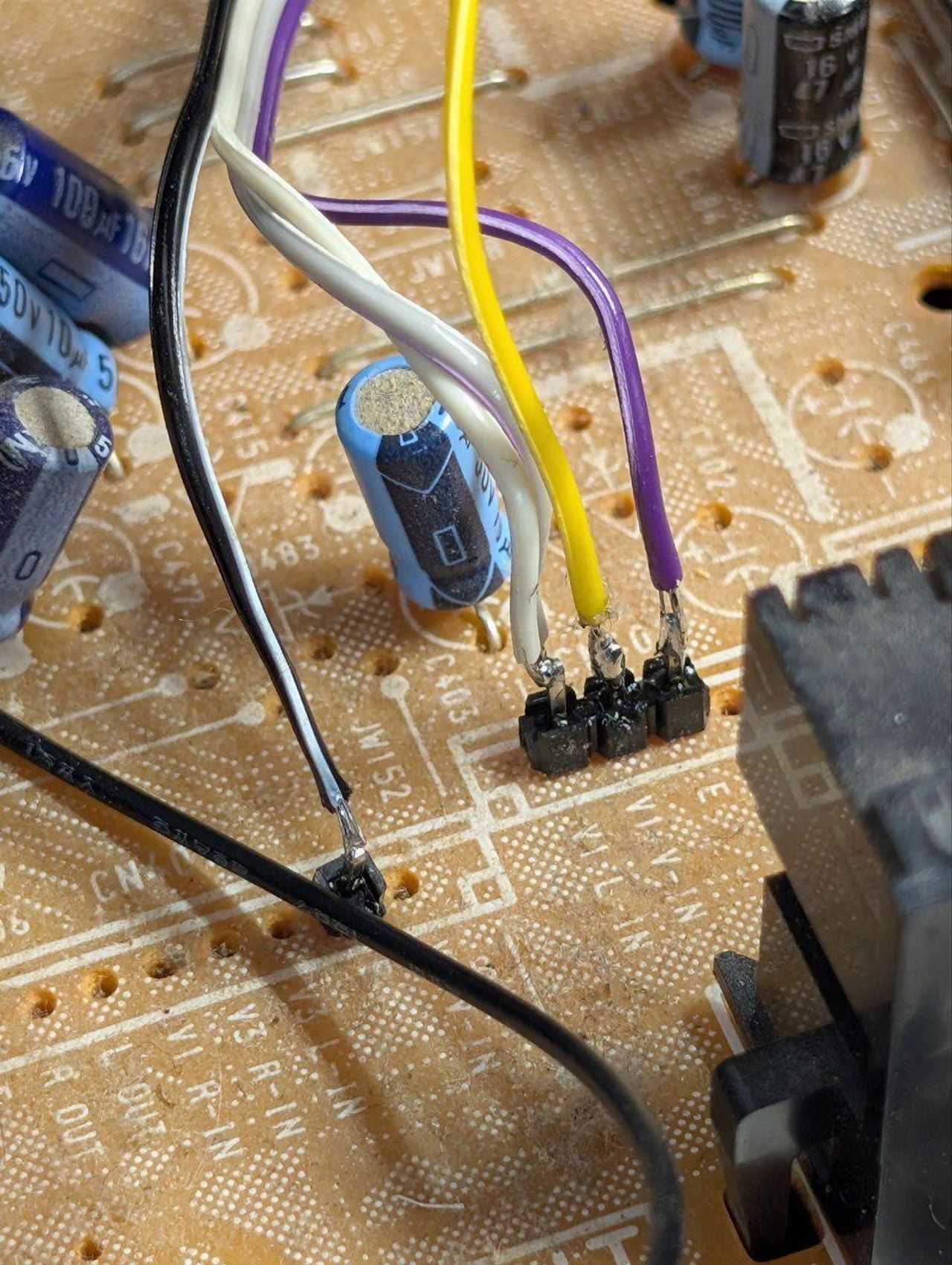
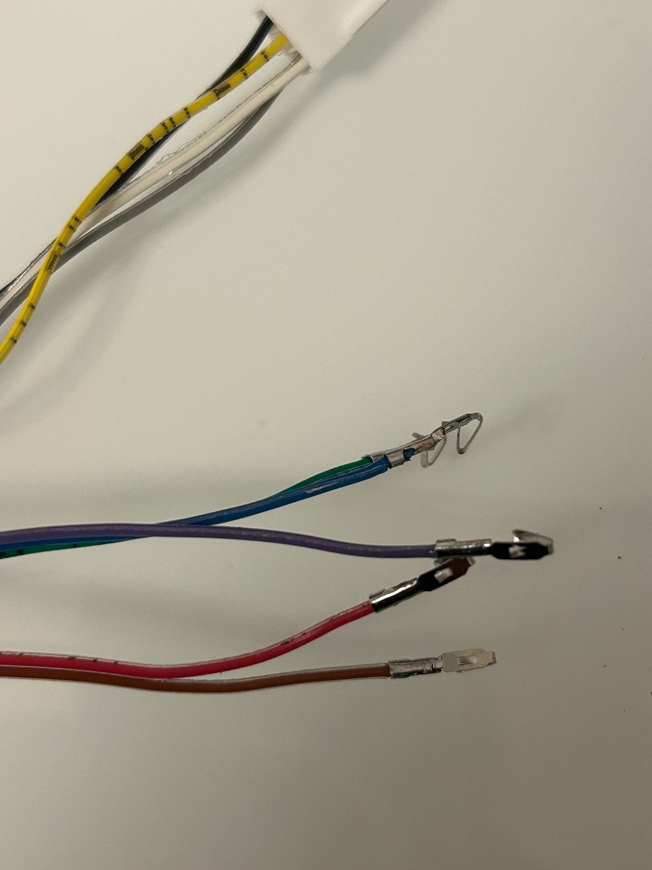
STEP 3: Connect Audio and Sync
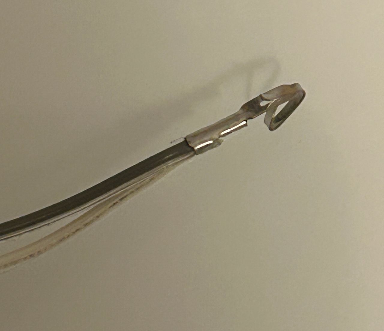
Since this set only supports mono audio, the Audio Left (white) and Right wires (grey) were twisted together and soldered onto the "V1 L-IN" pad on the mainboard.
- V1 V-IN for SYNC
- V1 L-IN for Left and Right Audio
- E for GROUND
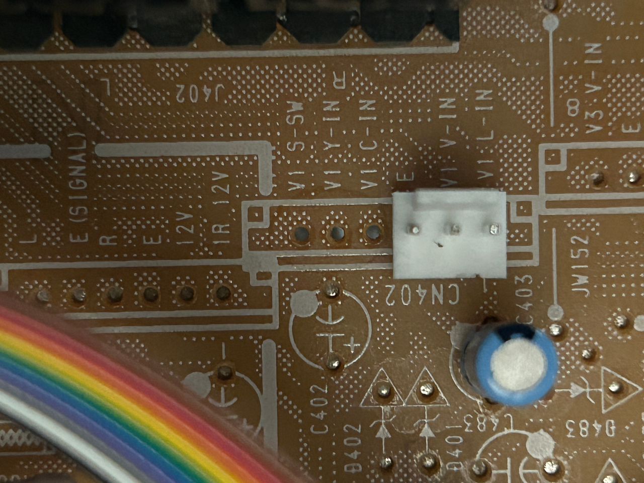
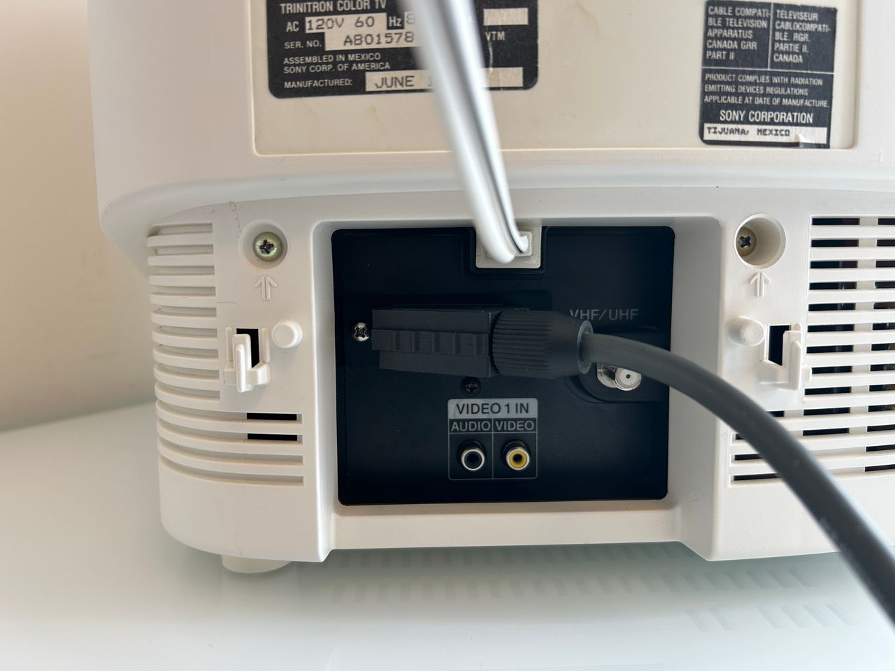
Below photo taken from Sony KV-13TR29, shows a JST connector placed on the appropriate spot for a header on the chassis. 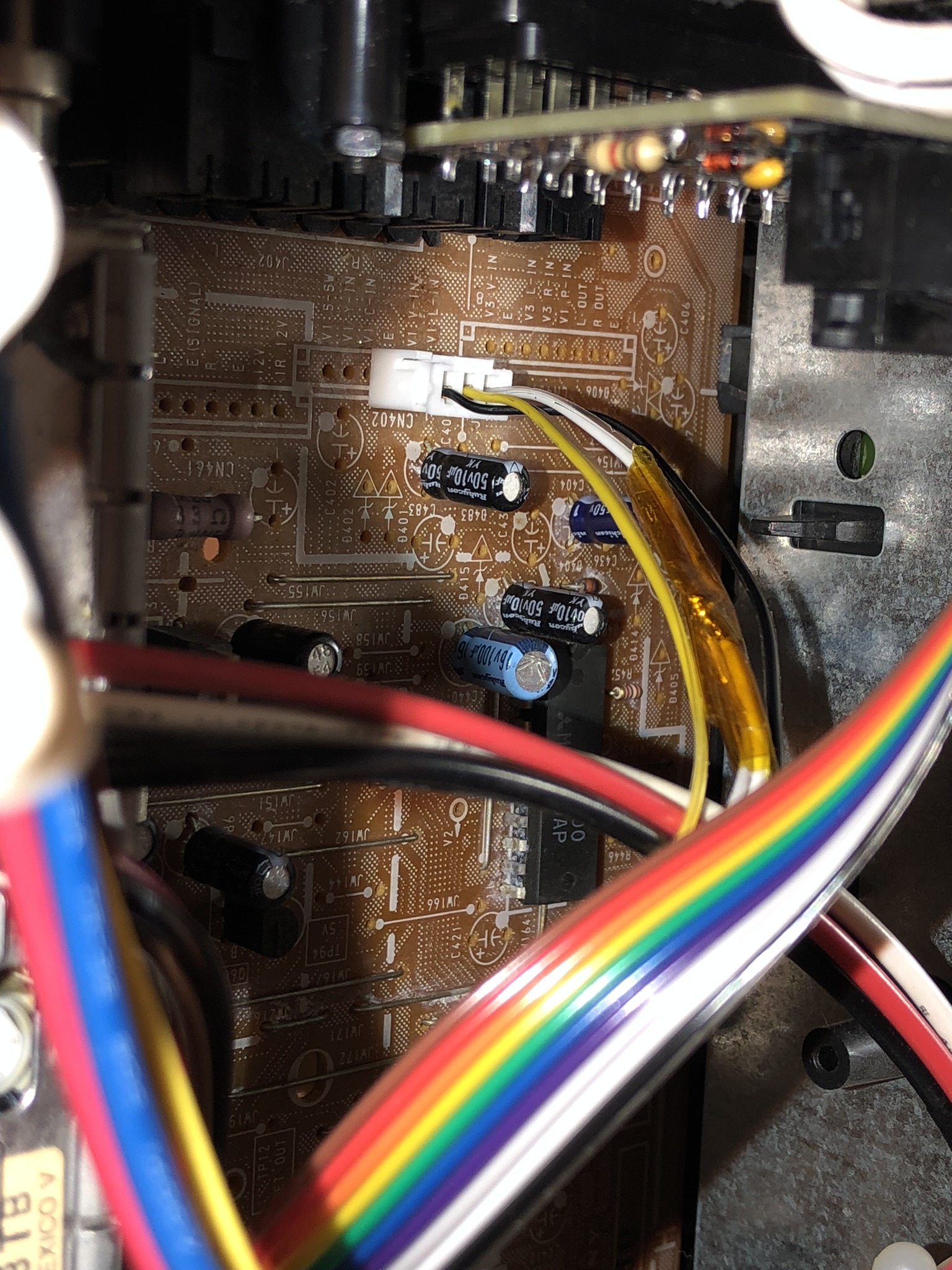
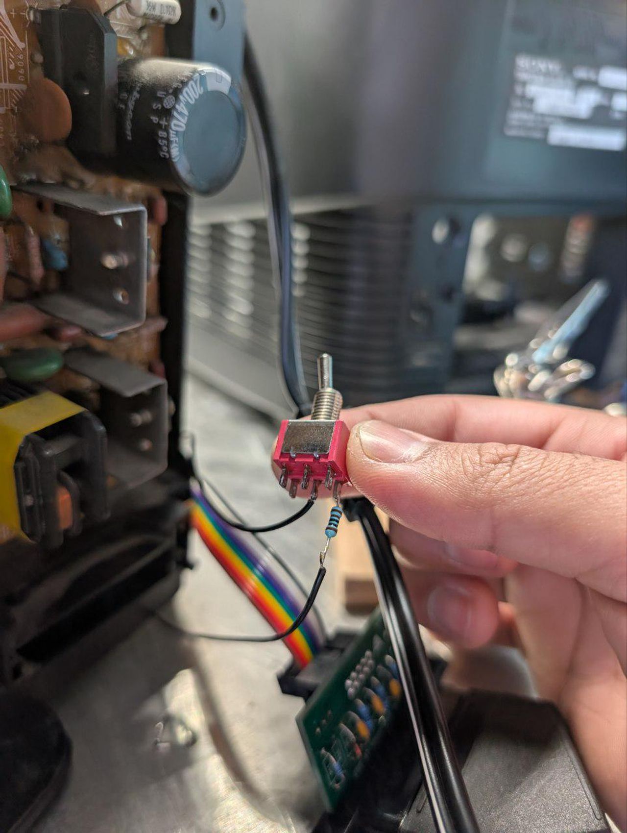
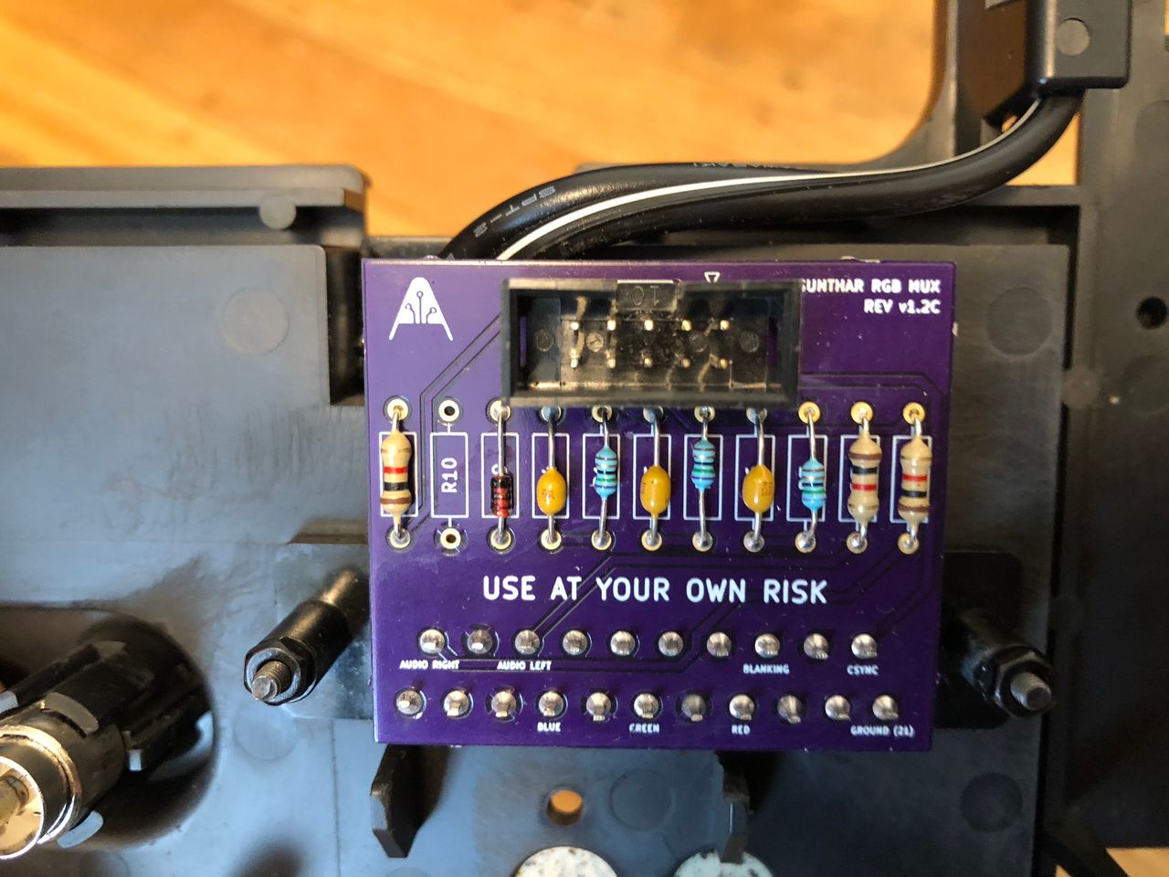
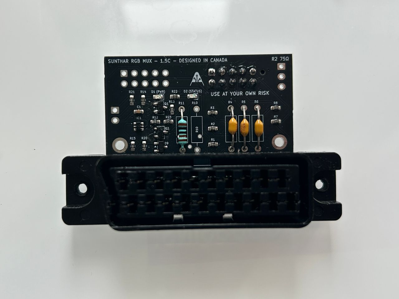
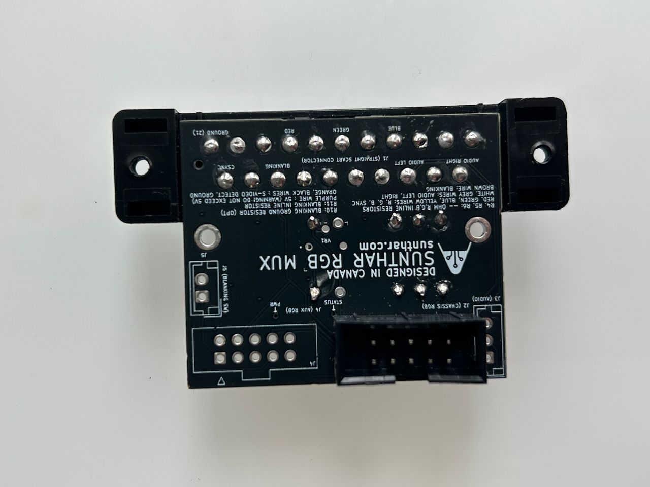
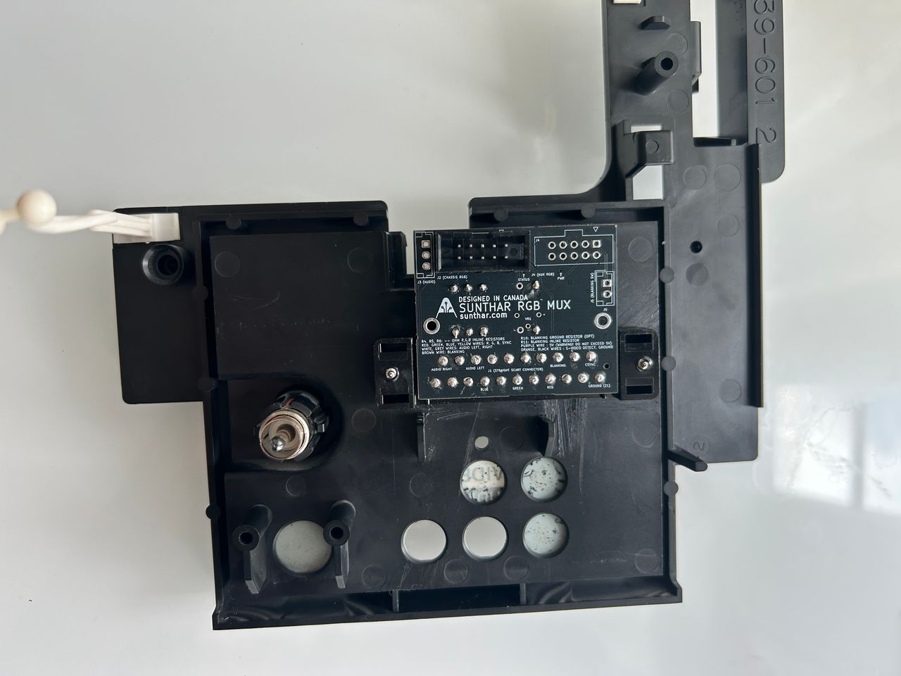
STEP 4: Build your mux board (optional)
This mod uses the RGB mux board. This is optional, but will make your mod easier and stable. You can also create the circuit presented in the schematics above without the board. Please also checkout the mux calculator to play with your own values.
| On Sony CRT Chassis | KV-13TR28 |
|---|---|
| 0.1μF caps replaced | No |
| Add diodes on chassis RGB lines? | No |
| Add blanking diode on chassis | No |
| RGB mux board | KV-13TR28 |
|---|---|
| Mux board RGB termination (R1, R2, R3) | 75Ω |
| Mux board RGB input capacitors (R4, R5, R6) | 0.1μF |
| Mux board Audio LR (R7, R8) | 1kΩ |
| Mux board blanking diode (R9) | 1N4148 |
| Mux board blanking ground resistor (R10) | open |
| Mux board blanking resistor (R11) | 1kΩ |
Compatible mux boards:
What's shown in the below picture is the 1.3C mux board kit. You can use either 1.3C or 1.4C mux board kit for this mod.

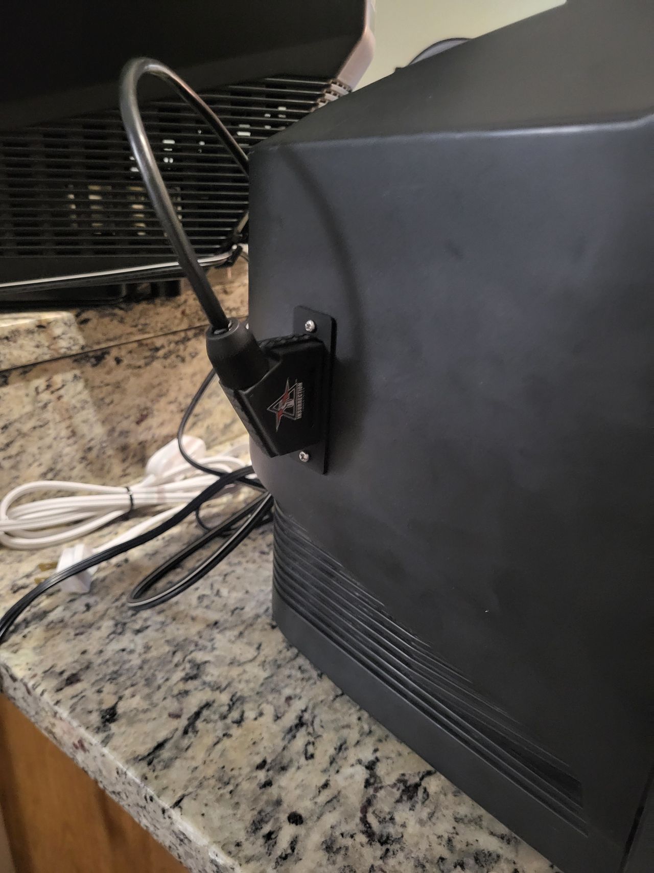
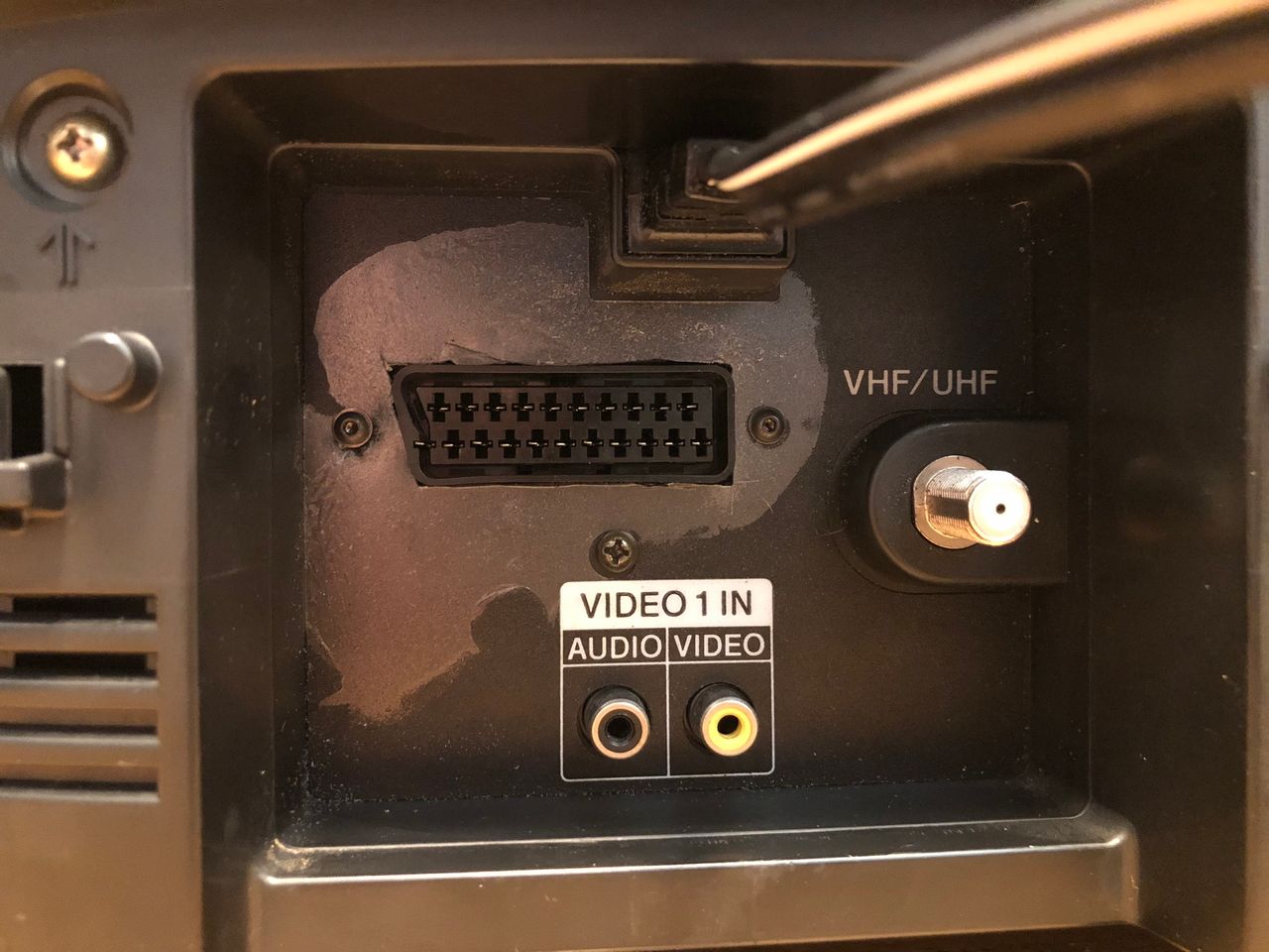
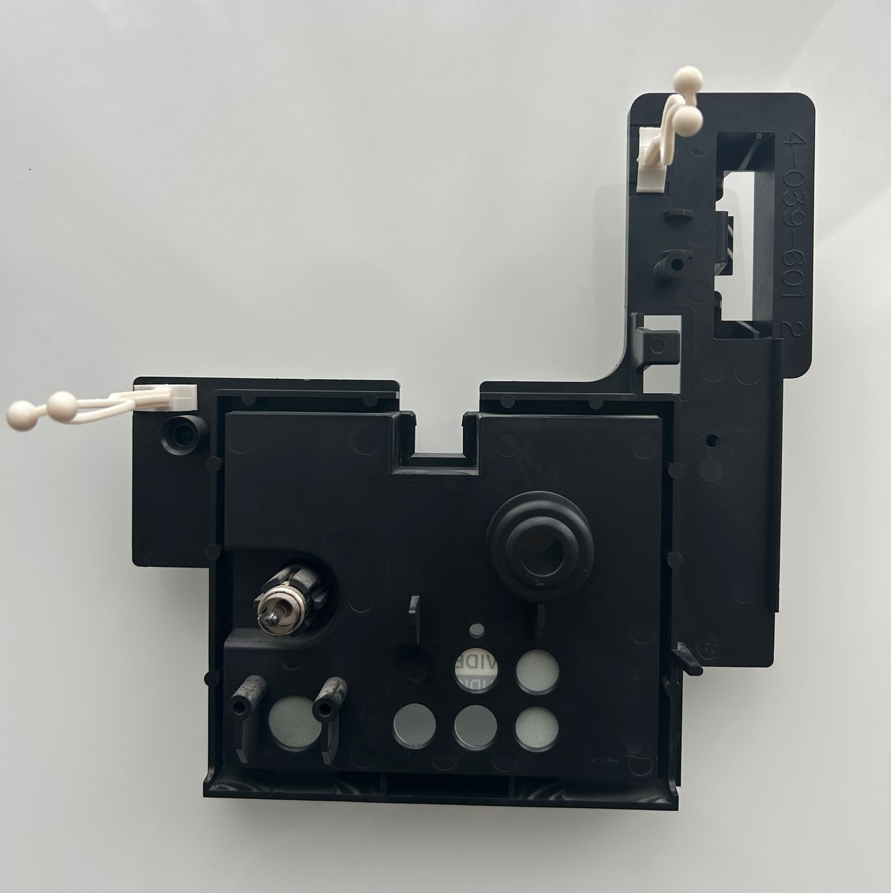
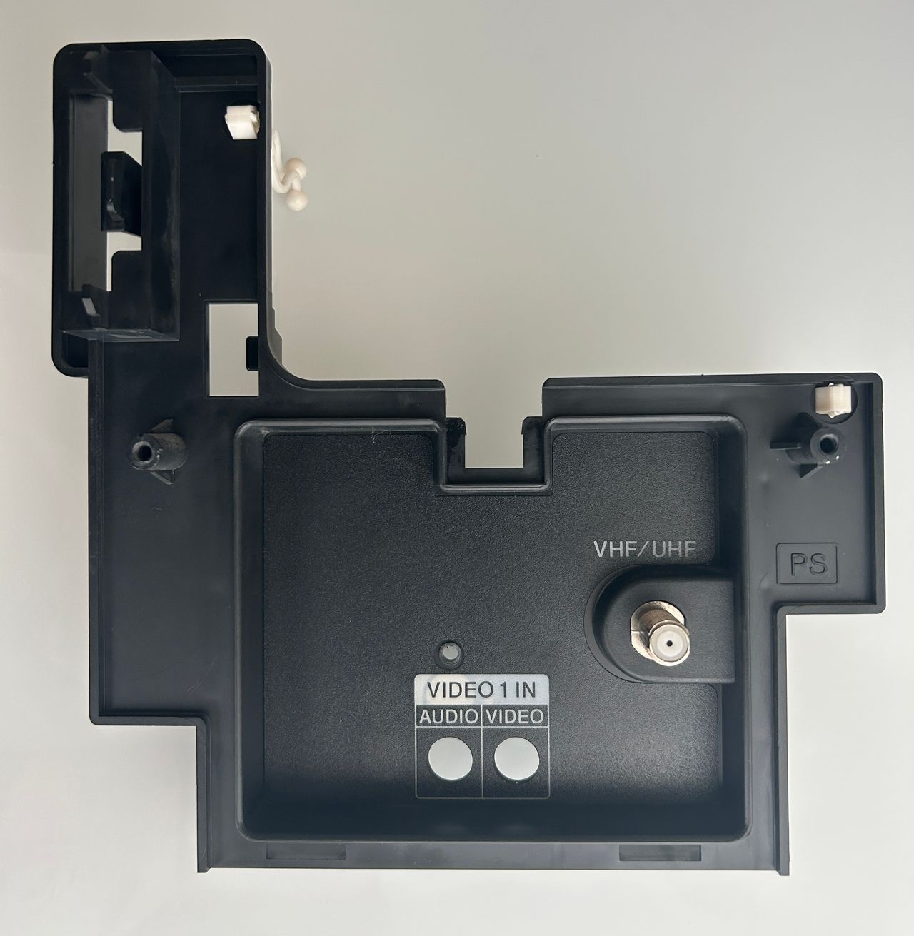
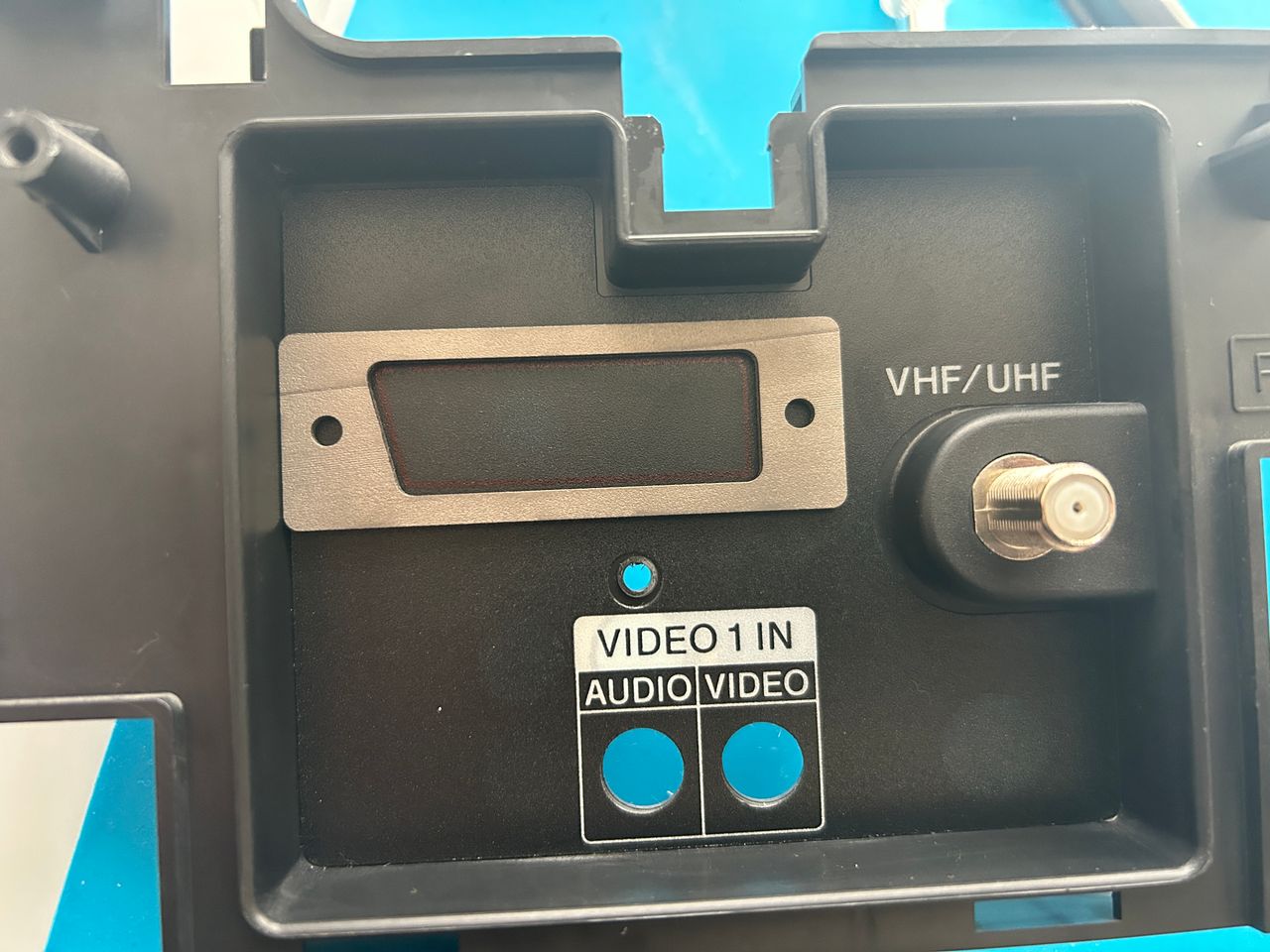
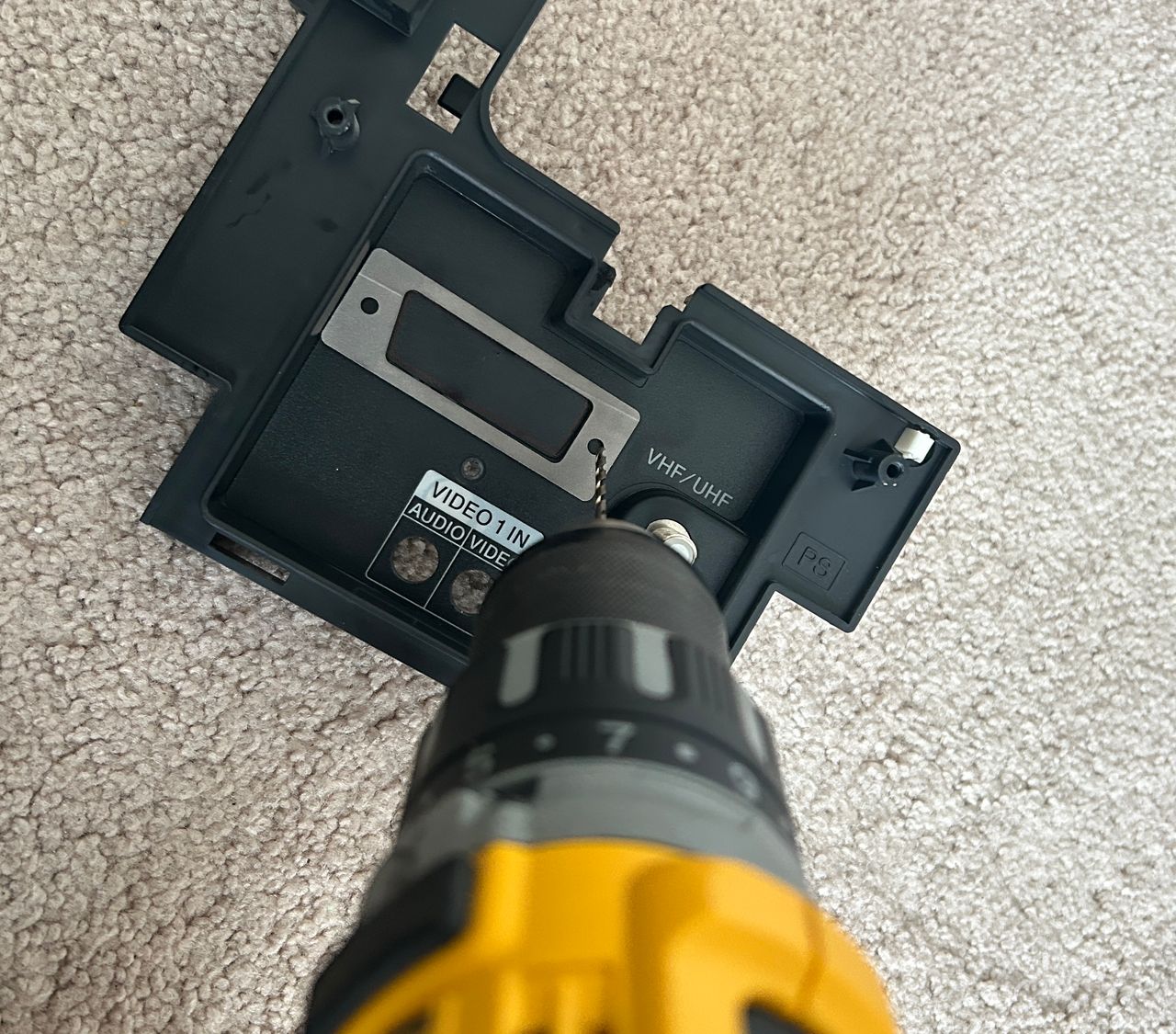
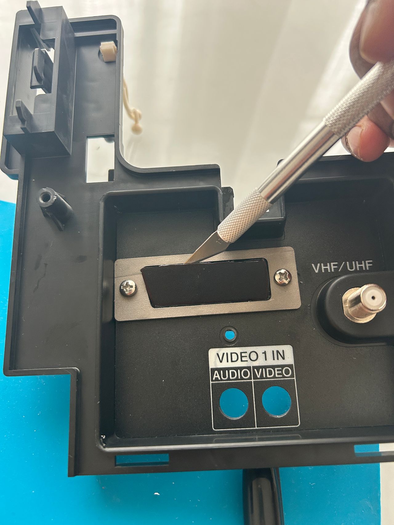
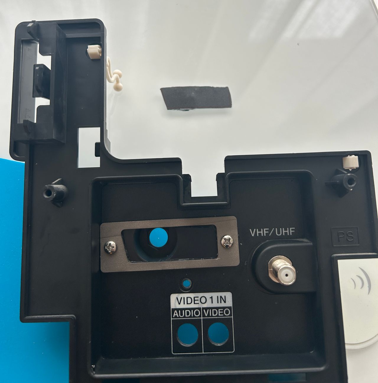
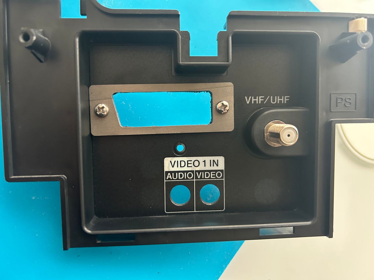
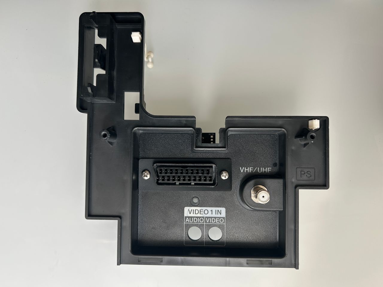
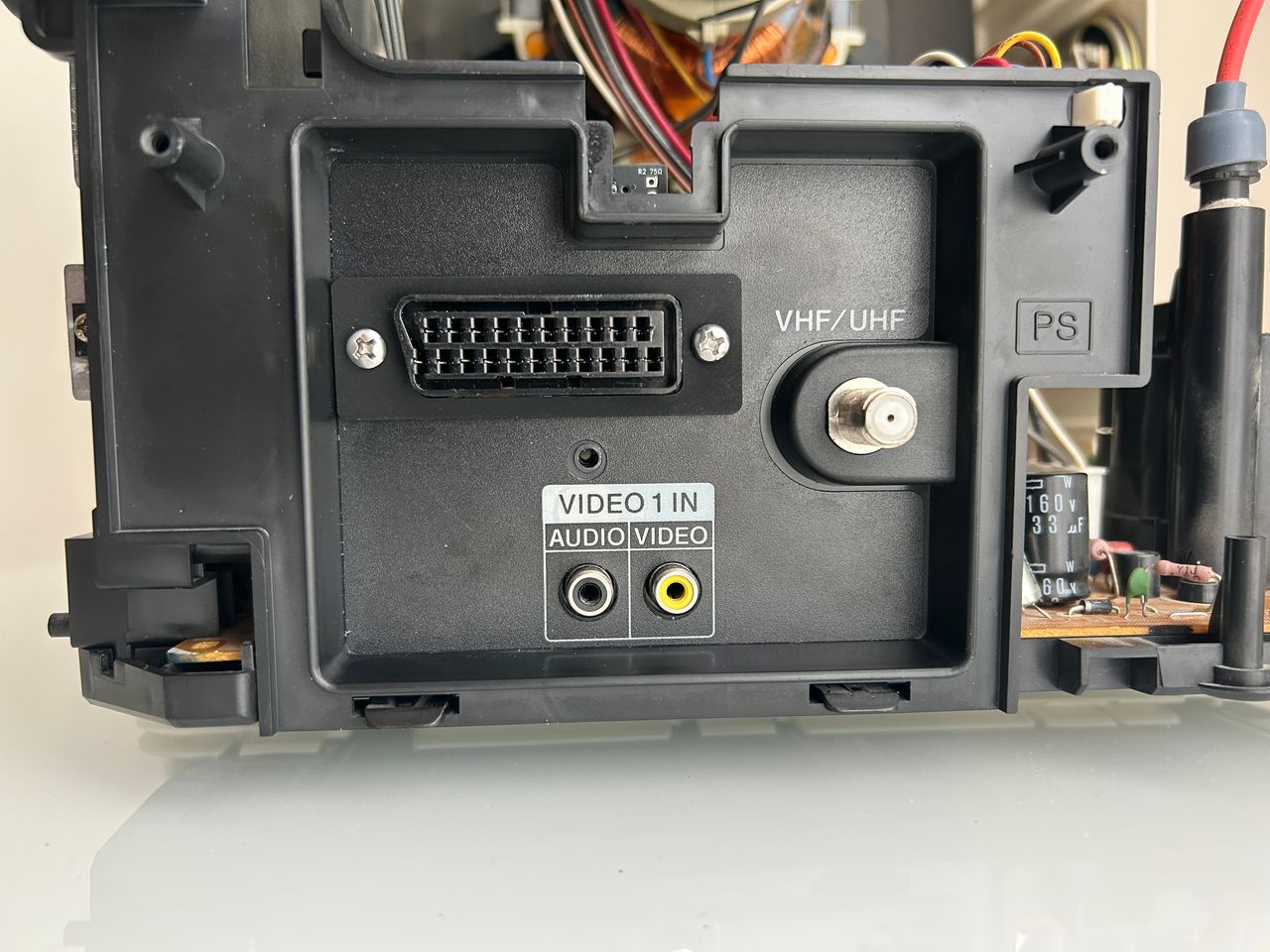
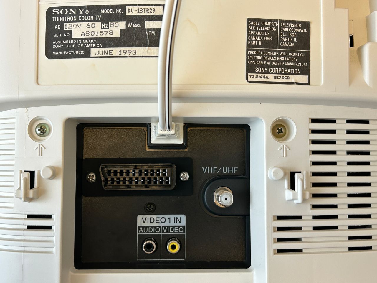
STEP 5: Attach the female SCART connector to TV
There is a sticker at the back that made it very difficult to cut the SCART port. Cutting this port is probably most complex part of this mod.
Creating a SCART cutout and mounting it is an art. I have a dedicated section for it.
How to create and mount a SCART female plug?
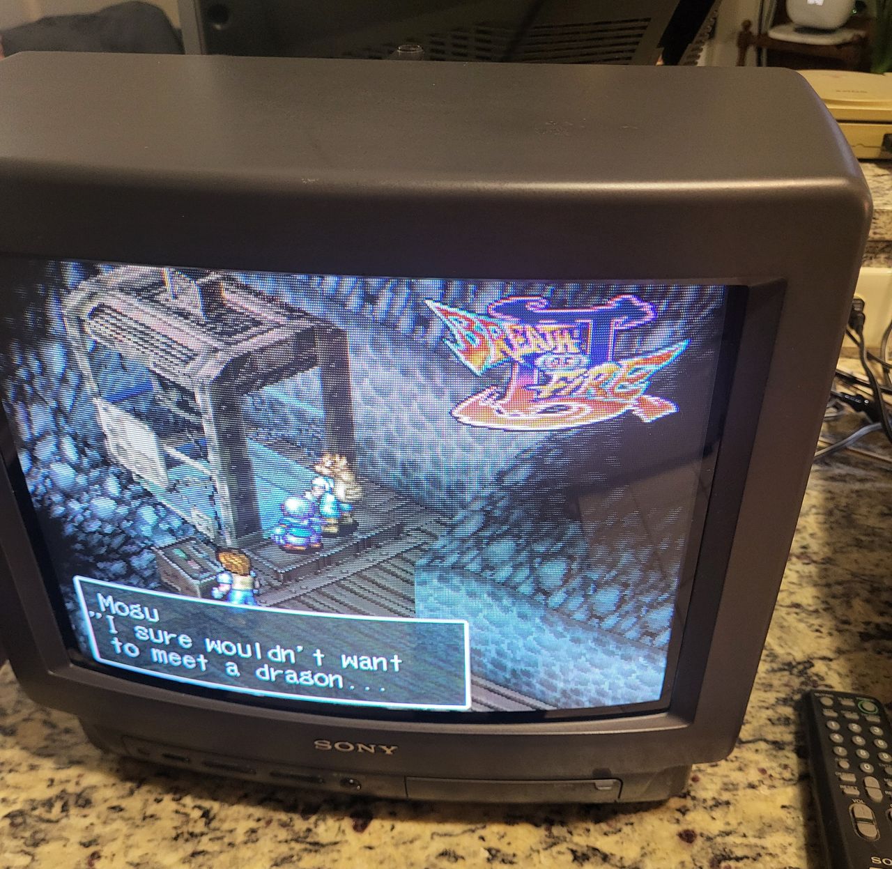
Pictures
Photos by Michael Lopez
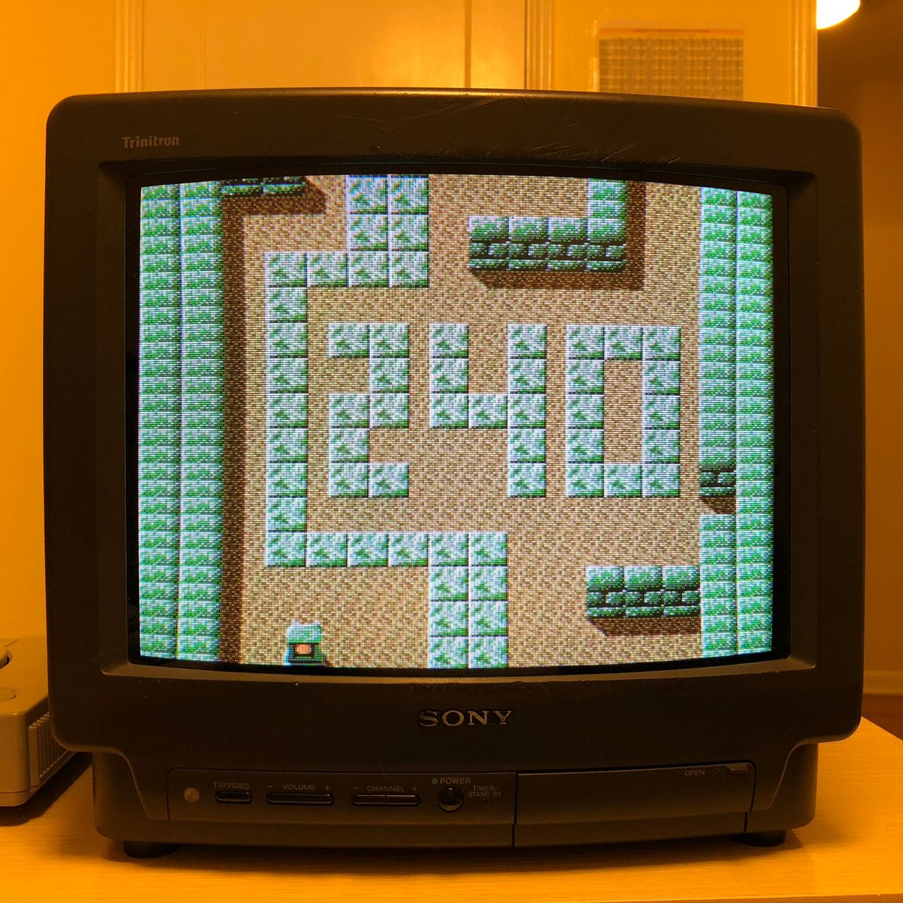
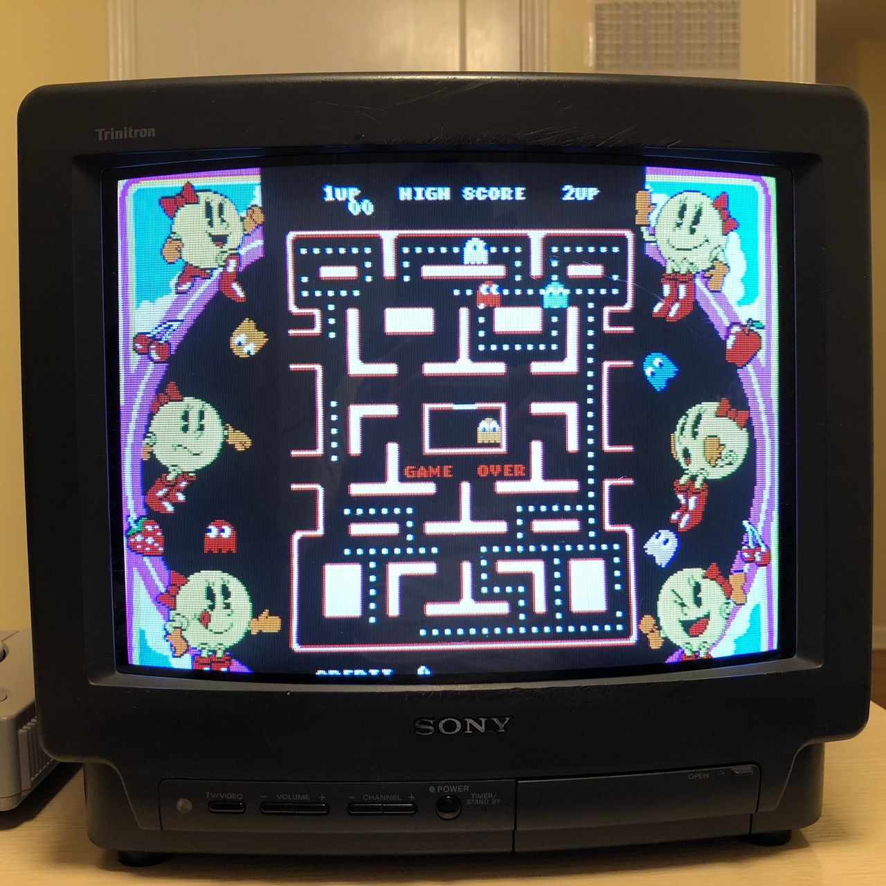
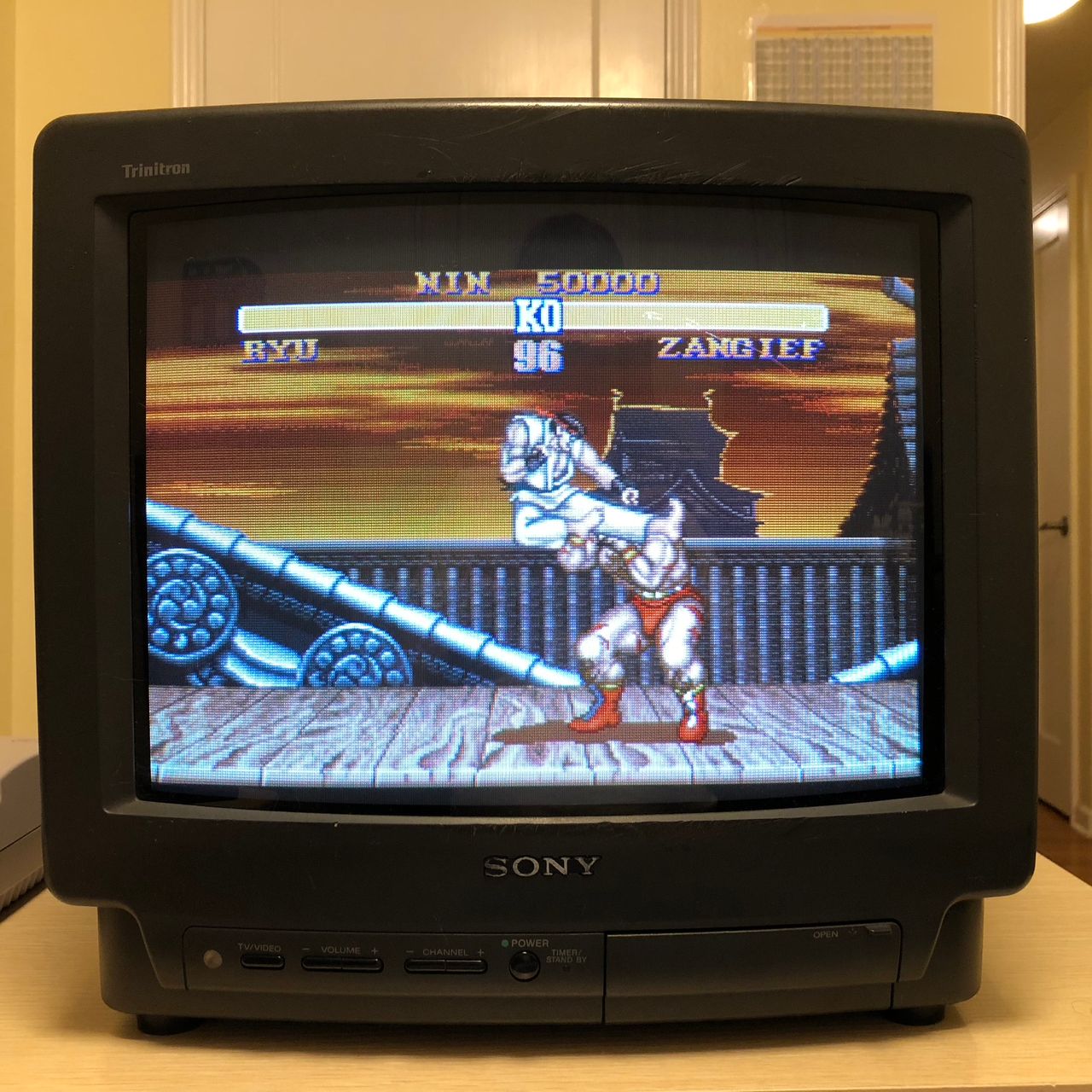
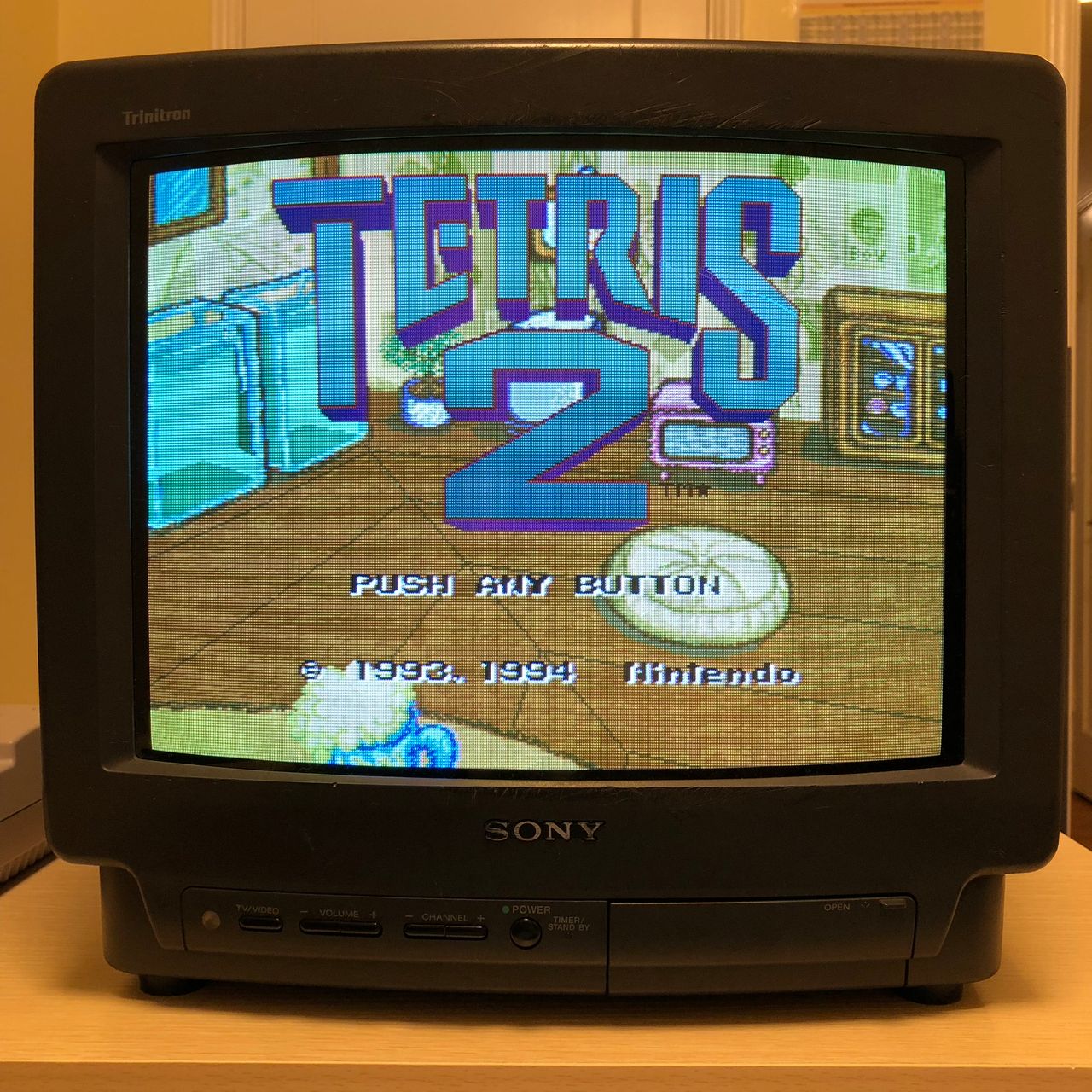
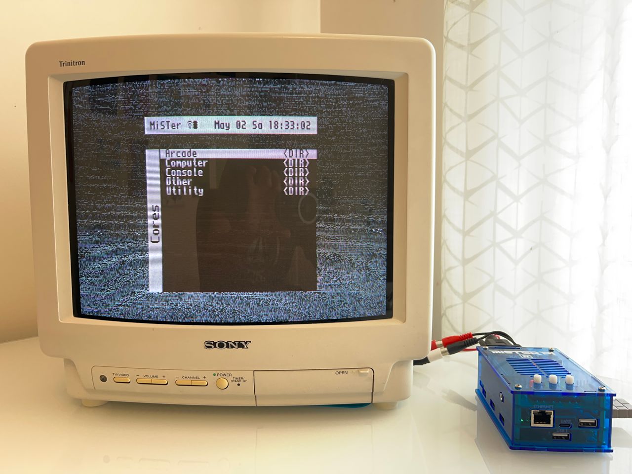
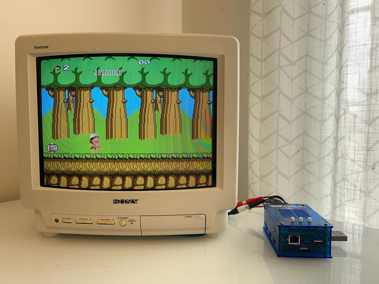
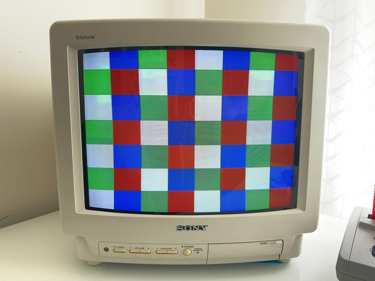
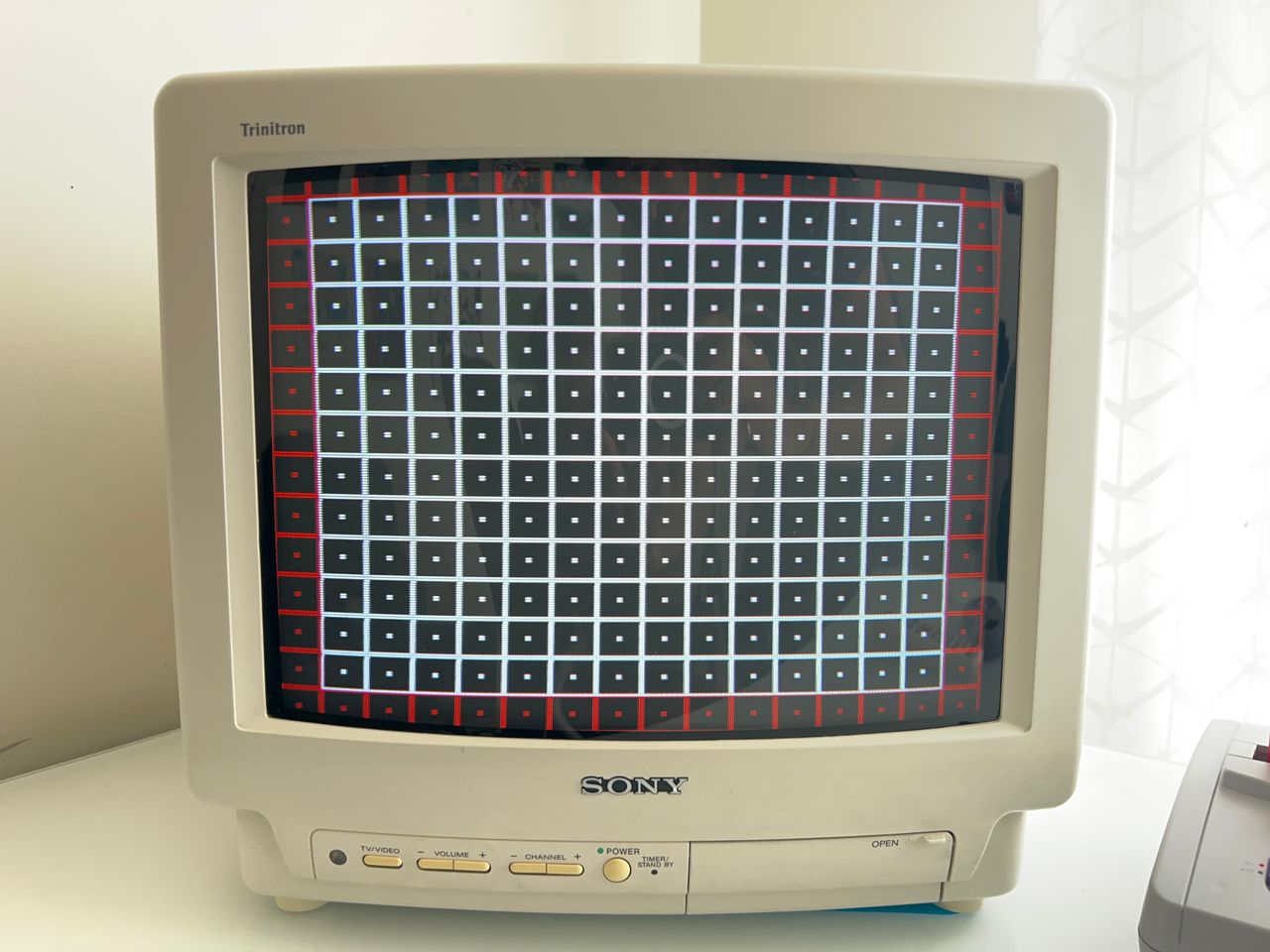
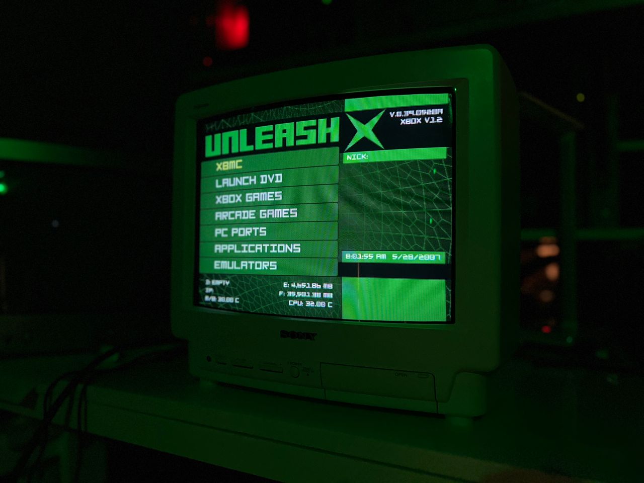
Sony KV-13TR28 is a basic 13" CRT. It is a perfect candidate for RGB modding given that it only has composite and RF inputs.
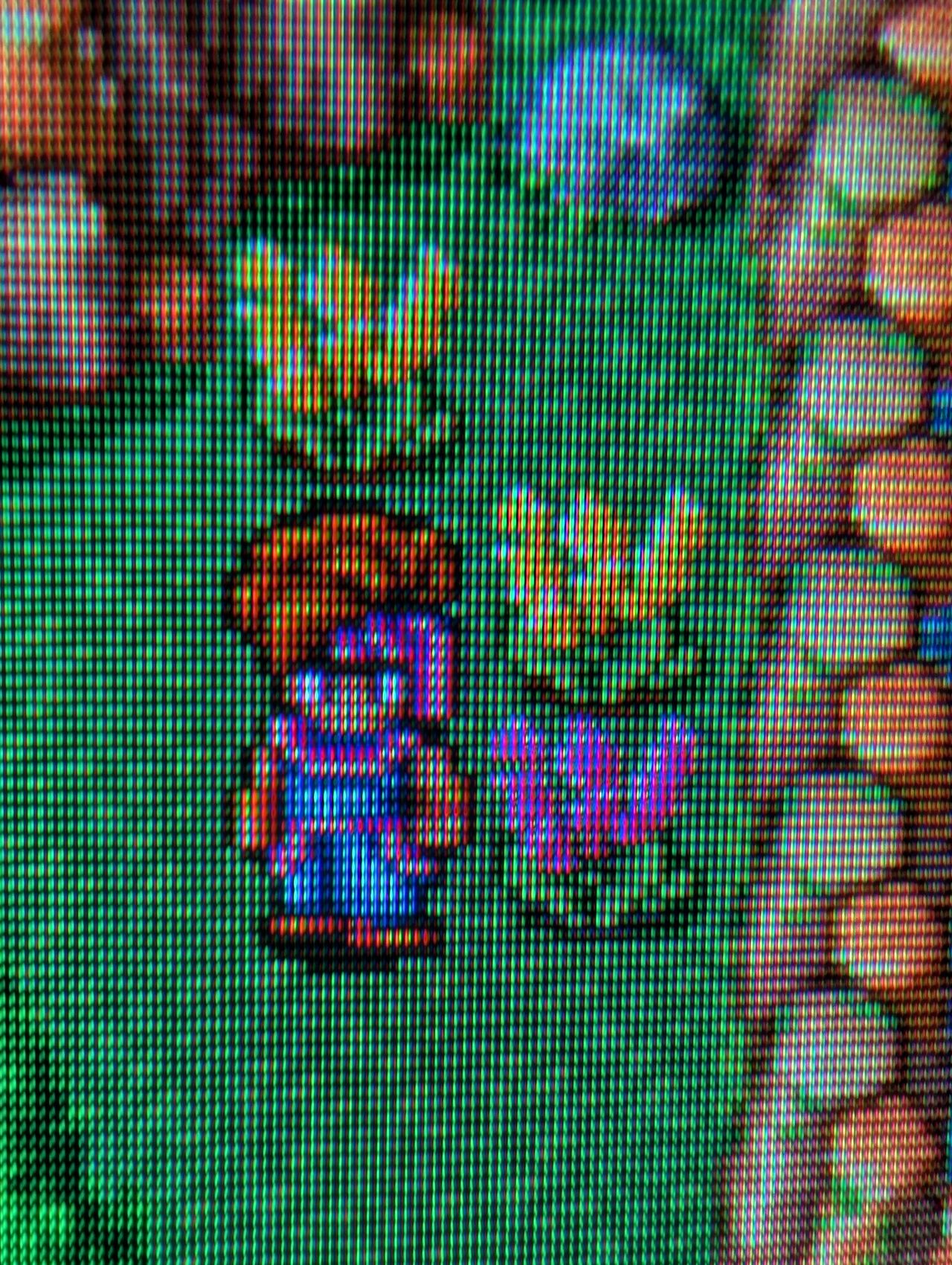
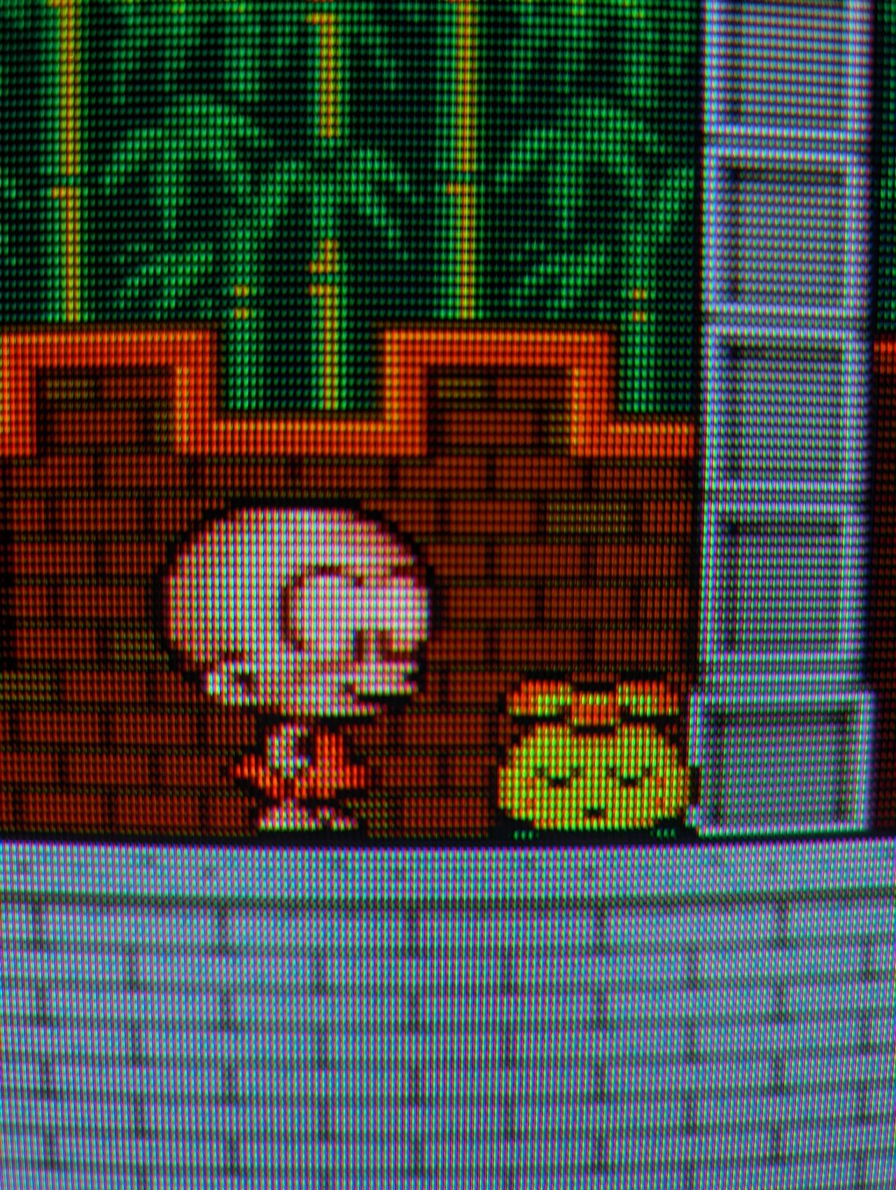
Mod Photos

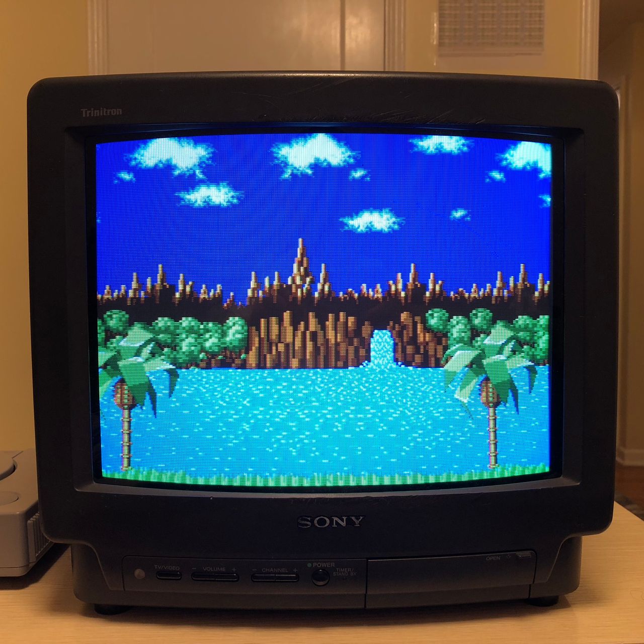


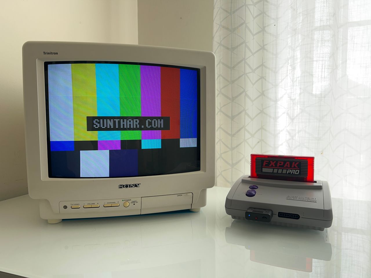
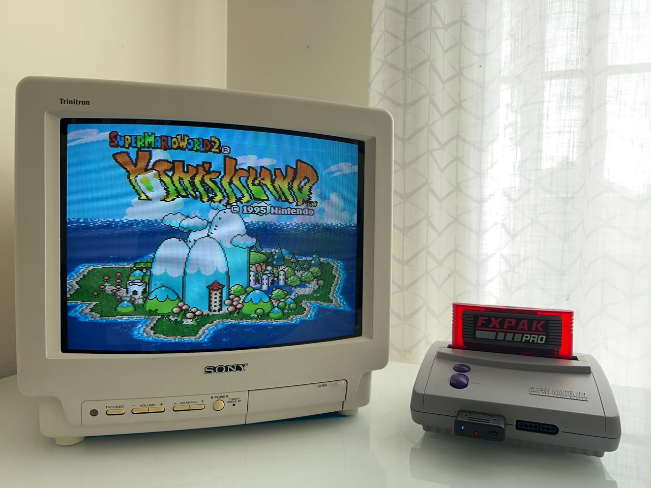
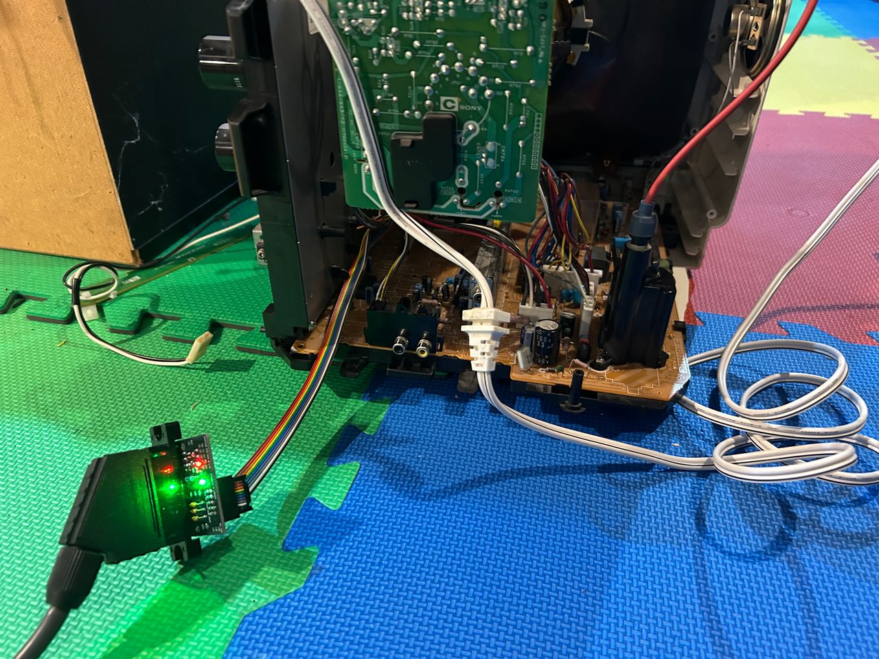
Photos by Sunthar
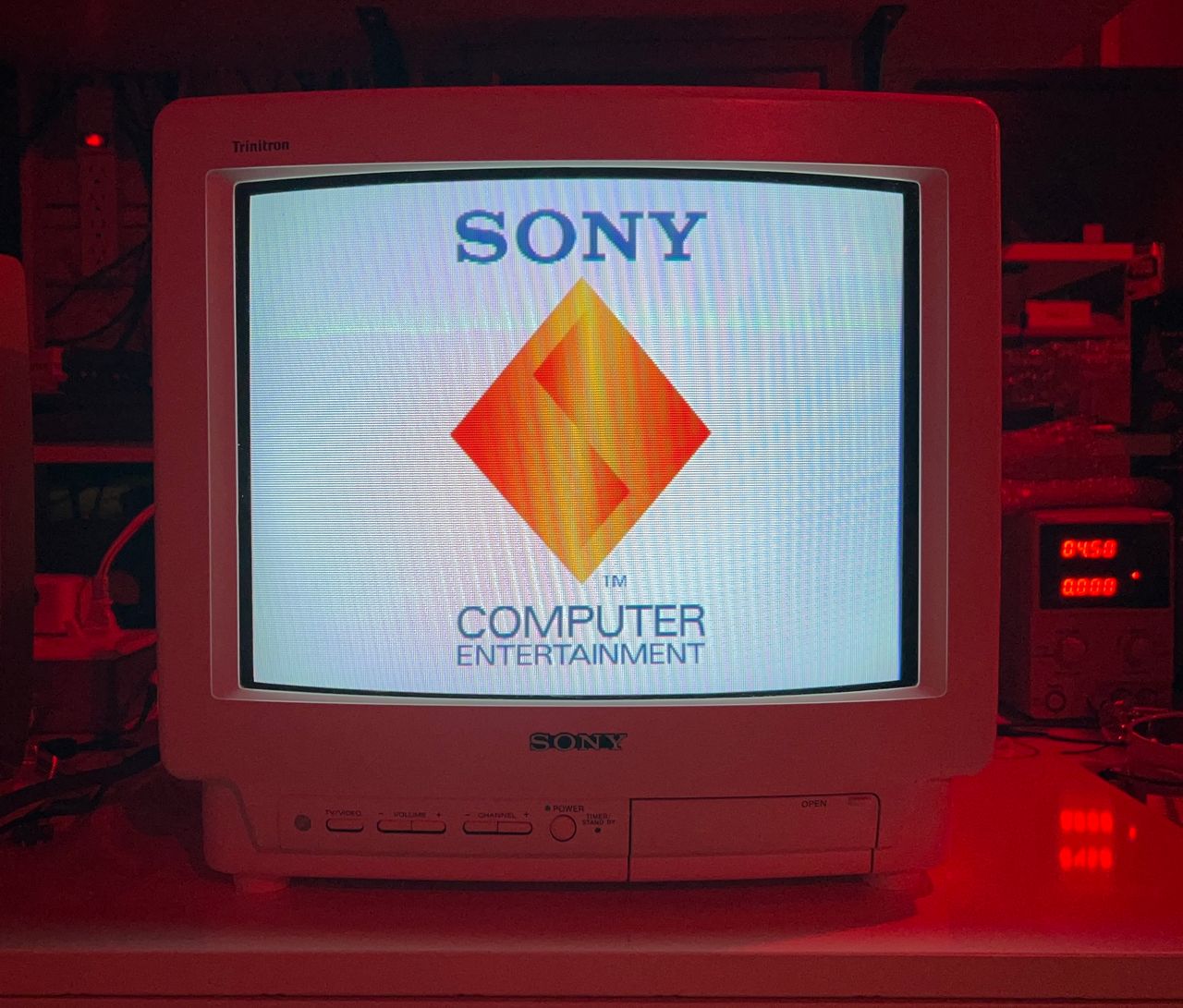
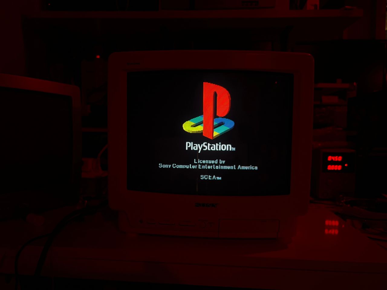
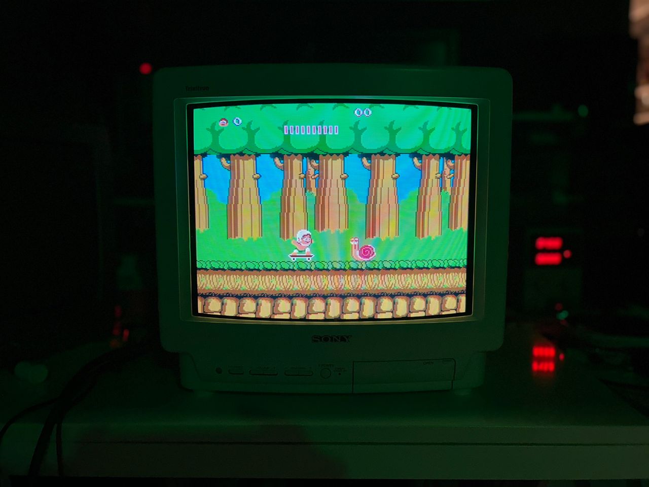
Used the latest 1.5C board to modify this set. Worked amazingly well. Tested with 3V blanking input from MisterPi and the set was able to switch.


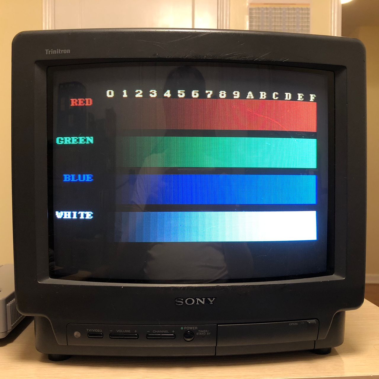
Reference Photos