Sony (BA-4) KV-20M40
Sony (BA-4) KV-20M40 CRT RGB mod + Component YPbPr
The Sony KV-20M40 is a 20" Trinitron color CRT television manufactured in the late 1990s, known for its reliability and quality. It operates on a versatile BA-4 chassis, making it popular among enthusiasts for modifications.
View full CRT details and more mod examples →
Contributors
Thank you to everyone who contributed to this guide:
- Davide Bacchet — showcase author
- Matt Ross — contributor, CRT specs from CRT Database.
CRT safety
Caution
You can die doing this! So read carefully! CRT TV is not a toy. Do not open a CRT TV. If you don't have any prior knowledge about handling high voltage devices, this guide is not for you. CRT TV contains high enough voltage (20,000+ V) and current to be deadly, even when it is turned off.
Plan of attack
Manuals and Datasheets
Specs
- Year: 1997
- Format: NTSC
- Chassis: BA-4
- Tube: Sony Trinitron A51LDG50X
- Jungle Chip: Sony CXA2061S
- OSD Chip: M37273MF-252SP
- Screen Size: 20"
- Inputs: Composite, RF
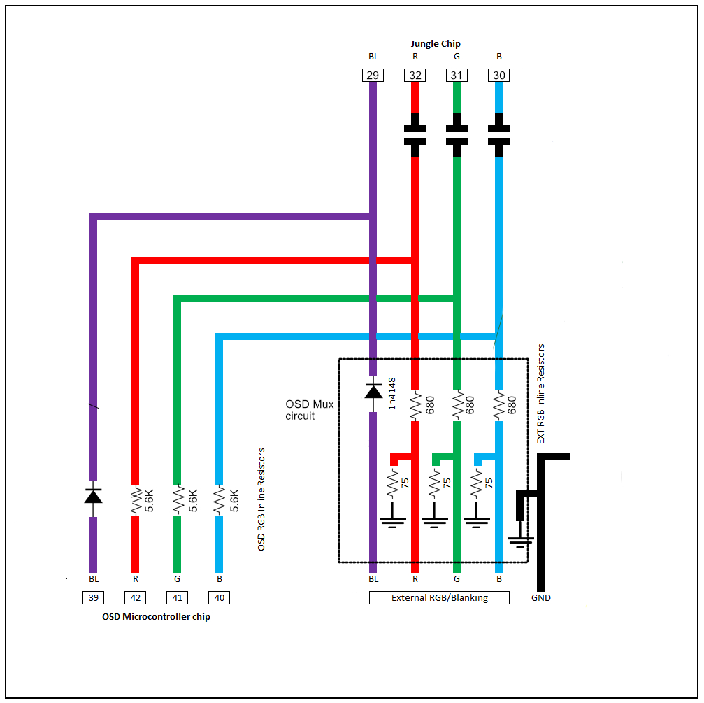
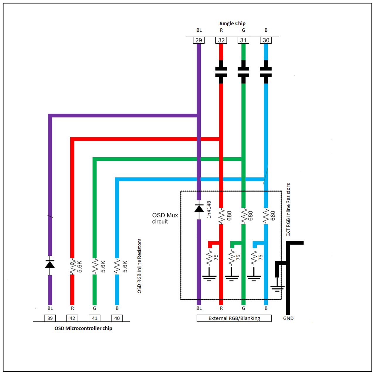
RGB mux diagram
Prepare the mux diagram. If you are building your own circuit, this diagram should help.
Performing the mod
Below mod was performed by Davide Bacchet. If you are using the Sunthar RGB mux board, please follow the KV-20S42 tutorial instead. There might be slight differences between 20" and 27" BA-4 chassis. For 20" you may want to sync through composite instead of luma.
 A friend brought me a very nice Sony Trinitron KV-20M40, that he wanted to mod. This set has a BA4 chassis that is very flexible so we decided to perform a dual mod, and add both RGB and Component support to this nice 20".
To make things a little more interesting, I wanted to be able to select RGB and Component using the remote, and not a physical switch on the back of the TV. Luckily that's possible with this TV. The result is that at the end we have a TV with:
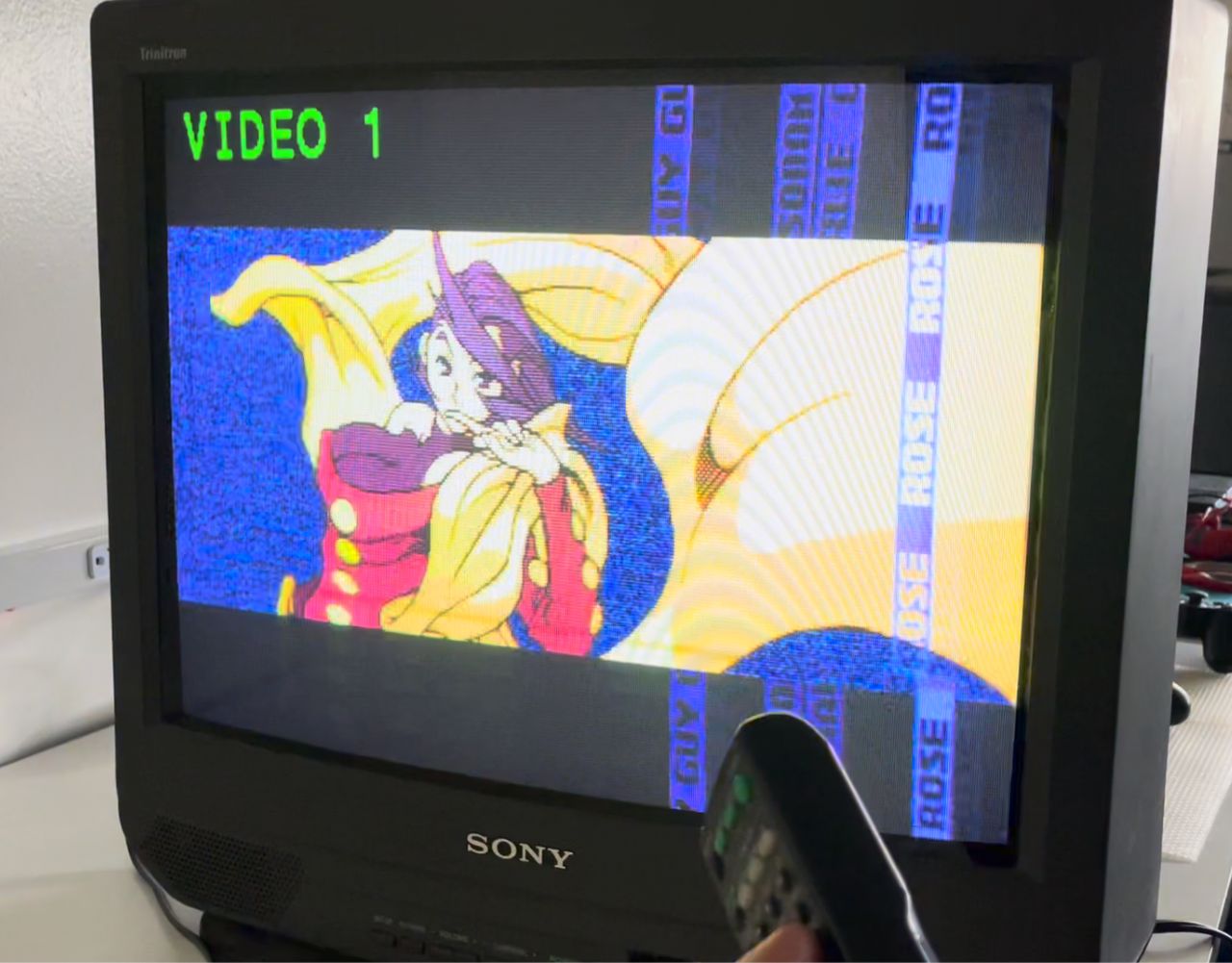
- RGB or Composite on Video1
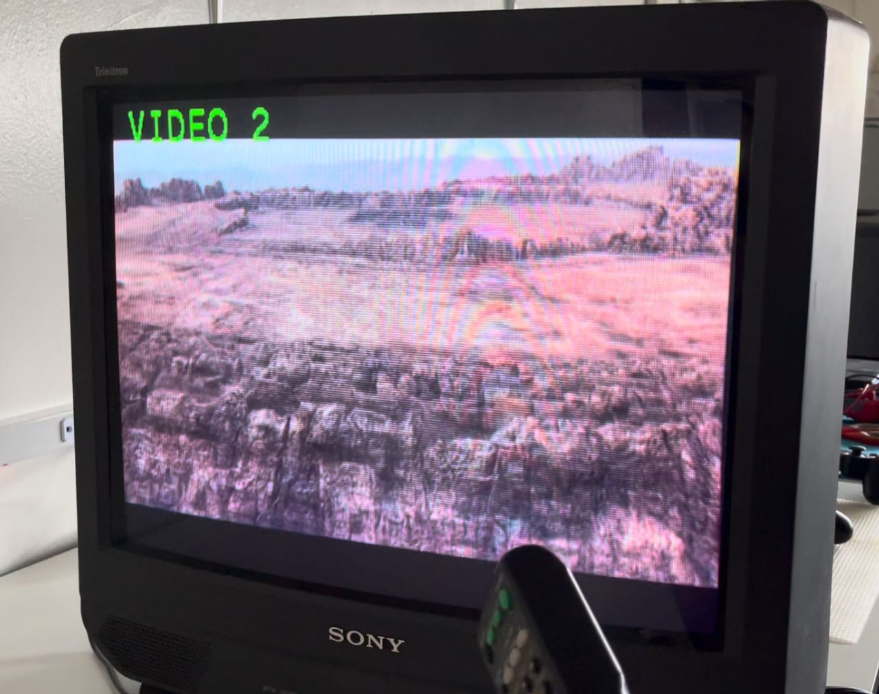
- Component on Video2
Let's get started!
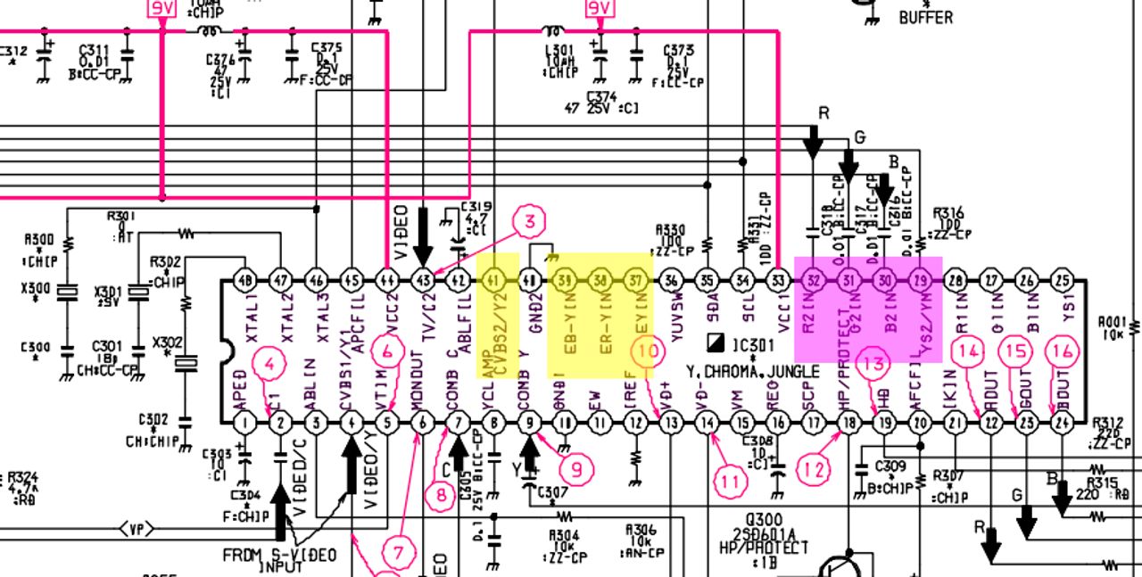
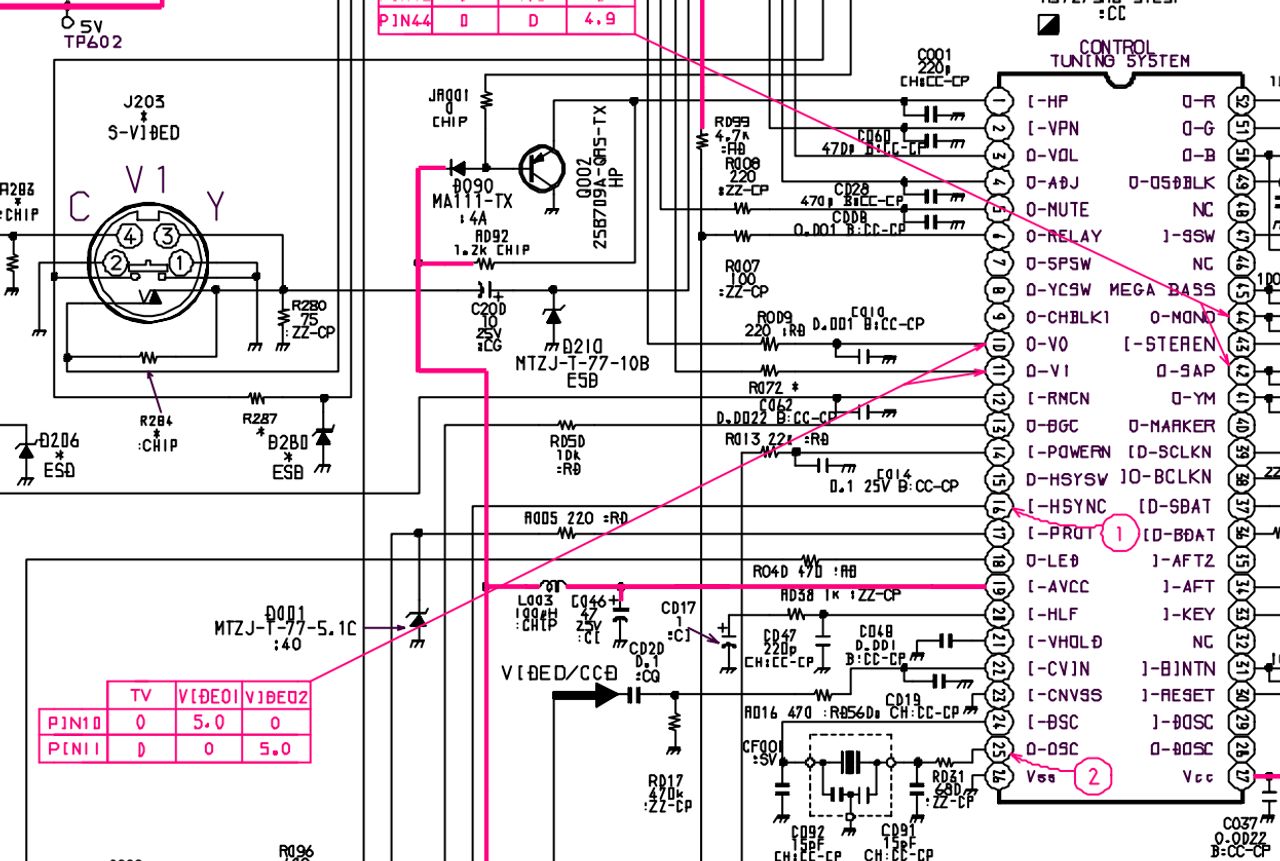
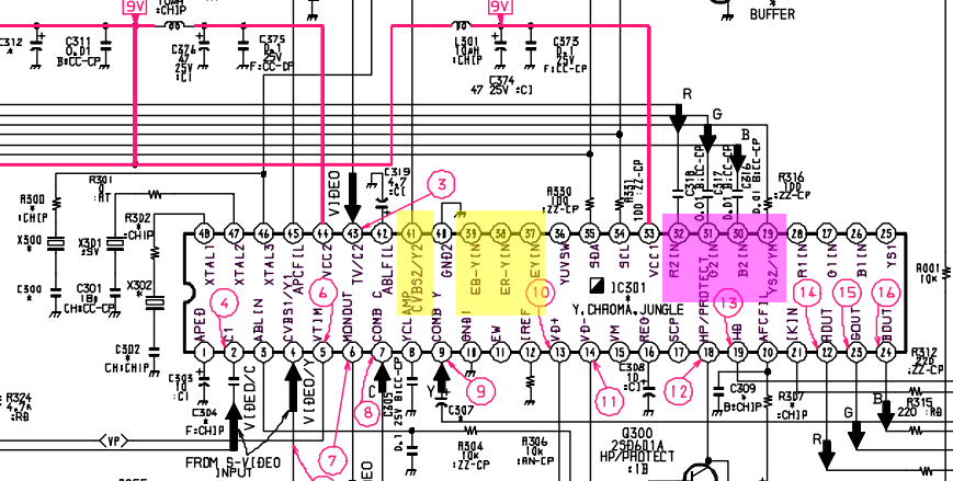 Looking at the Chroma/Jungle chip in the schematics, there are 2 sets of pins that are relevant:
- pins 32,31,30 will be used to inject the RGB signals, and pin 29 to switch to RGB mode. This chroma has an additional set of RGB inputs, but I decided to perform a RGB-mux mod, mainly for 2 reasons: 1) it is more convenient since R2/G2/B2 are exposed through jumper wires on the top of the chassi board, and 2) to use R1/G1/B1 I needed to either lift the pins or cut some traces and I wanted the mod to be reversible.
- pins 37,38,39 will be used to inject Y, Pr, Pb, and we will also need to use pin 41 for the sync signal and pin 36 to switch to component.
RGB mod
The RGB mod is fairly classical:
- Remove the grounding resistors R087, R088, R089
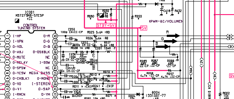
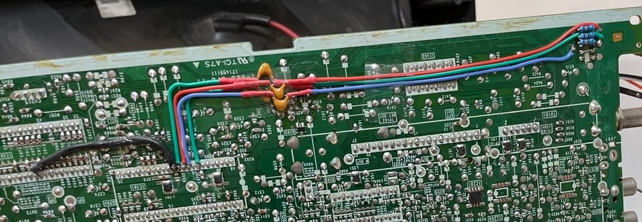
- Create a mux circuit with 75 Ohm termination resistors and 680 Ohm inline resistors for R, G, B, like shown in the picture.
 I used a custom small board I designed to simplify the work, since it's the same for all rgb-mux mods.
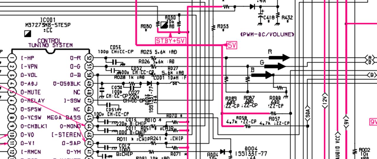
 - Connect the R,G,B signals to one leg of the resistors R025, R026, R027 and the blanking signal to one leg of L001.
 Get the 5V for blanking from one leg of R009, and ground from JW045.
Component YPbPr mod
Adding component on this set is also pretty easy:
- Terminate the Y, Pr, Pb signals to ground with 75 Ohm resistors and connect them to pins 37, 38, 39 through a 0.1 uF ceramic capacitor
- Connect the Y signal to pin 41 through a 0.1 uF capacitor, to pass the sync signal
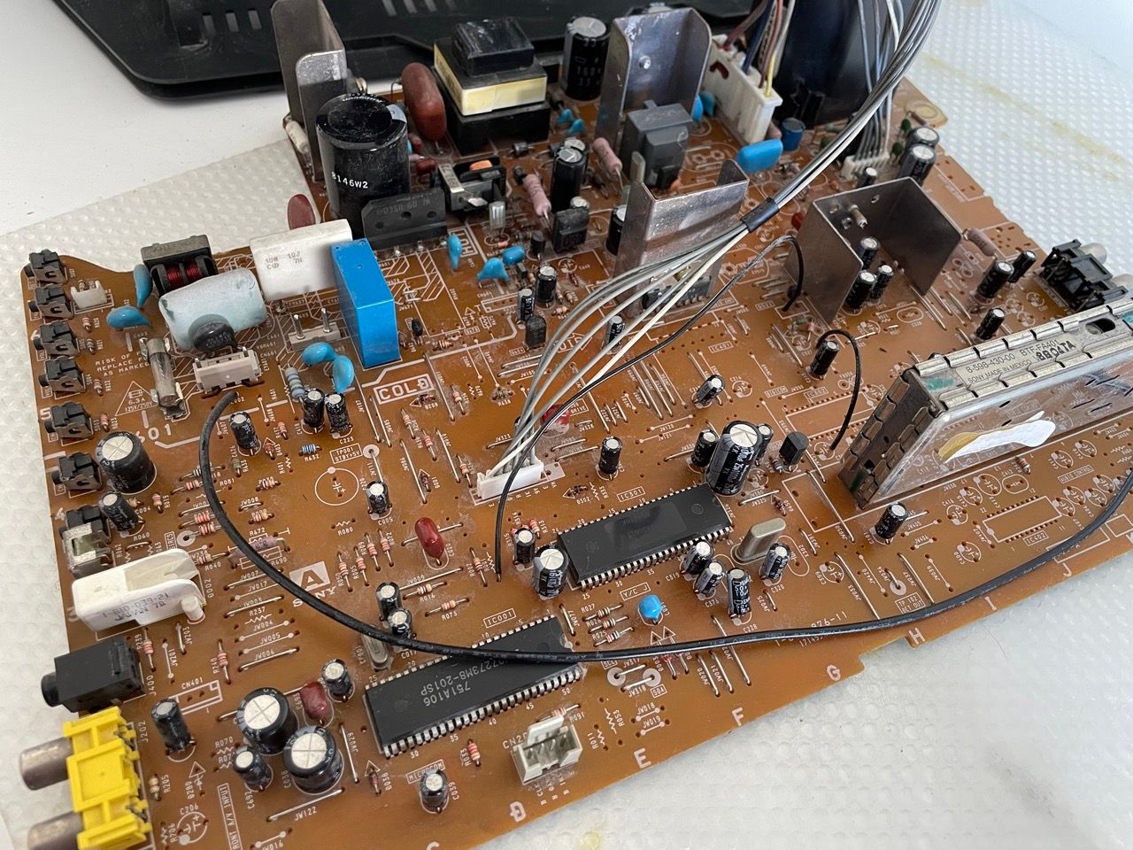
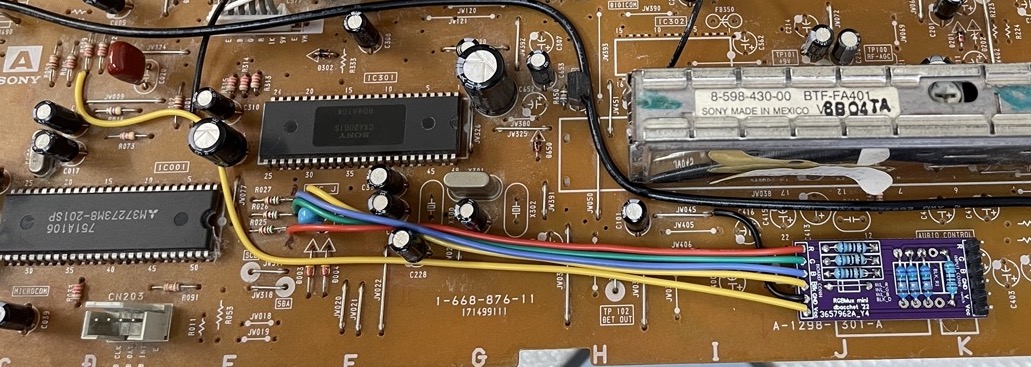
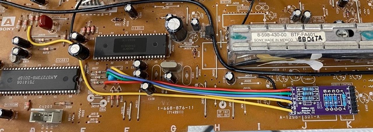
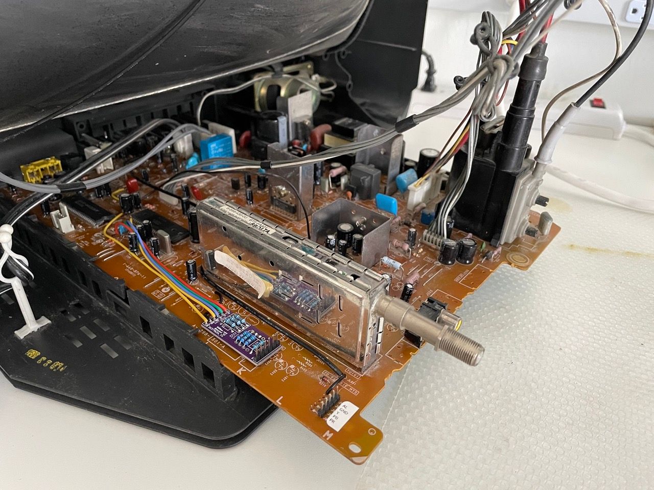
The result looks like the following picture: 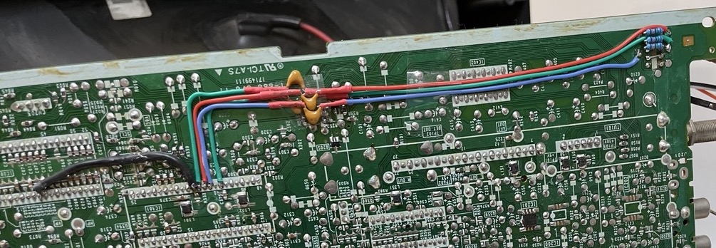 . There is an unpopulated header on the right that I used to bring the signals on the top of the chassis, for the grounding resistors and for the audio signal from Video2.
One thing worth mentioning here is that in my particular case I decided to disconnect the Video2 RCA (in the front of the tv) to be able to use that channel for component with the remote. In case you want to preserve that functionality (passing the sync on the original RCA connector and use a physical switch for enabling component) do not terminate the Y signal, since it's already terminated in the CVBS2/Y2 line. If you want to understand better why, this thread on shmups is a gold mine.
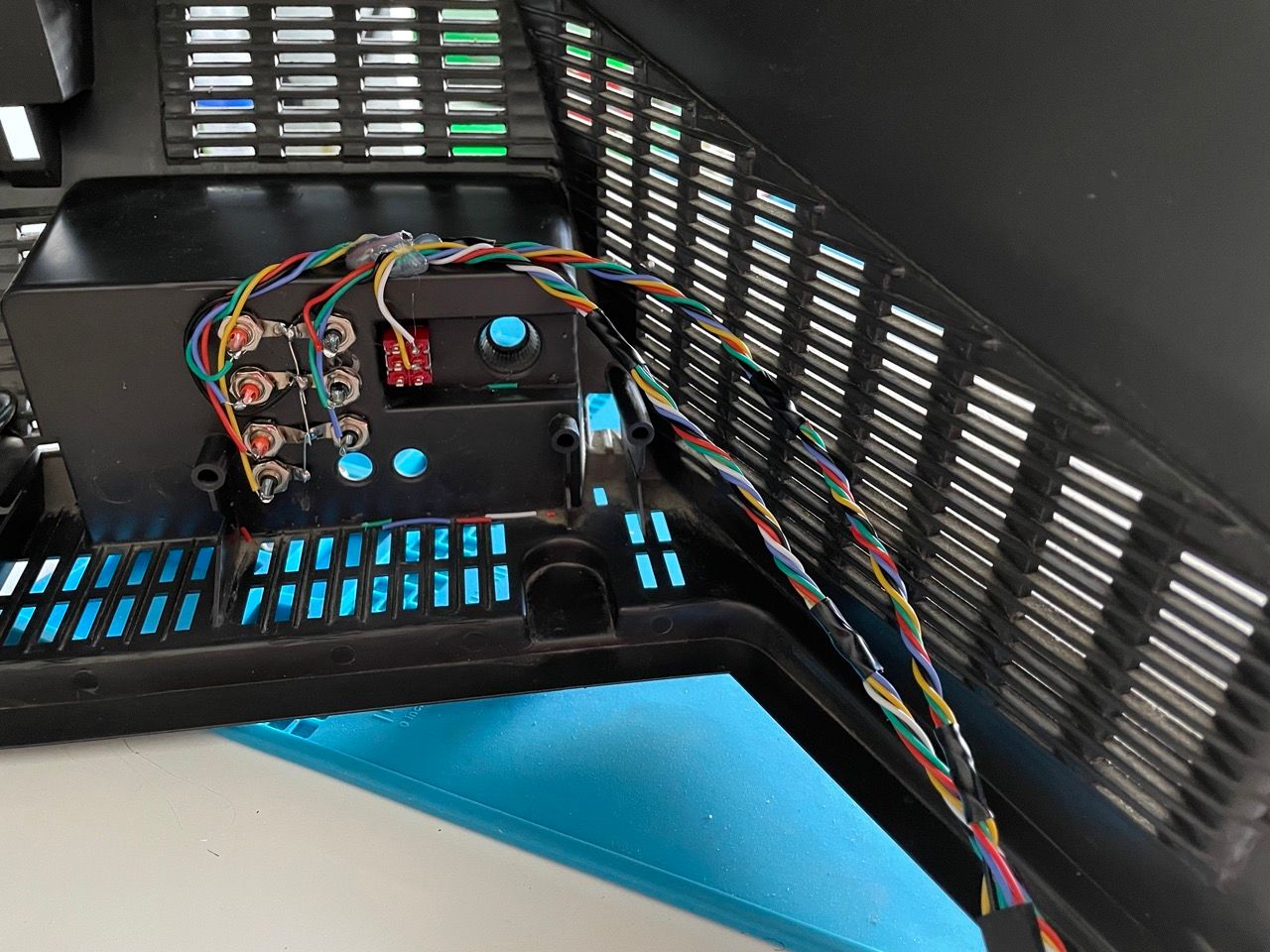
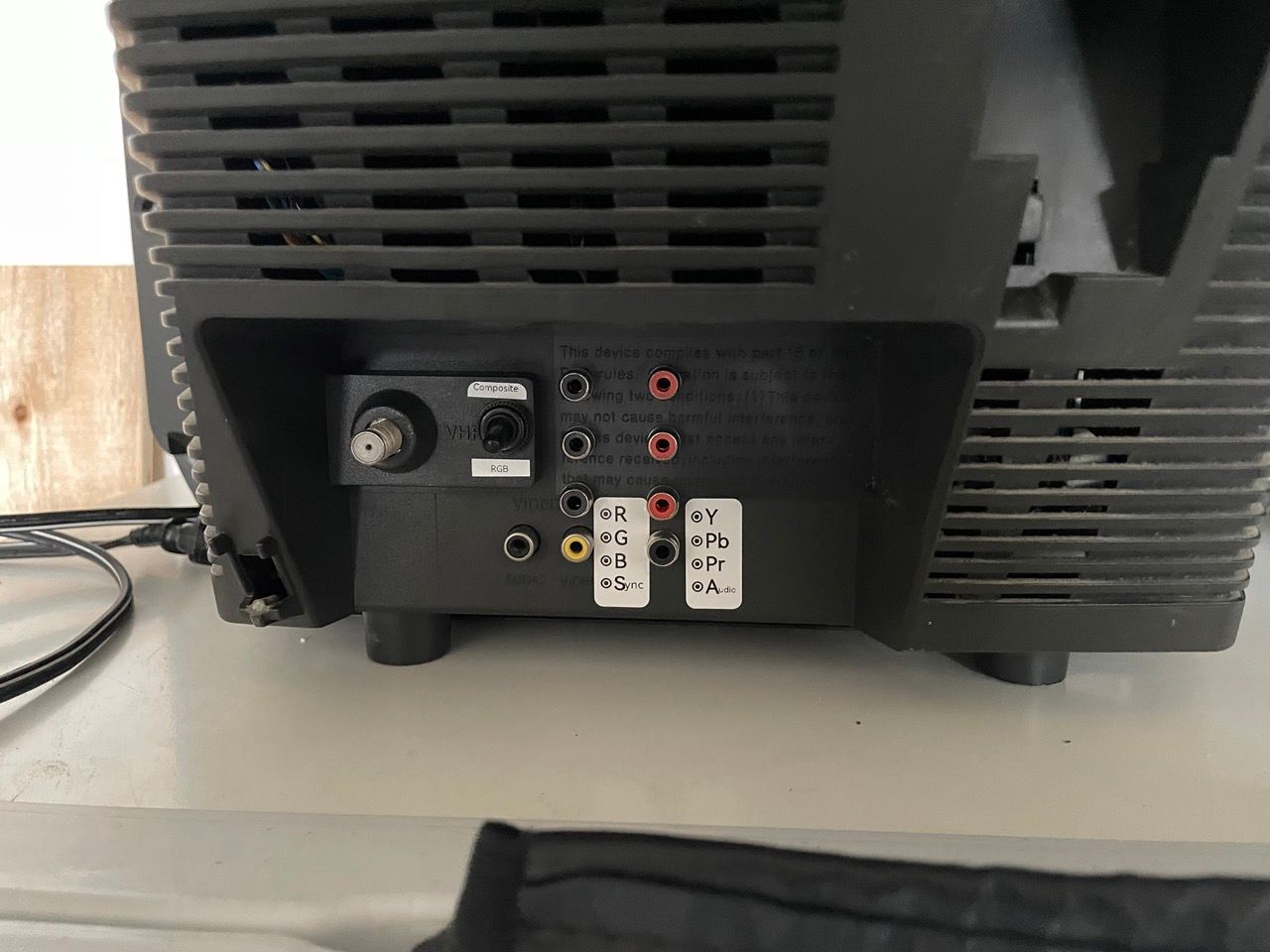
The final result looks like this: 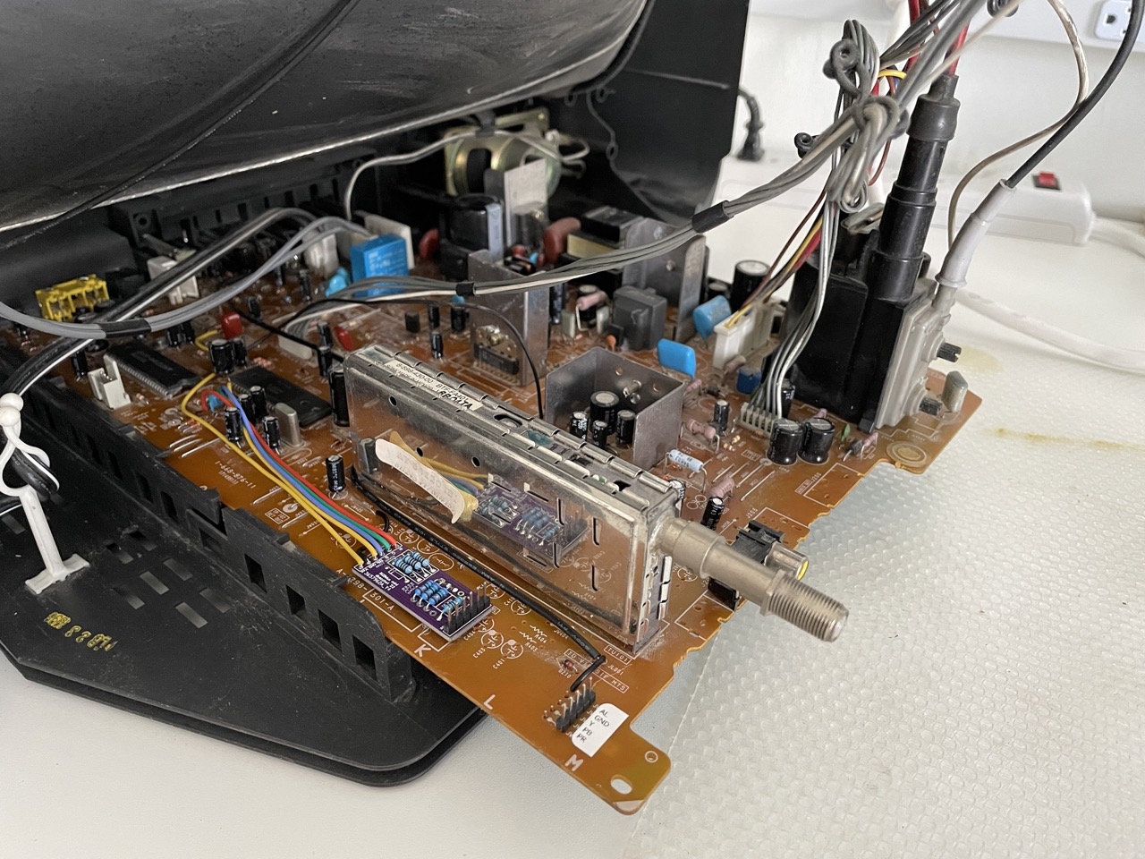 Note the pin headers for RGB (on the small PCB) and Component, that will be connected directly to the RCA connectors in the back of the TV:
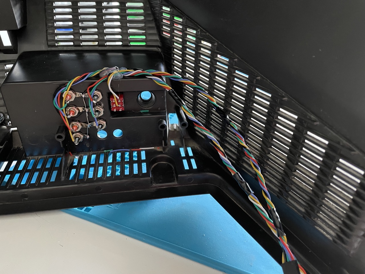
 The switch is used to commute between RGB and composite on Video1.
Using the remote to switch between TV, RGB and component YPbPr
This is the part of the mod that is a little more interesting. Instead of having a switch on the back that forces on RGB and/or Component on every channel, I wanted to be able to use the remote for selecting the input; so it's possible to keep all systems connected (i.e. a PS2 in component and a MiSTer in RGB) and just commute between them with the remote without having to get to the back of the TV every time.
On the BA4 chassis, the Micom has a very nice feature: pins 10 and 11 put out 5V when Video1 and Video2 are selected. So we can use them to enable RGB and Component by just tuning to the right input with the remote, how convenient! 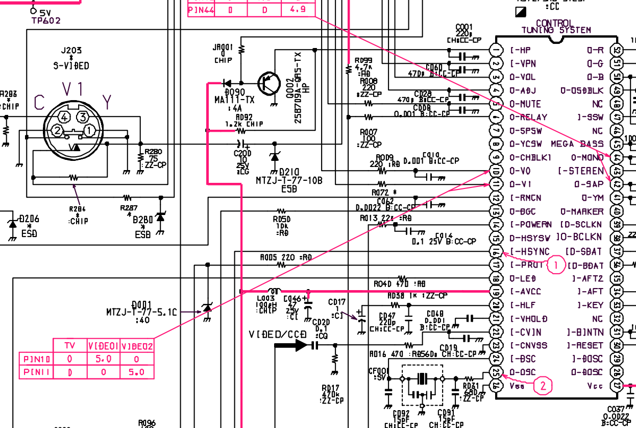 Probing the values it turs out that they produce 6.3V, and that is good because there is some margin to still have ~5V on those lines after we connect them to the RGB and Component switch pins in the chroma, since that will drain more current and slightly drop the voltage.
So what we need to do is:
- connect pin10 to pin 29 (YS2) in the chroma chip, through a 2.1K Ohm resistor. This will make the produced voltage drop from 6.3V to 5.1V, that is still within specs. I also used a switch to still be able to use composite, in this particular mod.
- connect pin11 to pin 36 (YUVSW) in the chroma, through a 2.1K Ohm resistor.
So now we can use the remote to switch! 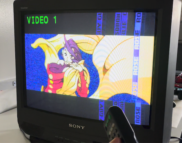
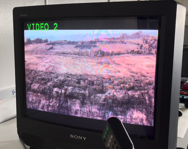
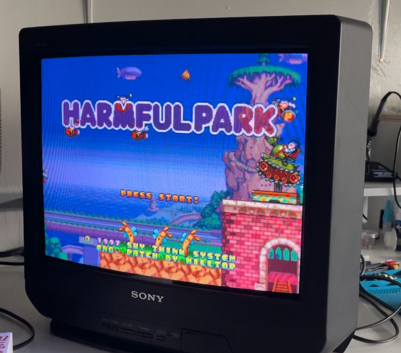
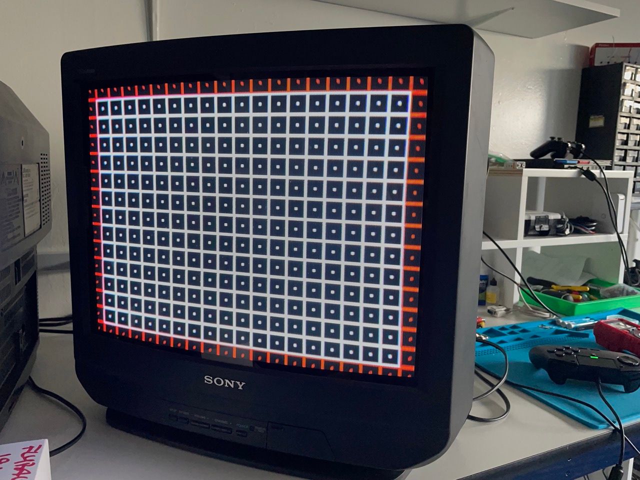
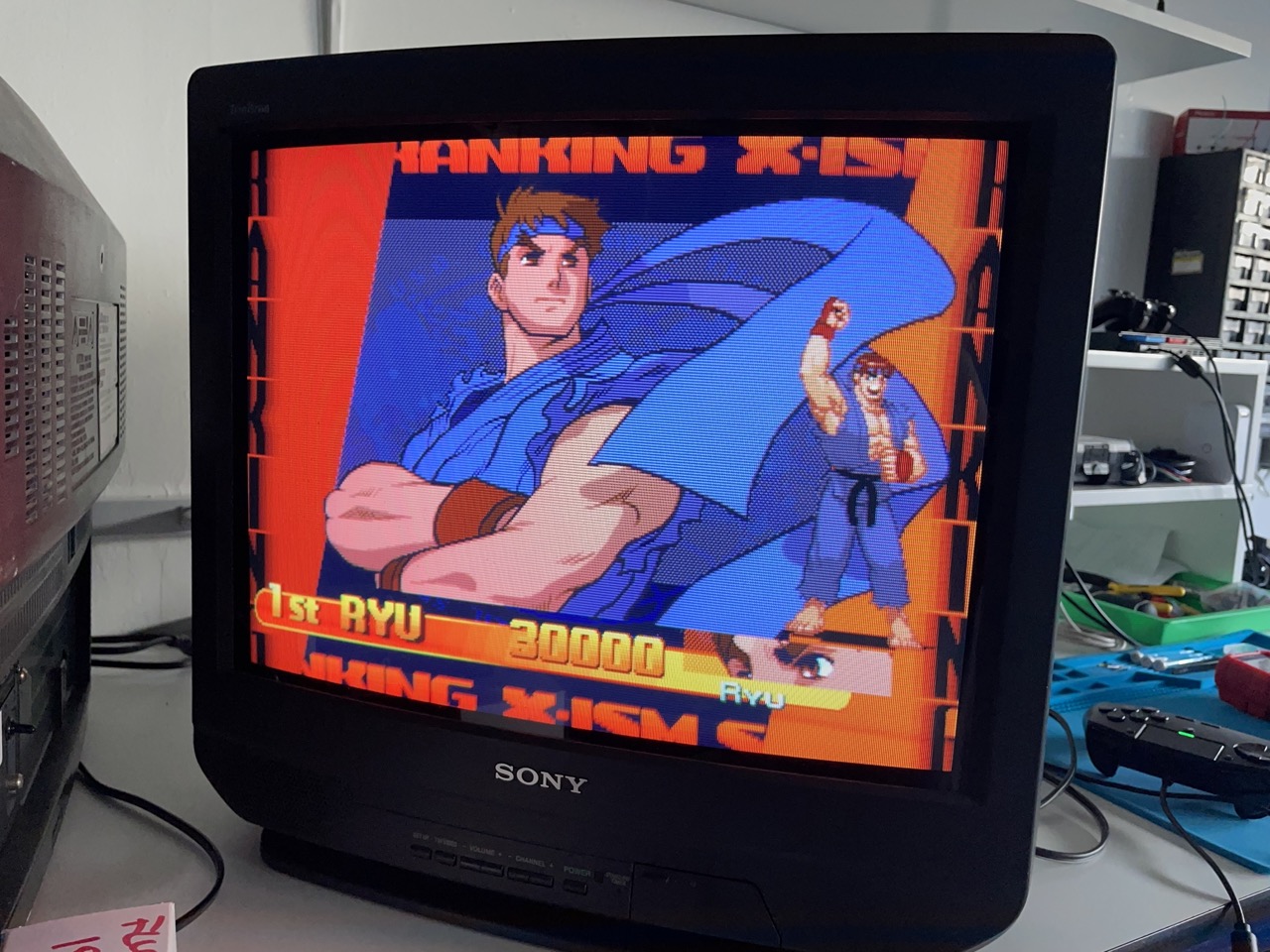
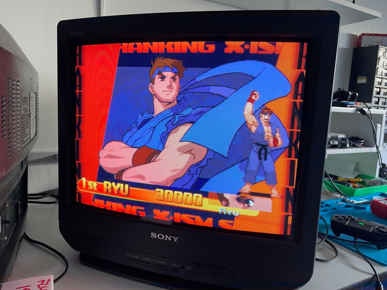
Quality is very good on both RGB and component, pretty happy on how it turned out!! 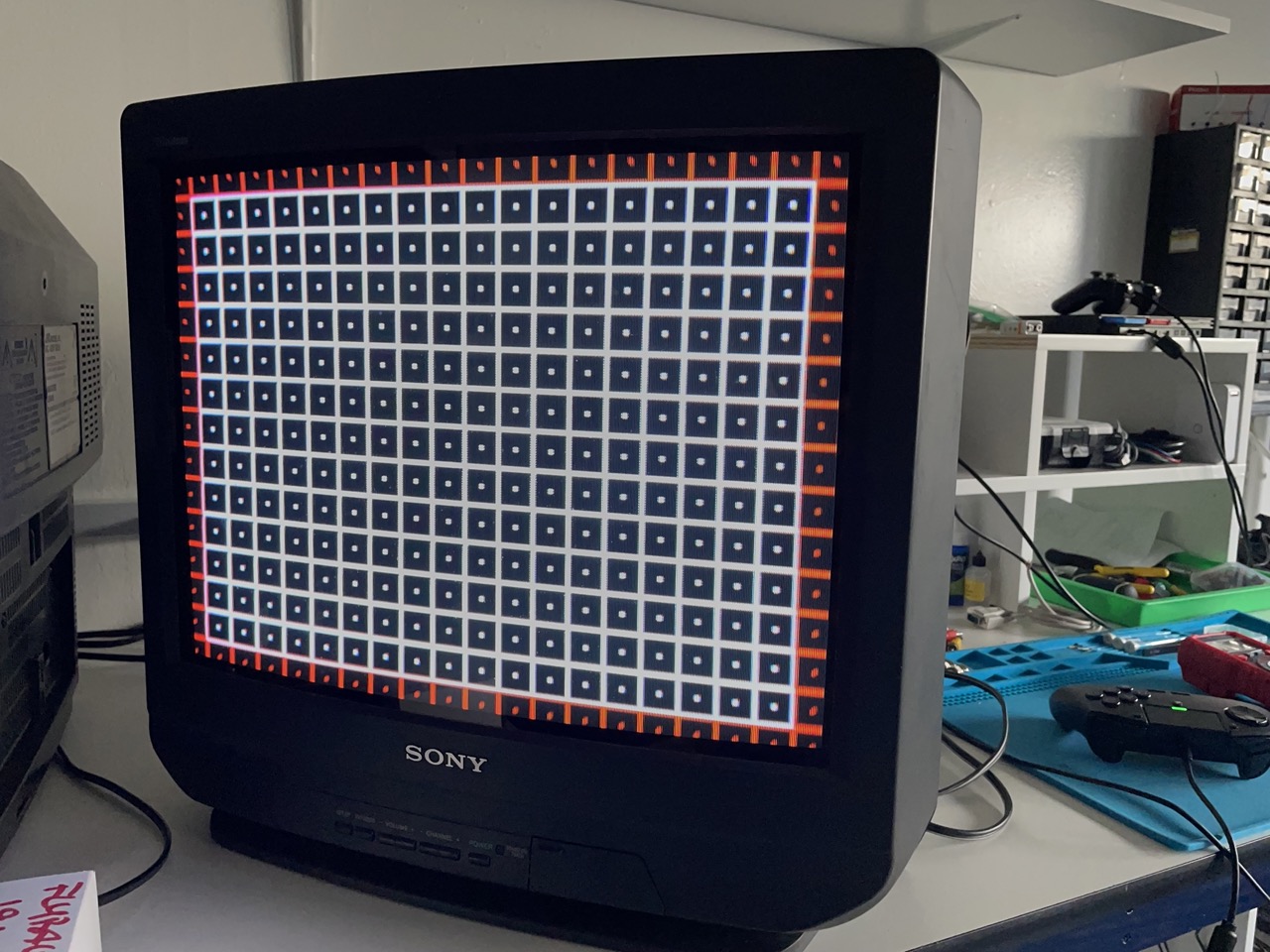


If you are using the Sunthar mux board, follow the below directions:
This mod uses the RGB mux board. This is optional, but will make your mod easier and stable. You can also create the circuit presented in the schematics above without the board. Please also checkout the mux calculator to play with your own values.
| On Sony CRT Chassis | KV-20M40 |
|---|---|
| CRT RGB inline resistor | 5.6kΩ |
| CRT RGB ground resistors removed | 680Ω |
| 0.1μF caps replaced | No |
| Add diodes on chassis RGB lines? | Yes |
| Add blanking diode on chassis | No |
| RGB mux board | KV-20M40 |
|---|---|
| Mux board RGB termination (R1, R2, R3) | 75Ω |
| Mux board RGB inline resistors (R4, R5, R6) | 1kΩ |
| Mux board Audio LR (R7, R8) | 1kΩ |
| Mux board blanking diode (R9) | 1N4148 |
| Mux board blanking ground resistor (R10) | open |
| Mux board blanking resistor (R11) | 1kΩ |
Compatible mux boards:
Pictures
Photos by Davide Bacchet
A friend brought me a very nice Sony Trinitron KV-20M40, that he wanted to mod. This set has a BA4 chassis that is very flexible so we decided to perform a dual mod, and add both RGB and Component support to this nice 20".


Reference Photos