External or SCART blanking
What blanking should I use?
I get asked this question a lot. I think it is time to put this in writing somewhere, so that this question can be answered for good 😃
What is blanking?
This is also known as fast blanking or YS. In layman terms, this is a digital switch to tell the chroma chip to display the R, G, B signal that is fed into it.
Slightly technical explanation.
Sending a 5V signal through the YS pin to the chroma (jungle) chip, blanks the other inputs and displays the external R, G, B signal that is fed into the chroma chip.
This method is then harnessed to do the R, G, B mux mod.
But, why a mux mod?
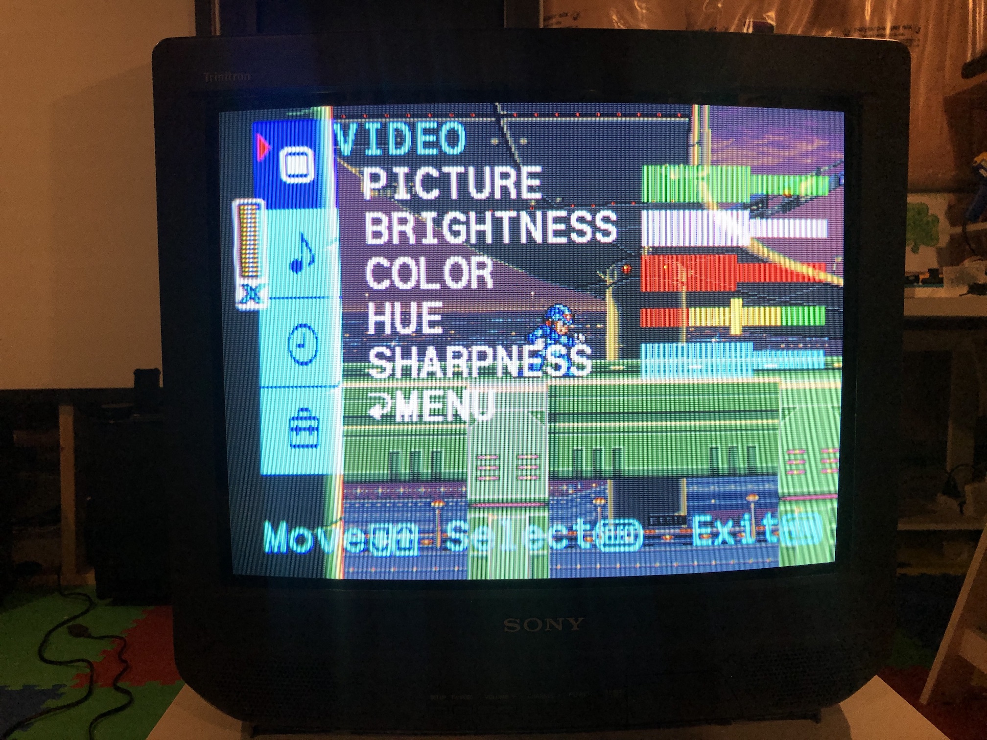
Do you want to see the OSD (on screen display) along with your RGB signal? Meaning, do you want to see the Menu options, Volume bars etc. layered on top of your RGB image? If you do, then you need to mux mod it. Therefore, you mux the blanking voltage along with the OSD. So, either one or both of those are able to ask the chroma chip to blank and display what is fed to it.
OSD overlay 
When is mux mod not needed?
There are CRTs that naturally have a second RGB input option available. Good example is Sony BA-1 chassis. For these CRTs, no muxing is needed, just feed the RGB signals to the second RGB input using the appropriate resistors and enjoy!
Where to source the 5V?
Before we answer this question, from usability perspective, below are the possibilities.
| Automatic switching | Manual switching | ||
| Mux mod with 5V from console | Mux mod with 5V sourced from the CRT | Traditional mod with 5V sourced from the CRT | |
| Pros | |||
| Cons | |||
For all the above scenarios, you have to be in the correct video input where your sync signal was fed into.
I highly recommend automatic switching. Less messy and straightforward to use. In case you need manual switching, you should go for Mux mod with 5V sourced from the CRT option. I would avoid Traditional mod with 5V from the CRT at all costs.
Considerations
FOR AUTOMATIC SWITCHING TO WORK
Make sure to source your SCART cables from reputable vendors. Make sure to double confirm you are only getting 5V from PIN 16 on your SCART cable. If the cable was mis-wired or you are using a modded console that outputs a voltage higher than 5V on PIN 16, then you can fry your chroma chip. That will be the end of your CRT. If you have a lower voltage on PIN 16 (like in the case of gscartsw), then blanking will not work. Check the below section on how you can get gscartsw to work!
Making gscartsw work with your auto switched mux mod
IS gscartsw WORTH IT?
I wouldn't suggest purchasing a gscartsw. It's very pricey, overhyped, and the long wait isn't worth it. I had to wait nearly six months after ordering, and honestly, it's not worth the hassle. While it might have been a decent option in the past, it's not anymore. There are much better and more affordable alternatives out there. For instance, I found a manual switch on AliExpress for about $75 including shipping, and I use it much more frequently. It's been working perfectly fine without any issues for the past two years. I can even shift my RGB image with it. There are so many auto and manual SCART switch options out there now, so do your research.
If you are a fan of not having any physical switches on your set, then you would be in for a surprise with the gscartsw. gscartsw forces 1.8V on pin 16 and 10V on pin 8, regardless of your input. At least this was the case with my particular version of gscartsw. Please confirm if your gscartsw behaves the same way.
1.8V won't effectively blank your RGB modified CRT since most Chroma ICs require a range of 2.5V to 5V for blanking. Here's a simple workaround to make gscartsw behave similarly to directly plugging in the SCART cable from the console to your RGB modified CRT TV.

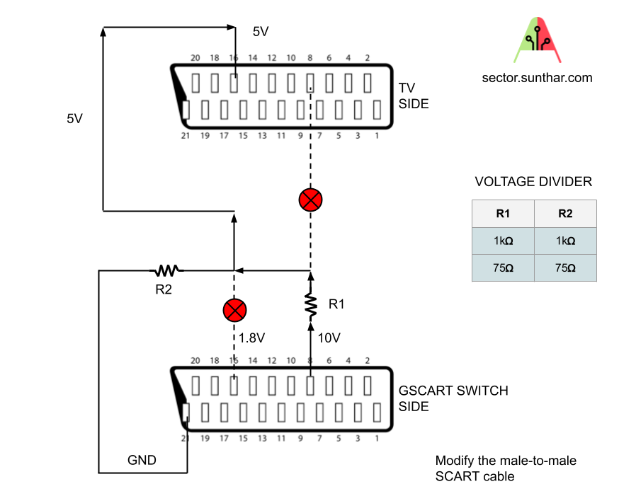
Essentially, we'll take the 10V from pin 8 and split it into 5V using two 1Kohm resistors. Then, we'll connect that to the pin 16 wire going to the output side. But remember not to connect it to pin 16 on the input side. Disconnect the wire from pin 16 on the input side and the wire from pin 8 on the output side, as illustrated in the diagram. You can also use other equal resistances (like 2x 75ohm resistors) to divide this voltage from 10V to 5V.
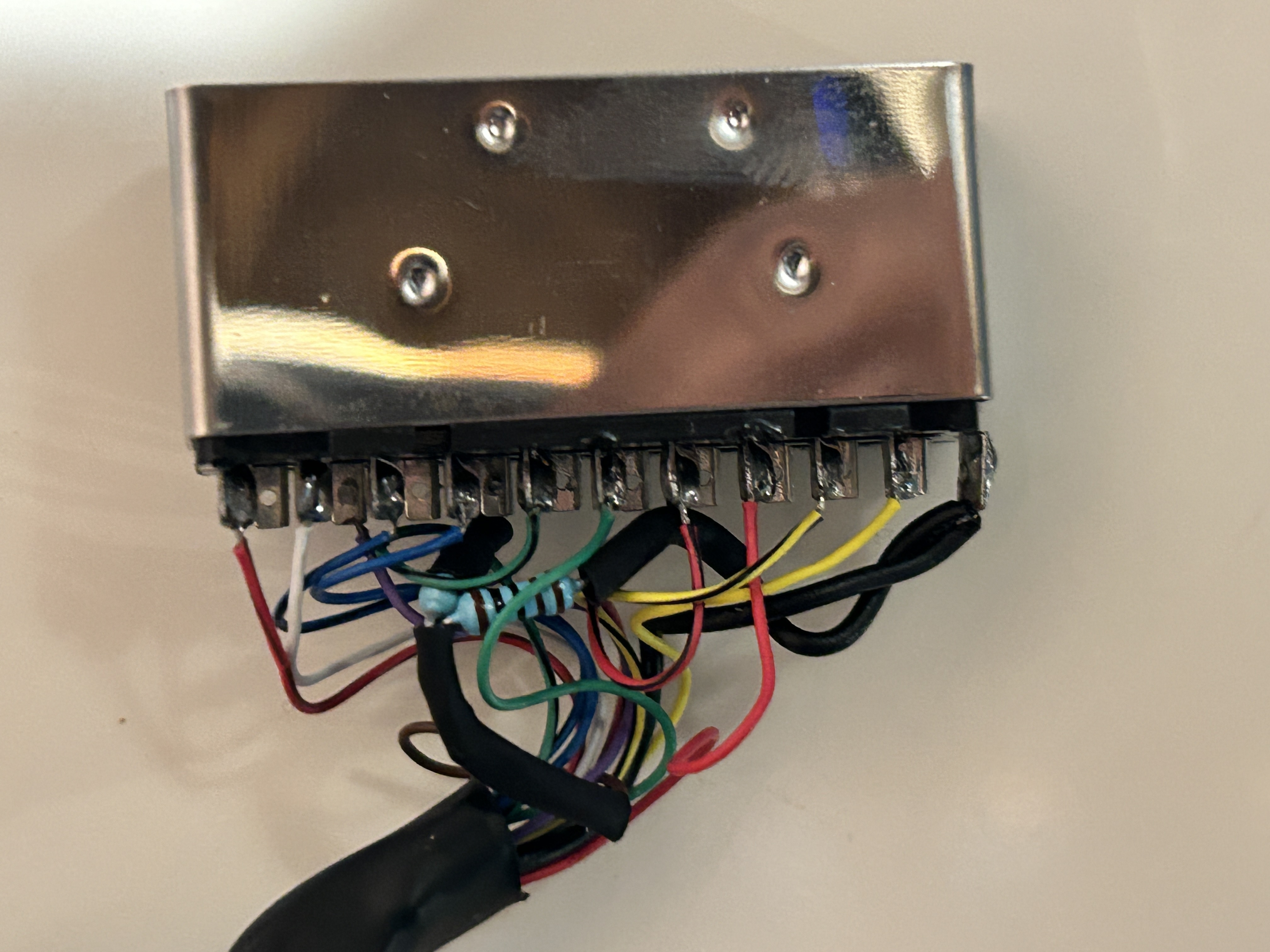
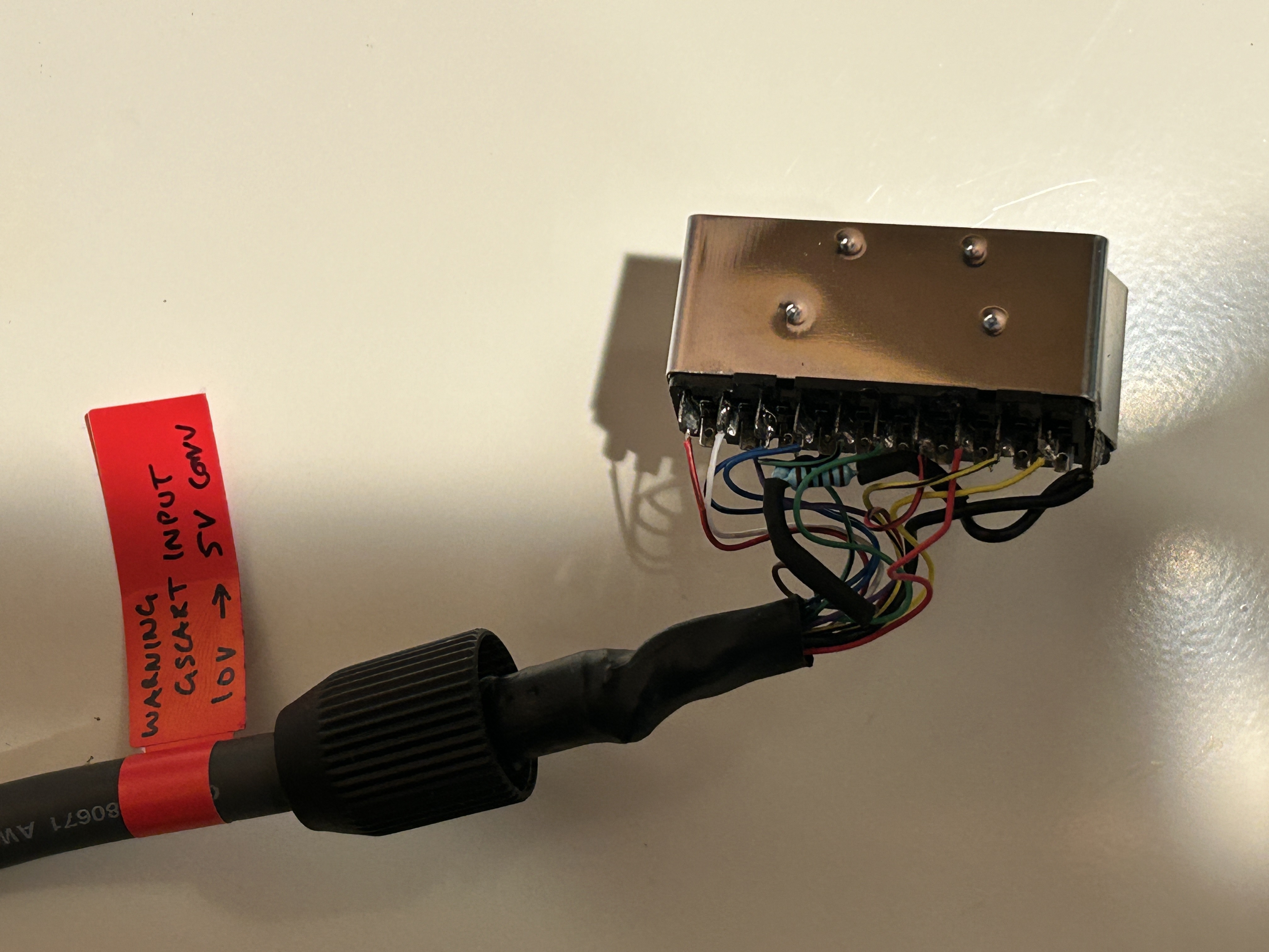
A picture speaks volumes. Although the following images might not offer a crystal-clear guide, they provide a general idea. You can observe how the two resistors are tied together on one end. This end should be linked to the pin 16 wire leading to the output side of the male cable. The remaining ends of the resistors are connected to pin 8 and ground, respectively. It's as straightforward as that. If this explanation isn't entirely clear, refer to the diagram provided earlier.

Be sure to label the cable to avoid plugging in the wrong end. Using the incorrect side won't cause any harm since we've already disconnected pin 16 from the input side and pin 8 from the output side.

