Samsung CXF0933
Samsung CXF0933 CRT RGB mod
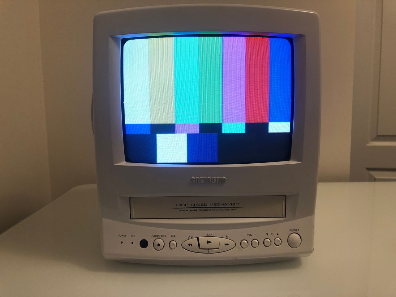
This is a beautiful 9" CRT. It's a combo unit and well built and really heavy for a 9" CRT. This CRT only supports mono audio. To select the AV input, you will need the original Samsung remote control.
View full CRT details and more mod examples →
This tutorial covers the RGB mod for the Samsung CXF0933 CRT TV.
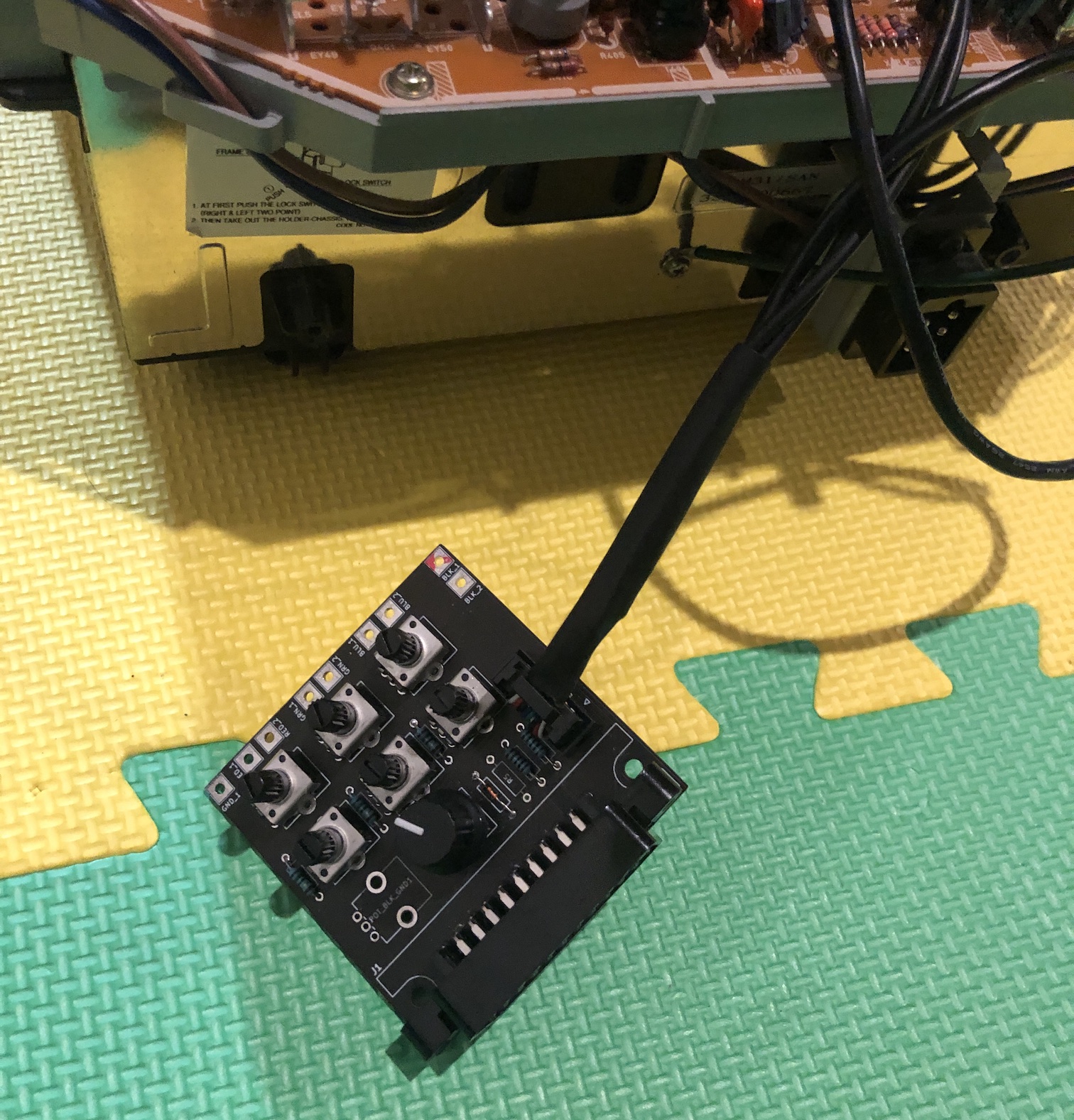
For smaller sets such as these, I decided to use a custom micro RGB board with XRGB-mini (8 pin input).
Contributors
Thank you to everyone who contributed to this guide:
- Sunthar — contributor, RGB mod tutorial
CRT safety
Caution
You can die doing this! So read carefully! CRT TV is not a toy. Do not open a CRT TV. If you don't have any prior knowledge about handling high voltage devices, this guide is not for you. CRT TV contains high enough voltage (20,000+ V) and current to be deadly, even when it is turned off.
Plan of attack
Manuals and Datasheets
- Toshiba TA1201AN Datasheet (Jungle) — Available for Pro Users only. See CRT details for access.
Specs
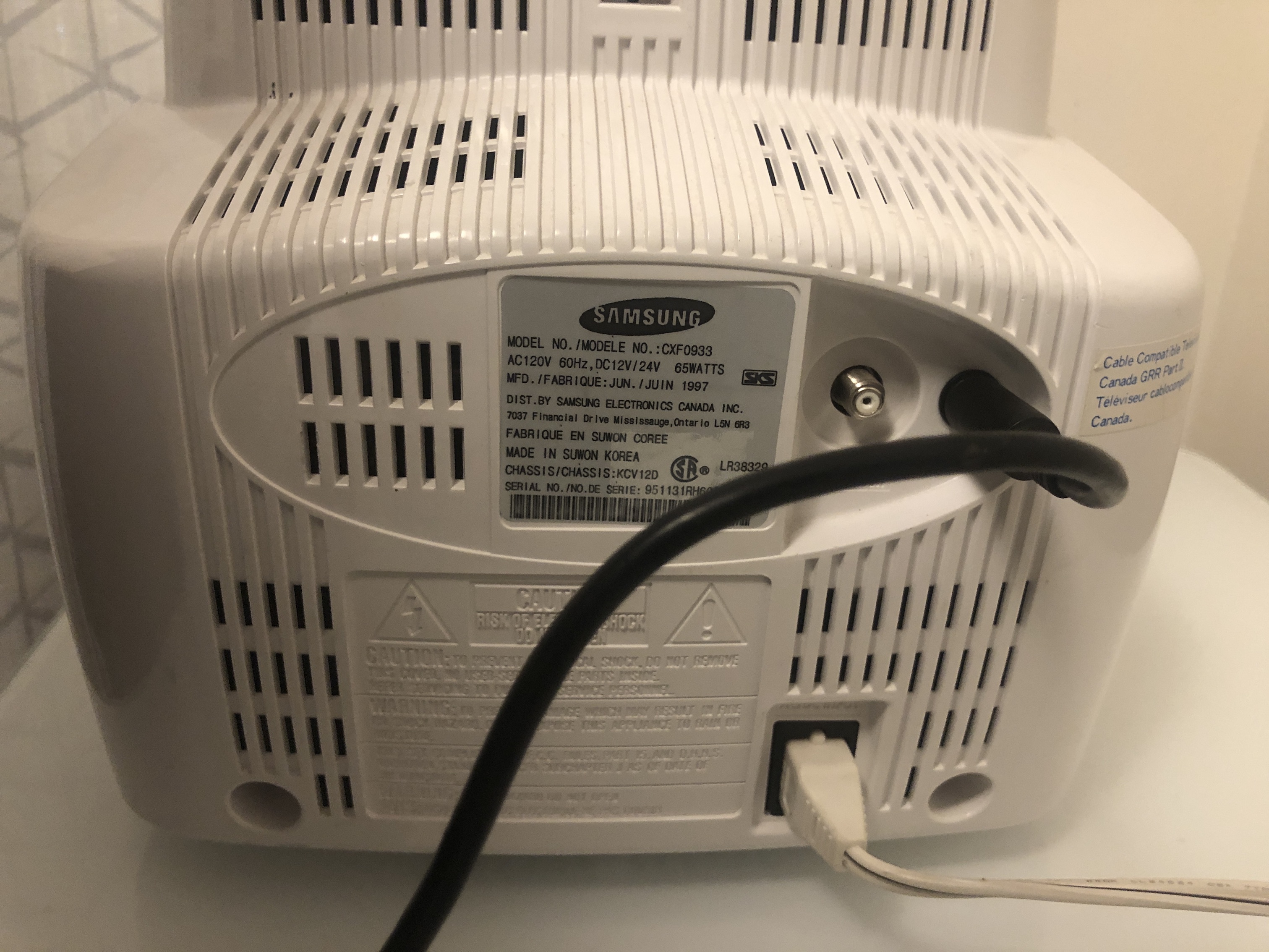
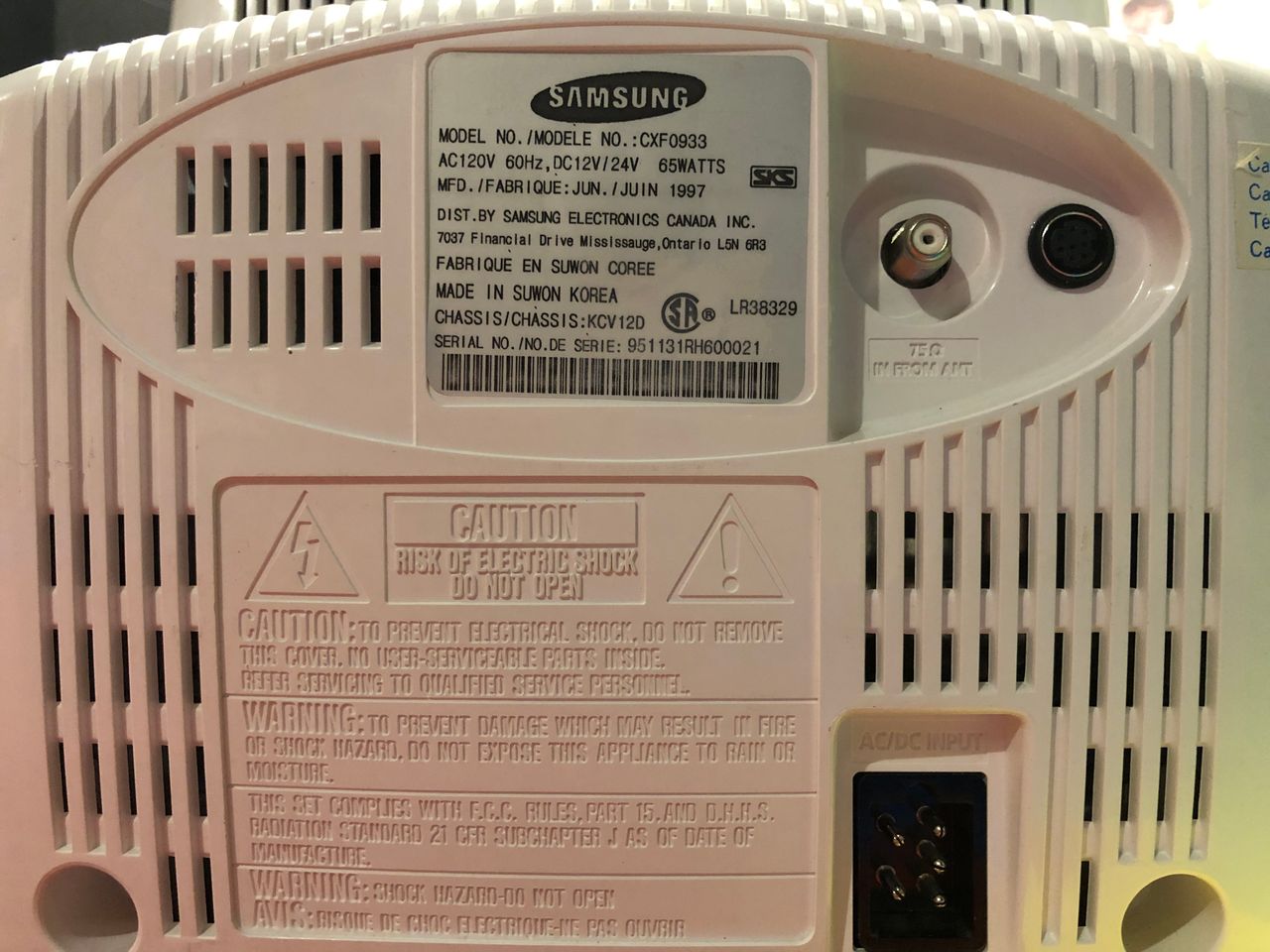
- Manufactured: Korea (1997)
- Chassis: KCV12D
- Tube: A23KQU22X01
- Jungle Chip: Toshiba TA1201AN
- OSD Chip: ZiLOG Z8933212PSC
- Screen Size: 9"
Samsung CXF0933 Schematics (KCV12D) 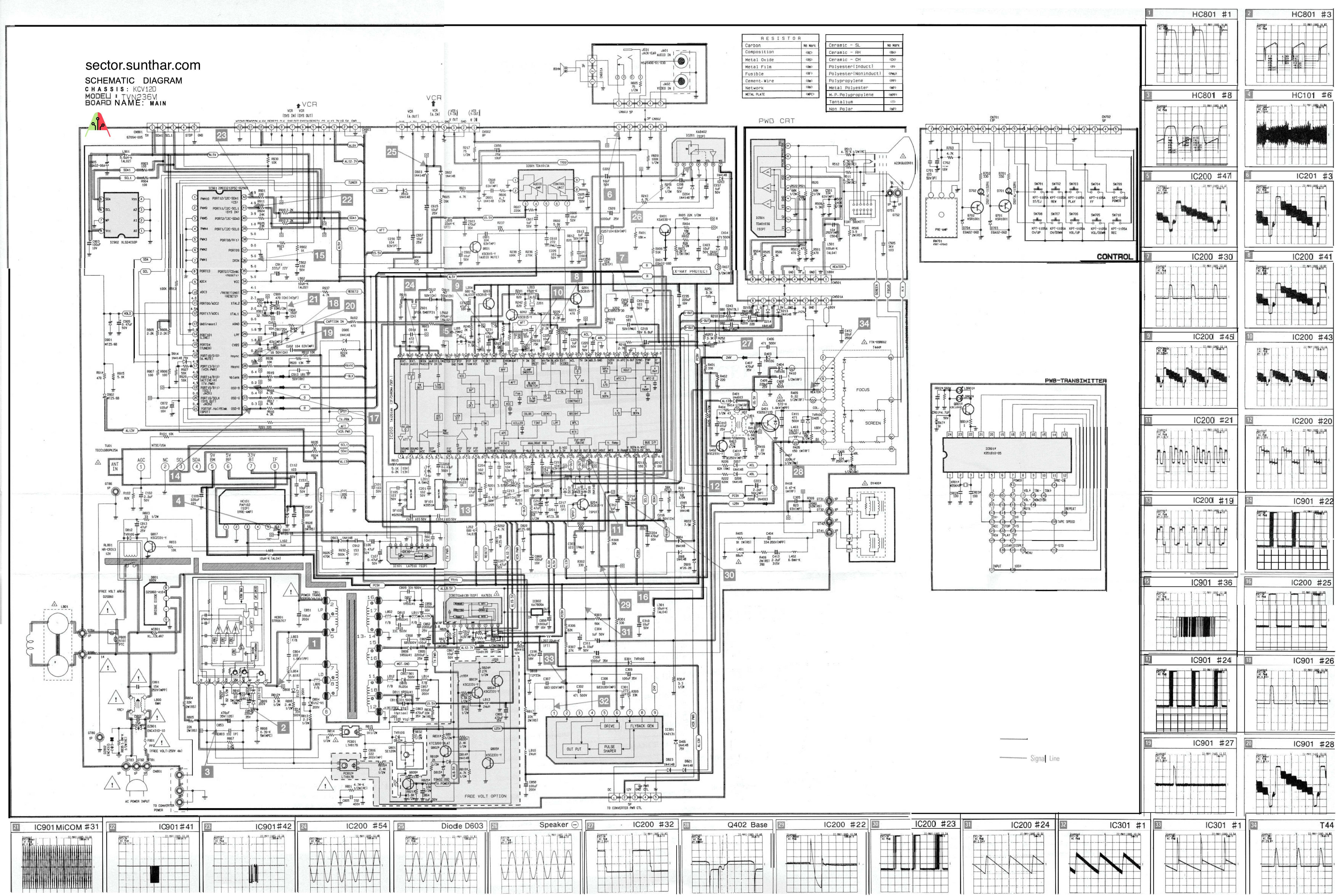
Prototyping the mod
I reviewed the schematics and came up with the below plan.
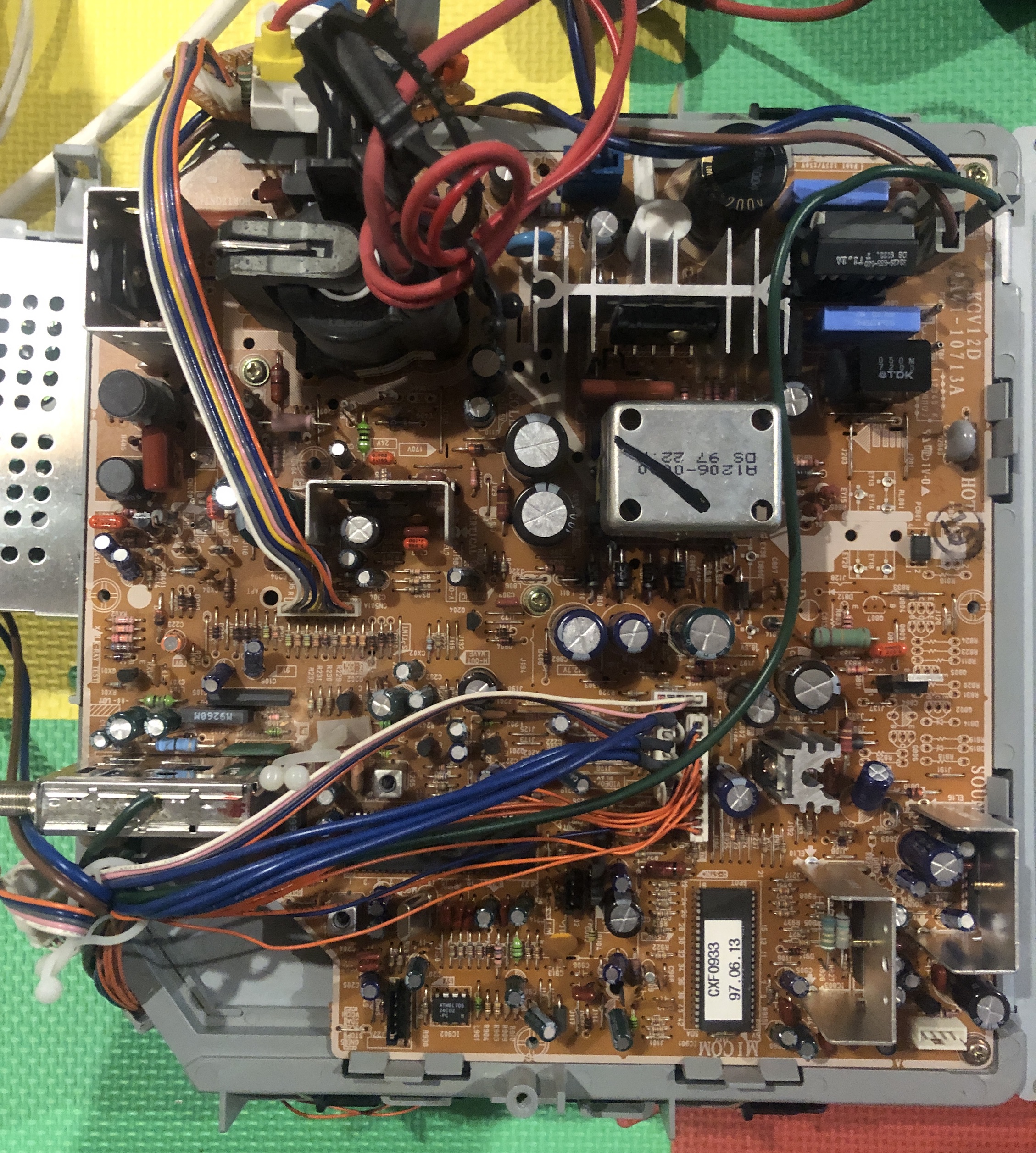
This is a VCR/CRT combo unit. However, great news is that the main board is fairly compact and comes off the CRT completely, if all the wires are carefully disconnected. This makes it easier to perform the mod. Please make sure to remember or take photos as you disassemble, so that you can reassemble the way it was prior to disassembly. Turning on the CRT with disconnected wires can result in shorted components.
Simplified circuit diagram that was created to perform this mod. Check the RGB theory page to find more details around how to calculate the resistor values.
RGB mux diagram
Prepare the mux diagram. If you are building your own circuit, this diagram should help.
Increasing RGB termination resistance
This CRT uses a Toshiba chroma chip that benefits from increased RGB termination resistance. Using 220Ω instead of 75Ω gives the right level of contrast and brightness. This made a significant difference in image quality. Image went from slightly darker, washed out to a vibrant desirable image. This fix applies to the following Toshiba jungle chips. Might also work for other jungle chips, where the RGB signals go through only RGB cutoff block.
- Toshiba TA1201AN
- Toshiba TA1286N
- Toshbia TA1242N
I also made an apparatus to sweep through multiple termination values. 220Ω termination seems to give the best result.
Performing the mod
This CRT was fairly straightforward to mod.
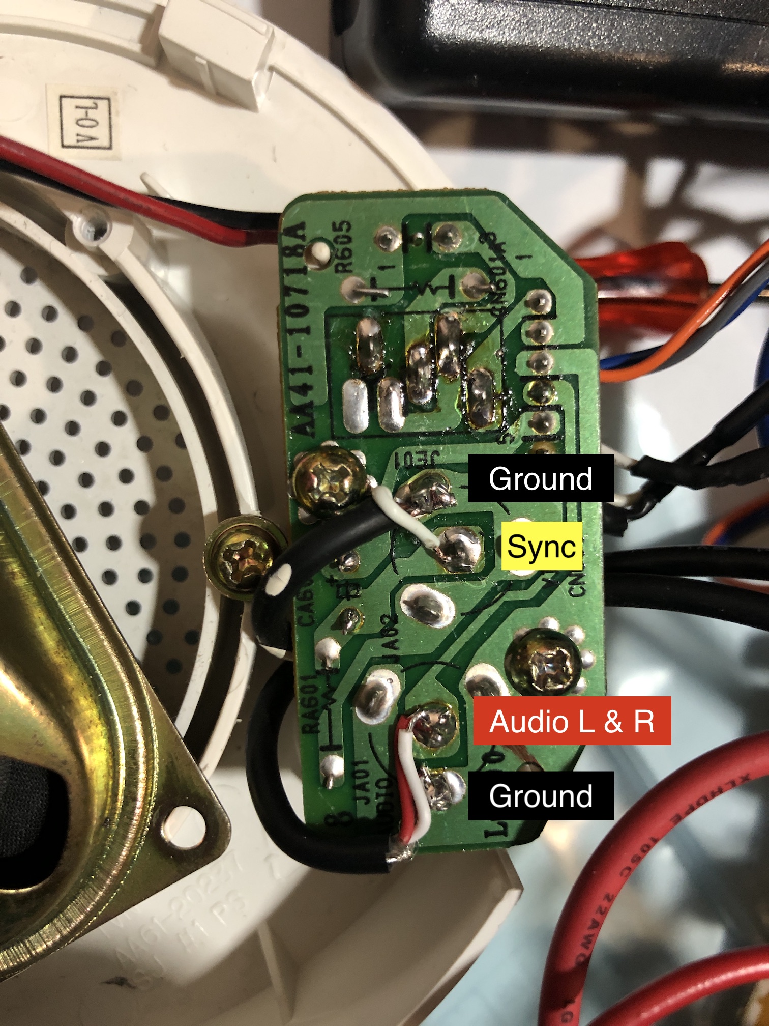
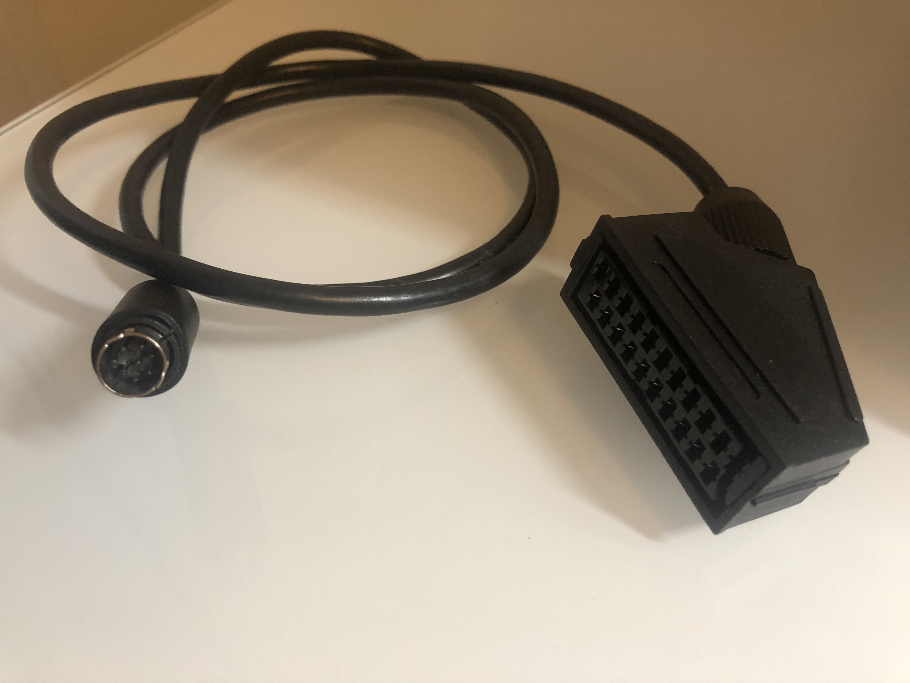
STEP 1: Audio and sync wires
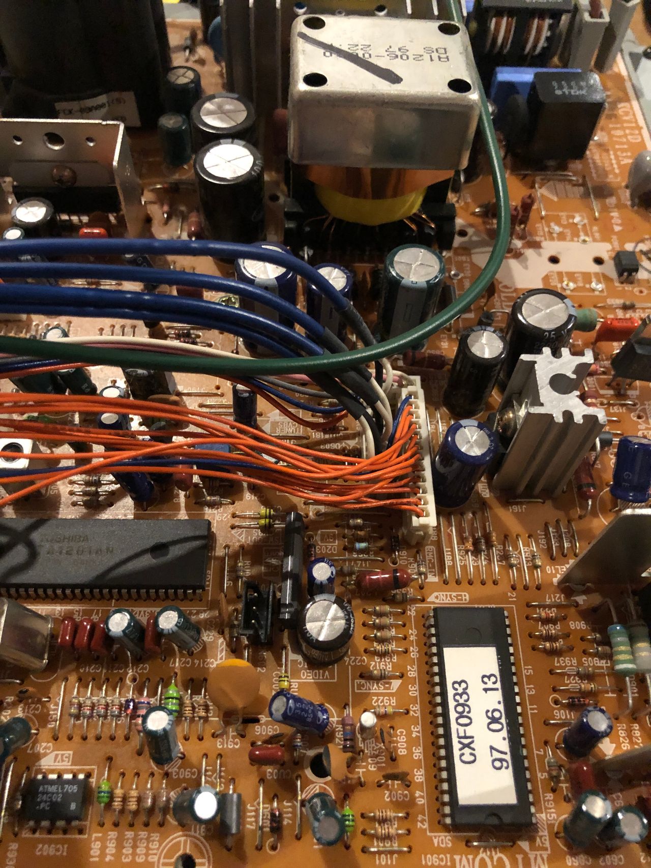
STEP 2: Remove components
- Remove R204, R205 and R206 resistors. These should be 820Ω resistors.
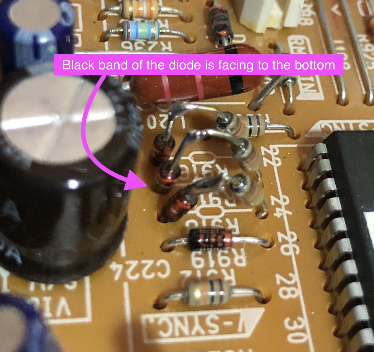
STEP 3: Add diodes
- Replace 56Ω resistor with 1N4148 diode (pay attention to the direction)
- Add 3x 1N4148 diodes to R916, R917 and R918 (4.3kΩ) (see pictures below and schematics above)
- Remove R919 and add a diode instead. This is for blanking.
STEP 4: RGB and blanking wires
Holes left from removing the R204, R205 and R206 resistors can be used here. Before mod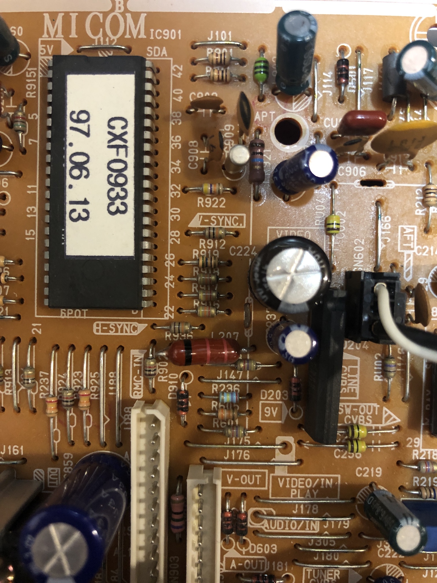
After mod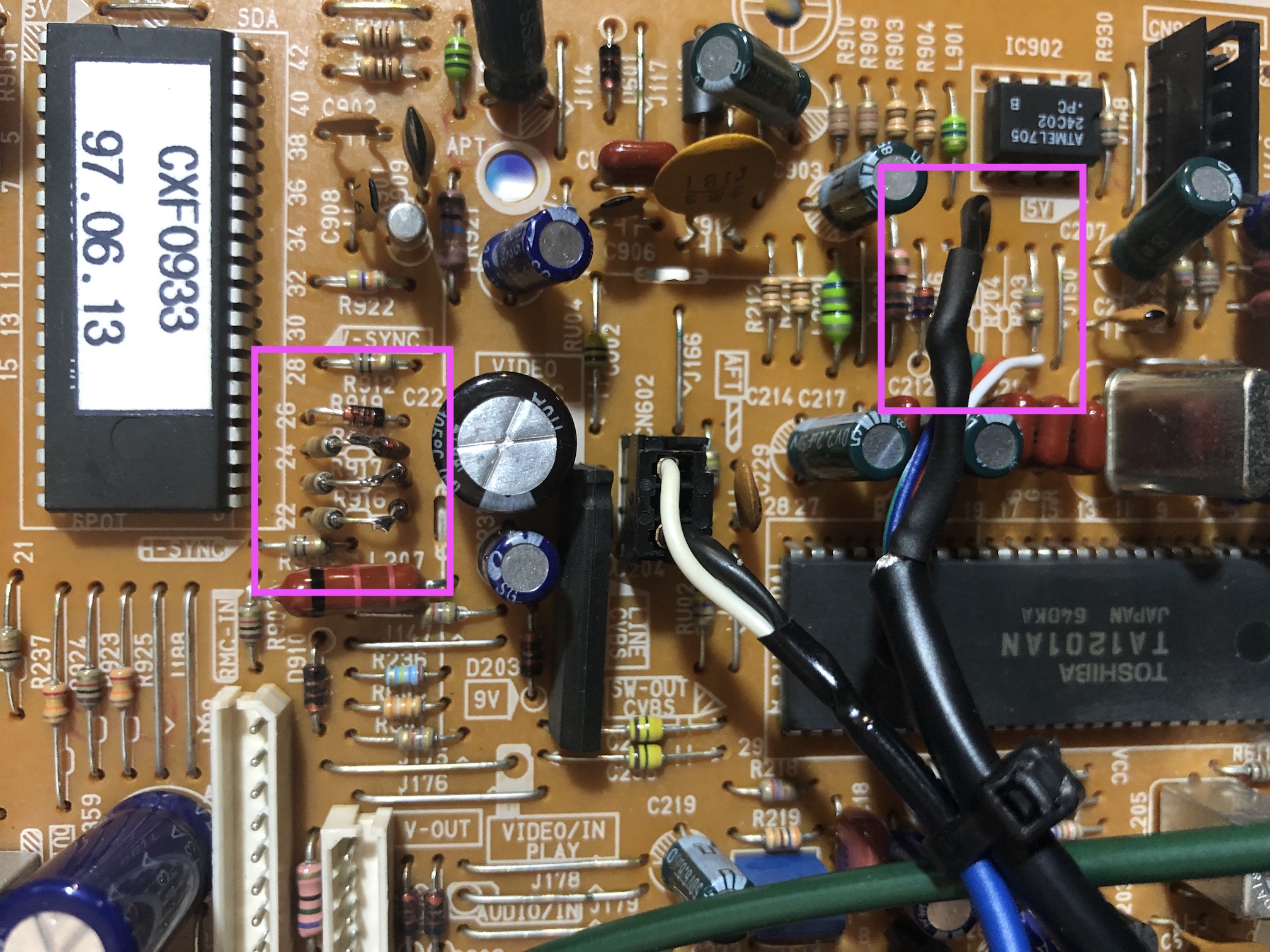
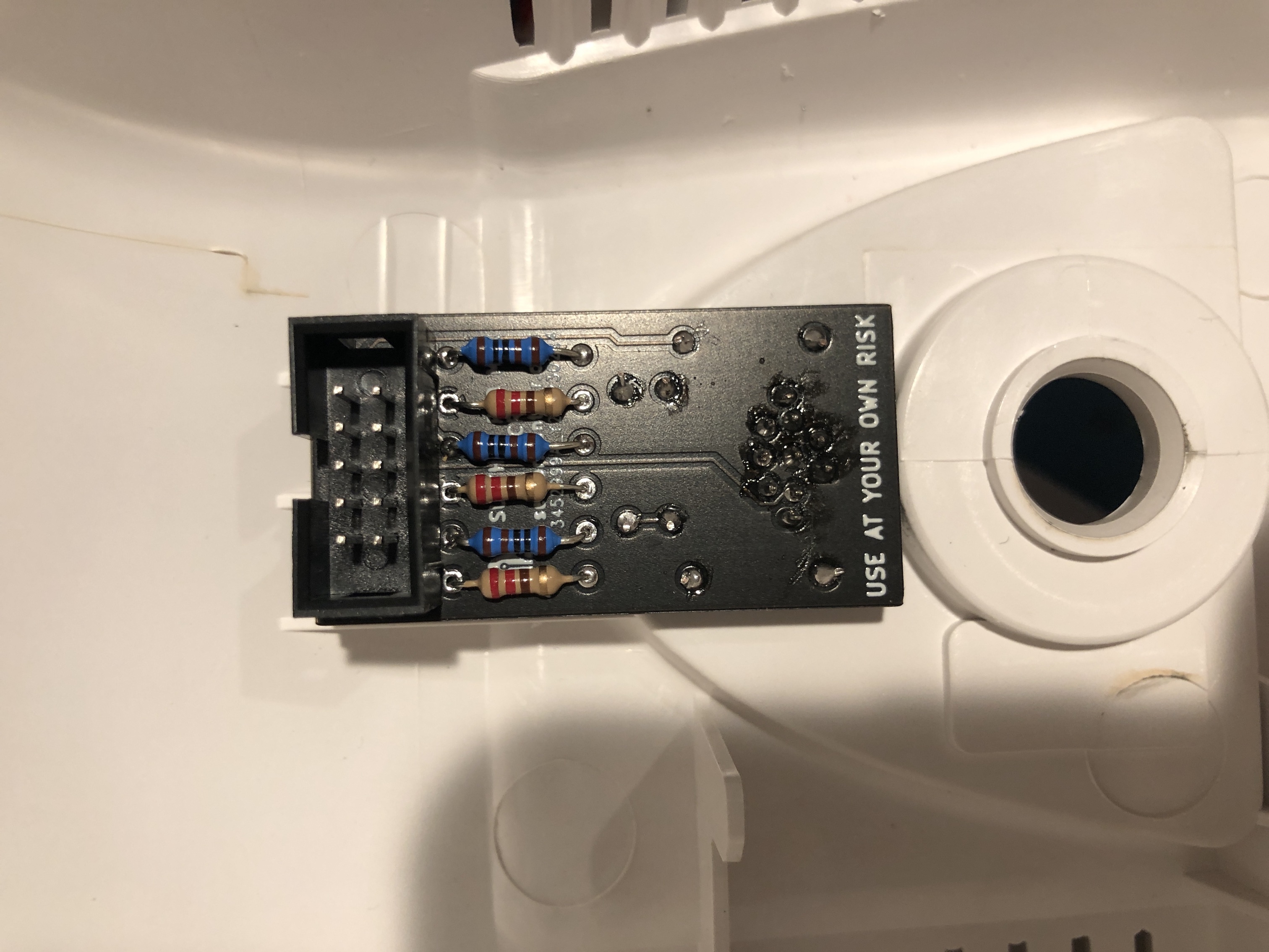
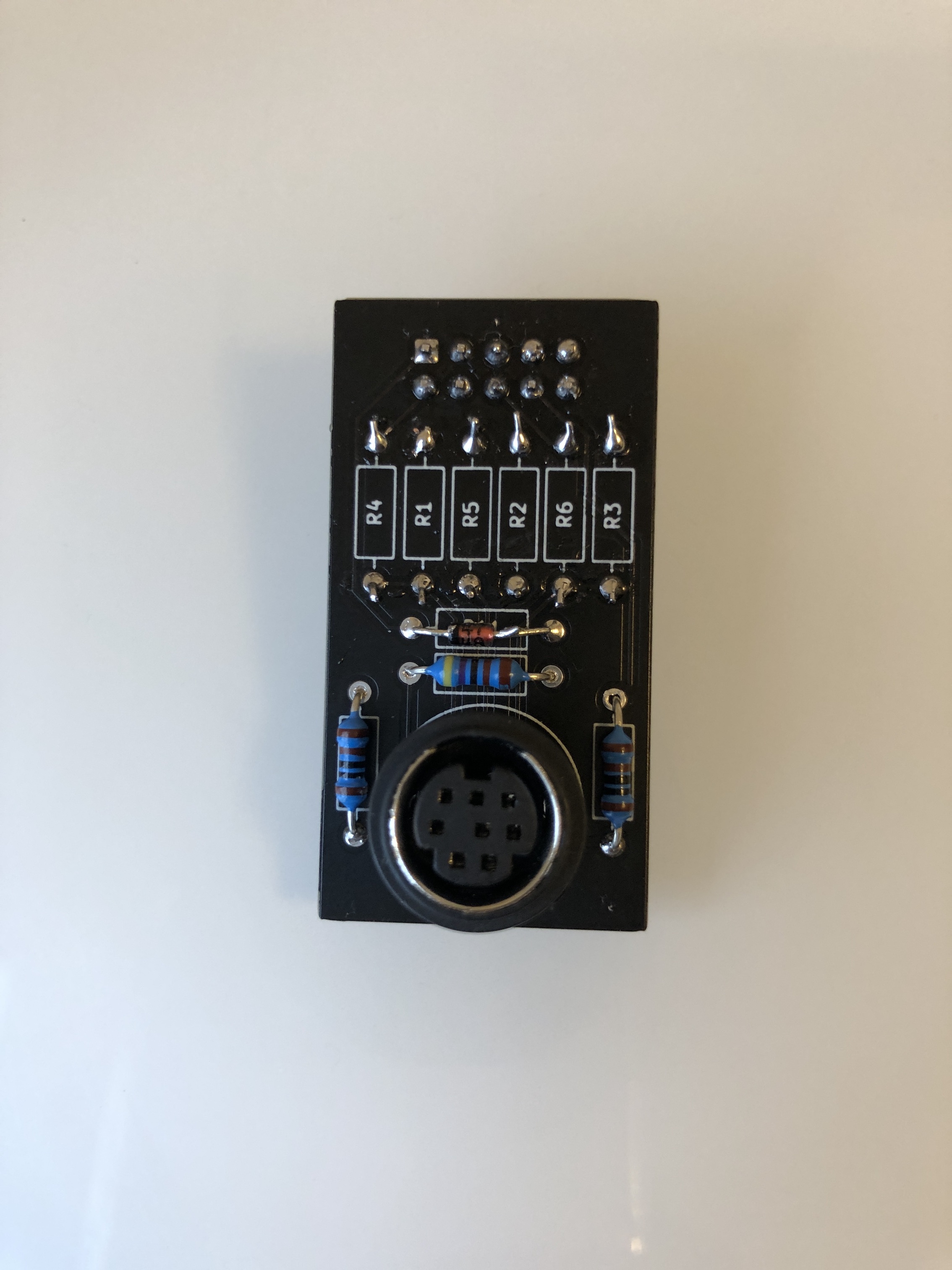
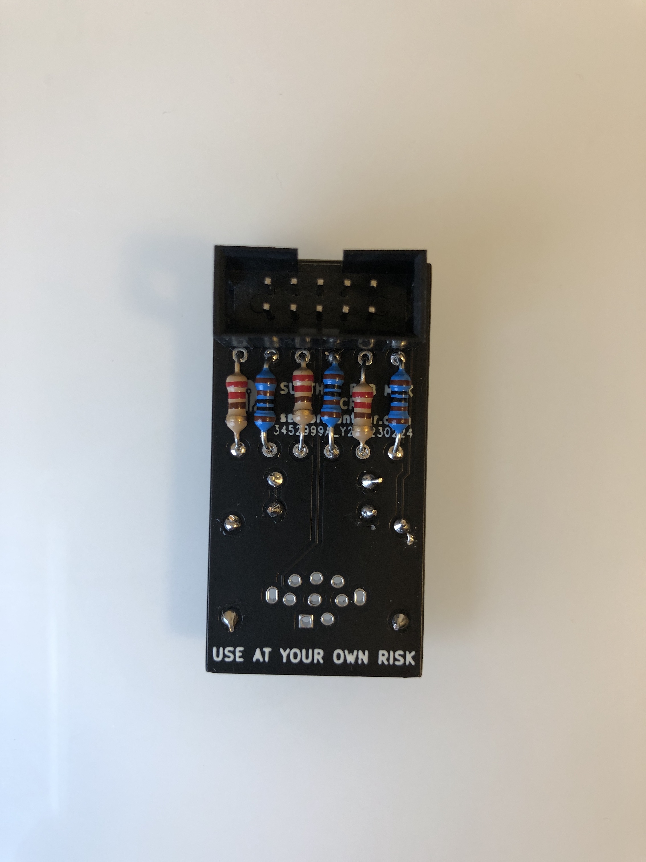
STEP 5: Build your mux board
This mod uses the RGB mux board. This is optional, but will make your mod easier and stable. You can also create the circuit presented in the schematics above without the board. Please also checkout the mux calculator to play with your own values.
| Component | Value |
|---|---|
| RGB/OSD inline resistor (chassis) | 4.3kΩ |
| Removed RGB/OSD resistor (chassis) | 820Ω |
| RGB inline diode method (chassis) | Yes |
| 0.1μF caps replaced (chassis) | No |
| RGB termination (R1, R2, R3) | 220Ω |
| RGB inline (R4, R5, R6) | 1kΩ |
| Audio LR (R7, R8) | 1kΩ |
| Diode (R9) | 1N4148 |
| Blanking Ground Resistor (R10) | open |
| Blanking Resistor (R11) | 1kΩ |
| Changes on CRT chassis | CXF0933 |
|---|---|
| Resistors removed - R204, R205 and R206 | 820Ω |
| Replace 56Ω with 1N4148 diode | 1N4148 |
| Add 3x didoes to 4.3kΩ R916, R917 and R918 resistors | 3x 1N4148 |
In this setup 4.7kΩ should produce the necessary voltage for blanking.

Service Menu
While in Standby mode, using the remote MUTE > 1 > 8 > 2 > POWER should bring you to the service menu.
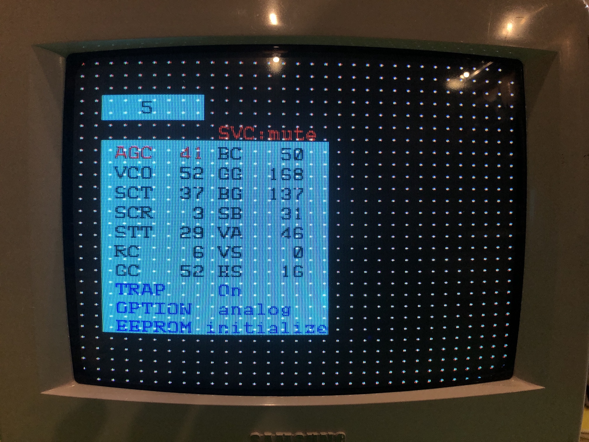
HS - Horizontal Shift was adjusted to center the RGB image
Pictures
Reference Photos

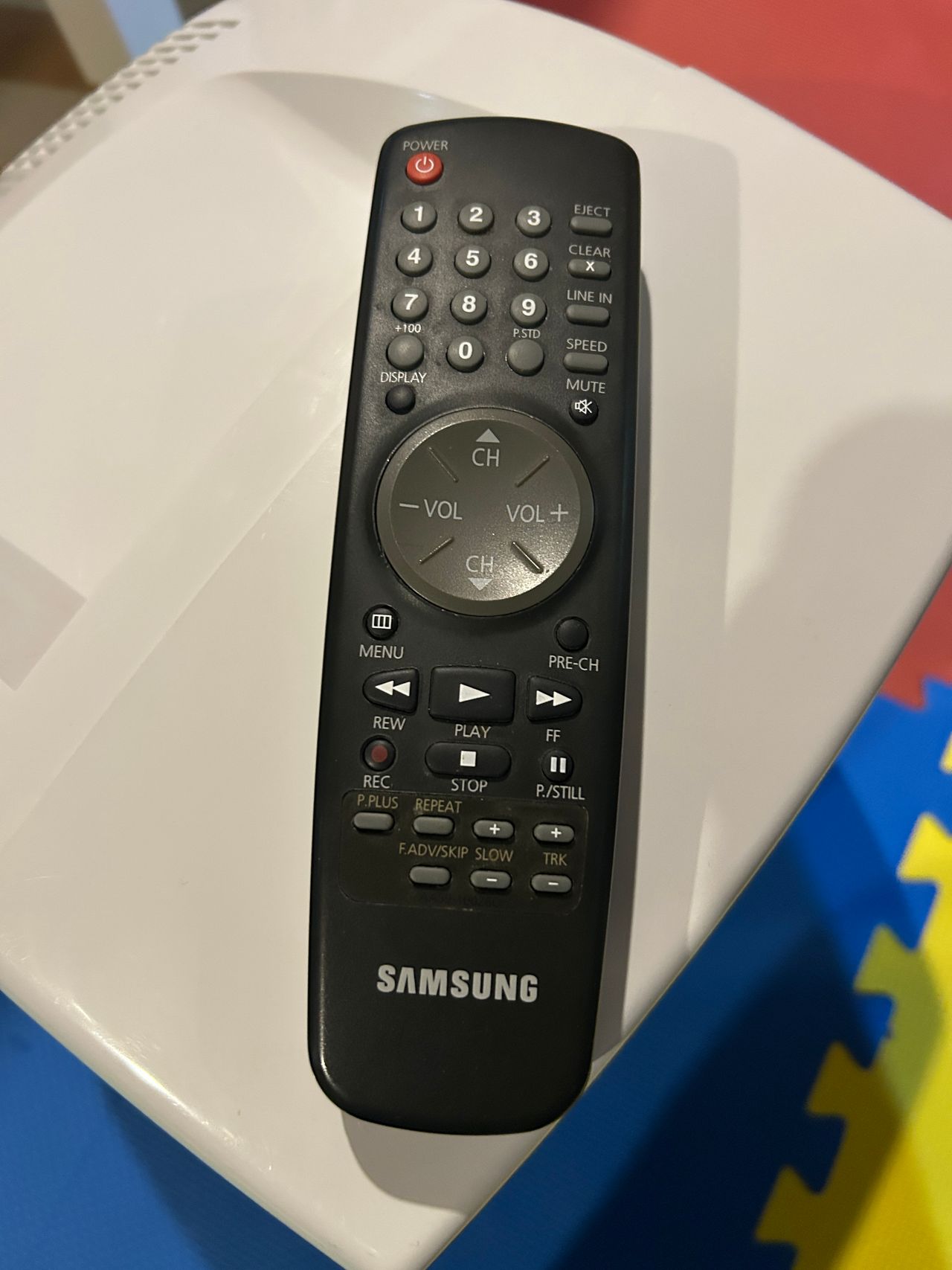
You'll need this remote to switch inputs. Line In button here allows you to do this. Also, I found that not having this remote made it inconvenient to get into the service menu.
See more photos and contributions →
Pictures
Games
Sega Genesis - Sonic 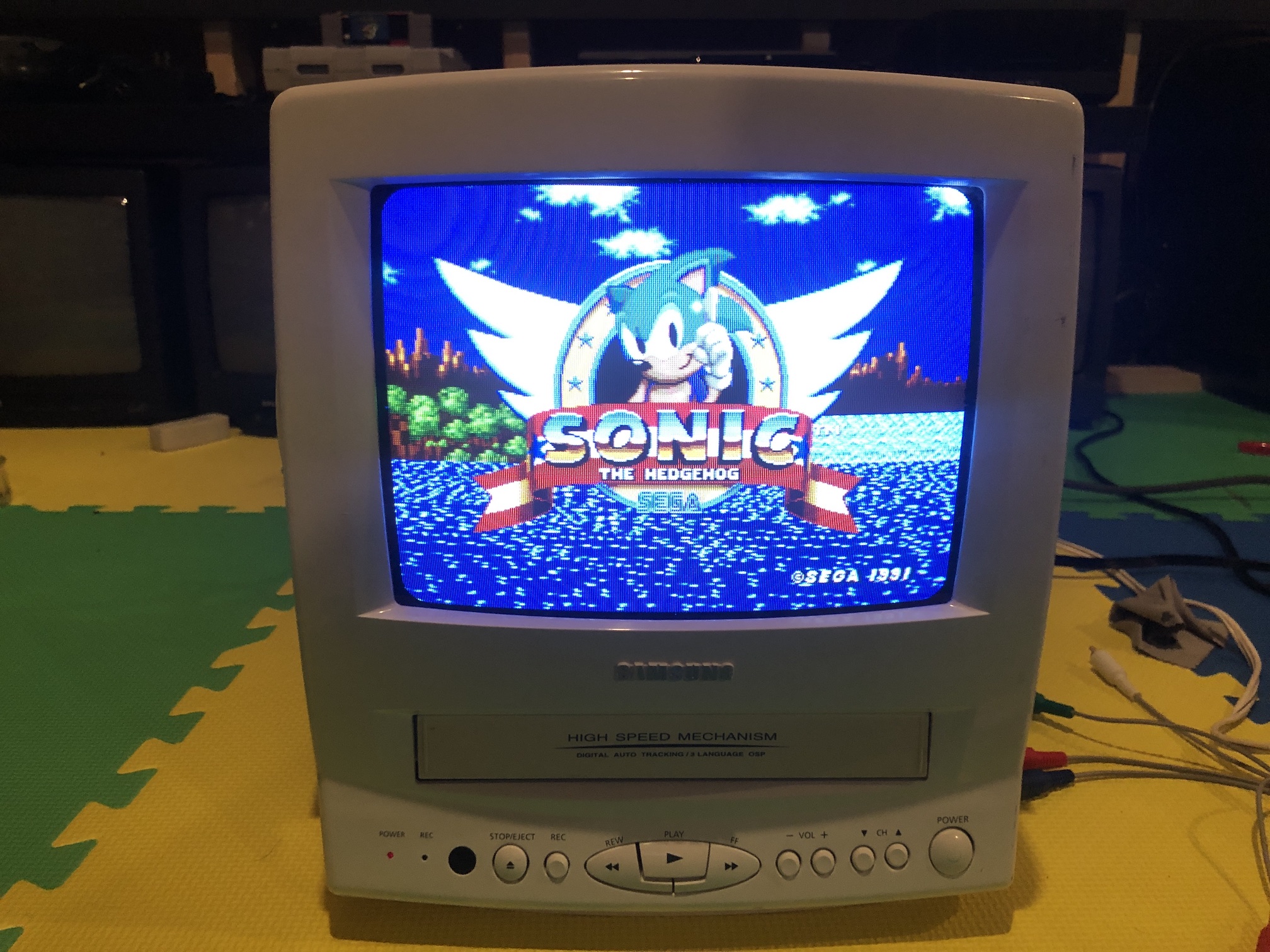
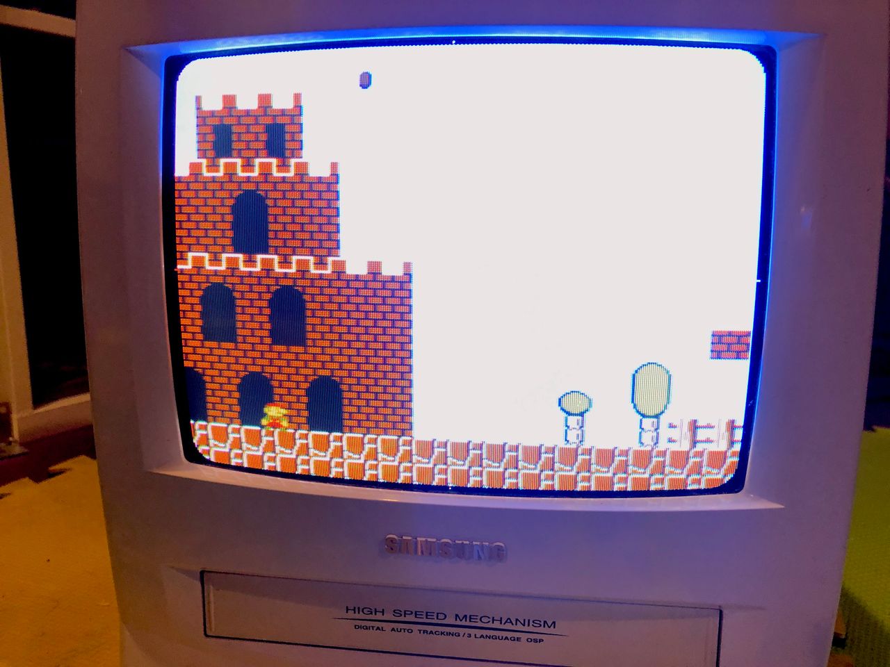
NES - Adventure Island 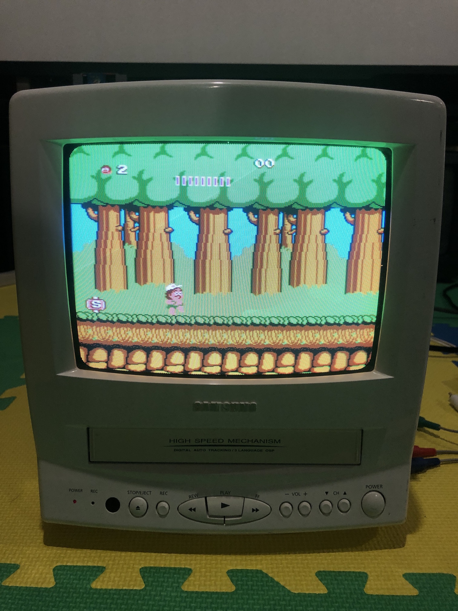
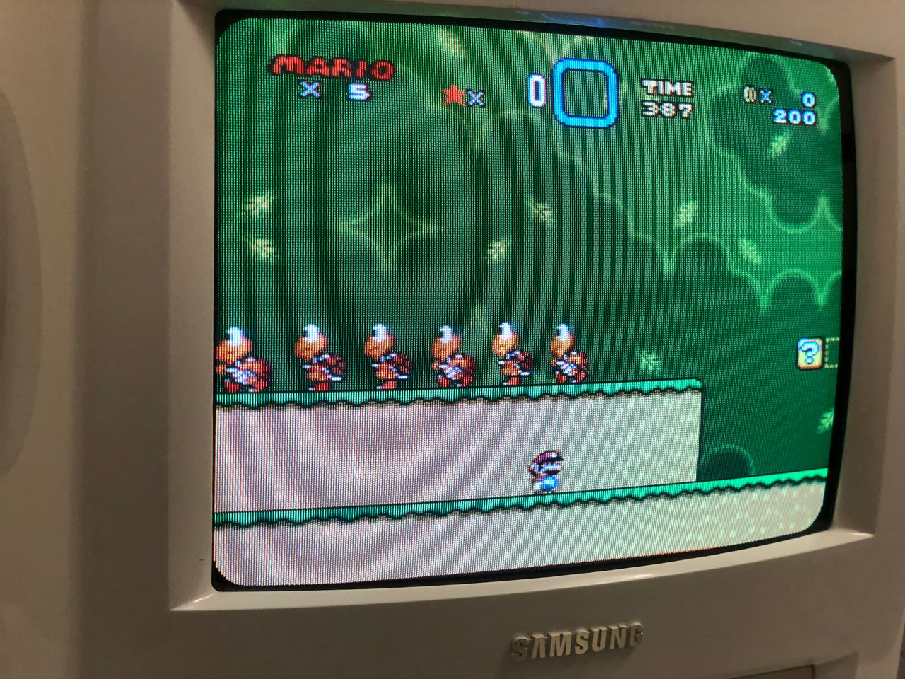
NES - Super Mario 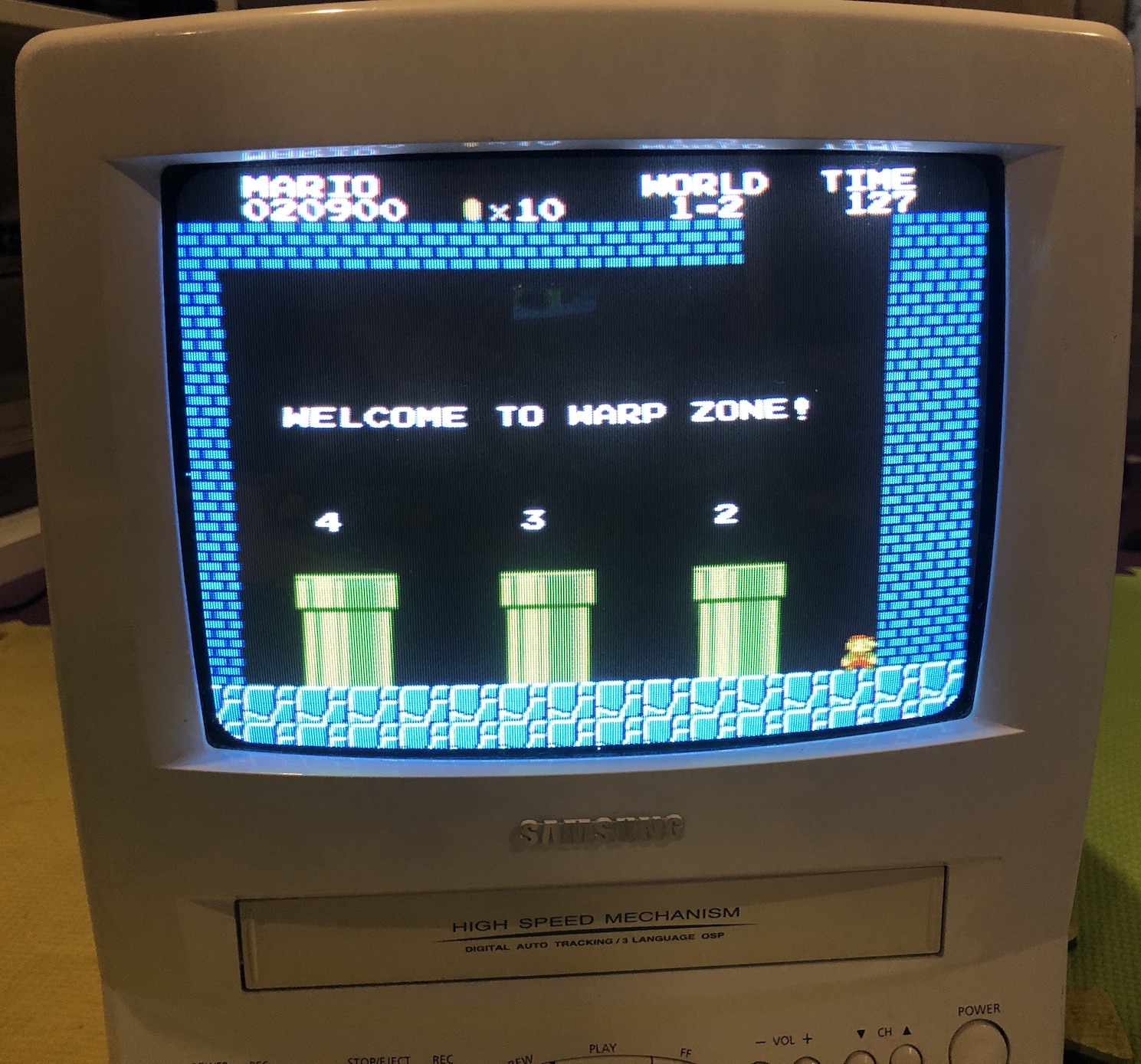
SNES - Contra III 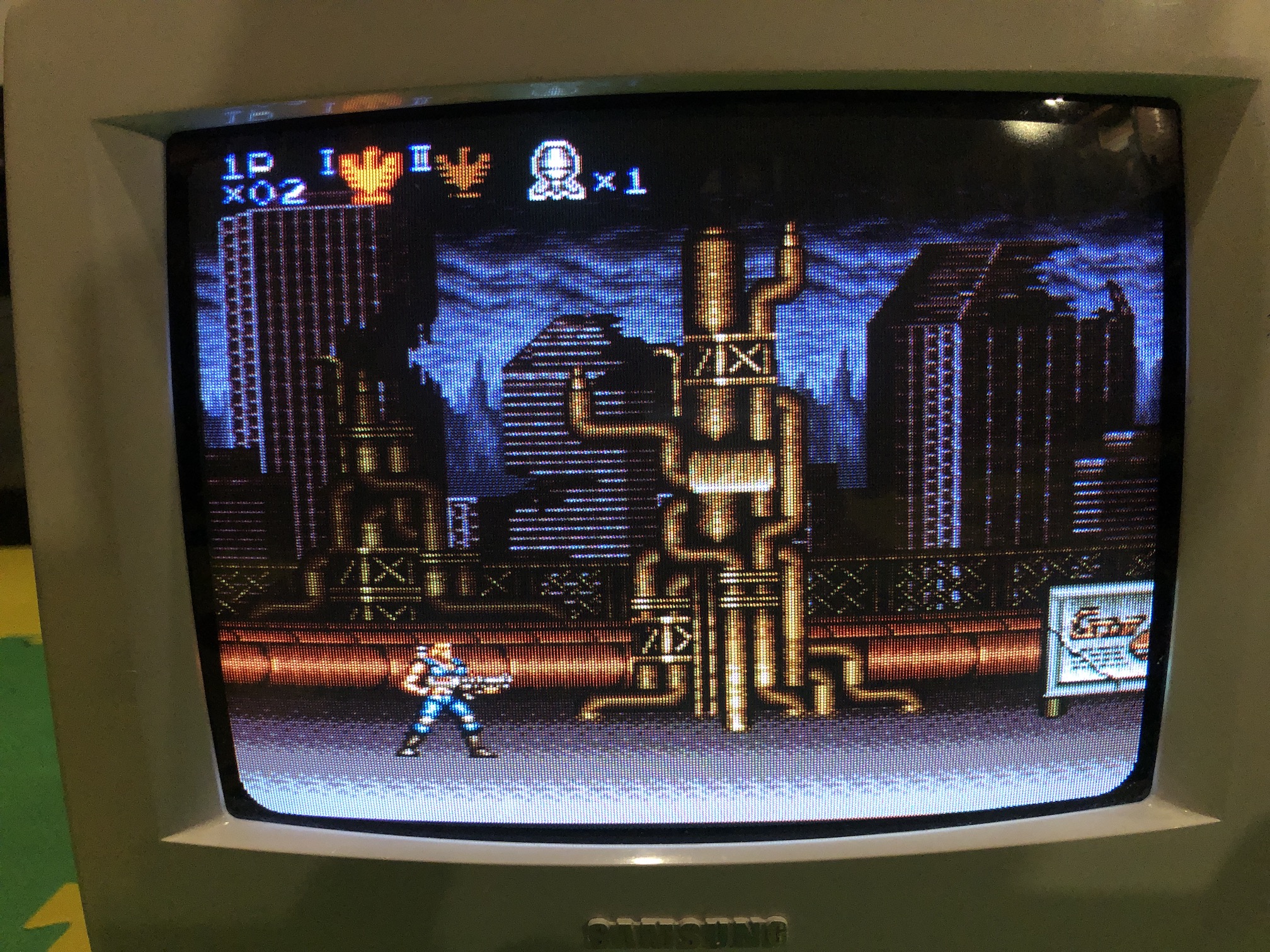
SNES - Contra III Closeup 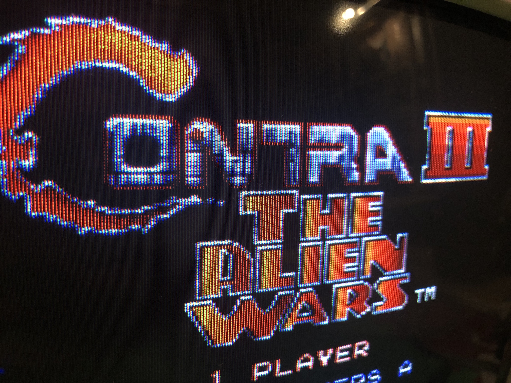
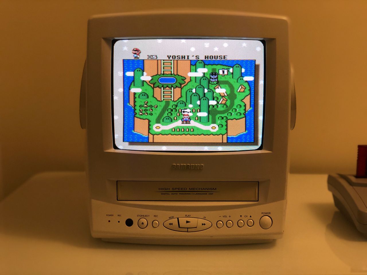
SNES - Super Mario World Closeup 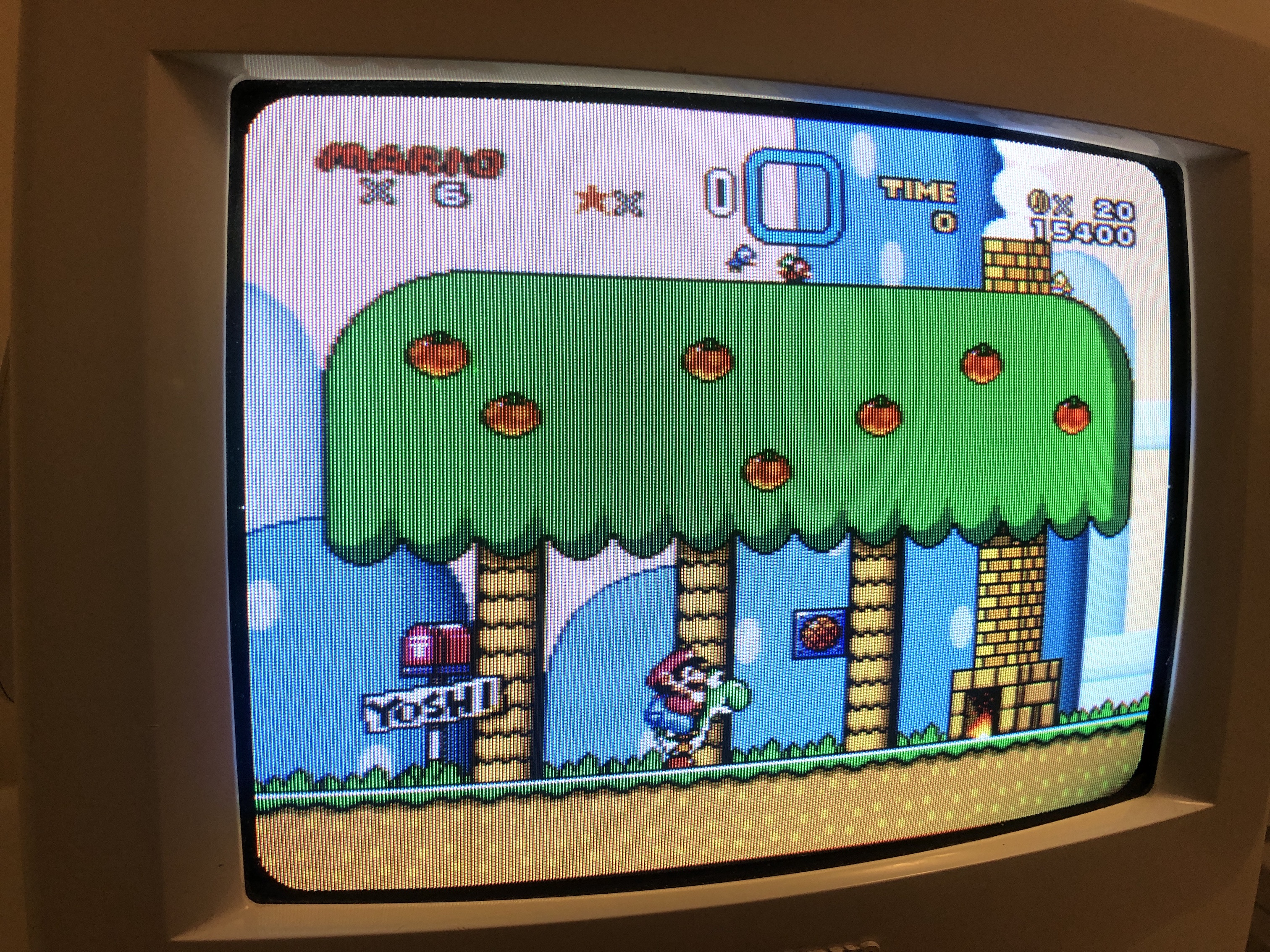
SNES - Metroid Closeup 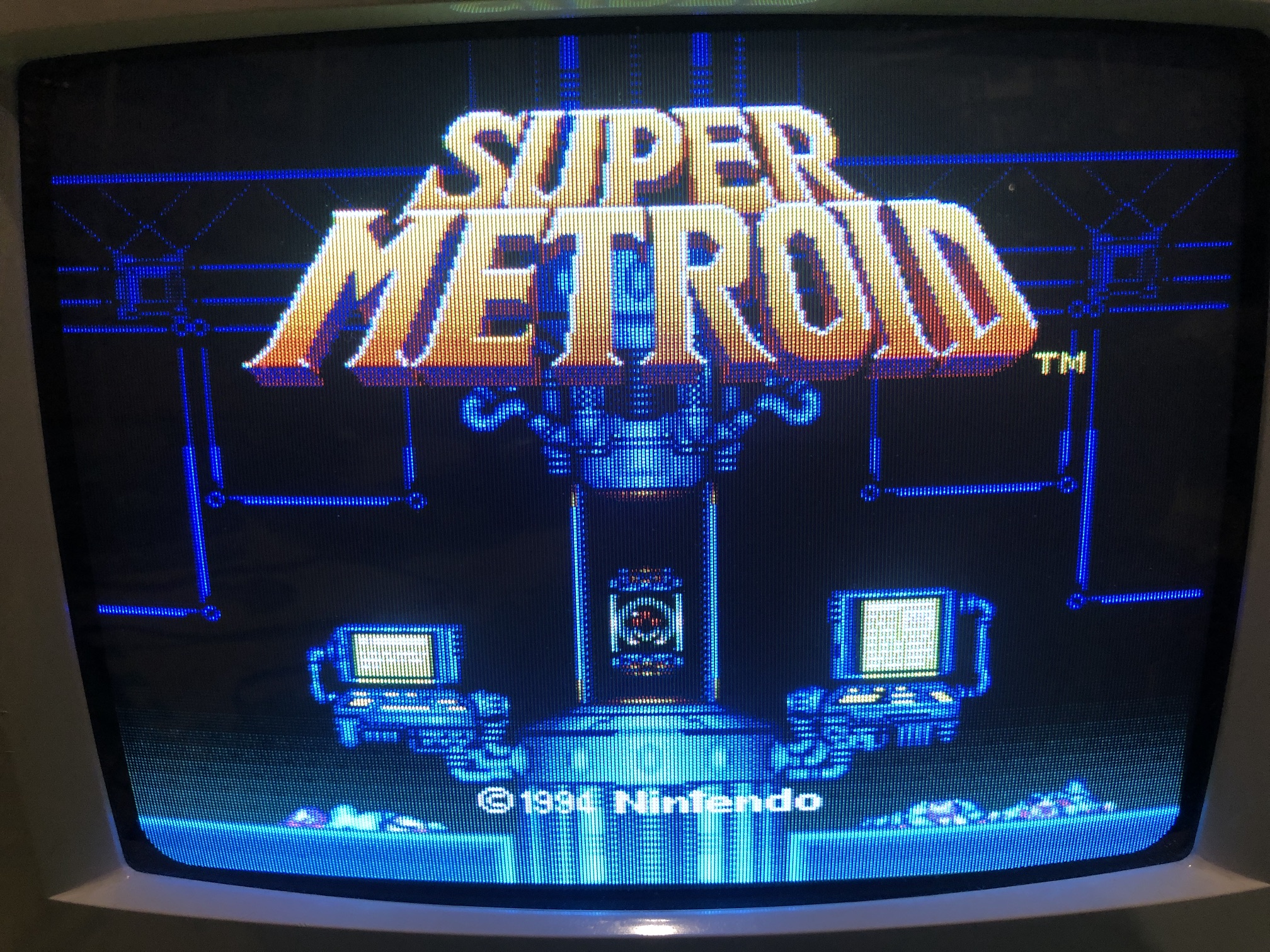
VHS
Commando - Not liking a picture taken 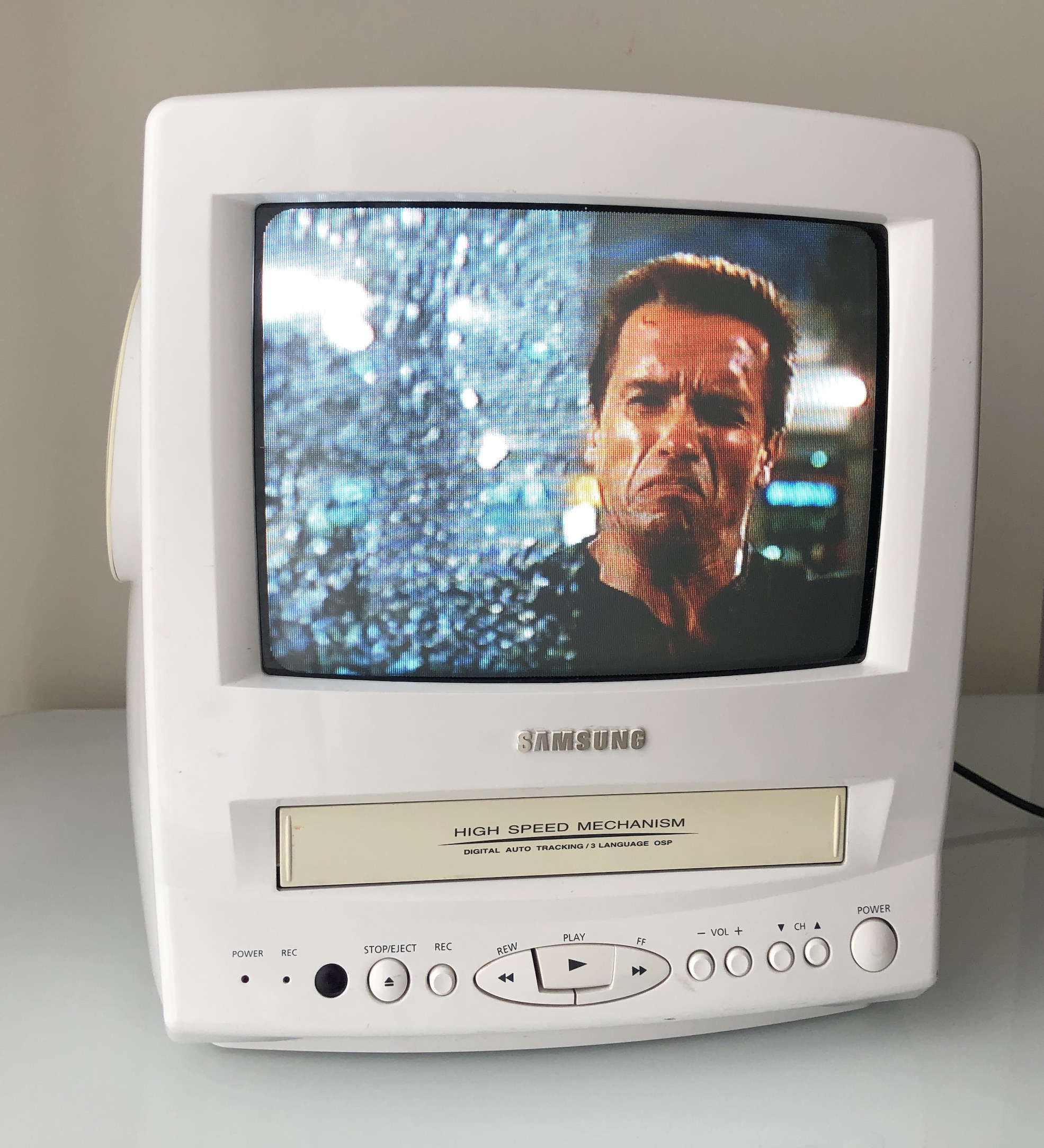
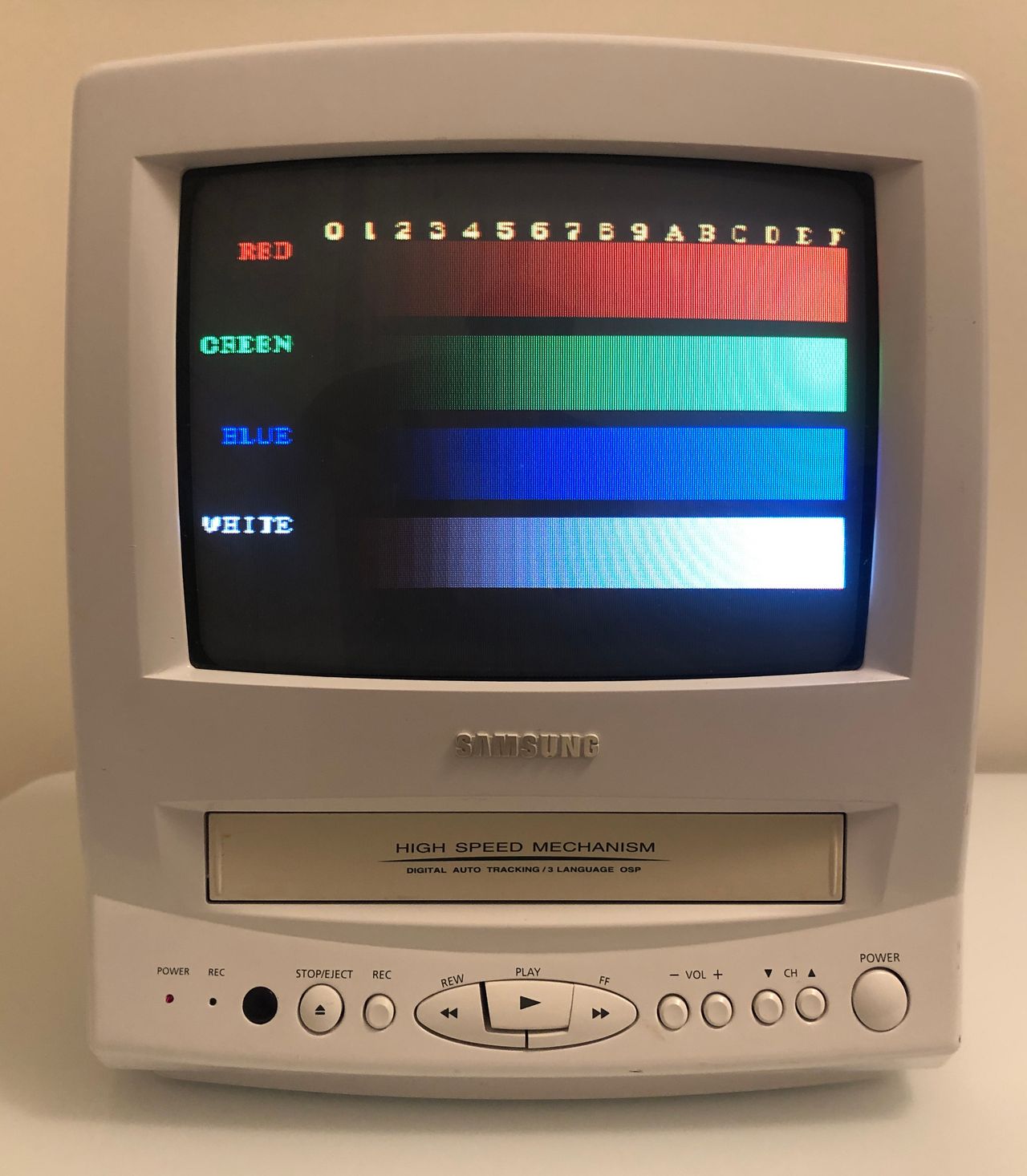
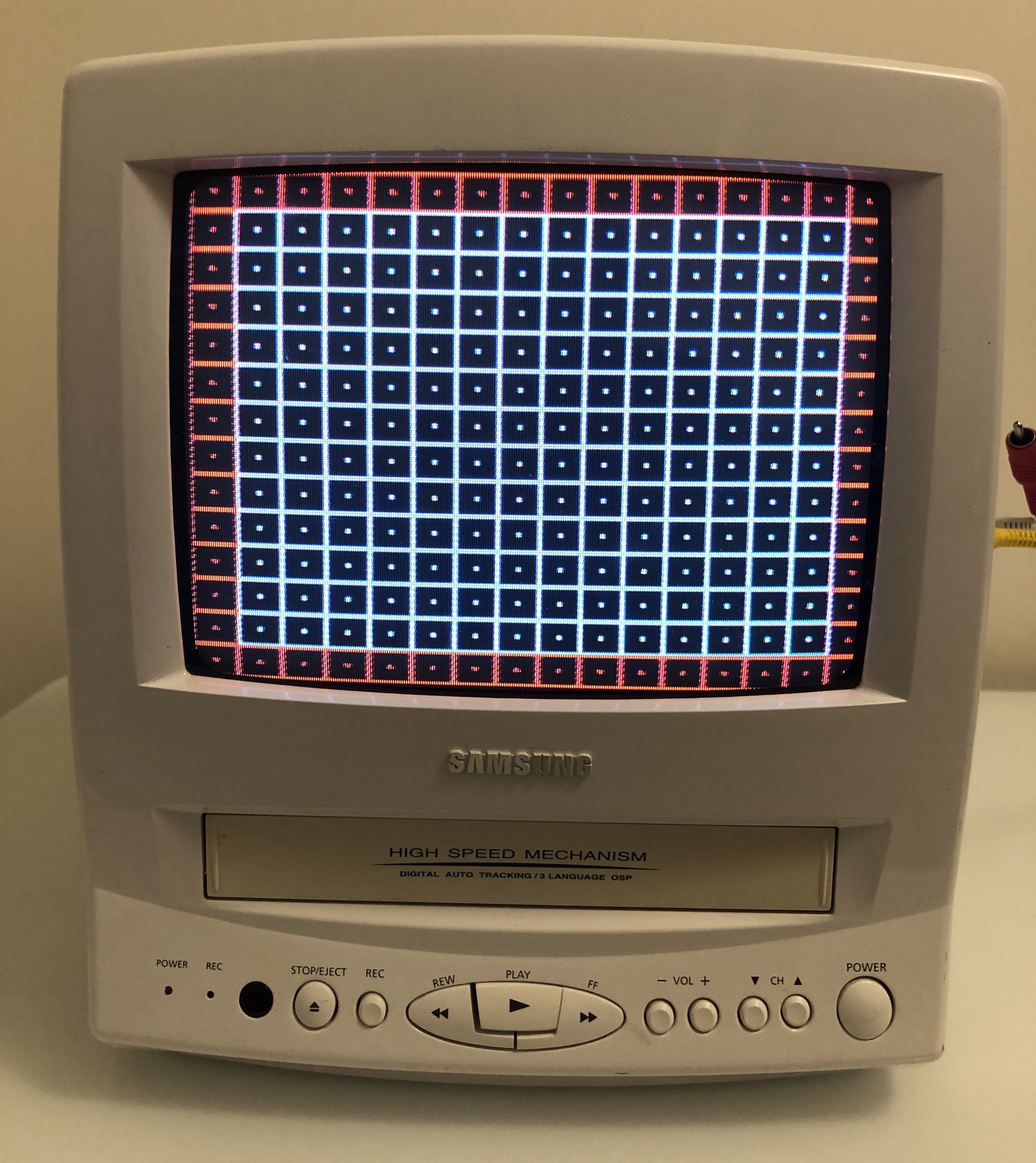
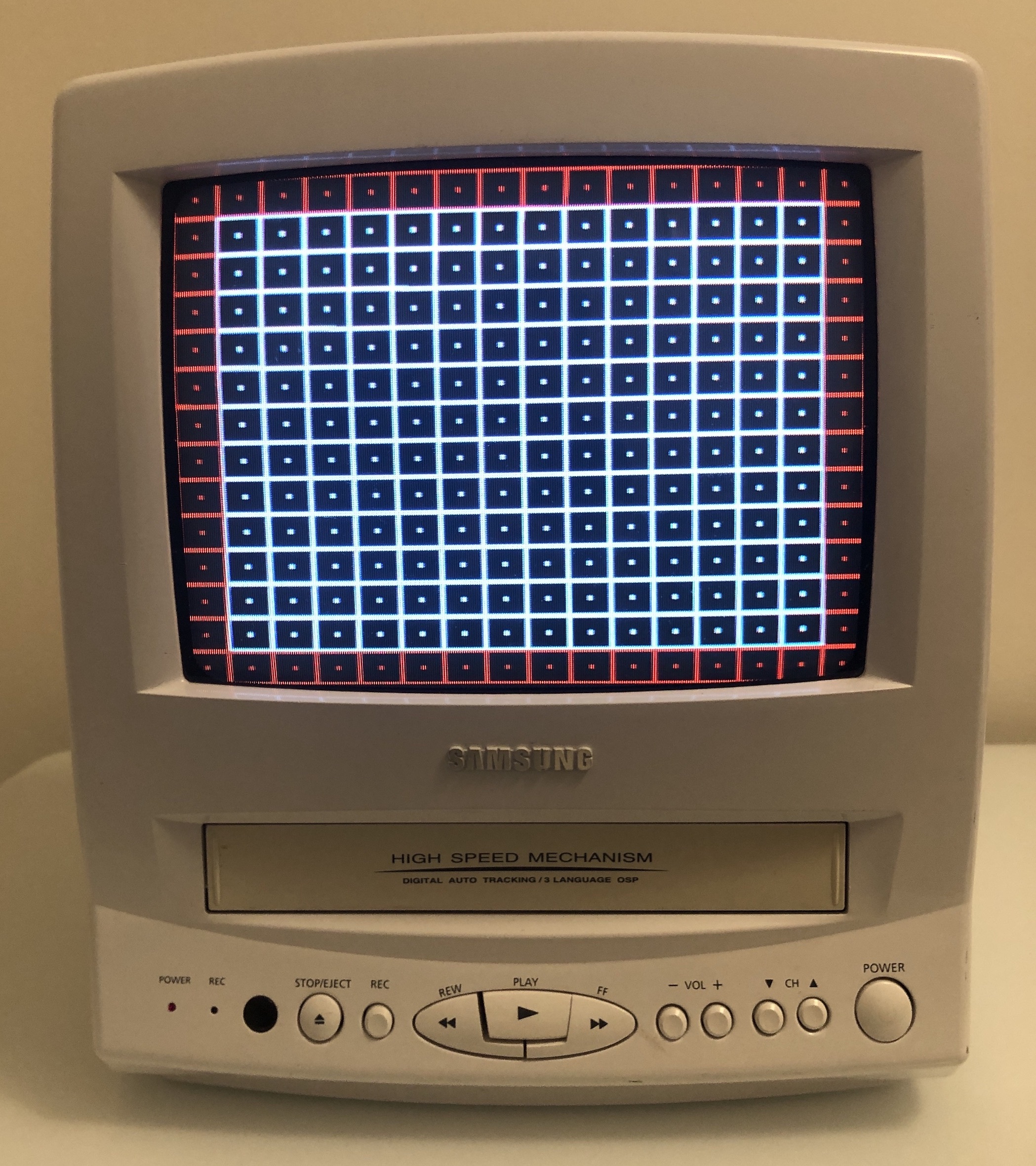
Patterns
Grid composite vs RGB
Issues noticed
CRT volume is really low
The CRT volume was super low. Volume buttons worked, but increasing and descreasing the volume only resulted in low volume. After going through several steps found out it was actually the speaker that was defective. This CRT uses a 2.5W, 8Ω. Luckily I had a spare speaker with the same specs I salvaged from an old Toshiba AF series CRT. While the shape was different, it just worked fine and also sounded much better.
Noisy RGB video
I saw couple of video interference issues when I modded this CRT for the first time. Ringing noise, grainy noise and a jailbar. Originally I used an unshielded ribbon cable and no diodes on the RGB lines coming in from the OSD. Using the shielded cables (for RGB, Audio and Sync) + using diodes inline so that the external RGB signal only went to the chroma chip and not the OSD chip, cleared up some of the noise issues. I believe the grainy noise went away with shielded cables, jailbar issue went away with the diodes used on the RGB lines. However, the ringing noise was still there. This is hard to show on pictures, but basically looks like few ripple bands that keeps scrolling up/down slowly. This video artifact was cleaned up by adjusting the blanking voltage and adding an inline diode to prevent current from going back to the OSD chip's blanking pin. Having the RGB tuner board that I built came in very handy here. 4.7kΩ worked well as the inline resistor for blanking.
Read more about how to fix the noise issues here.