Sony (BA-4) KV-27S45
Sony (BA-4) KV-27S45 CRT RGB mod
The Sony KV-27S45 is a 27" curved screen CRT television. Sold in the late 1990s as part of Sony’s highly regarded Trinitron line, it remains a favorite among CRT enthusiasts for its excellent geometry, reliable tubes, and vibrant color reproduction.
This CRT can be RGB and component modified. It shares the same tube as other BA-4 27" CRTs. Example: KV-27S40.
View full CRT details and more mod examples →
This largely follows the same method as the Sony BA-4D RGB mod article. Primary difference here is the use of micro mux board. Pictures were submitted by Brett Cutler.
Instructions below should also apply to these models:
- KV-27S40
- KV-27V40
- KV-27S45
- KV-27S65
Table of Contents
Contributors
Thank you to everyone who contributed to this guide:
- Brett Cutler — contributor, RGB mod and pictures
CRT safety
Caution
You can die doing this! So read carefully! CRT TV is not a toy. Do not open a CRT TV. If you don't have any prior knowledge about handling high voltage devices, this guide is not for you. CRT TV contains high enough voltage (20,000+ V) and current to be deadly, even when it is turned off.
Plan of attack
Manuals and Datasheets
- Sony KV-27S45 Service Manual
- Sony CXA2061S Datasheet (Jungle)
- Mitsubishi M37273MF-255SP Datasheet (OSD) — Available for Pro Users only. See CRT details for access.
Specs
- Manufactured: Mexico (1998, 1999)
- Chassis: BA-4
- Jungle Chip: Sony CXA2061S
- OSD Chip: Mitsubishi M37273MF-255SP
- Screen Size: 27"
- Power: 140 W
Schematics
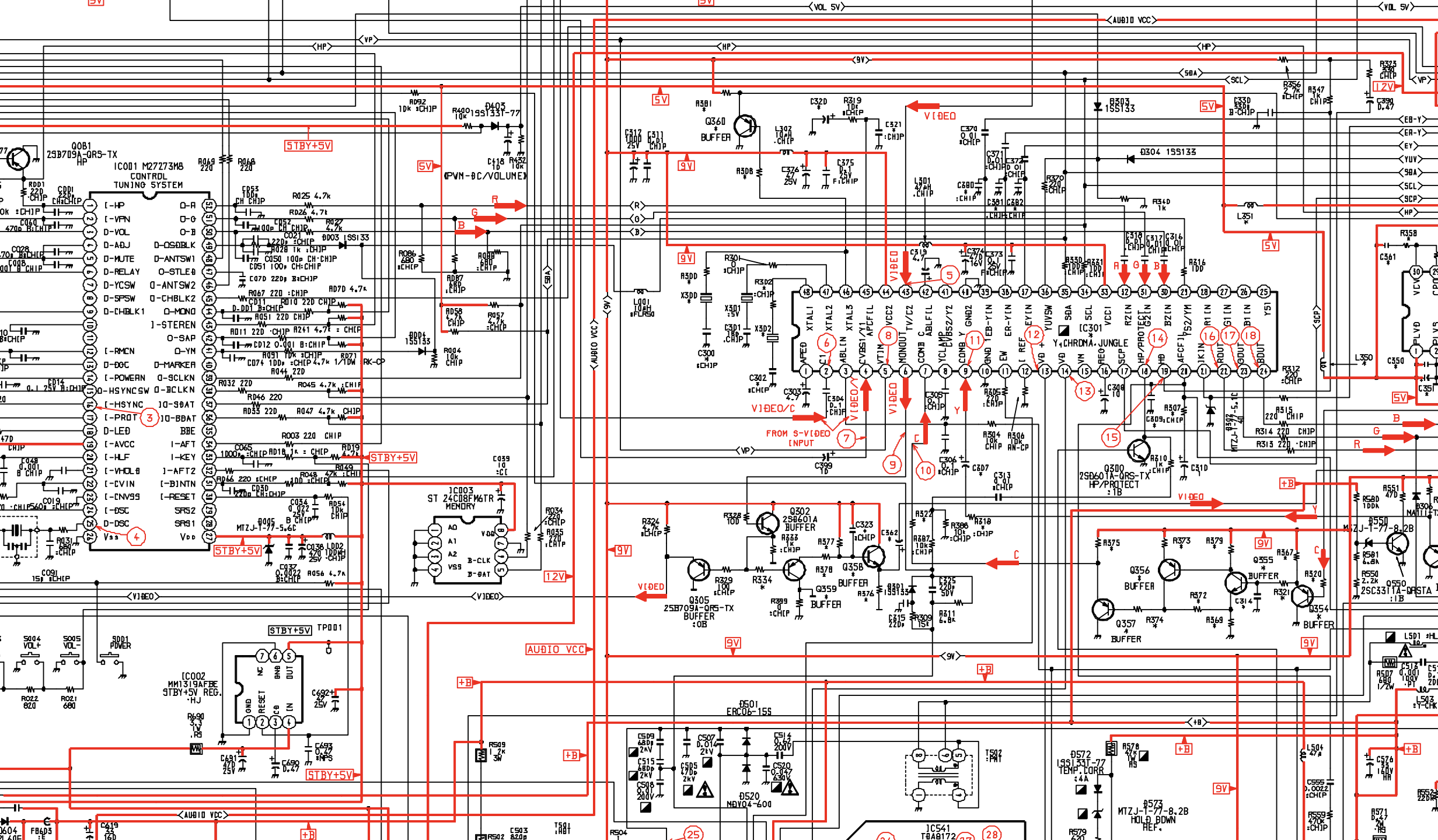
RGB mux diagram
Prepare the mux diagram. If you are building your own circuit, this diagram should help.
Performing the mod
Now that you roughly know what needs to be done, prepare for the mod. Place the board on a comfortable place. Make sure you are not putting pressure on the flyback or other components. Taking out the chassis is fairly straight forward on this CRT. There are few wires that needs to be disconnected.
- Degauss wire
- Power wire
- Ground wire attached to the neck board
- Yoke deflection coil wire
- Anode wire (this is the one with the rubber cap)
- Left and right audio wires
Please remember that wires 1-5 are critical for the CRT to function and should not be omitted. Having any of these wires disconnected while powering up can damage the board and can have adverse effects.
STEP 1: Remove the following components
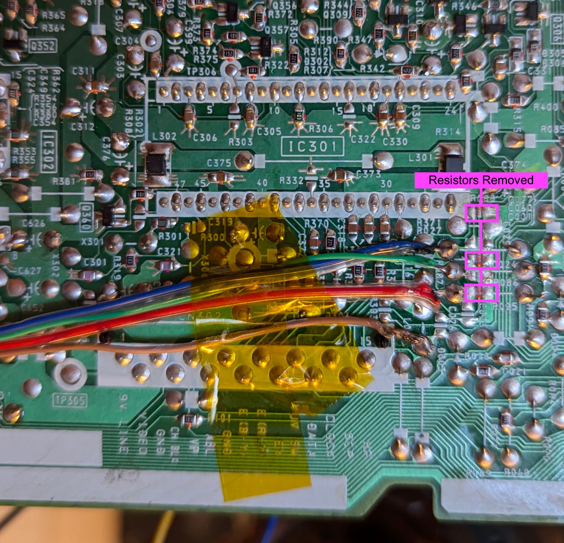
Remove the following components. RGB resistors to the ground. Please always measure and mark them, so that you know you are removing the correct partrs.
- R086 (680Ω) Red ground resistor
- R087 (680Ω) Green ground resistor
- R088 (680Ω) Blue ground resistor
STEP 2: Add RGB inline diodes (optional, but recommended)
To reduce interference, it is recommended to add these inline diodes. You will be lifting one side of the R025, R026, R027 and add diodes. Pay attention to the diode direction and how it was installed. This is extremely important. Otherwise, OSD will not work.
KV-27S45 - Heat shrink was used in the middle one to avoid shorts. 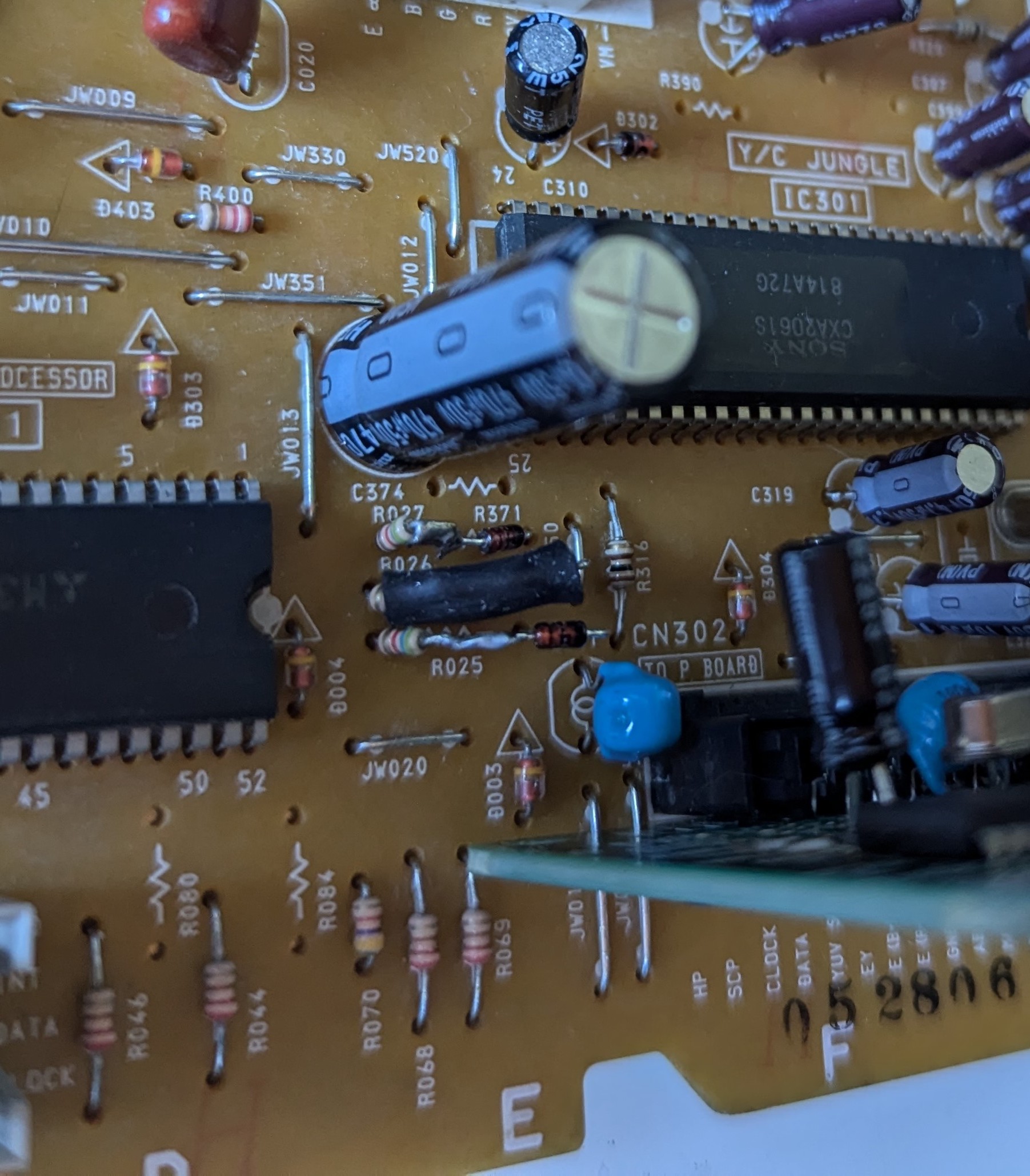
KV-27V40 - Heat shrink was used in the middle one to avoid shorts. 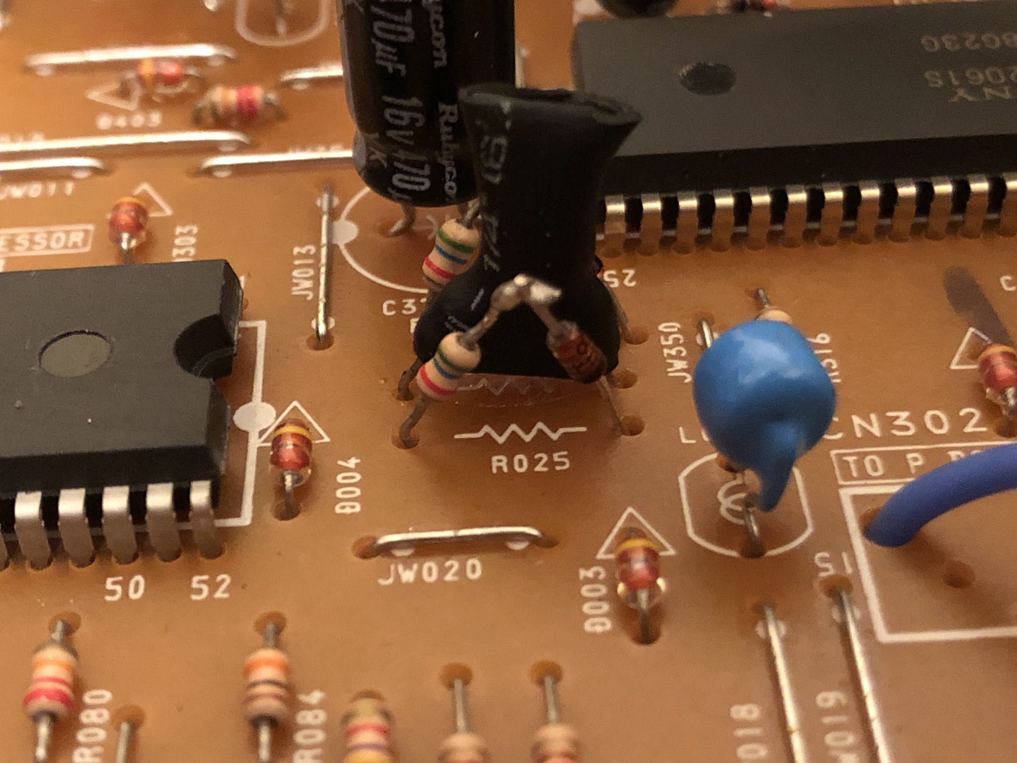
KV-27V42 - Heat shrink was used in the middle one to avoid shorts. 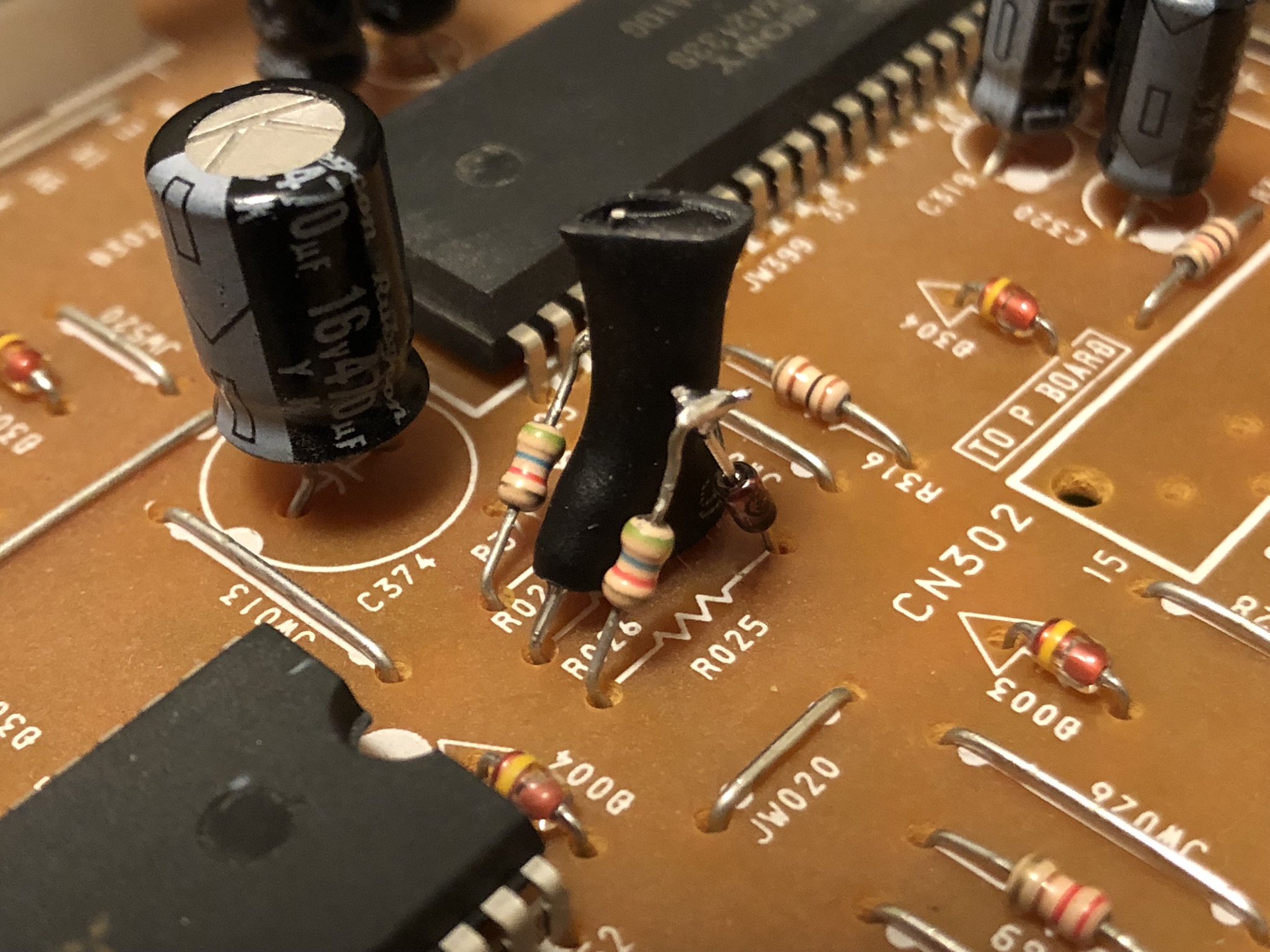
KV-27S42 - After adding diodes inline 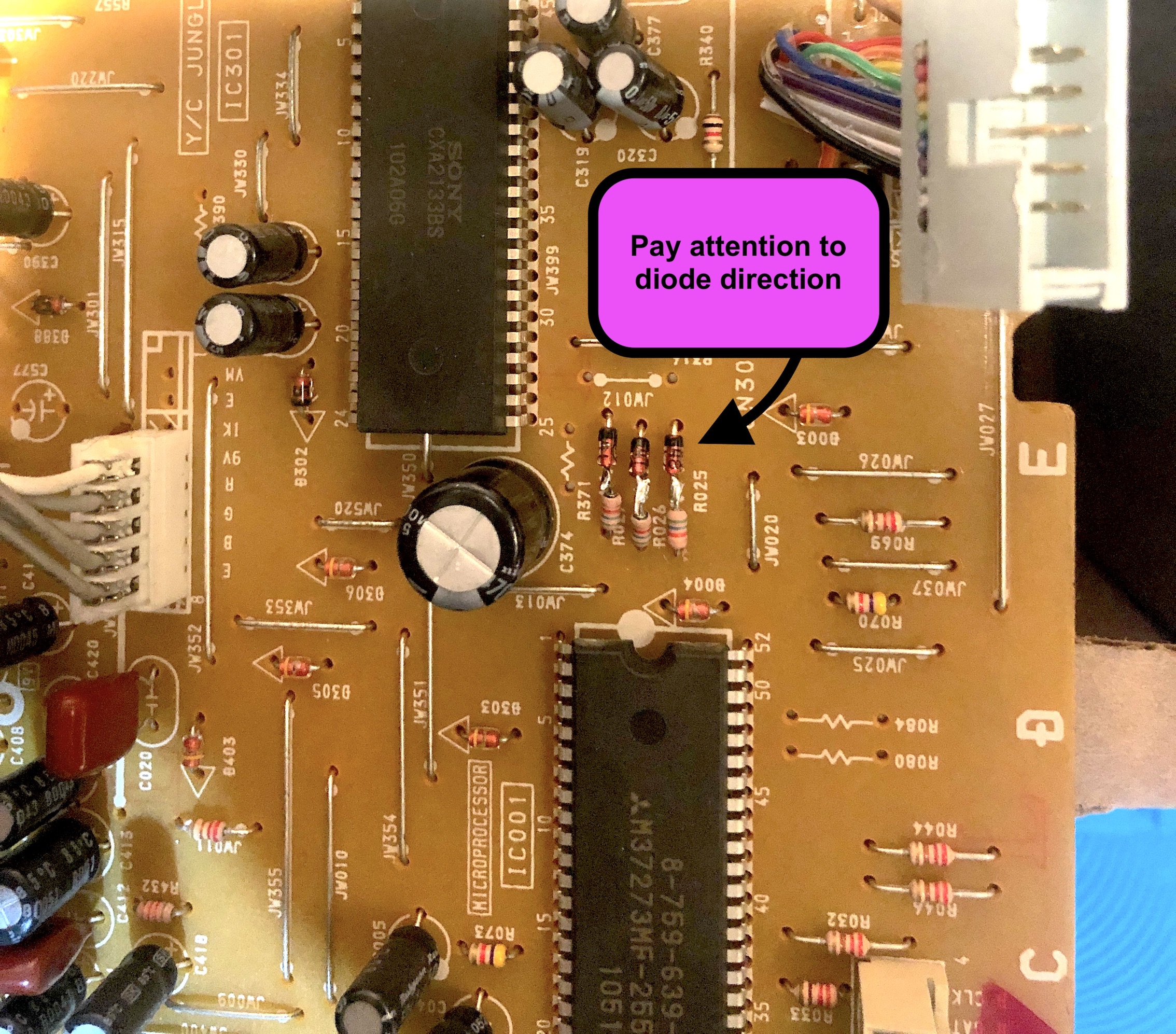
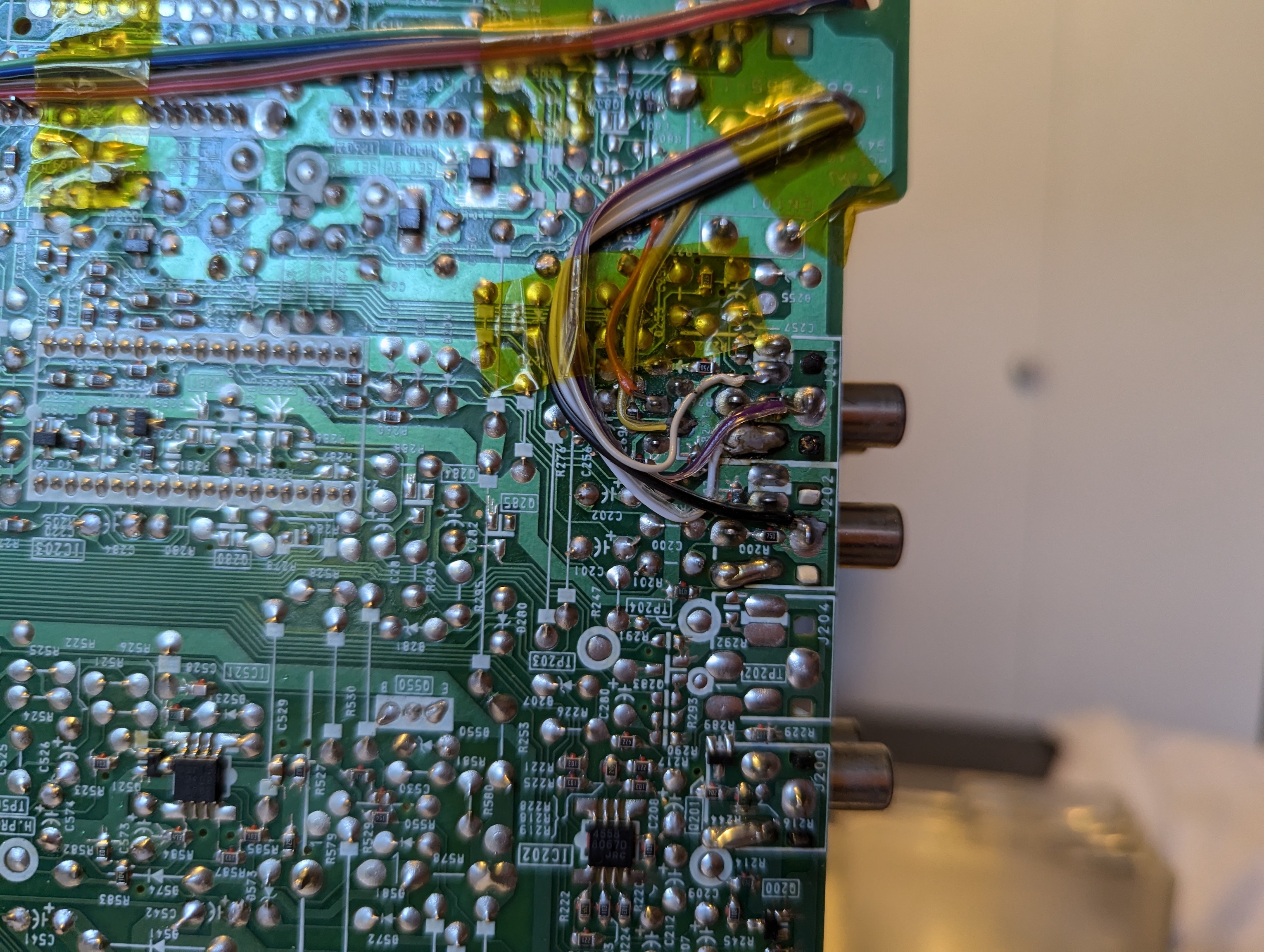
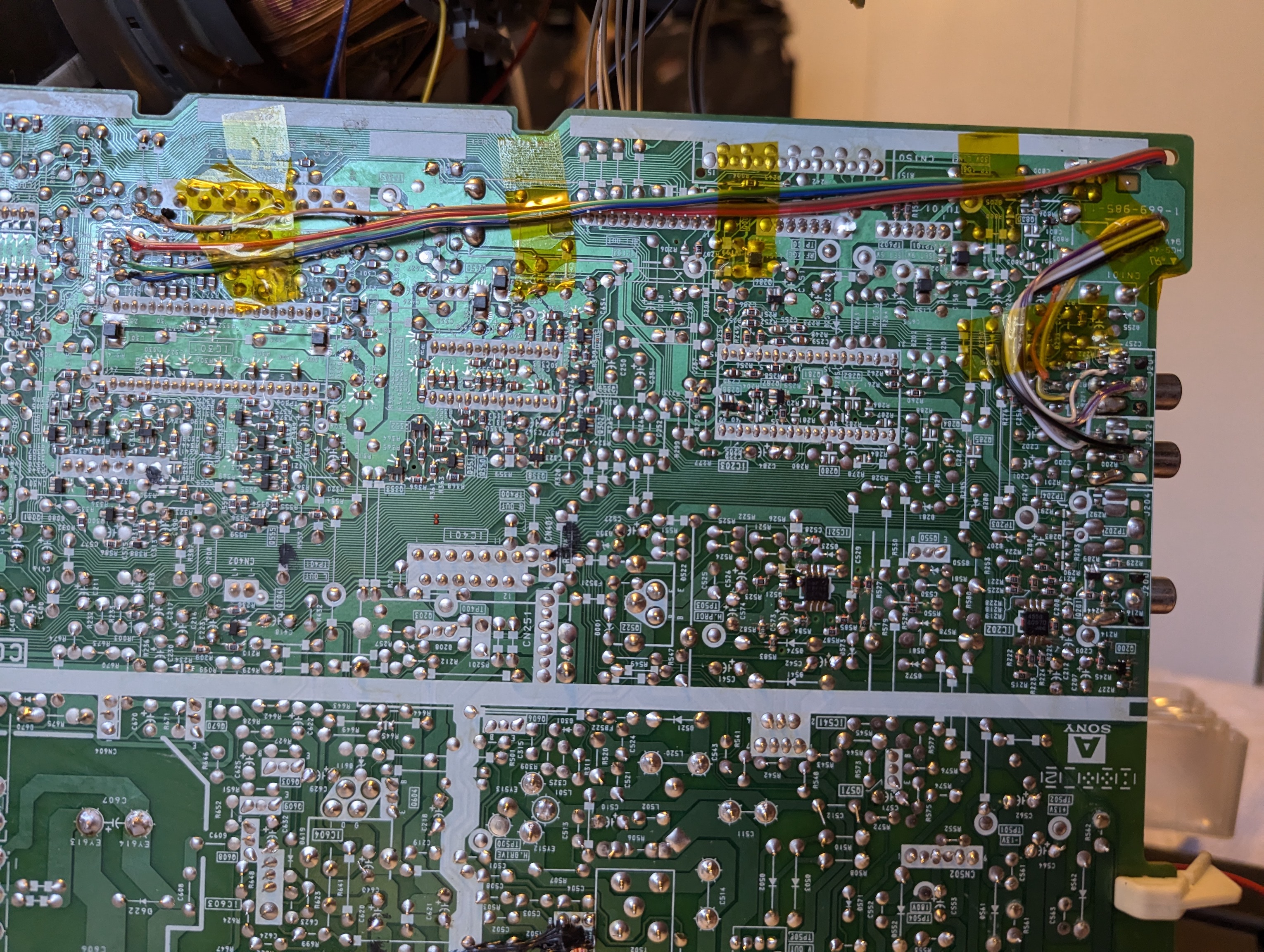
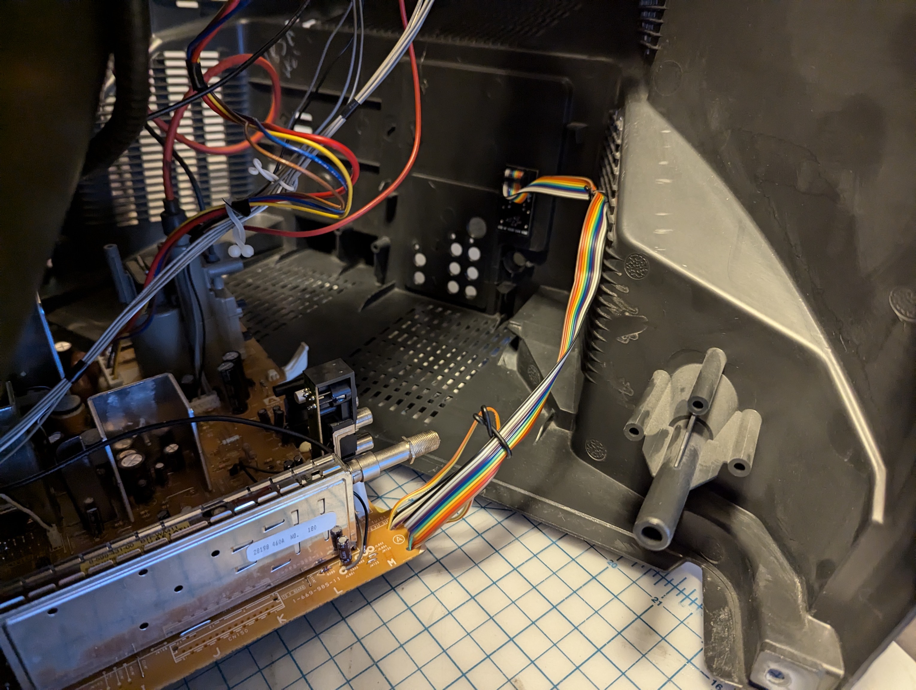
STEP 3: Solder R, G, B and blanking wires
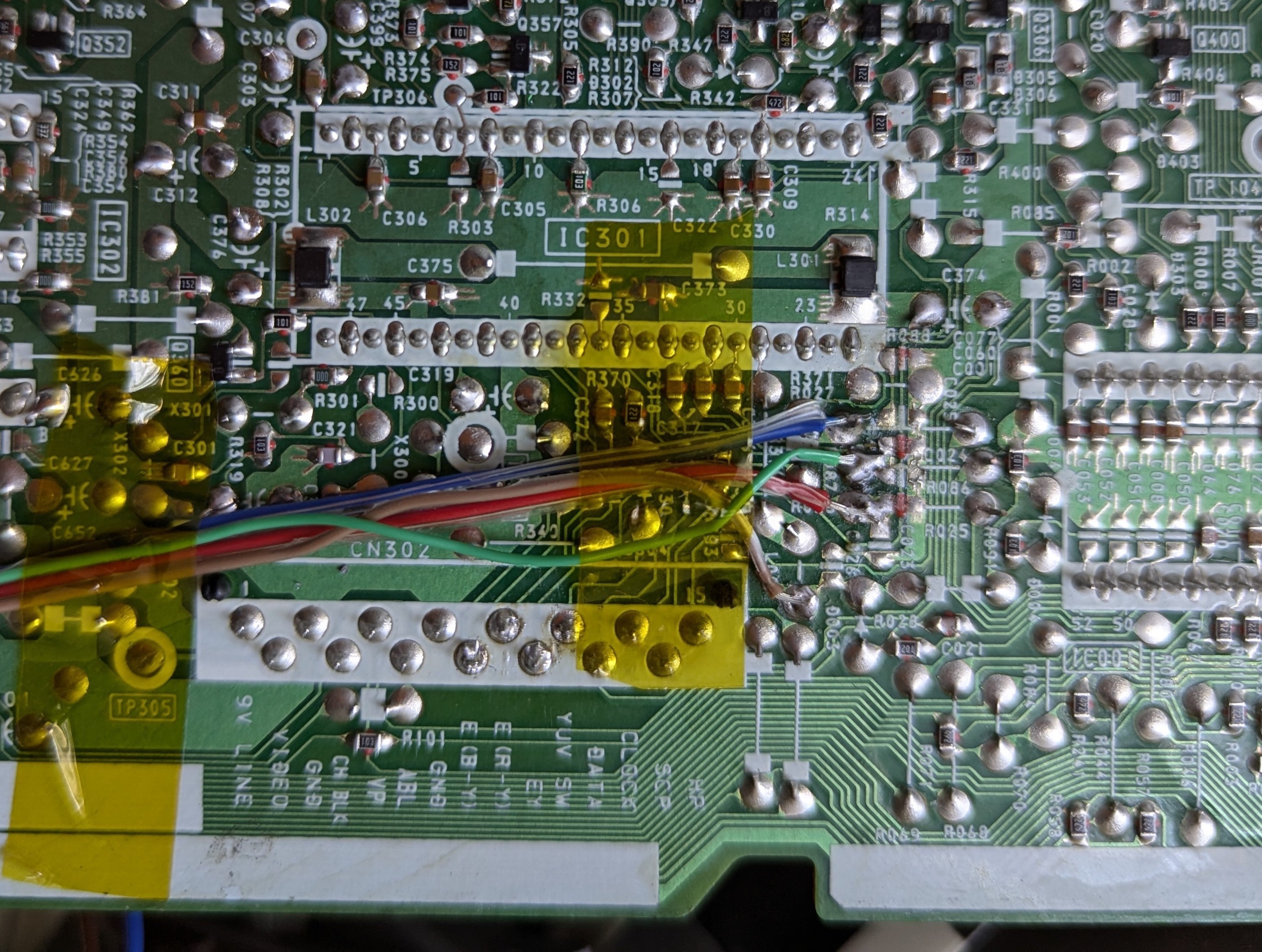
STEP 4: Solder audio, sync and ground wires
Tips
The Sony KV-27S40 model lacks an S-Video input, even though the components required for it are already populated. If you wish to use the S-Video Luma input for sync injection as seen in the photo, it is necessary to change the ID-1 setting in the service menu from "1" to "17" to enable the S-Video input. You should also wire the S-Video detection pin to ground using a SPST switch.
Where to connect Audio, Ground and Sync 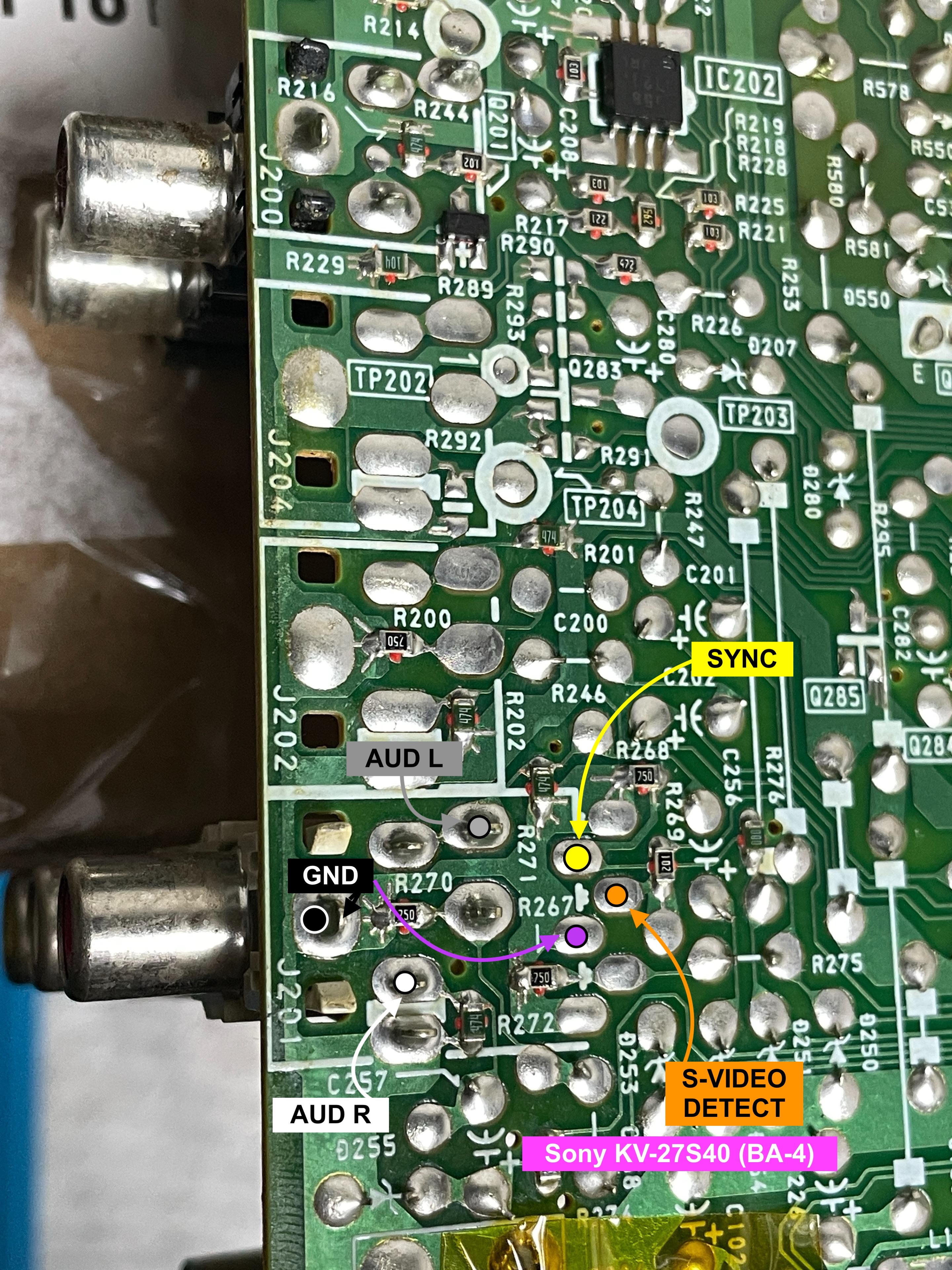
STEP 5: Build your mux board
This mod uses the RGB mux board. This is optional, but will make your mod easier and stable. You can also create the circuit presented in the schematics above without the board. Please also checkout the mux calculator to play with your own values.
| On Sony CRT Chassis | KV-27S45 |
|---|---|
| CRT RGB inline resistor | 5.6kΩ |
| CRT RGB ground resistors removed | 680Ω |
| 0.1μF caps replaced | No |
| Add diodes on chassis RGB lines? | Yes |
| Add blanking diode on chassis | No |
| RGB mux board | KV-27S45 |
|---|---|
| Mux board RGB termination (R1, R2, R3) | 75Ω |
| Mux board RGB inline resistors (R4, R5, R6) | 1kΩ |
| Mux board Audio LR (R7, R8) | 1kΩ |
| Mux board blanking diode (R9) | 1N4148 |
| Mux board blanking ground resistor (R10) | open |
| Mux board blanking resistor (R11) | 1kΩ |
| Mux board transistor base resistor (R12) | 1kΩ |
| Mux board transistor (Q1) | PN2222A |
Compatible mux boards:
!Important. There is method to installing the micro board. Please follow this tutorial for the steps you should take to install the micro board.

Pictures
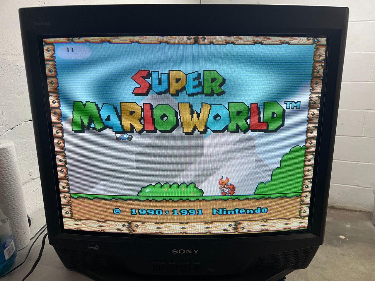
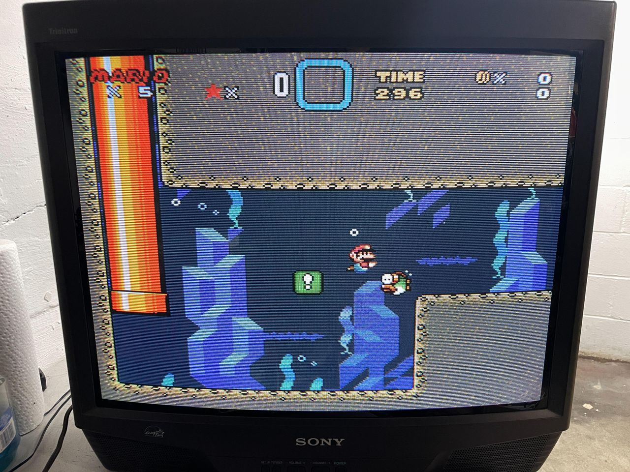
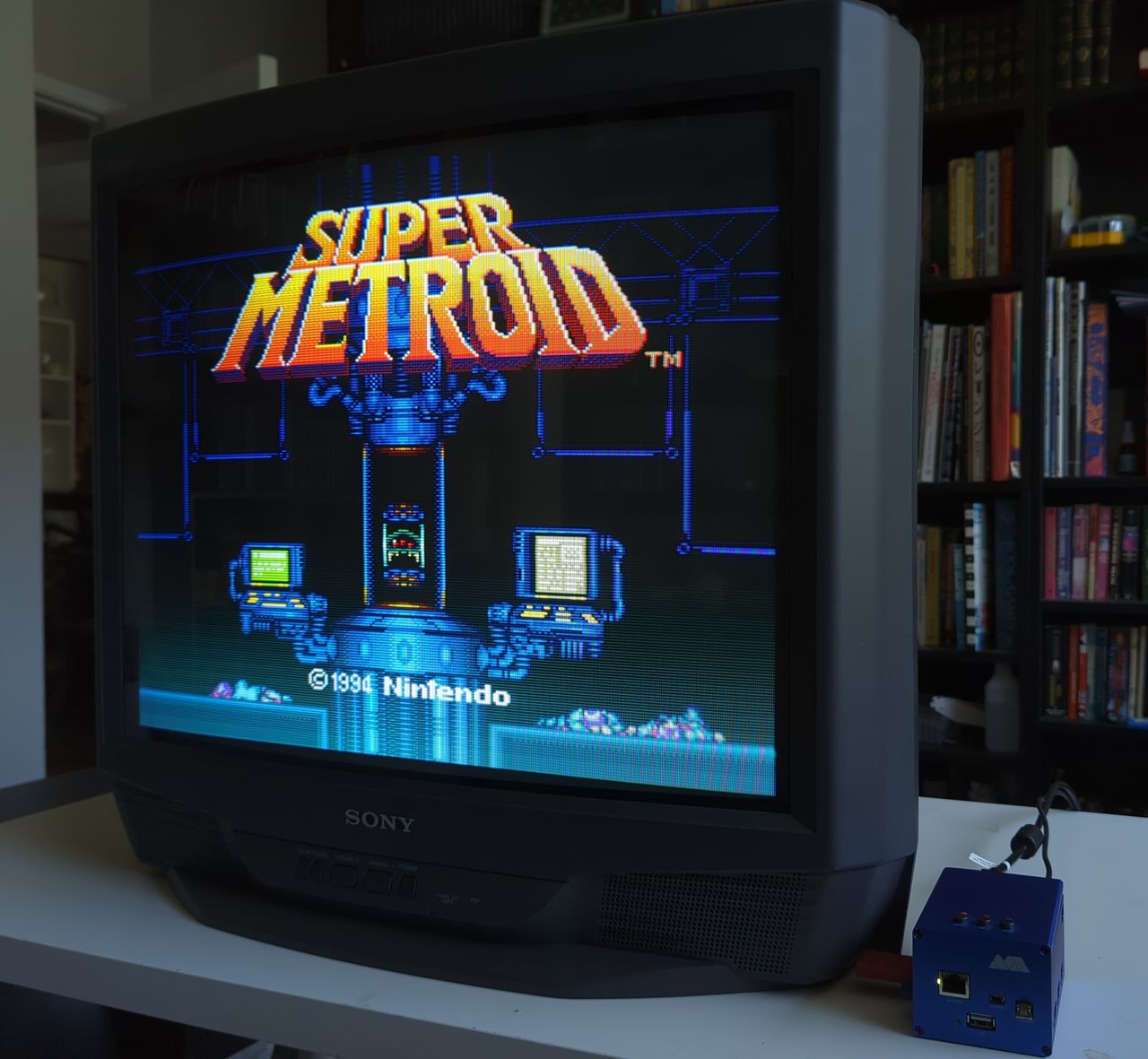
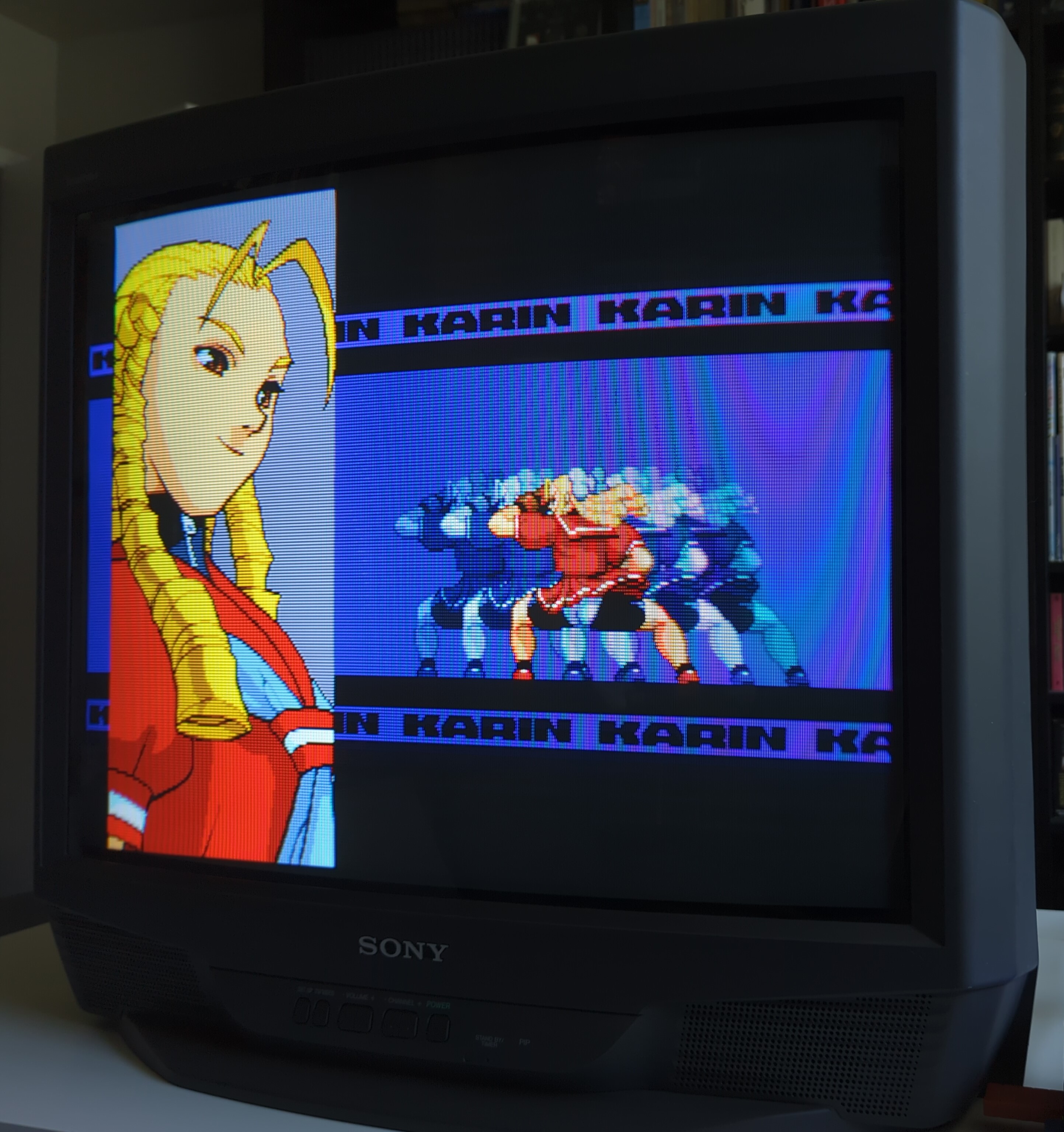
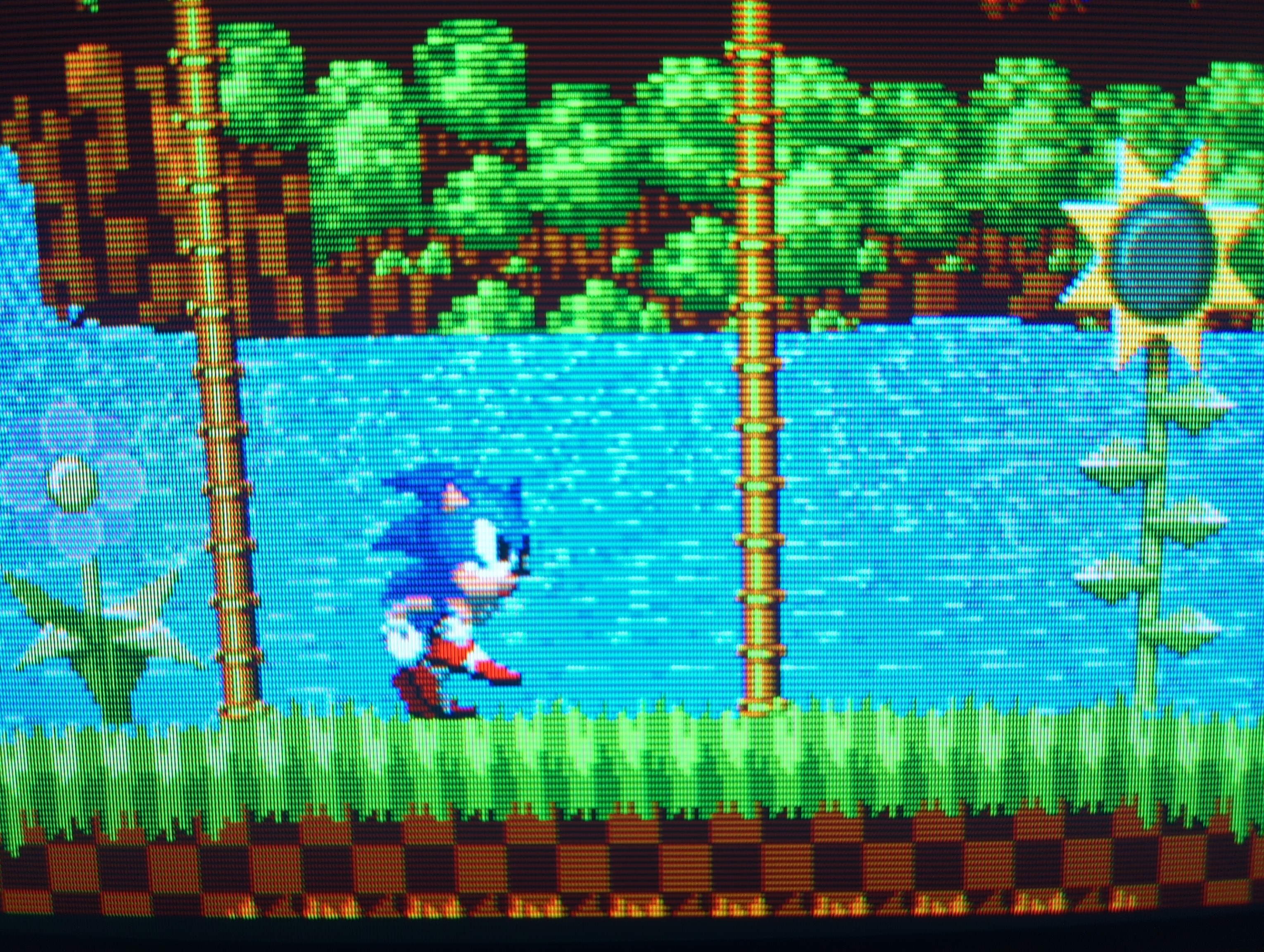
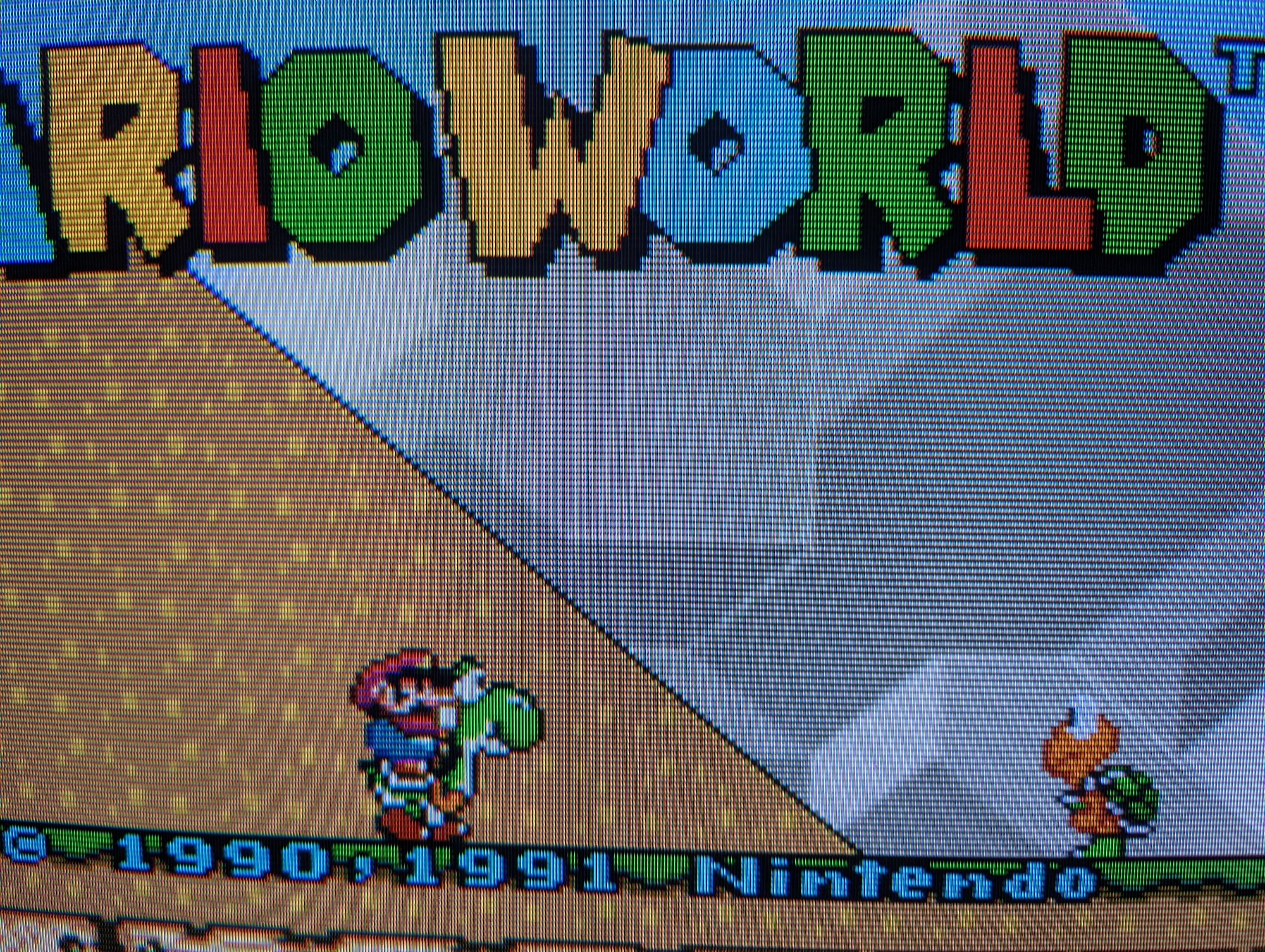
Games


Set
Chassis 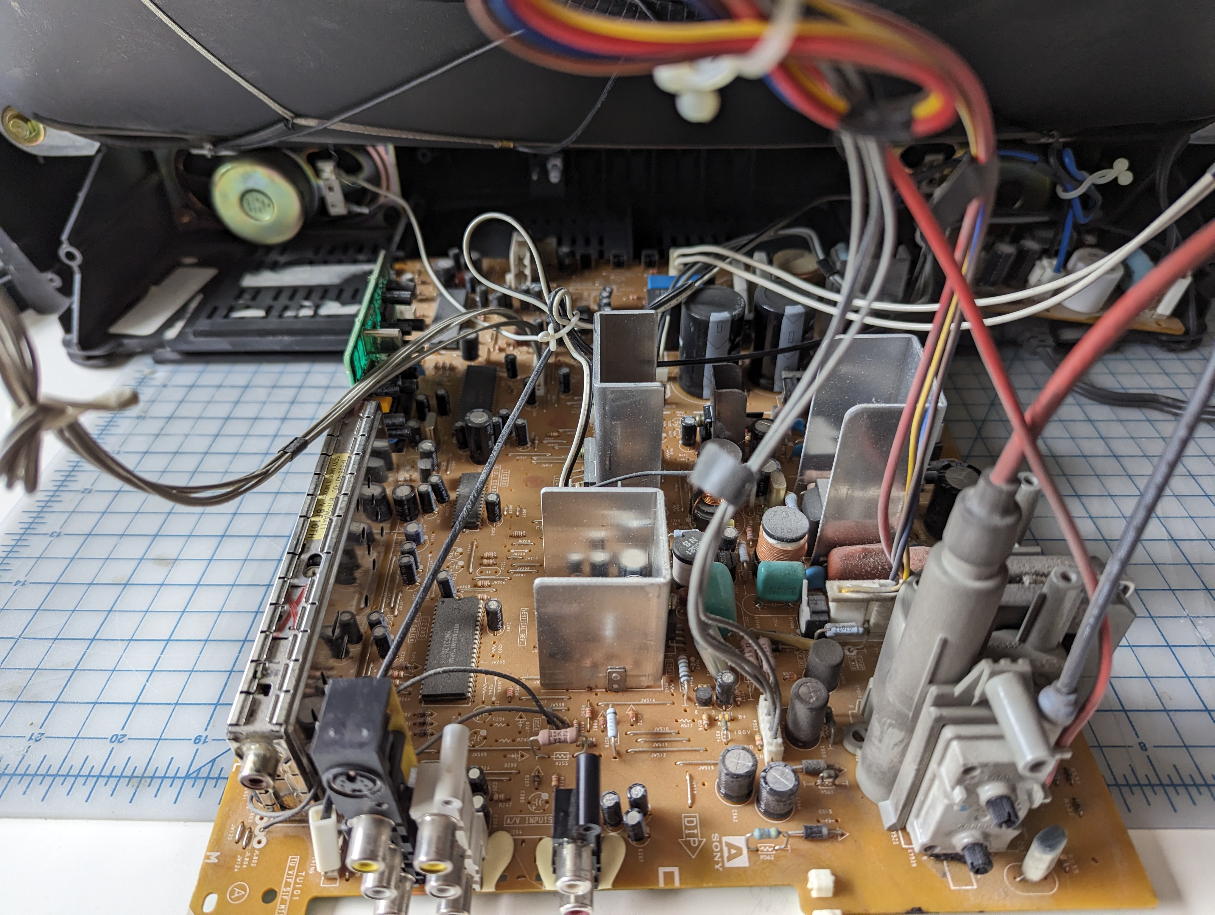
Yoke 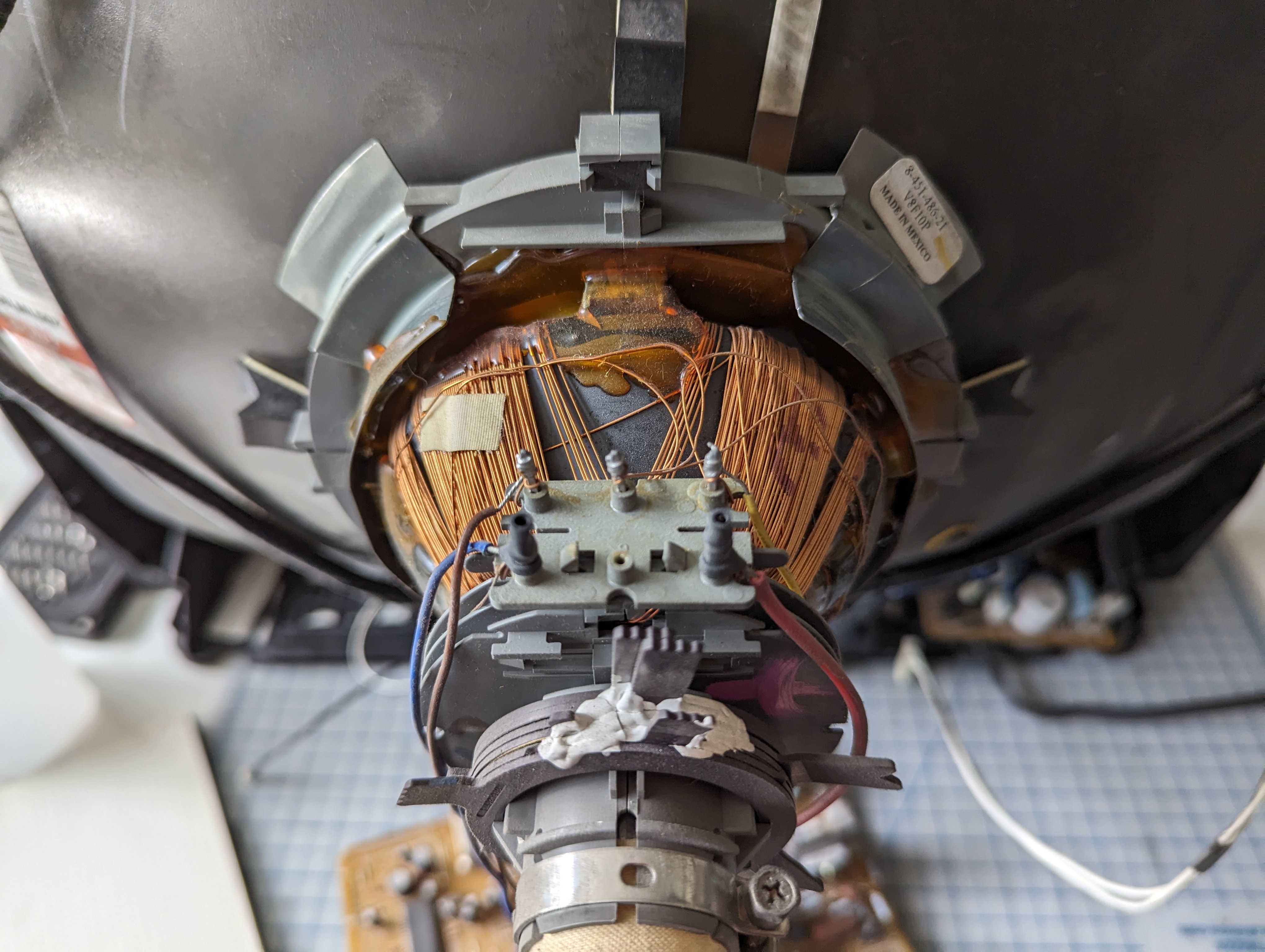
Neck Board 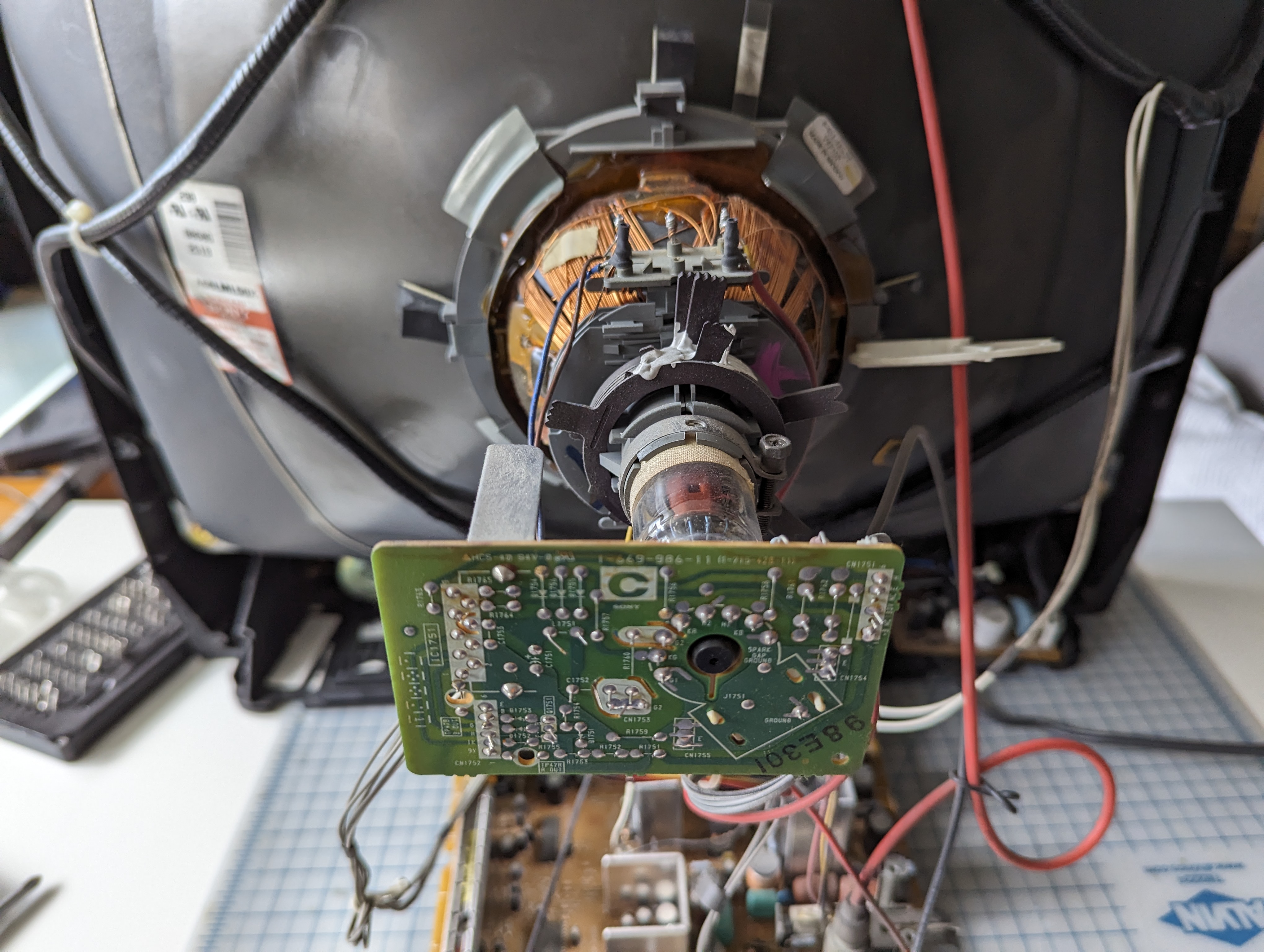
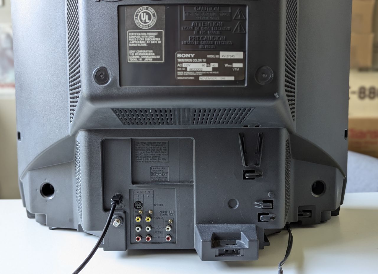
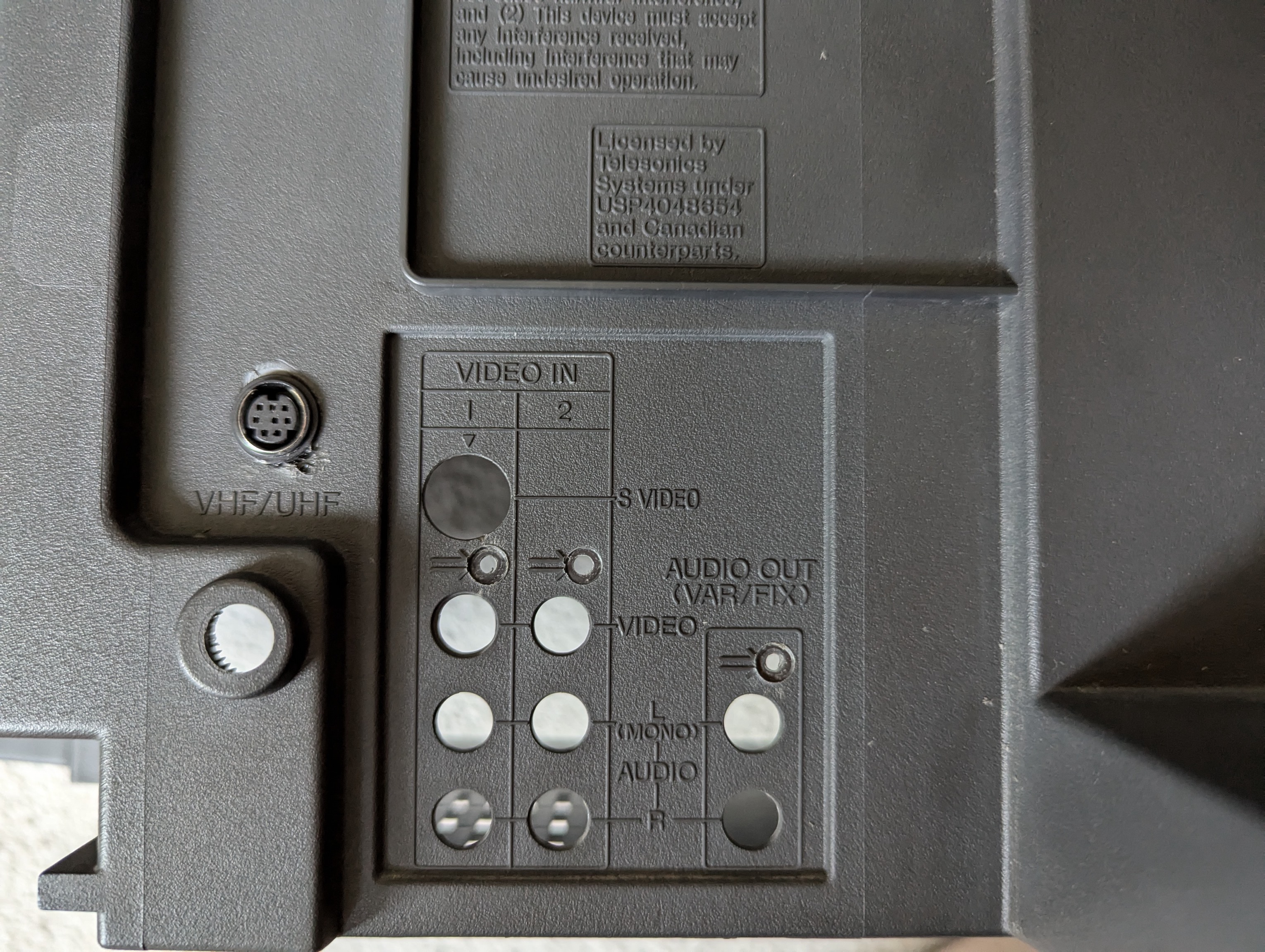
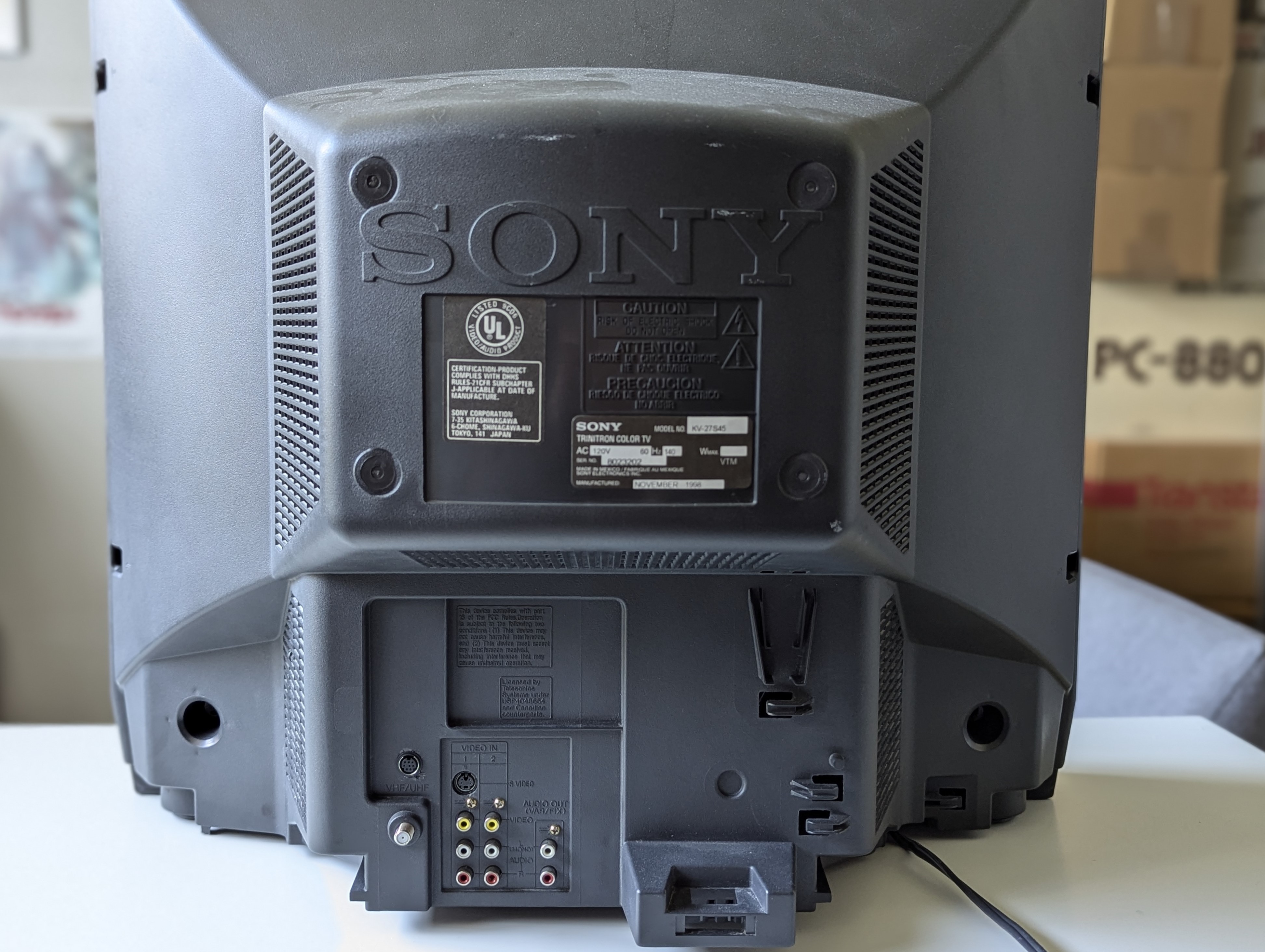
Back label 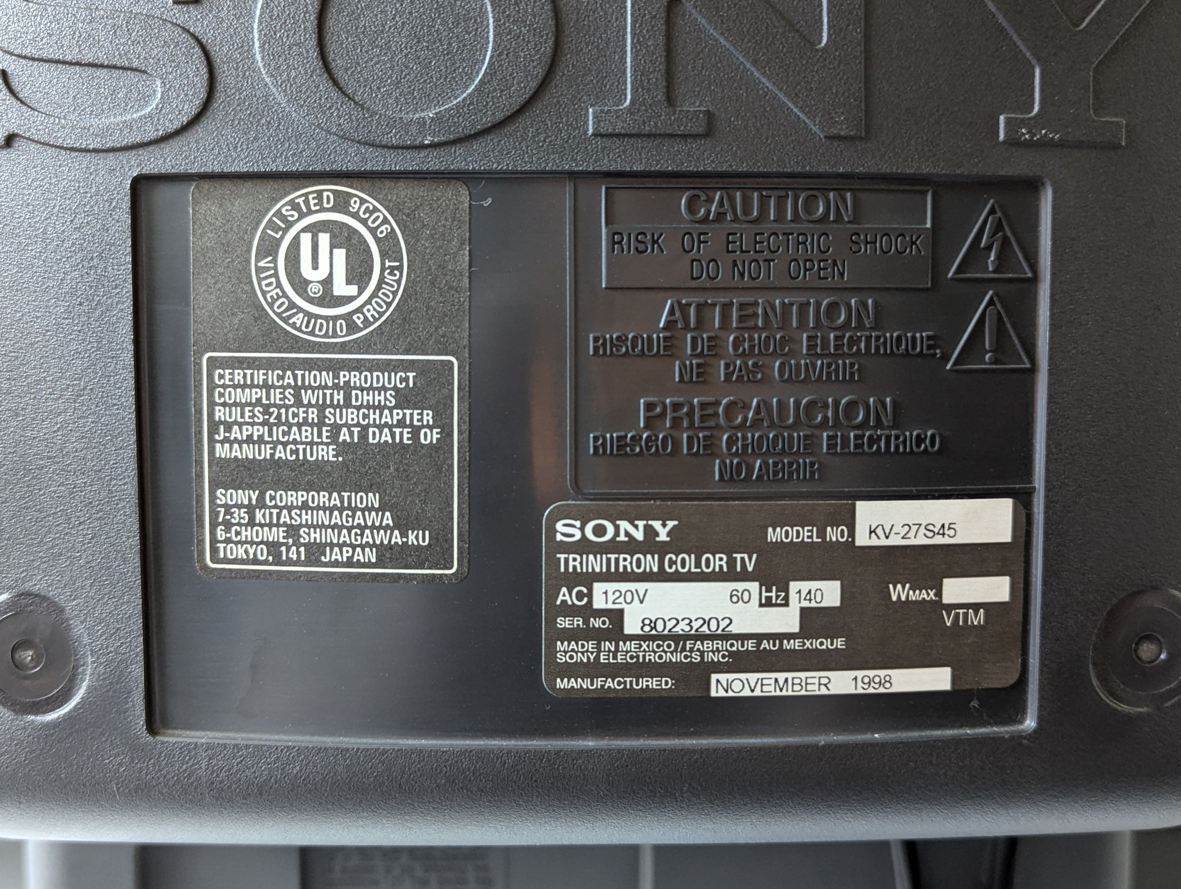
Tube
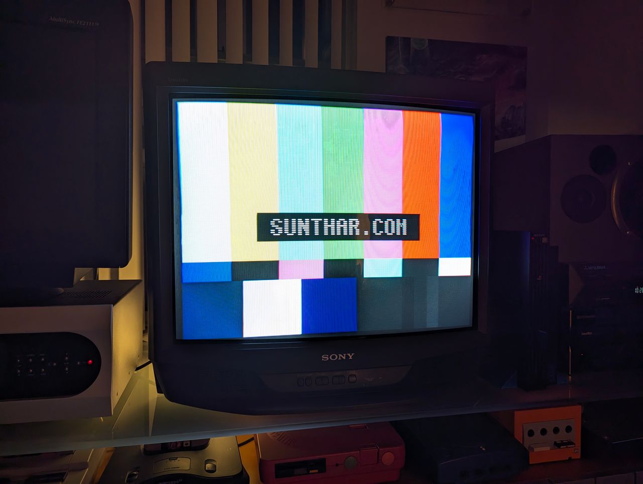
Set turned off 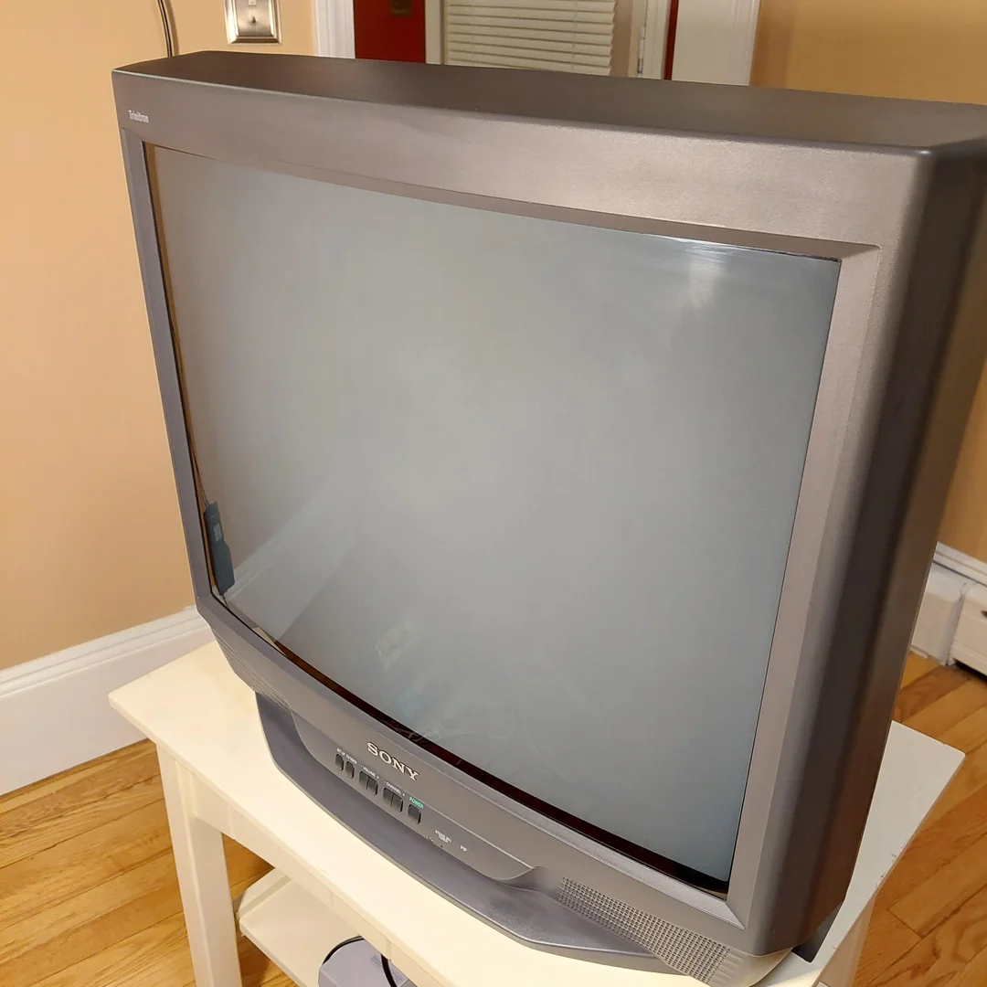
Pictures
Reference Photos