Sony (BA-4D)
Sony BA-4D chassis CRT RGB mod
If you have a BA-4D based CRT and want to modify it for RGB input, you'll find several tutorials linked from this page. Be sure to follow the tutorial specific to your model. While most BA-4/BA-4D based mods are generally similar, each tutorial may include unique insights or techniques that could enhance your final modification.
For example, the KV-20M40 tutorial explains how to use the remote control to switch between RGB and Component (YPbPr) inputs. Reviewing all the available tutorials before starting your modification is highly recommended to ensure the best possible outcome for your set.
There are also differences between the chassis used in 27" and larger models and those used in 20" and smaller models.
- KV-13M42
- KV-20M40 remote based switching
- KV-20M42
- KV-20S42
- KV-20S43
- KV-20S90
- KV-27V40
- KV-27S42 RGB
- KV-27S42 YPbPr
- KV-27S45
- KV-27V42
- KV-27S46
- KV-27S66
- KV-35S36
 Sony KV-20S42
 Sony KV-27S42
 Sony KV-27V42
CRT safety
Caution
You can die doing this! So read carefully! CRT TV is not a toy. Do not open a CRT TV. If you don't have any prior knowledge about handling high voltage devices, this guide is not for you. CRT TV contains high enough voltage (20,000+ V) and current to be deadly, even when it is turned off.
Plan of attack
Theory
Sometimes it is nice to know the theory behind the mod. I have put this on a separate page. This shows how the various resistor values are calculated.
Service manuals
- Sony KV-20S42 Service Manual
- Sony KV-20S90 Service Manual
- Sony KV-27S42 Service Manual
- Sony KV-27V42 Service Manual
Calculating the RGB external resistor value
Formula from our theory page!

Calcualted 910Ω for 0.7Vp-p. With didoe inline for RGB, you have to use 1kΩ
Follow the respective tutorials for the RGB modification
There are subtle differences between 20" and 27" BA-4D sets. For example, in the larger 27" models, you need to remove R086, whereas in smaller models, you need to remove R089. Additionally, smaller sets use the composite input for sync and are not significantly impacted by RGB shift. In contrast, larger sets require syncing through the luma input to minimize excessive RGB shift.
To achieve the best results, it’s recommended to follow the specific RGB mod tutorial for your model while incorporating helpful ideas from other BA-4D modification guides.
Tips
Later BA-4D 27" sets use a sync separator IC (IC010) for switching to the S-Video input, rather than the logic signal on the shield pins used in previous models. If the IC fails to properly recognize the signal, it loses sync. When I attempted to input RGBs from a Dreamcast with a DC2VGA DIY adapter in CSYNC mode to a KV-27V42 that I modded for a friend, it wouldn't sync unless I changed the ID-1 value to "23." This setting change reverts S-Video detection to the shield logic method instead of the sync separator method. You might want to try changing that setting to see if it resolves your issue.
On KV-27S66 service menu ID1 setting had to be changed from 155 to 23 in order for the s-video ground sensing to actually take effect. 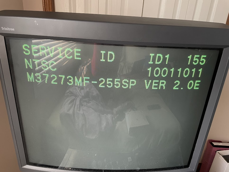
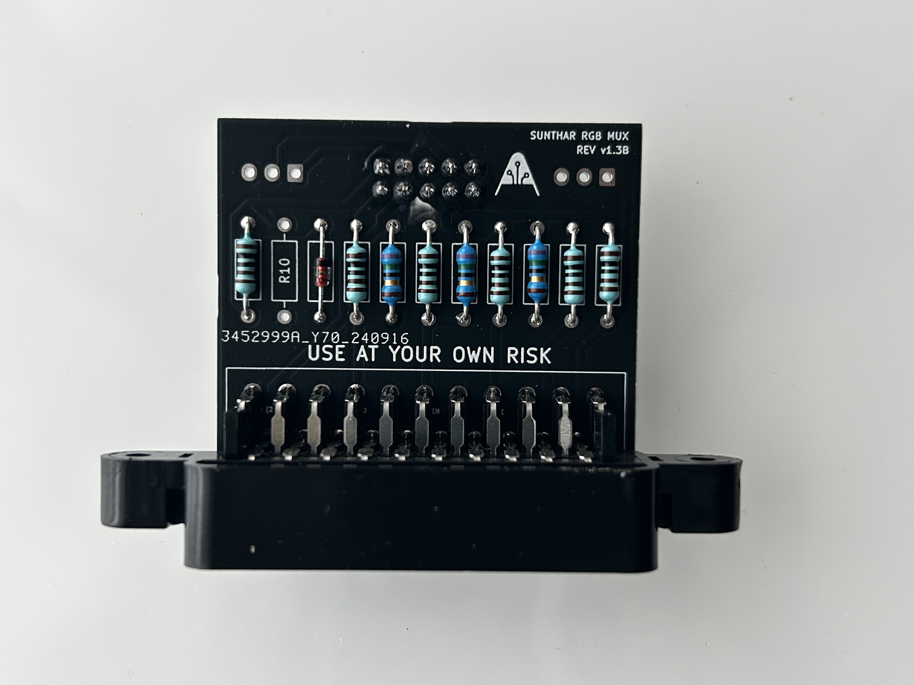
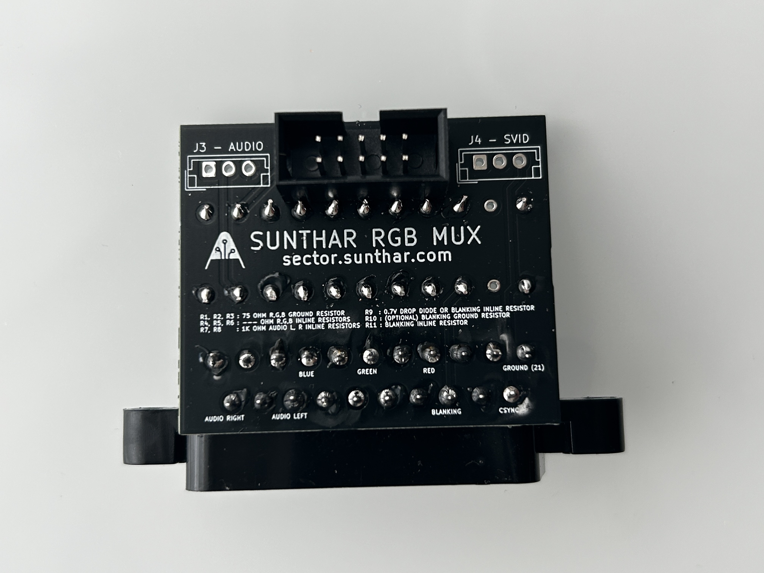
Sample mux board configuration
Below mod uses the RGB mux board. This is optional, but will make your mod easier and stable. You can also create the circuit presented in the schematics above without the board. Please also checkout the precalculated resistor values.
| TV Model | KV-20S40 | KV-20S90 | KV-20S42 | KV-27S42 |
|---|---|---|---|---|
| CRT inline resistors | 5.6kΩ | 5.6kΩ | 5.6kΩ | 5.6kΩ |
| Add diodes to RGB inline? | Yes | Yes | Yes | Yes |
| Add diodes to blanking on chassis? | No | No | No | No |
| RGB termination (R1, R2, R3) | 75Ω | 75Ω | 75Ω | 75Ω |
| RGB inline resistors (R4, R5, R6) | 1kΩ | 1kΩ | 1kΩ | 1kΩ |
| Audio LR (R7, R8) | 1kΩ | 1kΩ | 1kΩ | 1kΩ |
| Diode (R9) | 1N4148 | 1N4148 | 1N4148 | 1N4148 |
| Open (R10) | -- | -- | -- | -- |
| Blanking Resistor (R11) | 1kΩ | 1kΩ | 1kΩ | 1kΩ |
| Add diodes to RGB lines | Yes | Yes | Yes | Yes |
Attaching the female SCART connector to TV
Creating a SCART cutout and mounting it is an art. I have a dedicated section for it. How to create and mount a SCART female plug?
Depending on your CRT, you might need to find a good place to mount the SCART port.
Sony KV-20S42 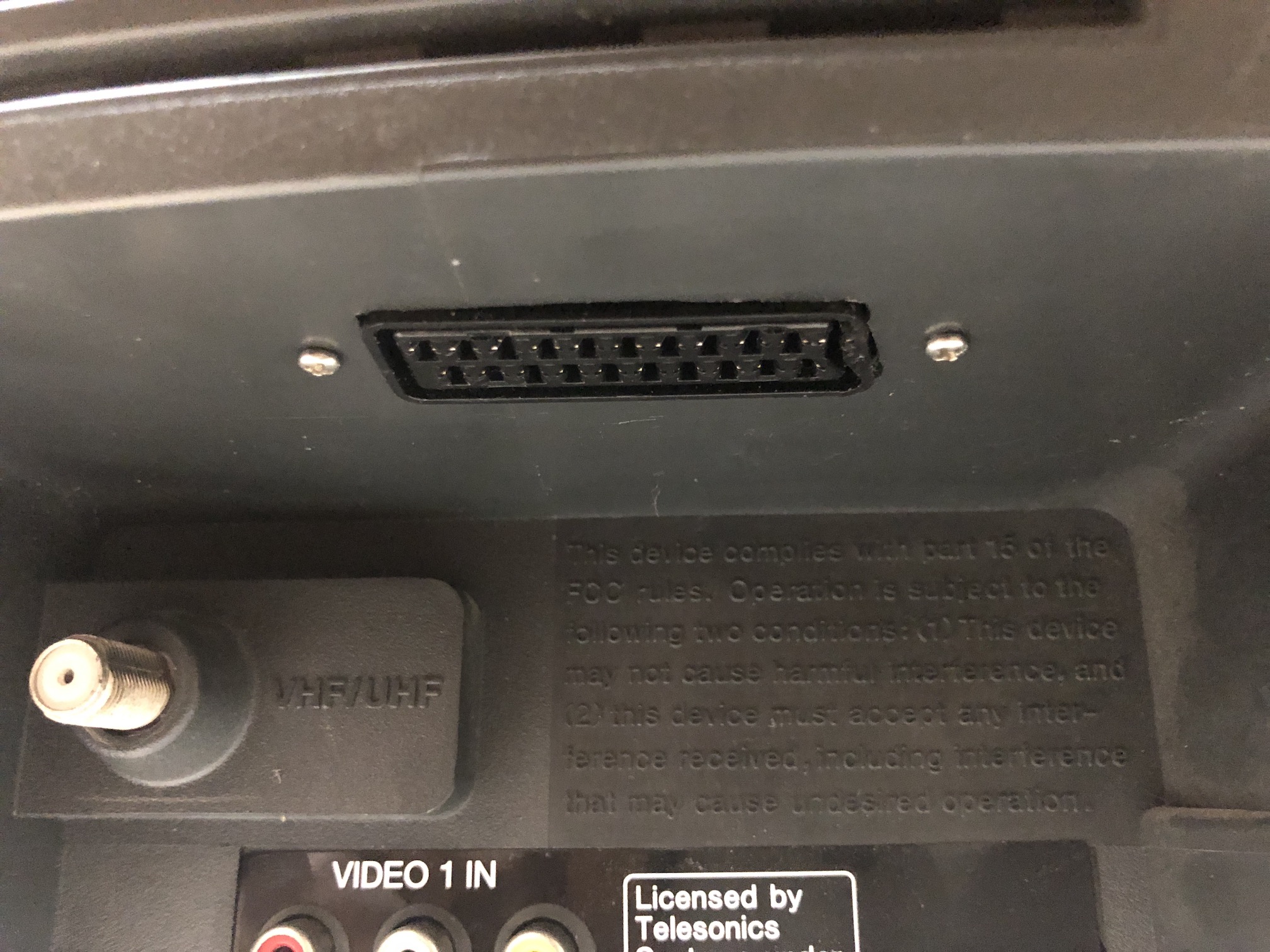
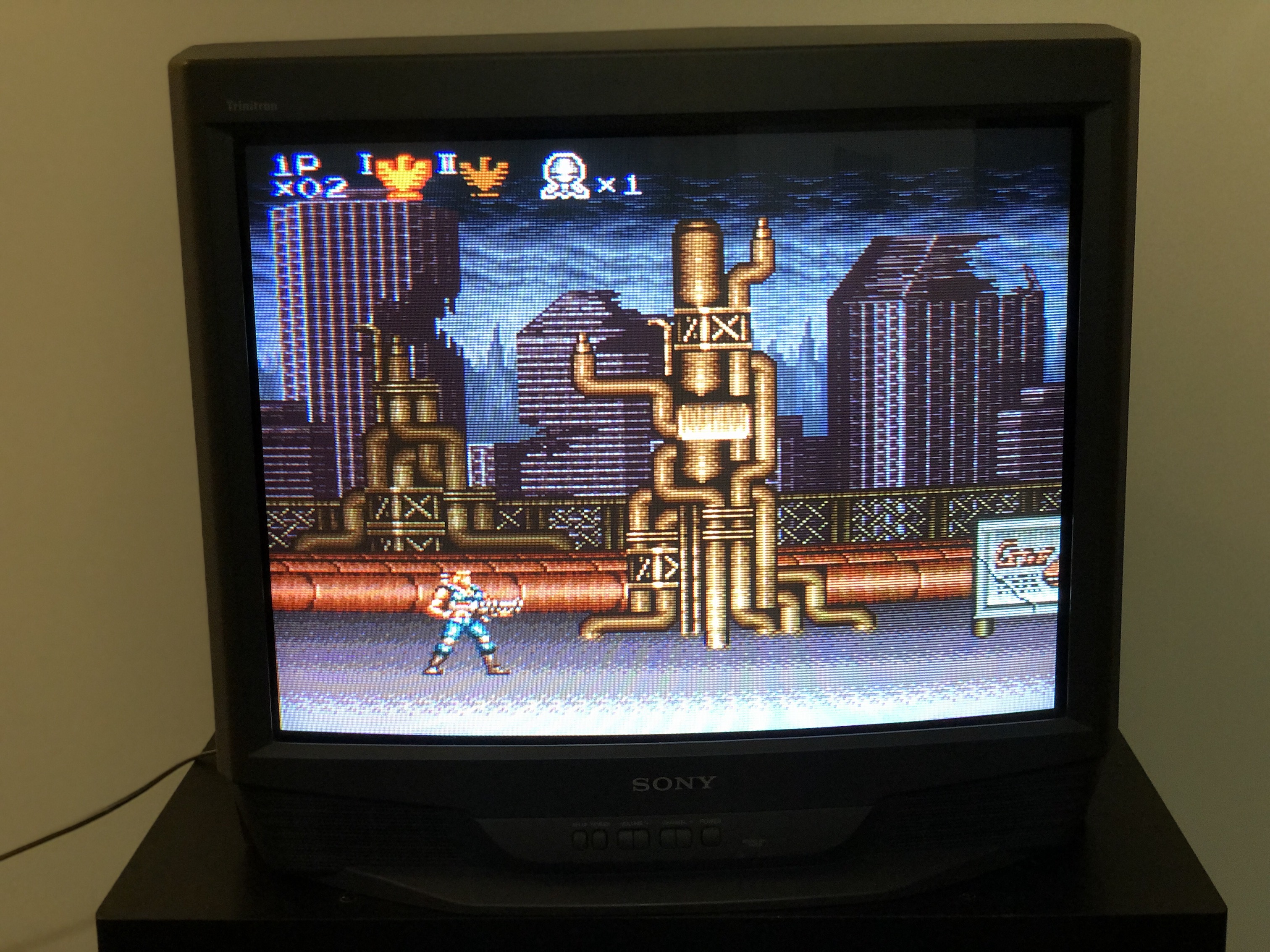
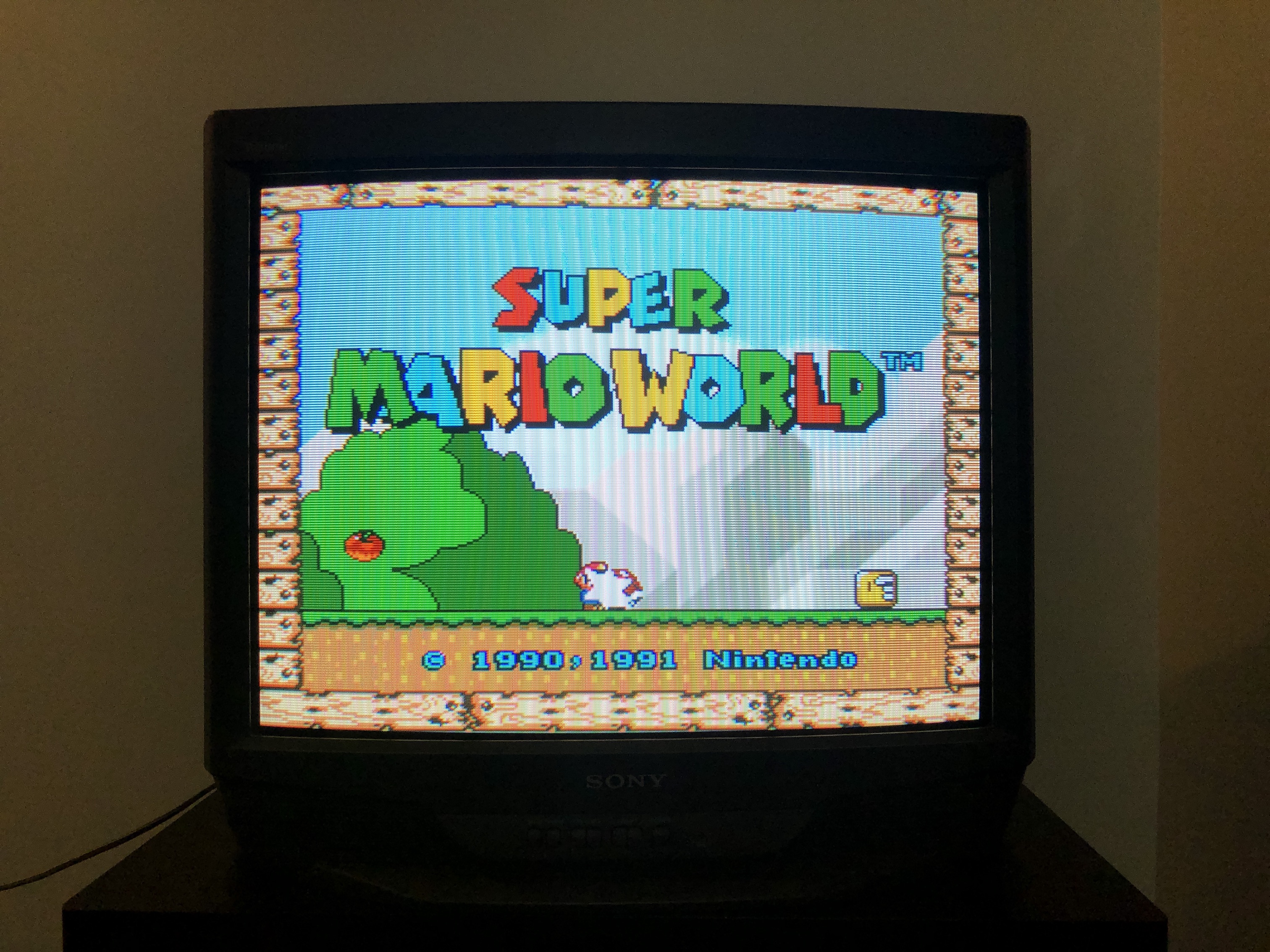
Sony KV-20S90 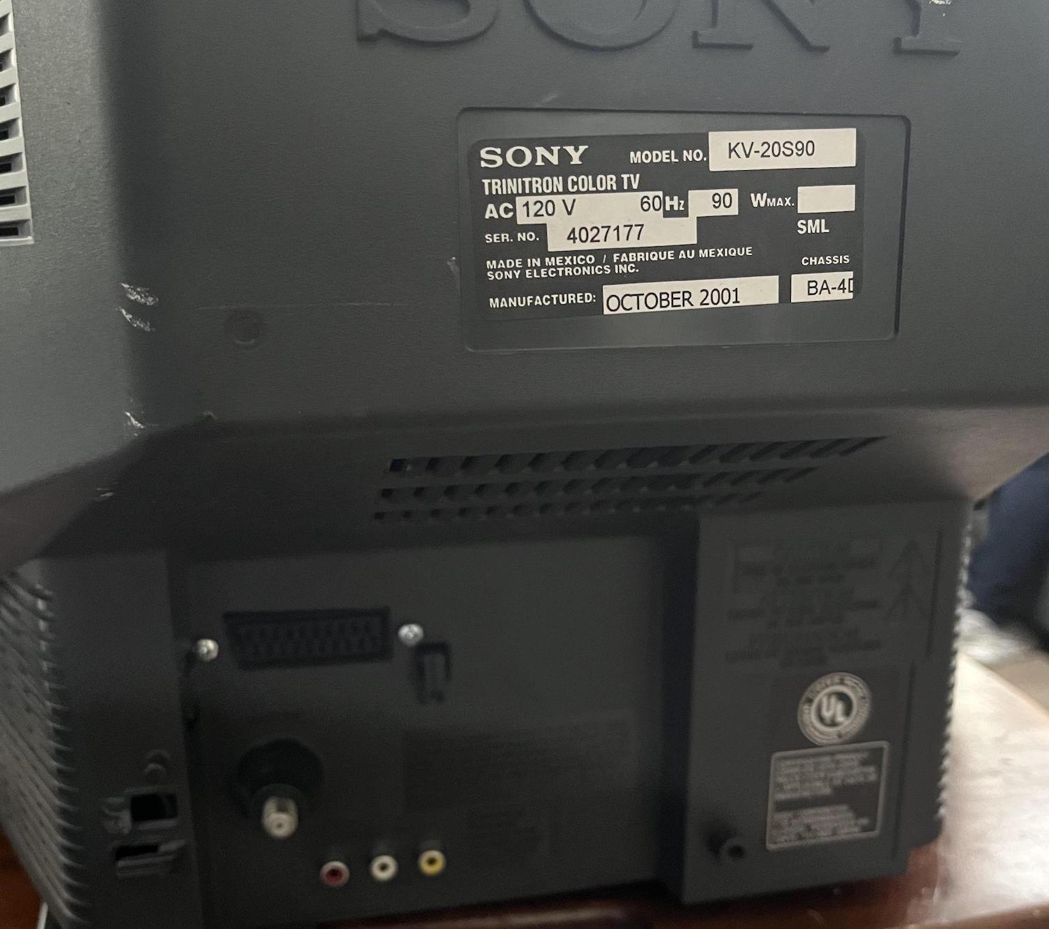
Sony KV-27S42 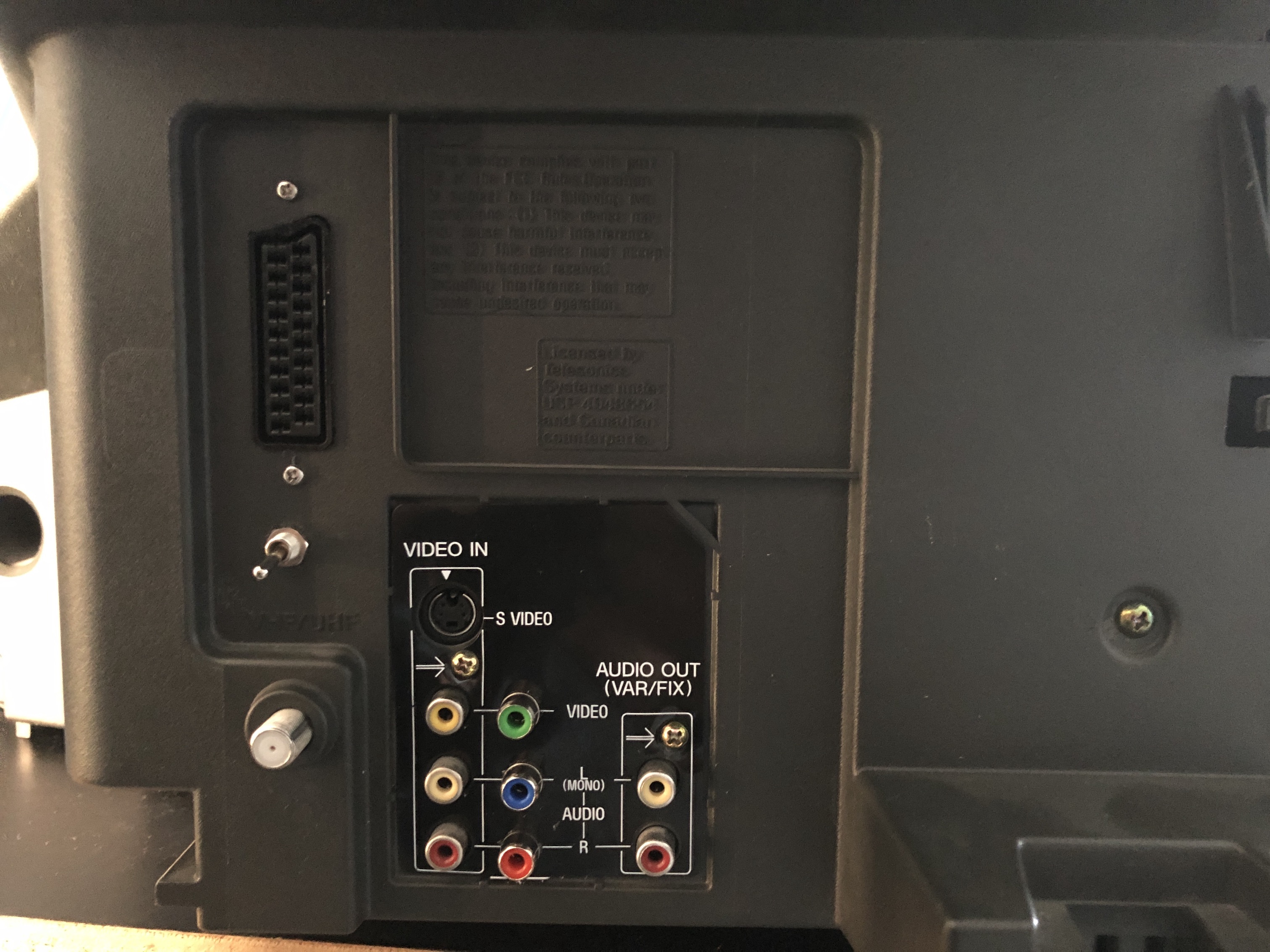
Reducing interference
Sometimes you might notice micro interference in the video signals. This is expected. To reduce it, try the following.
- Use diodes in-line for RGB signal
- Make sure your blanking wire is connected after the diode that feeds into the chroma chip (see diagram)
- Try routing most of the cabling below the PCB
- Keep the ribbon cable short
- I really didn't find any difference in interference in using shielded vs non-shileded cables. Therefore, this is optional.
Getting into the service menu
- Turn the set on and then put into standby
- Press the
Display,5,VOL +buttons in sequence - Turn on the CRT and you should be in service mode
- Use buttons "1" and "4" on the remote control to navigate the service menu
- Use buttons "3" and "6" to adjust the selected data
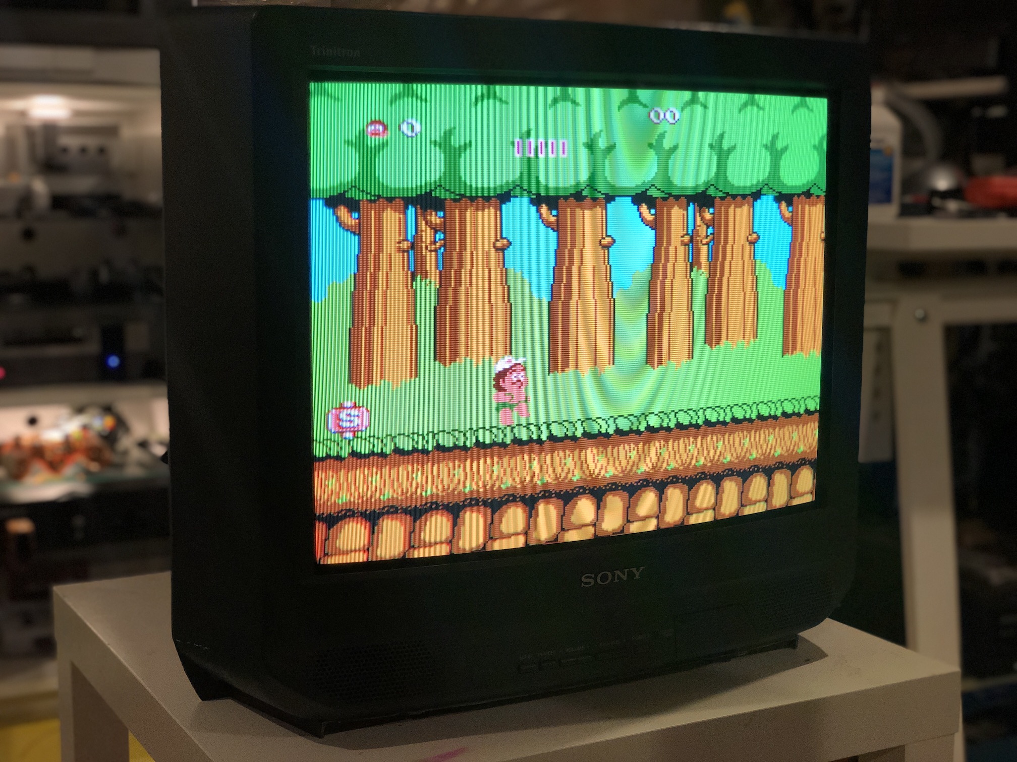
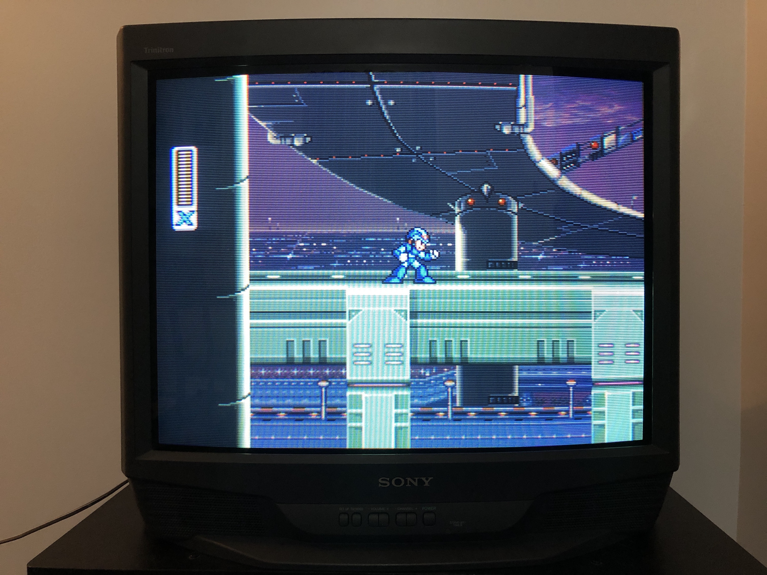
Games (KV-27S42)
Patterns (KV-27S42)
Monoscope - KV-27S42 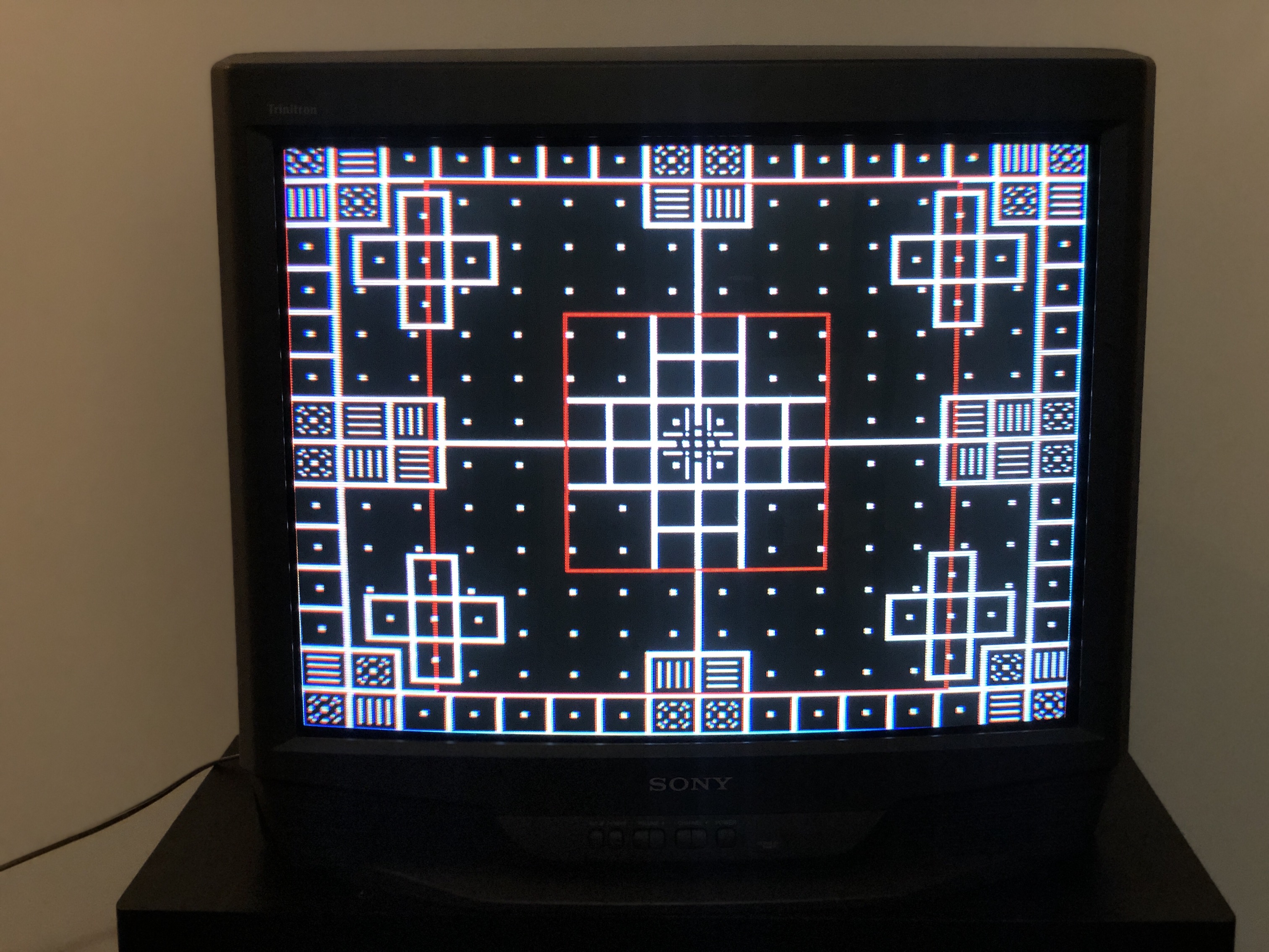
SMPTE - KV-27S42 (angle shot) 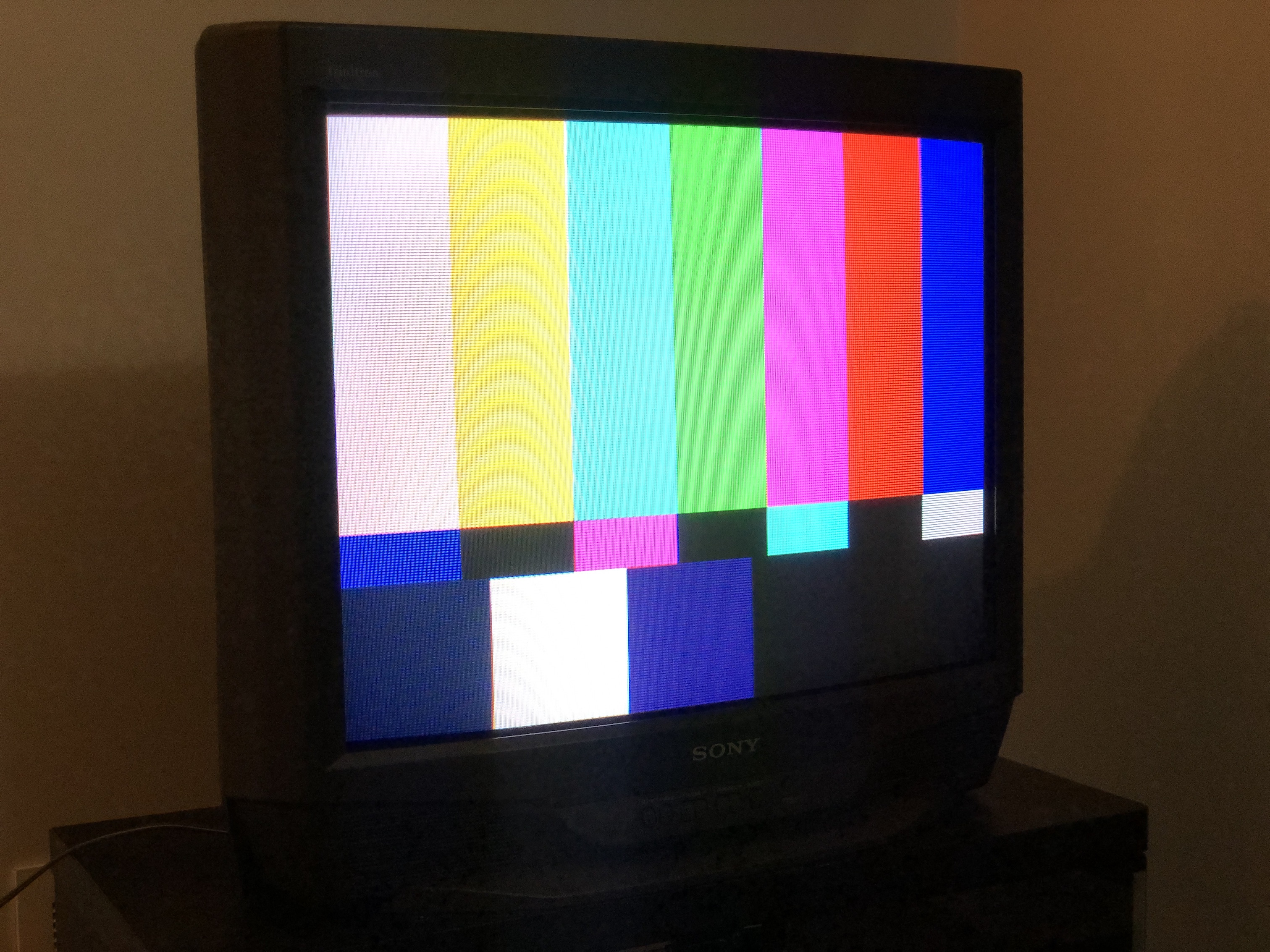
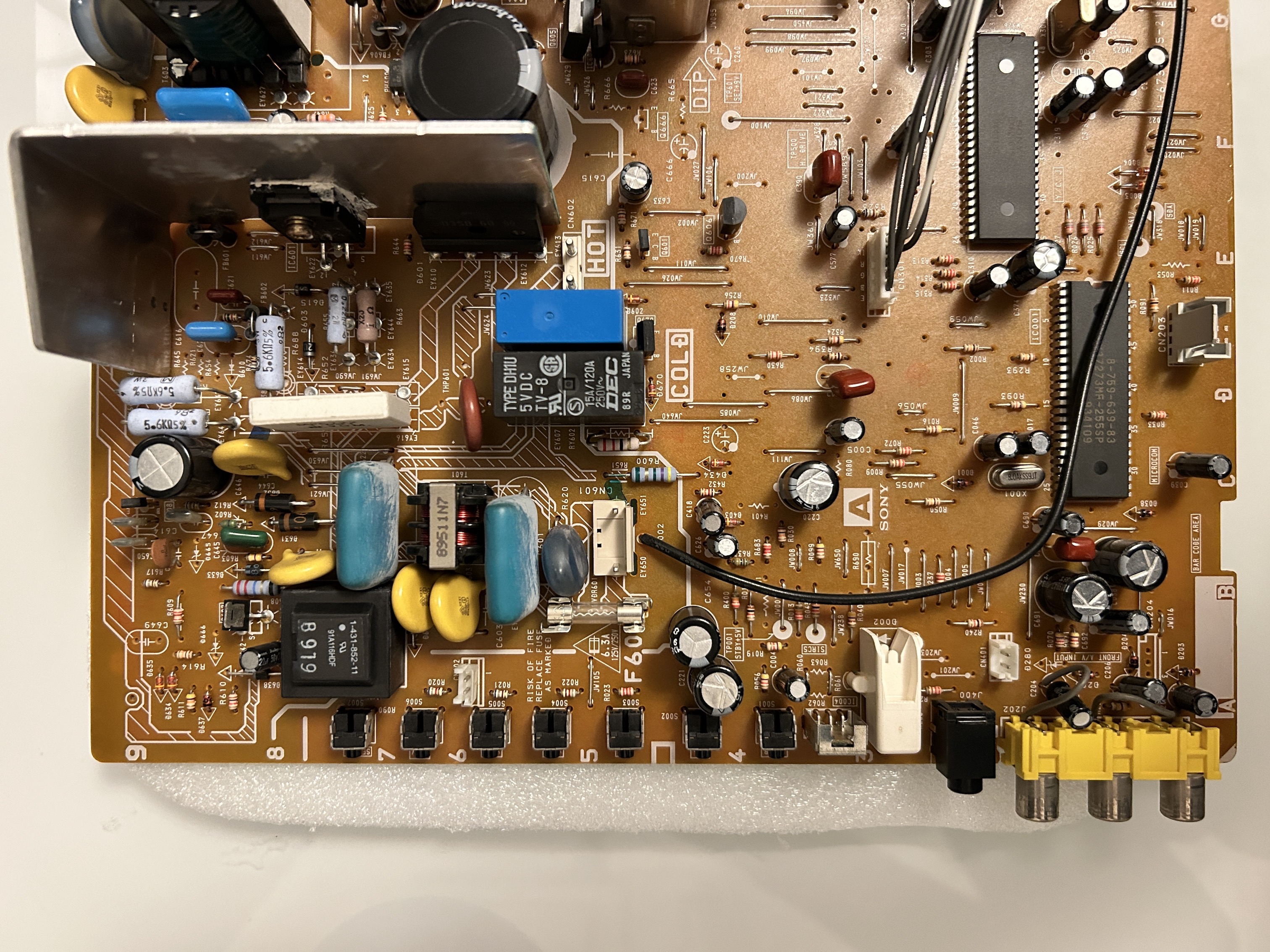
CRT Chassis (KV-27S42)
Board - component side