JVC AV-36850
JVC AV-36850 CRT RGB mod
The JVC AV-36850 is a 36", high quality consumer CRT from roughly 1997, acting as a direct precursor to the famed D-Series. While it natively lacks component video (offering only composite and S-Video), it is highly prized by enthusiasts for its excellent picture quality, often requiring an RGB mod to unlock its full potential.
View full CRT details and more mod examples →
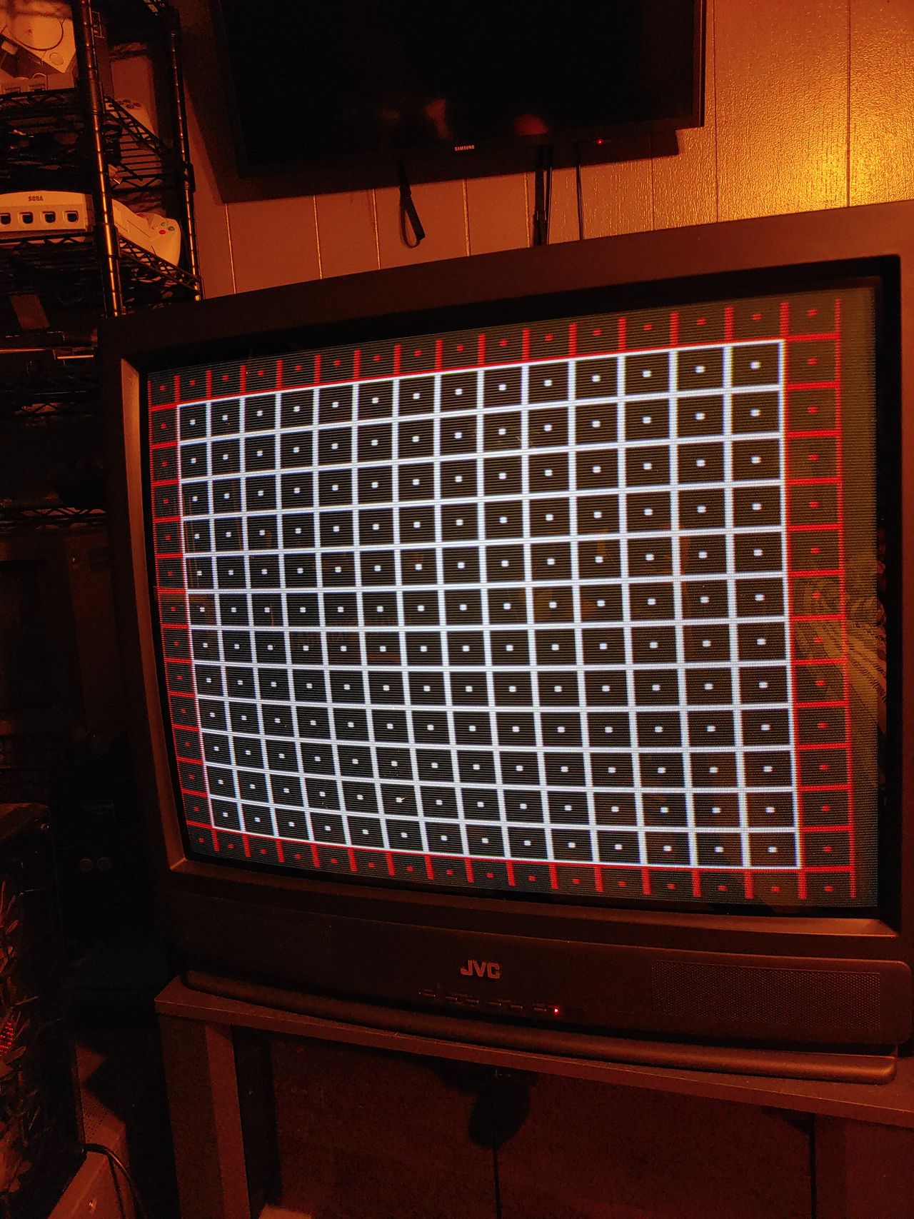
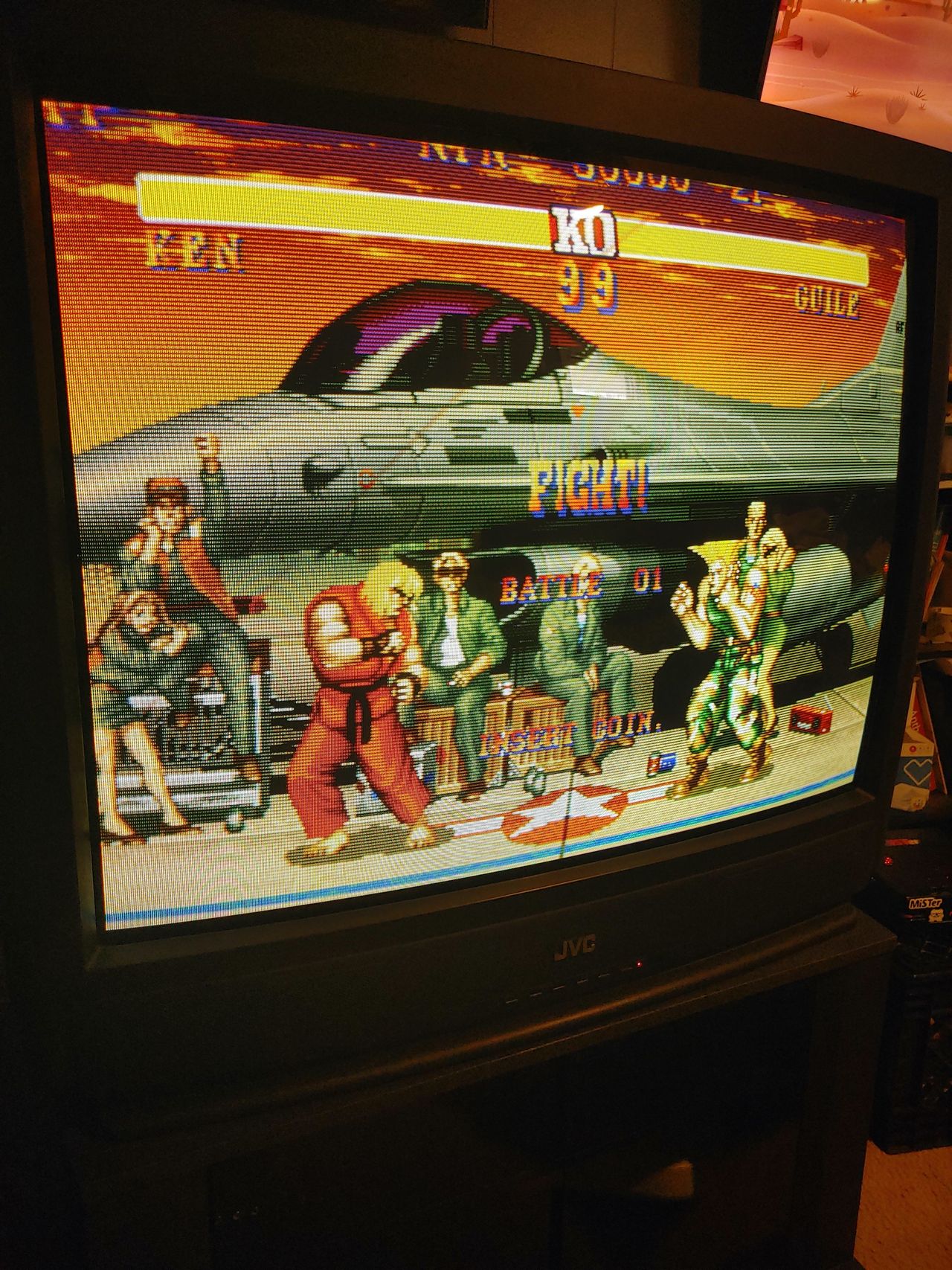
This crt originally had composite and s-video only, its from 97 right before the D series .... The TA1242N jungle chip used on these CRTs were kind of a mystery. The chips data sheet is in Japanese and it was assumed from it that the jungle needed 0.5Vp-p rgb signals. Mark on shmups held my hand again through this one. We attenuated the signal to 0.5Vp-p and it was super dim. No amount of RGB levels or cutoff adjustment helped.
I was bummed out and thought I fried something when I turned the G2 (flyback brightness/screen) up too high to try and brighten the image.
Mark said he heard these chips needed 1Vp-p but it was basically unknown
Due to how dim 0.5Vp-p was I skipped 0.7Vp-p which is the SCART standard and went for 1Vp-p by removing attenuation resistors, using 180 ohm termination, and swapped mux resistors to 510 ohm. It came out perfect!
A tiny tweak to the G2 was all that was needed.
I own a dozen or so pvm/pro/ broadcast monitors and this tube here is now one of my favorite tubes! It was a pain to pick up, haul upstairs, recap, clean, and mod twice but glad I stuck with it! It was definitely worth the troubles!!!
Contributors
Thank you to everyone who contributed to this guide:
- deezdrama — author, RGB mod and pictures
CRT safety
Caution
You can die doing this! So read carefully! CRT TV is not a toy. Do not open a CRT TV. If you don't have any prior knowledge about handling high voltage devices, this guide is not for you. CRT TV contains high enough voltage (20,000+ V) and current to be deadly, even when it is turned off.
Plan of attack
Manuals and Datasheets
Specs
- Year:
- Format: NTSC
- Chassis: GV2
- Tube: Hitachi A80LJF30X
- Jungle Chip: Toshiba TA1242N
- OSD Chip: Matsushita MN1874878JP1
- Screen Size: 36"
- Inputs: Composite, S-Video, RF
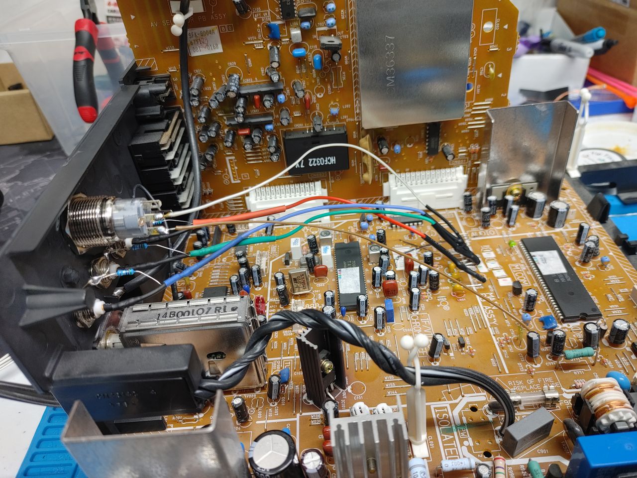
RGB mux diagram
RGB 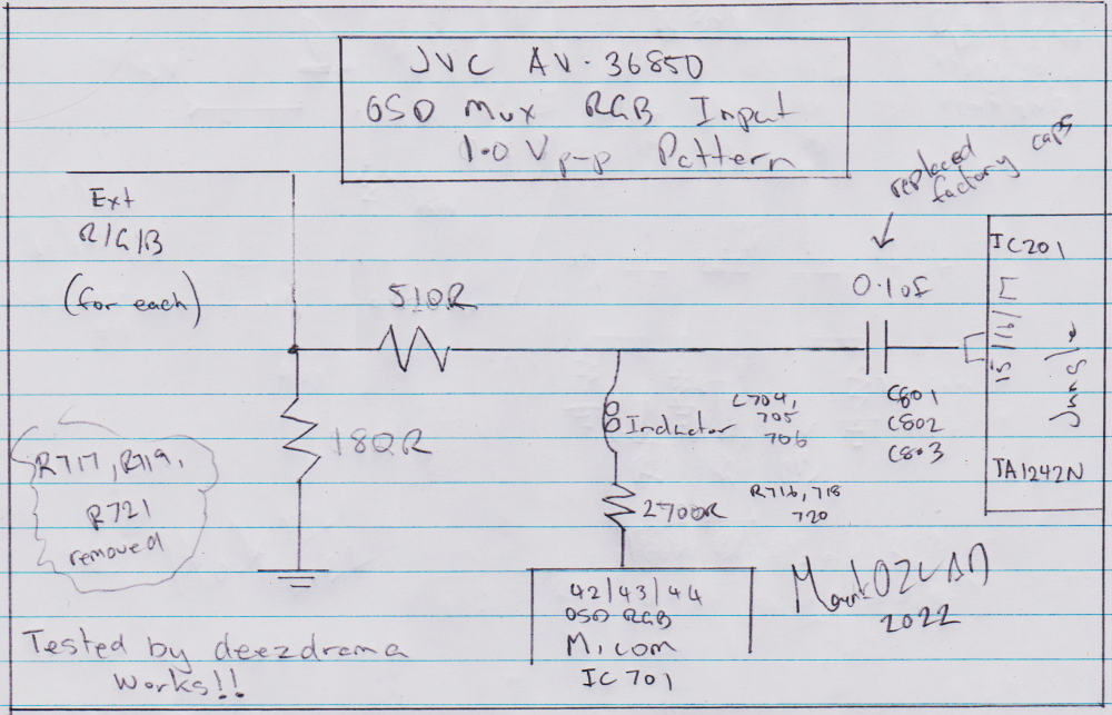
Blanking ![]()
Performing the mod
Thanks to MarkOZLAD/deezdrama
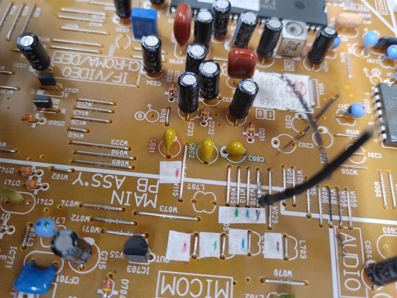
- Remove SMD resistors R717, R719, R721 (factory OSD "grounding" resistors)
- For blanking we want to go from a 5V source into a switch then into a 1.8K resistor and then onto jumper W019
- For each of the RGB lines we want to bring in the external RGB, we want 180 ohm to ground. Then for each run a line from between these two resistors onto the RGB jumpers into a 510 ohm resistor then onto their respective jumpers.
- Replace caps C801, 802 and 803 with 0.1uF (104) ceramic caps
- Sync into factory AV port (composite or svideo luma, even component Y)
This is the way.
This mod uses the RGB mux board. This is optional, but will make your mod easier and stable. You can also create the circuit presented in the schematics above without the board. Please also checkout the mux calculator to play with your own values.
| Component | Value |
|---|---|
| RGB/OSD inline resistor (chassis) | 2.2kΩ |
| Removed RGB/OSD resistor (chassis) | 470Ω |
| RGB inline diode method (chassis) | Yes |
| 0.1μF caps replaced (chassis) | Yes |
| RGB termination (R1, R2, R3) | 220Ω |
| RGB inline (R4, R5, R6) | 470Ω |
| Audio LR (R7, R8) | 1kΩ |
| Diode (R9) | 1N4148 |
| Blanking Ground Resistor (R10) | open |
| Blanking Resistor (R11) | 1kΩ |
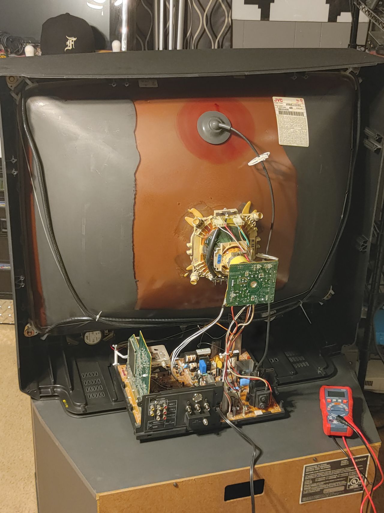
Pictures
Reference Photos