Toshiba 13A22
Toshiba 13A22 CRT RGB mod
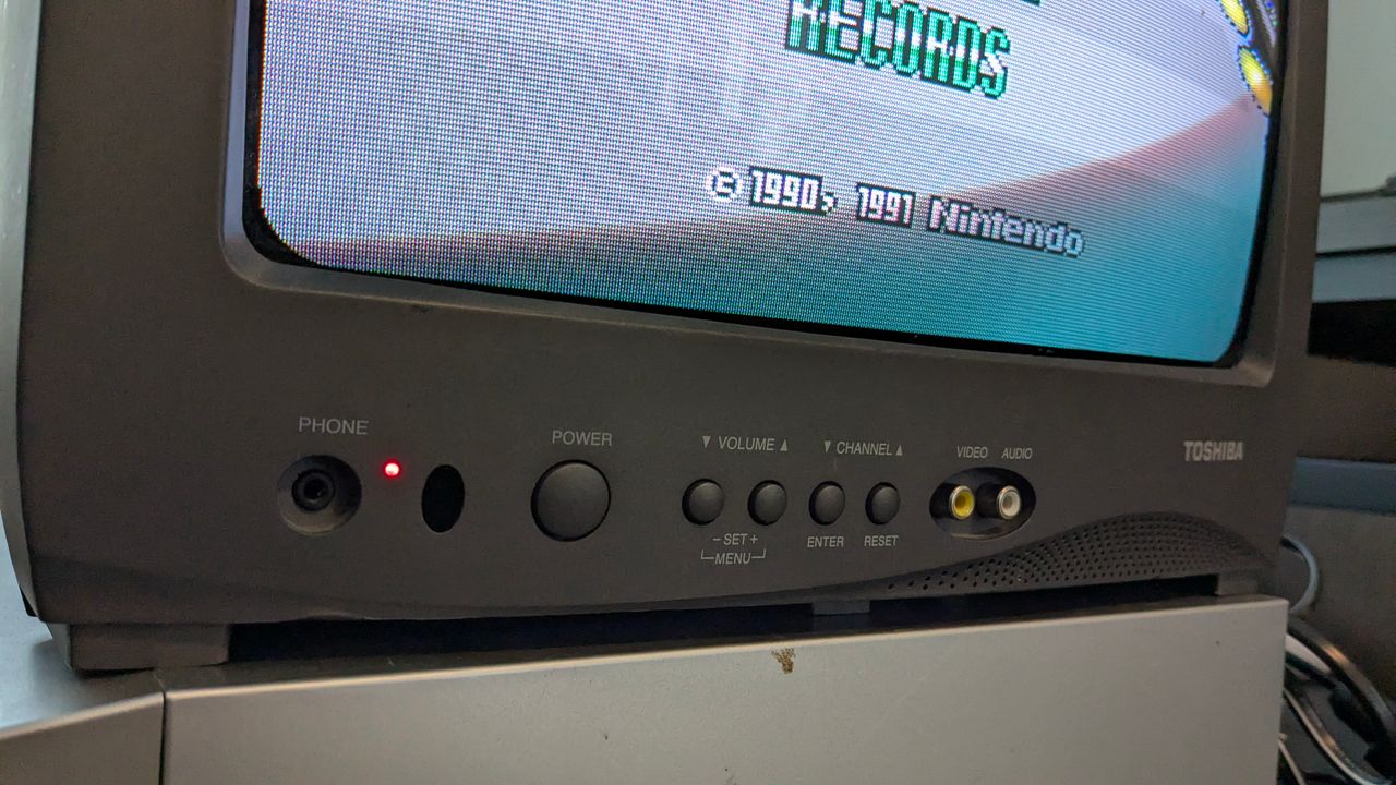
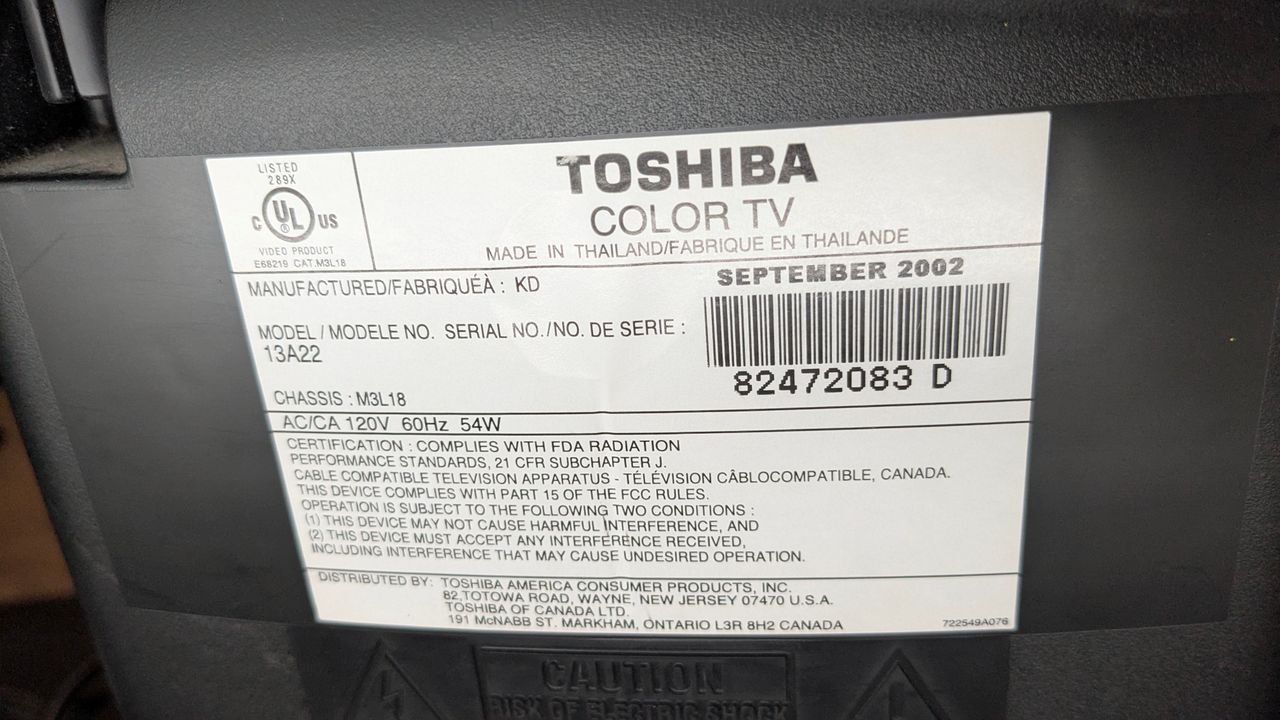
The Toshiba 13A22 is a 13" CRT display that can be easily modified for RGB input. Although it carries the Toshiba name, it was actually manufactured by Orion.
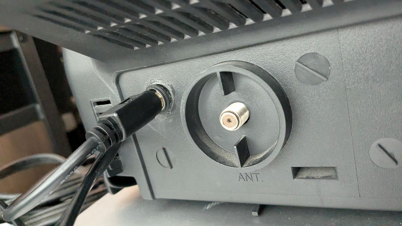
The set includes front-facing RCA inputs and an RF connector on the back.
I’ve only encountered this model in a dark grey finish. While aesthetics are subjective, I find this CRT more visually appealing than many other Orion-produced sets.
Sansui TVM1316B uses the same chassis and is also RGB moddable.
View full CRT details and more mod examples →

This RGB mod should also apply for the below model
Also check the mod for Toshiba 13A21. It uses a different chassis than Toshbia 13A22.
This mod doesn't work for the below models. Below models use a single-chip. In the absence of OSD chip, RGB mod is not possible.
- Toshiba 13A23
- Toshiba 13A24
- Toshiba 13A25
Contributors
Thank you to everyone who contributed to this guide:
- Brent's Sector — showcase author, contributor, RGB mod and pictures
- Jake G's Sector — contributor, Contributed to this entry
- Sunthar — author, RGB mod article
CRT safety
Caution
You can die doing this! So read carefully! CRT TV is not a toy. Do not open a CRT TV. If you don't have any prior knowledge about handling high voltage devices, this guide is not for you. CRT TV contains high enough voltage (20,000+ V) and current to be deadly, even when it is turned off.
Plan of attack
Manuals and Datasheets
Specs
- Chassis: M3L18
- Jungle Chip: Renesas M61250FP
- OSD Chip: Orion OEC7072A
- Screen Size: 13"
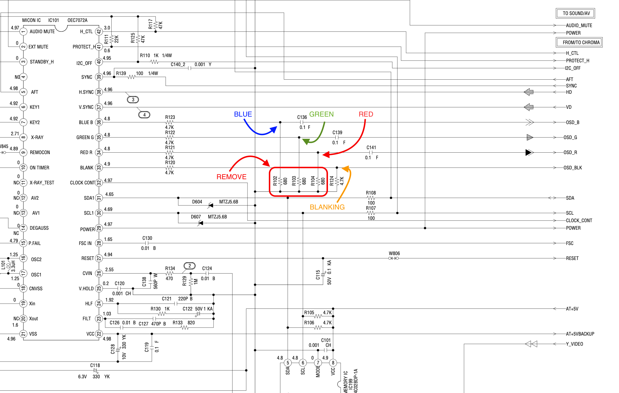
Schematics
Get hold of the schematics for your TV. Understand where the RGB and Fast Blanking signals go from OSD to the Jungle (Chroma) chip.
RGB mux diagram
Prepare the mux diagram. If you are building your own circuit, this diagram should help.
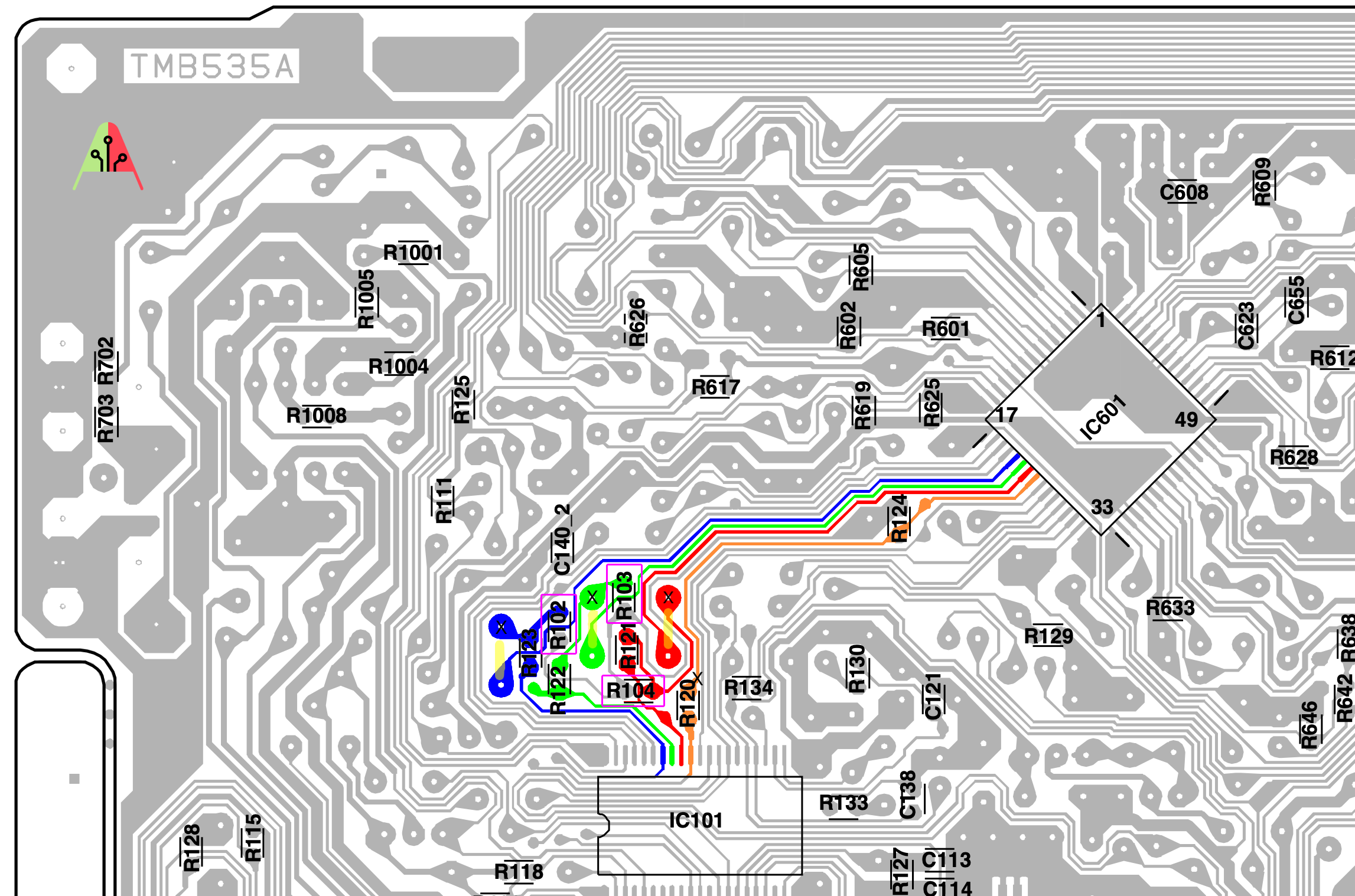
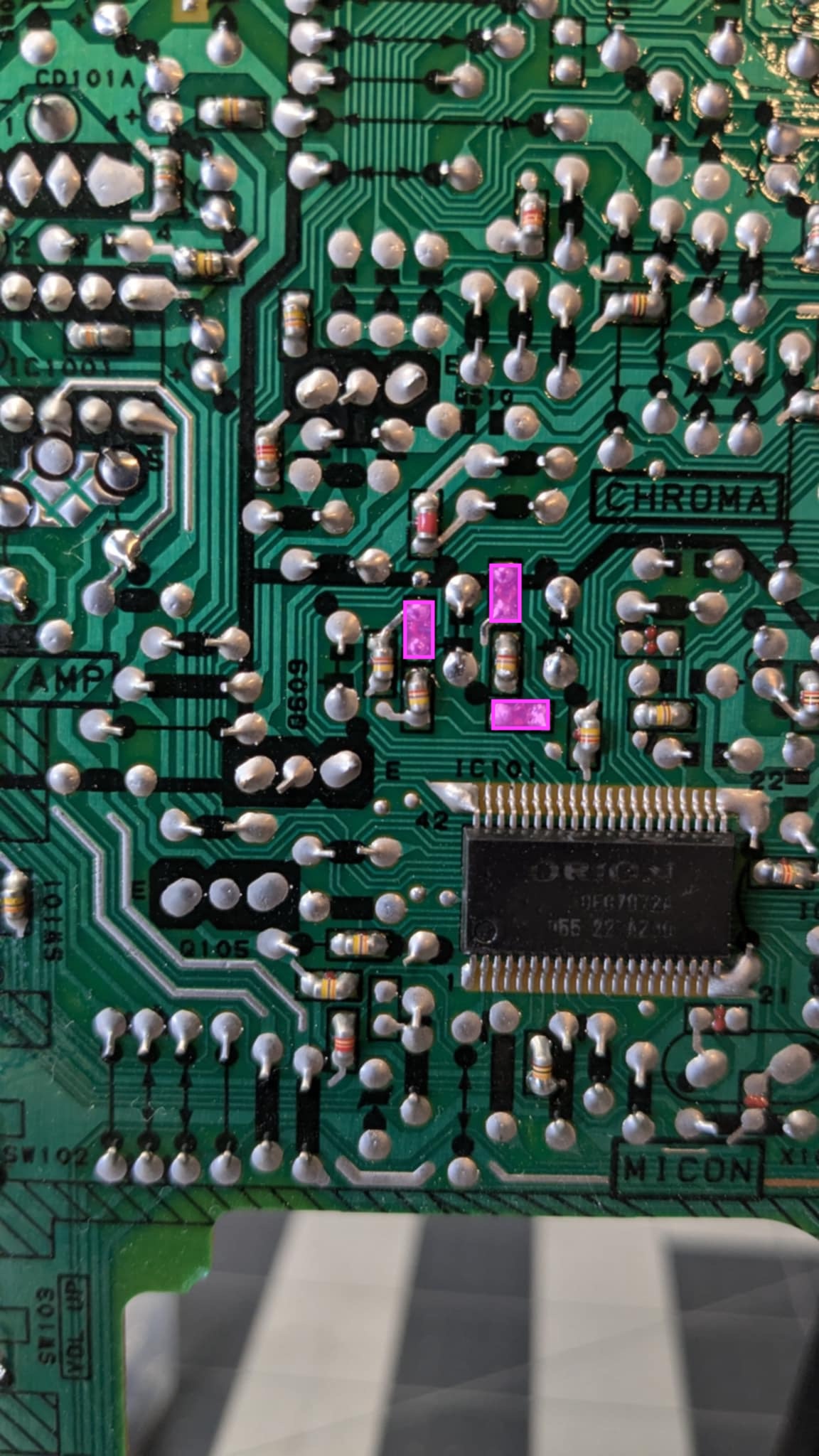
PCB
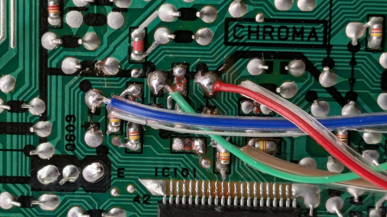
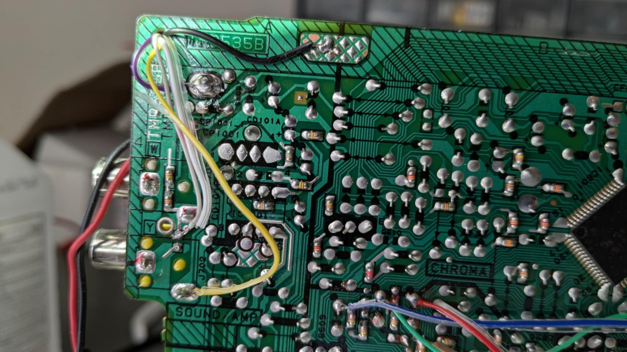
Points where the R, G, B and Blanking (brown) wires should be connected are marked "X". Pink boxes show the resistors that needs to be removed.
Performing the mod
STEP 1: Remove the following components
Remove the three 680 ohm, RGB resistors to ground
- R102
- R103
- R104
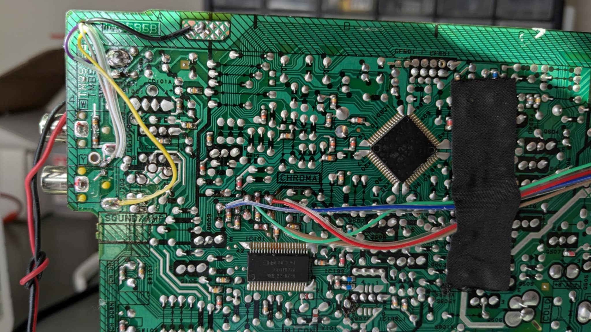
STEP 2: Connect R, G, B and blanking wires
RGB and blanking wires ![]()
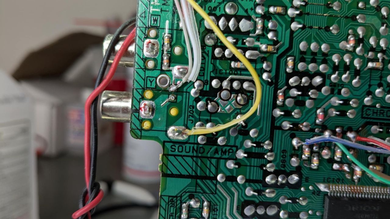
STEP 3: Connect sync, audio and ground wires
This set only supports mono audio. Therefore you would twist both grey and white wires together and solder it to the mono audio input. 1 kΩ resistors on the mux board will handle the channel mixing.
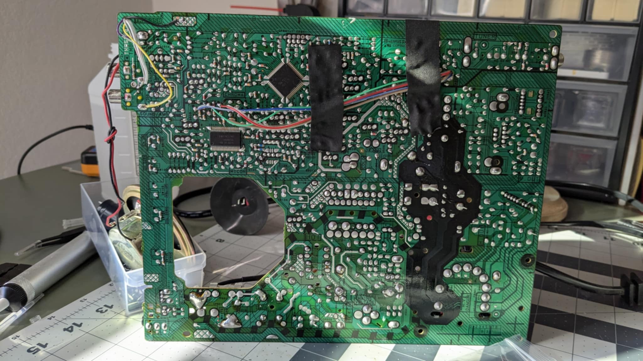
STEP 4: Wire routing and full mod
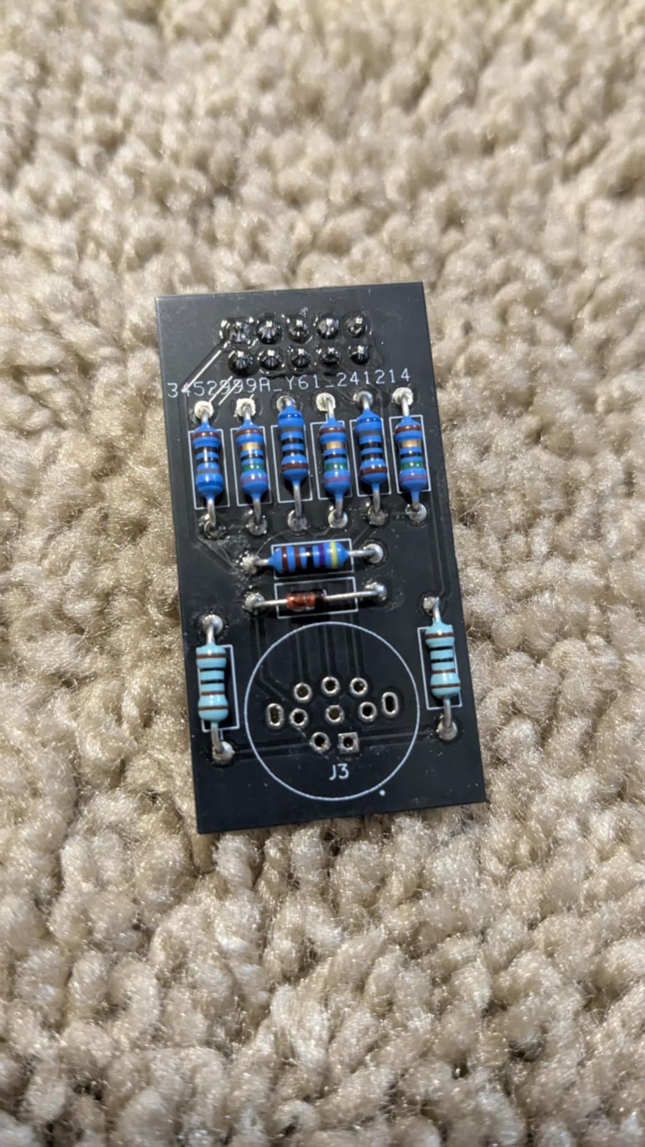
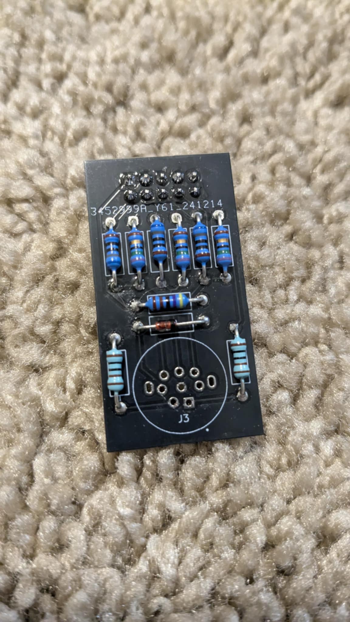
STEP 3: Build your mux circuit
This mod uses the RGB mux board. This is optional, but will make your mod easier and stable. You can also create the circuit presented in the schematics above without the board. Please also checkout the mux calculator to play with your own values.
| On Toshiba CRT Chassis | 13A22 |
|---|---|
| CRT RGB inline resistor | 4.7kΩ |
| CRT RGB ground resistors removed | 680Ω |
| 0.1μF caps replaced | No |
| Add diodes on chassis RGB lines? | No |
| Add blanking diode on chassis | No |
| RGB mux board | 13A22 |
|---|---|
| Mux board RGB termination (R1, R2, R3) | 75Ω |
| Mux board RGB inline resistors (R4, R5, R6) | 680Ω |
| Mux board Audio LR (R7, R8) | 1kΩ |
| Mux board blanking diode (R9) | 1N4148 |
| Mux board blanking ground resistor (R10) | open |
| Mux board blanking resistor (R11) | 4.7kΩ |
Compatible mux boards:
Highly recommended to use the variant B of the board or the micro board. Both should work well on this set. Mini mux board variant "B" installation requires a bit more precise planning. See pictures from this page to get an idea.
STEP 4: Attach the female SCART connector to TV
Creating a SCART cutout and mounting it is an art. I have a dedicated section for it.
How to create and mount a SCART female plug?
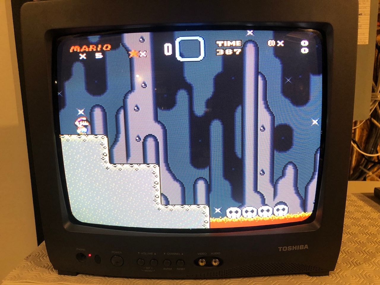
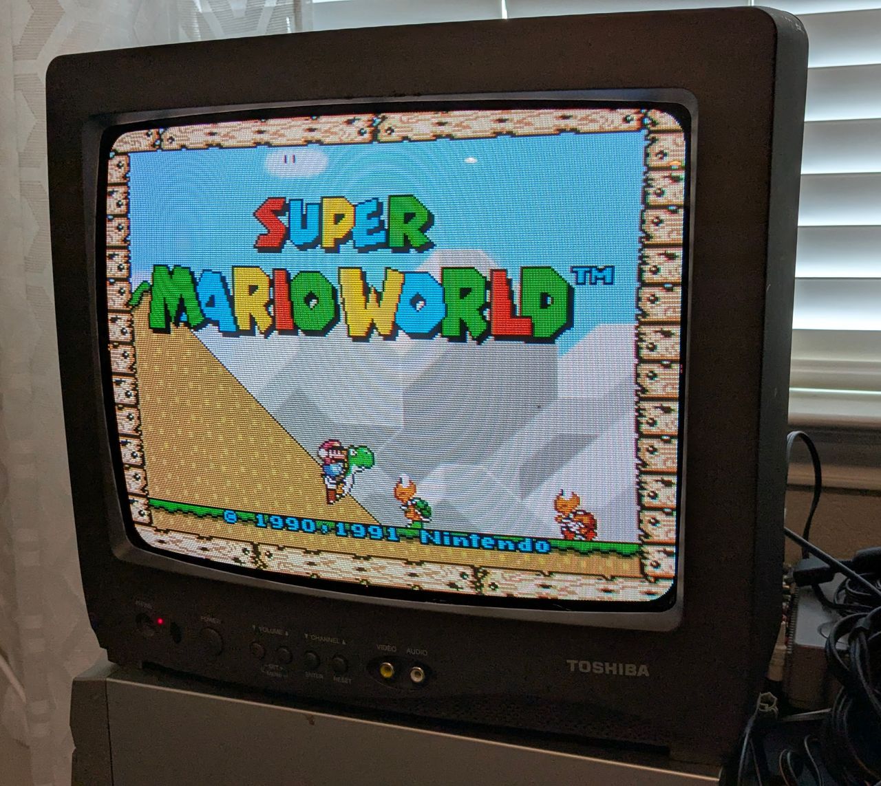
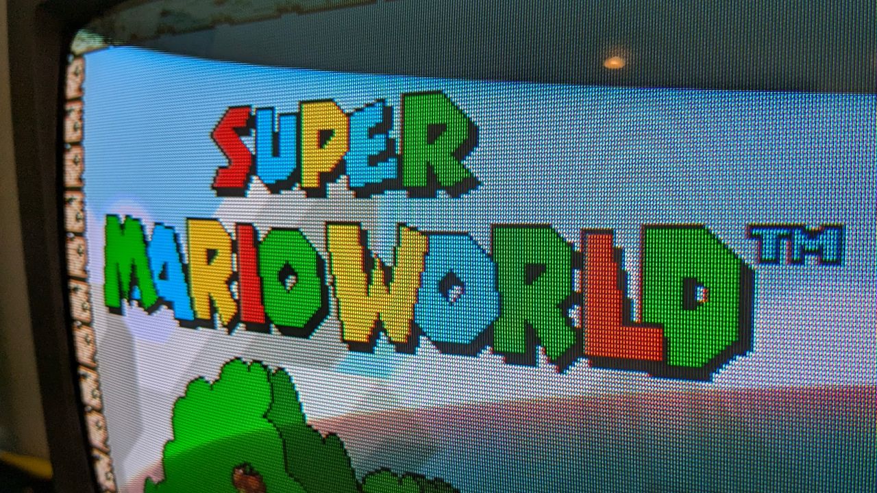
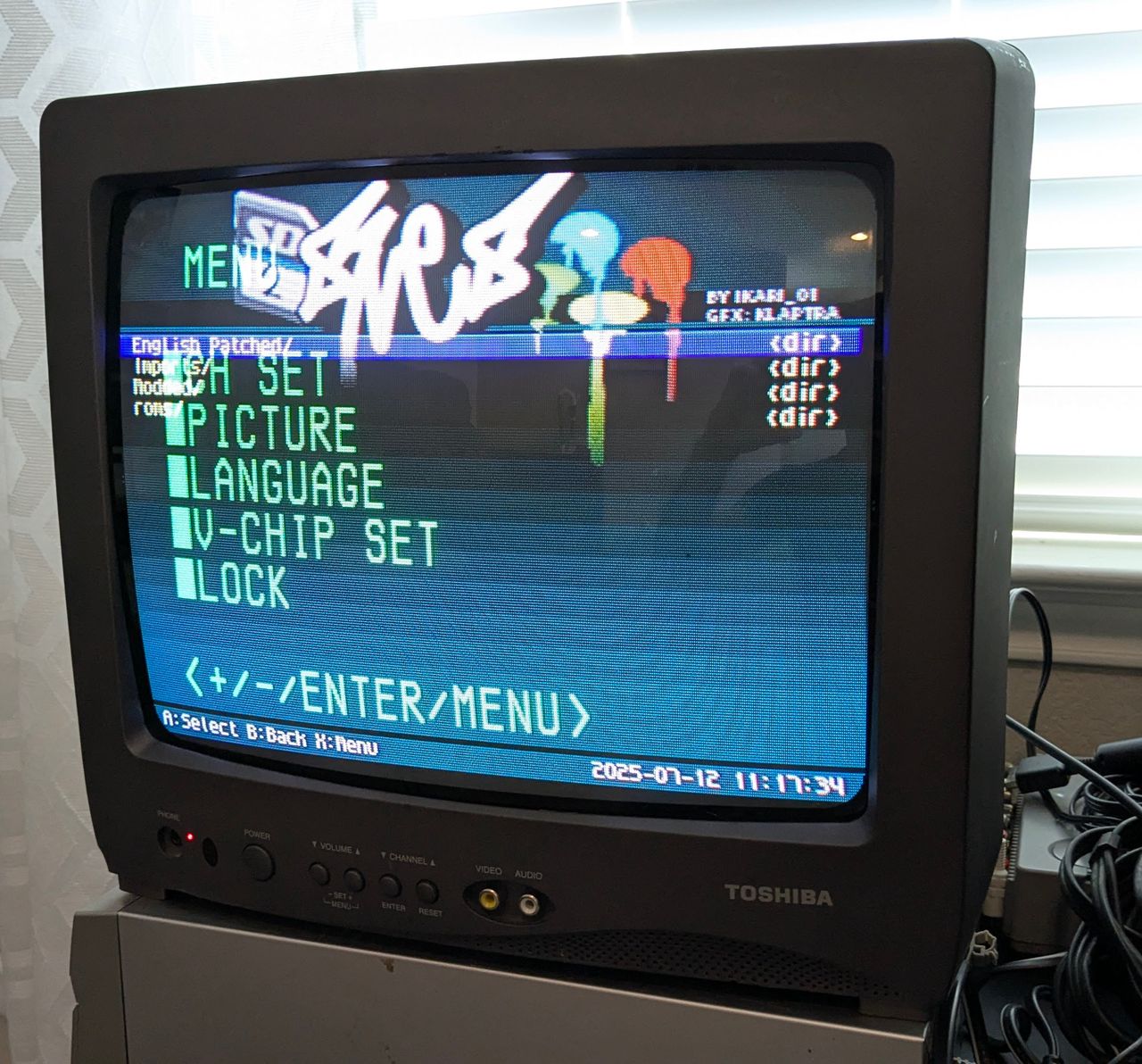
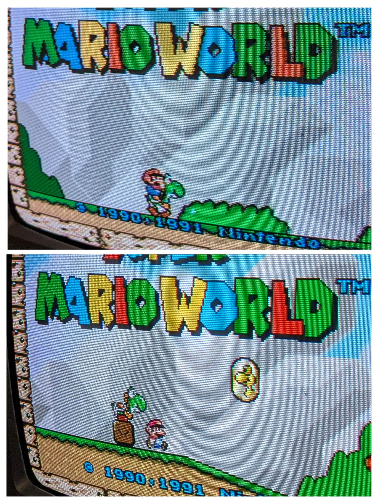
Games
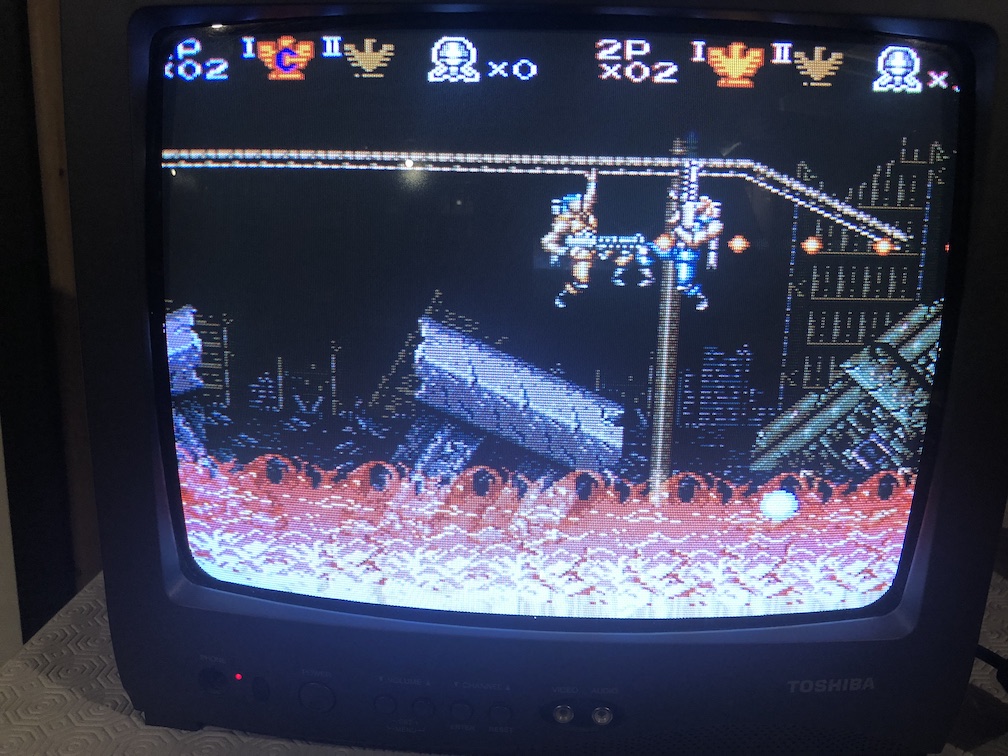
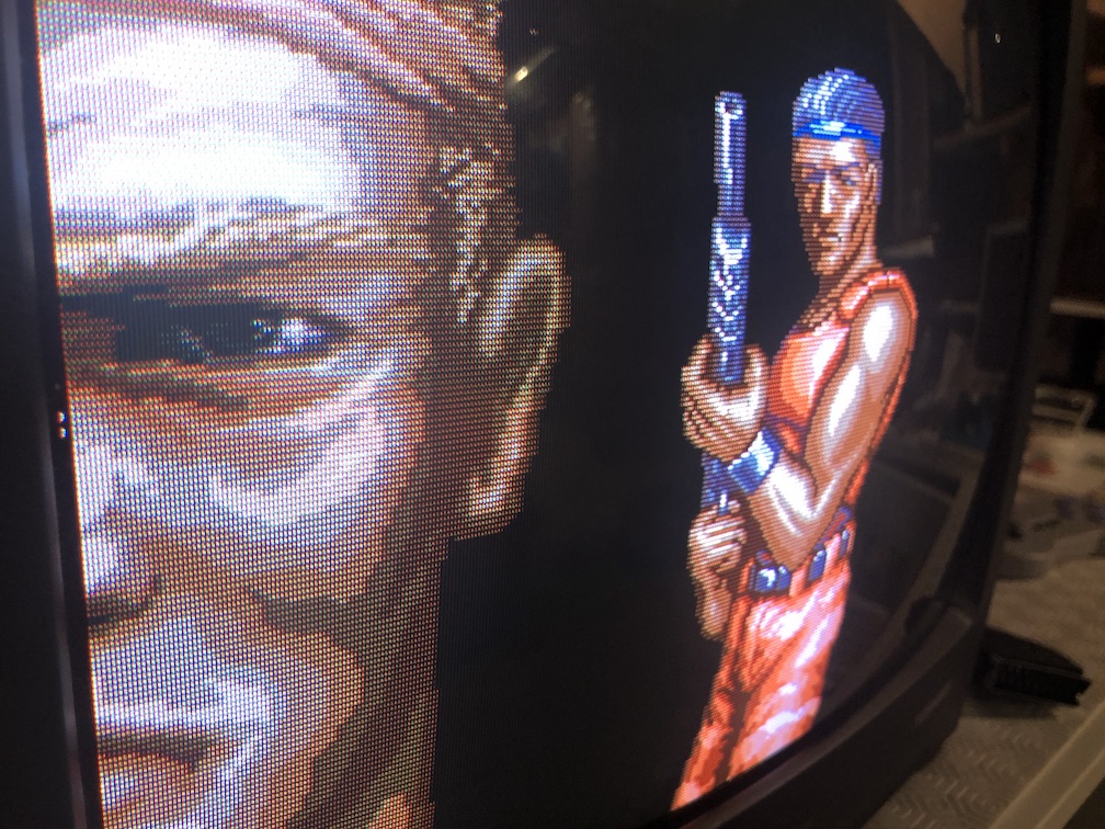
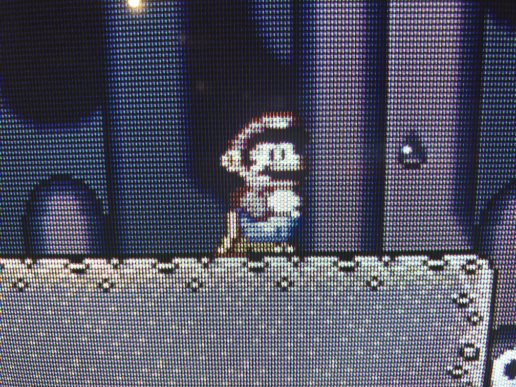
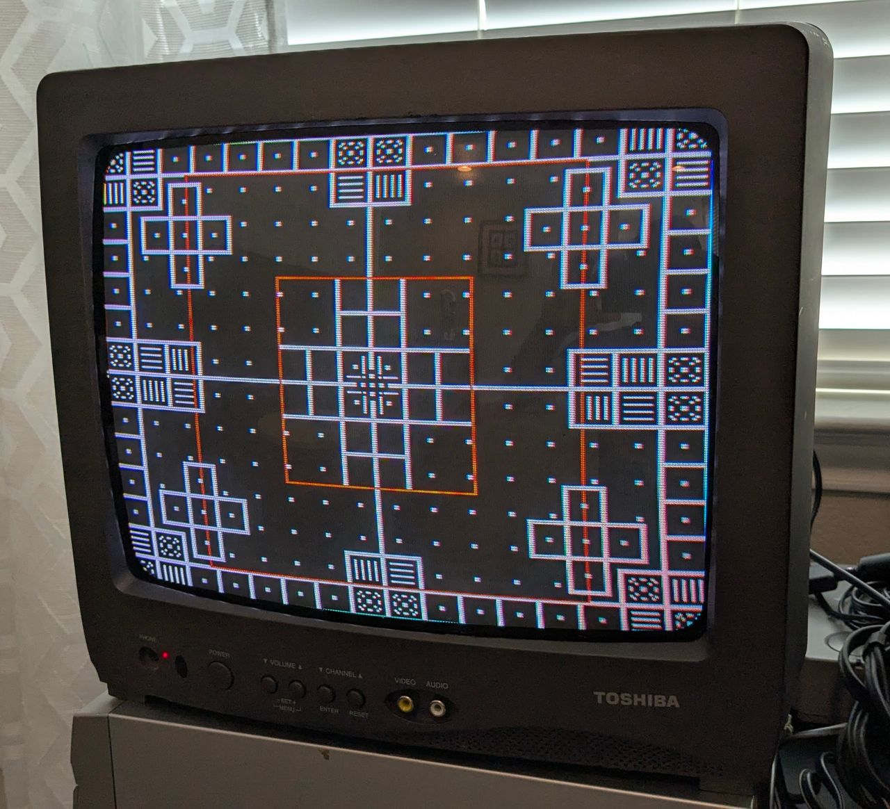
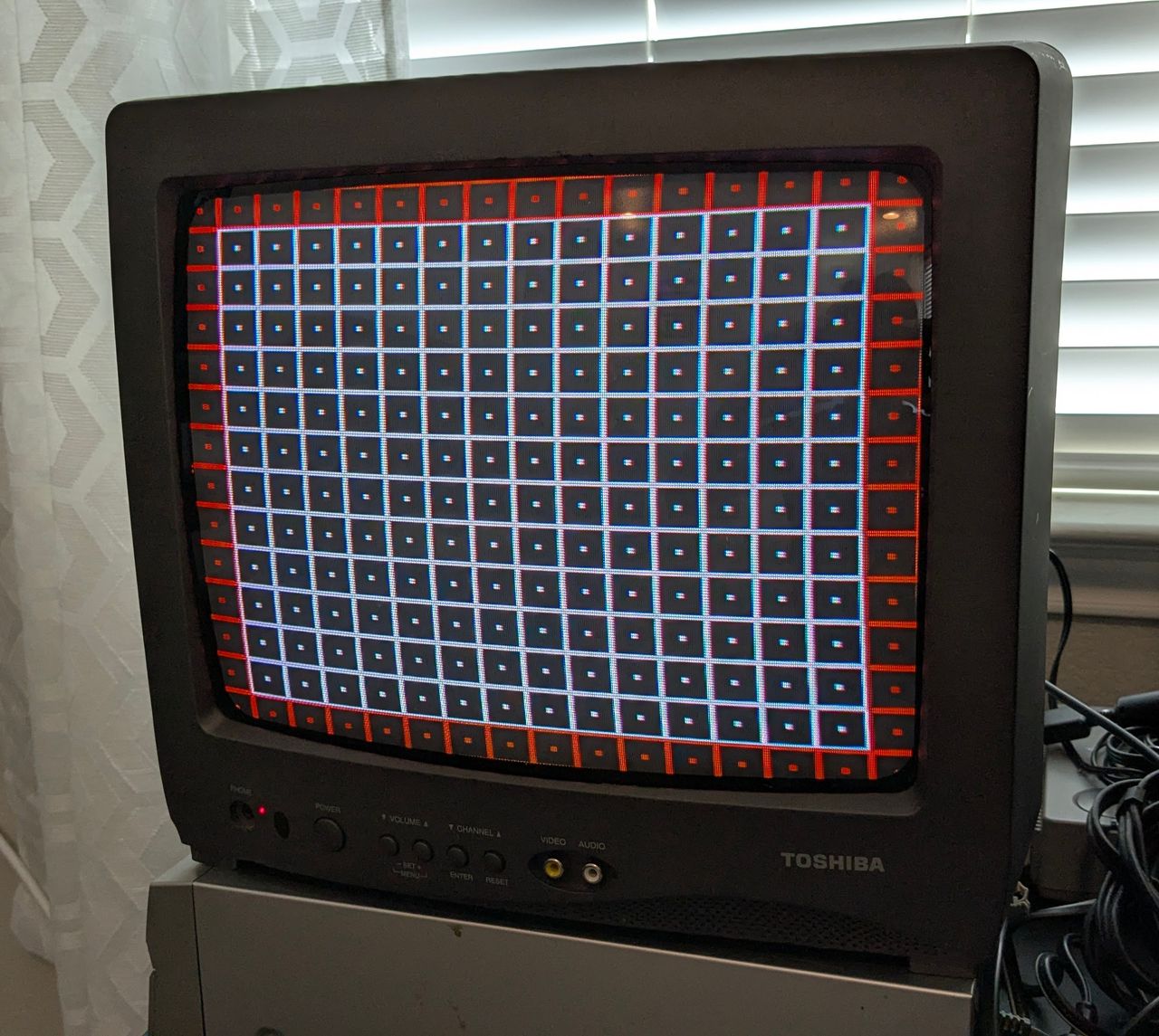
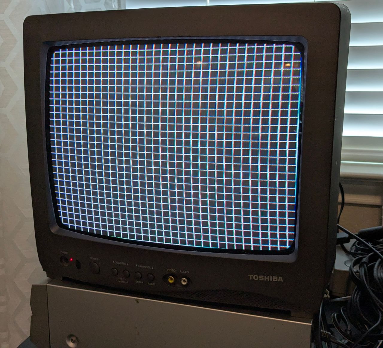
Pictures
Mod Photos
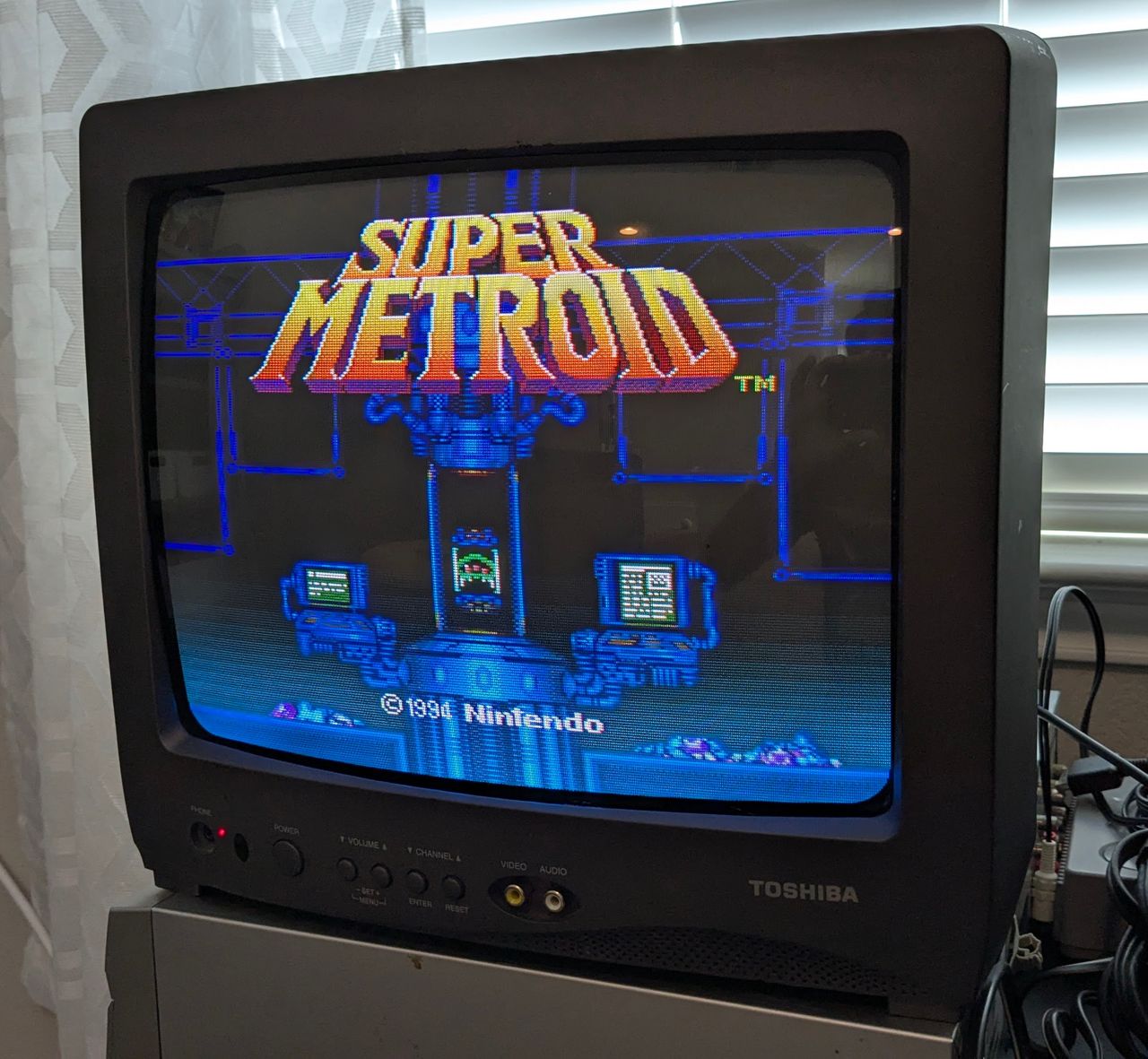
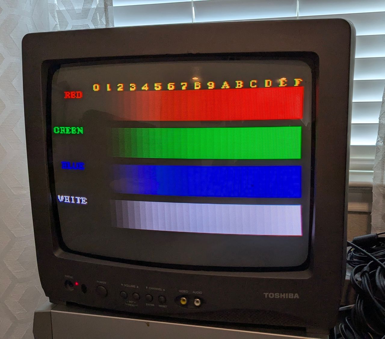
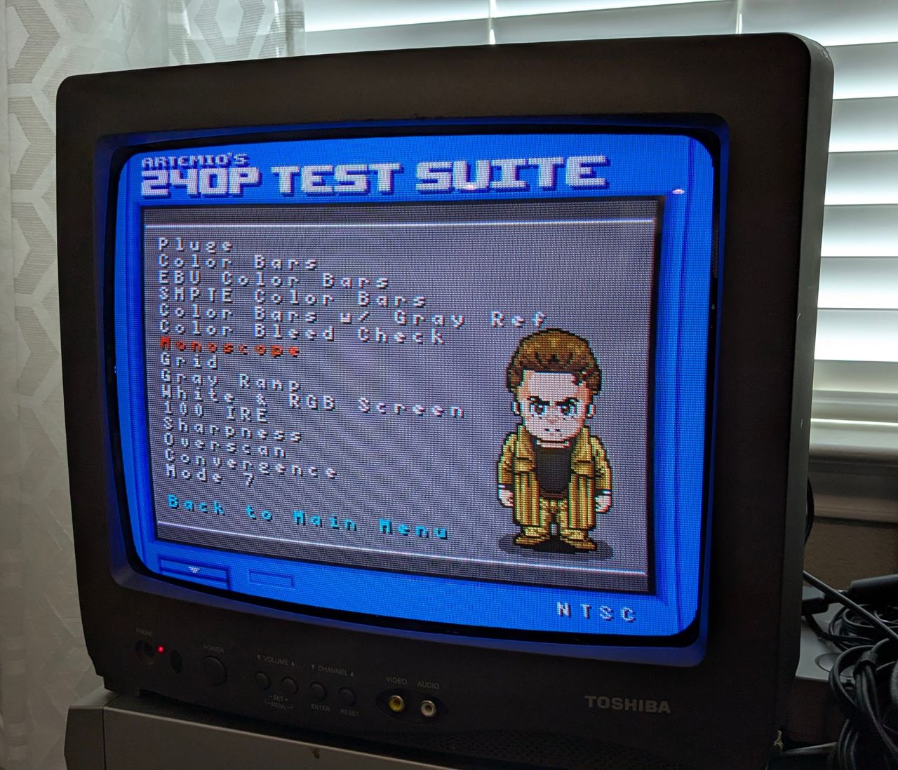
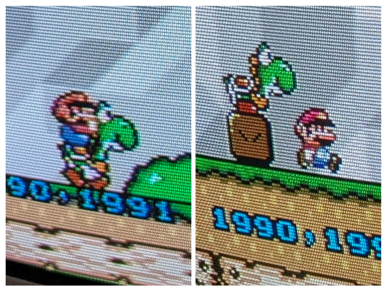
Reference Photos