JVC AV-20020
JVC AV-20020 CRT RGB mod
I couldn’t find the service manual or a mod tutorial for this particular set, so I followed the JVC AV-27220 mod Ian Ramsey did. JVC AV-20020 uses the same chassis as the JVC AV-27220, and the RGB mod was more or less the same, except I used different resistor values.
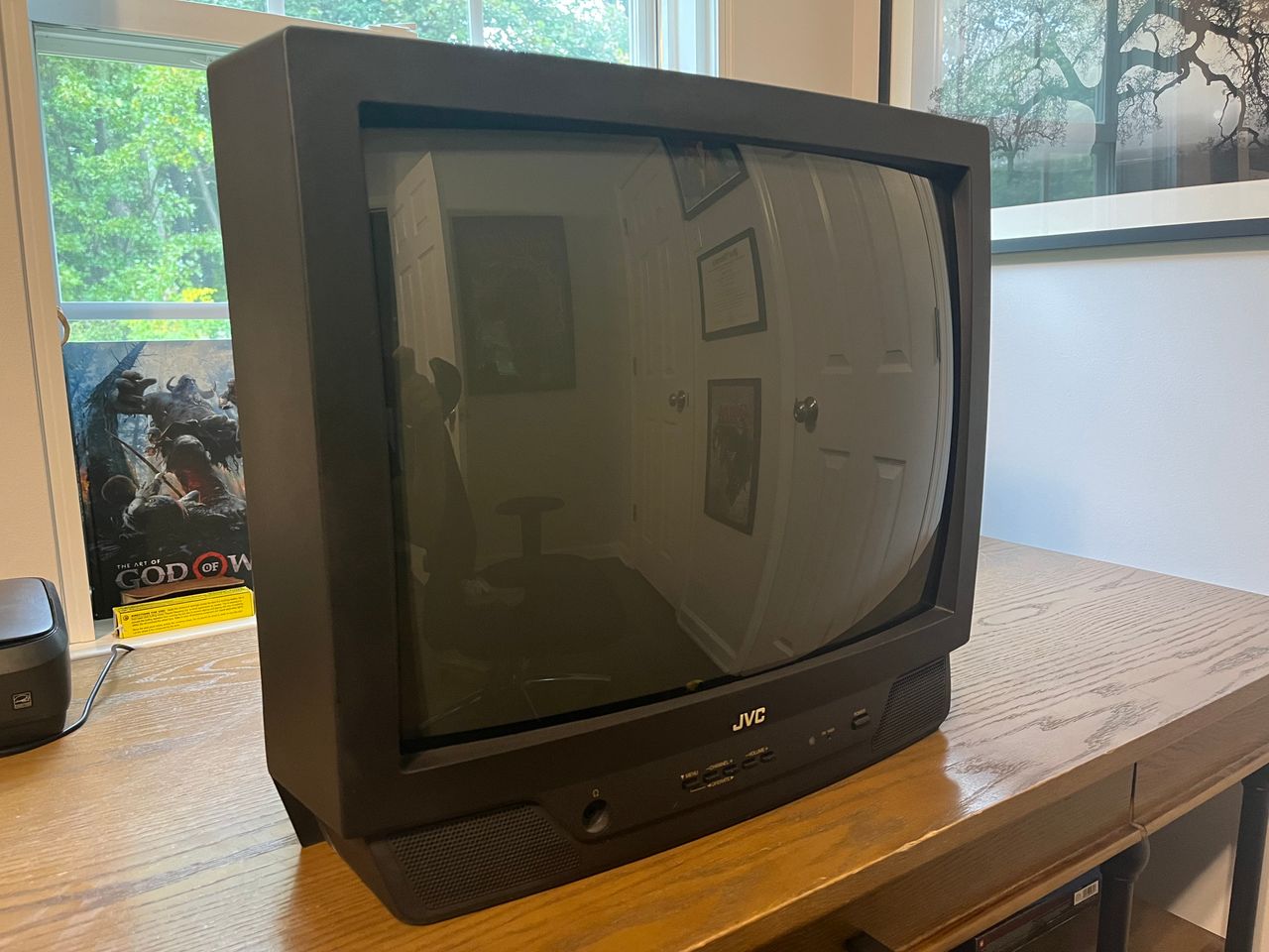
The JVC AV-20020 is a 20", basic curved consumer CRT television released around 1999.
It is RGB moddable.
View full CRT details and more mod examples →
This mod should also work for the below models
- JVC AV-20010
- JVC AV-20020
- JVC AV-20120
- JVC AV-20121
- JVC AV-20220
- JVC AV-20221
- JVC C-20210
Contributors
Thank you to everyone who contributed to this guide:
- John Figueroa — author, RGB mod and pictures
CRT safety
Caution
You can die doing this! So read carefully! CRT TV is not a toy. Do not open a CRT TV. If you don't have any prior knowledge about handling high voltage devices, this guide is not for you. CRT TV contains high enough voltage (20,000+ V) and current to be deadly, even when it is turned off.
Plan of attack
Manuals and Datasheets
Specs
- Year: 2001
- Format: NTSC
- Chassis: FV4
- Tube: Samsung A51KRE89X
- Jungle Chip: Toshiba TA1242N
- OSD Chip: Mitsubishi M37272MA
- Screen Size: 20"
- Inputs: Composite, RF
RGB mux diagram
Disassembly
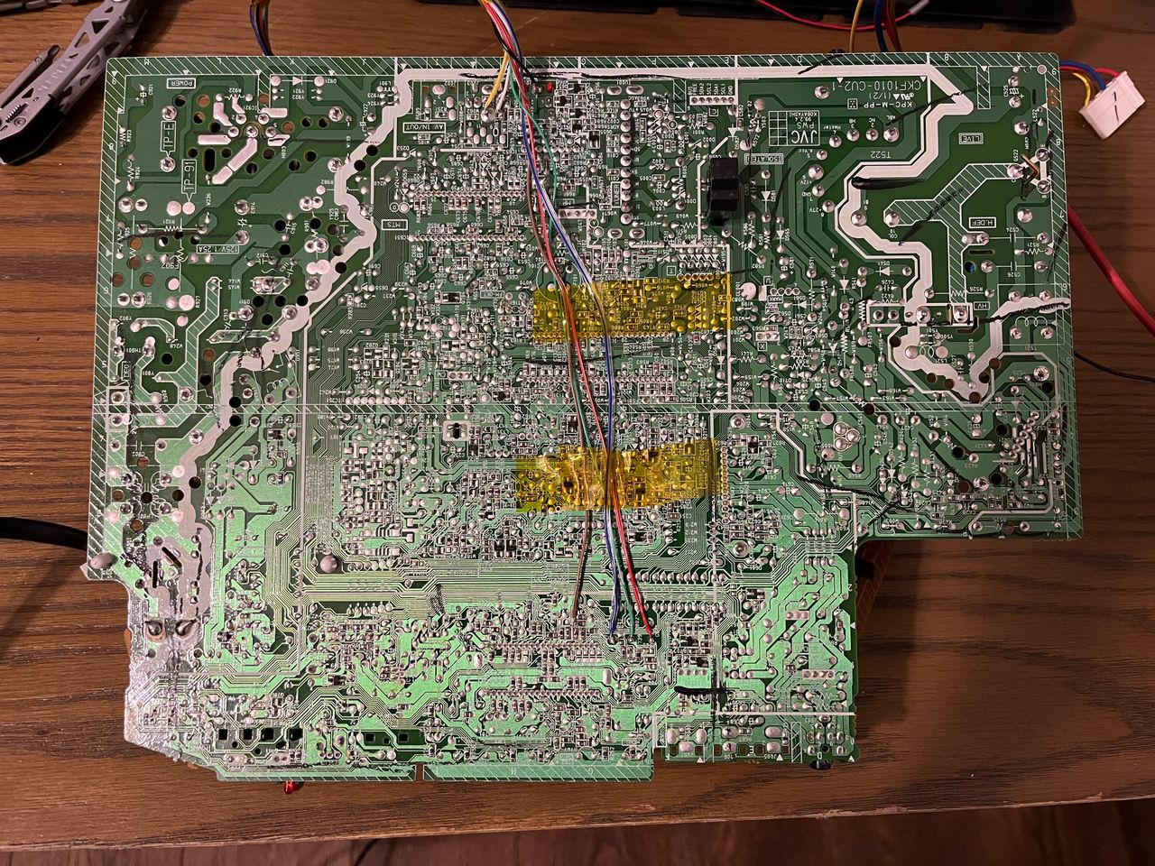
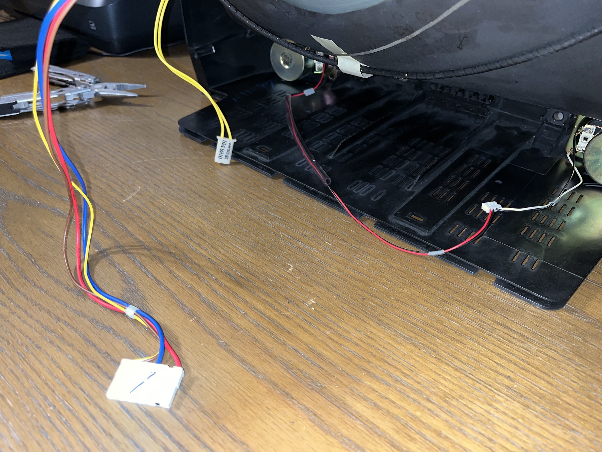
After pulling the back of the case off and discharging the tube, I removed the anode cap. After that there were only three wire bundles to disconnect in order to get the chassis. From left to right in the picture below are the yoke/deflection wires, degauss coil wire that goes around the tube and stereo speaker wires. Also, most importantly, don’t forget to remove the ground wire that goes to the neck board.
Performing the mod
This modification, similar to many JVC models, is quite straightforward. I used Sunthar’s RGB tuner to adjust the resistor values for this set and determined that 1.2 kΩ resistors are suitable for the RGB lines (1 kΩ should also work well according to the calculations), along with 220 Ω resistors to ground.
STEP 1: Remove the following components
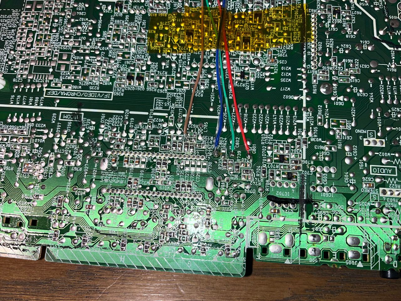
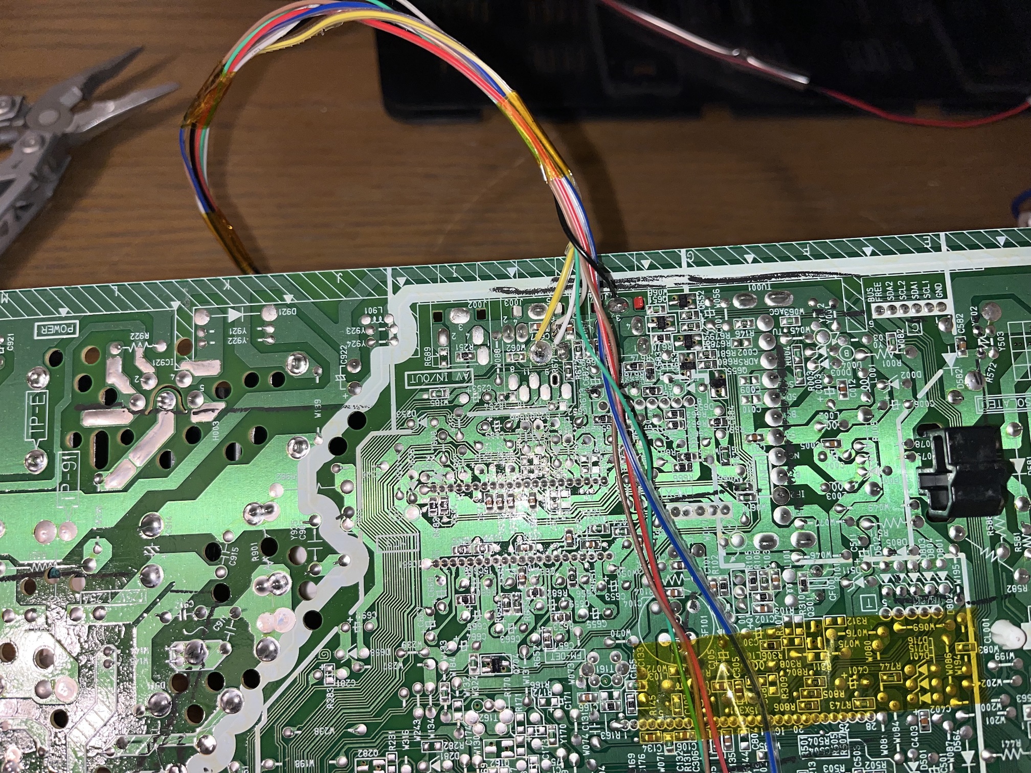
I removed resistors R738, R740, and R742. There are the RGB resistors to the ground. Measure twice and mark before you remove.
- R738 (1 kΩ)
- R740 (1 kΩ)
- R742 (1 kΩ)
STEP 2: Solder RGB, blanking wires
The brown wire is our blanking line and was soldered to R735. You won’t see my resistors in line with the connections made because I used Sunthars MUX Board to carry the resistors and to supply the 5V need for the blanking circuit; it’s cleaner and much easier to work on your CRT using Sunthar’s tools.
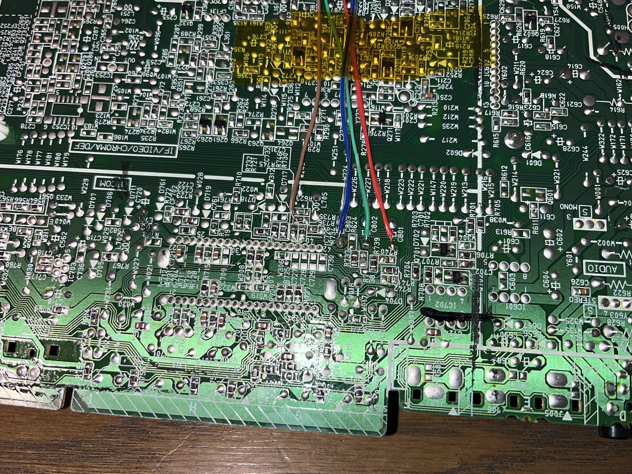
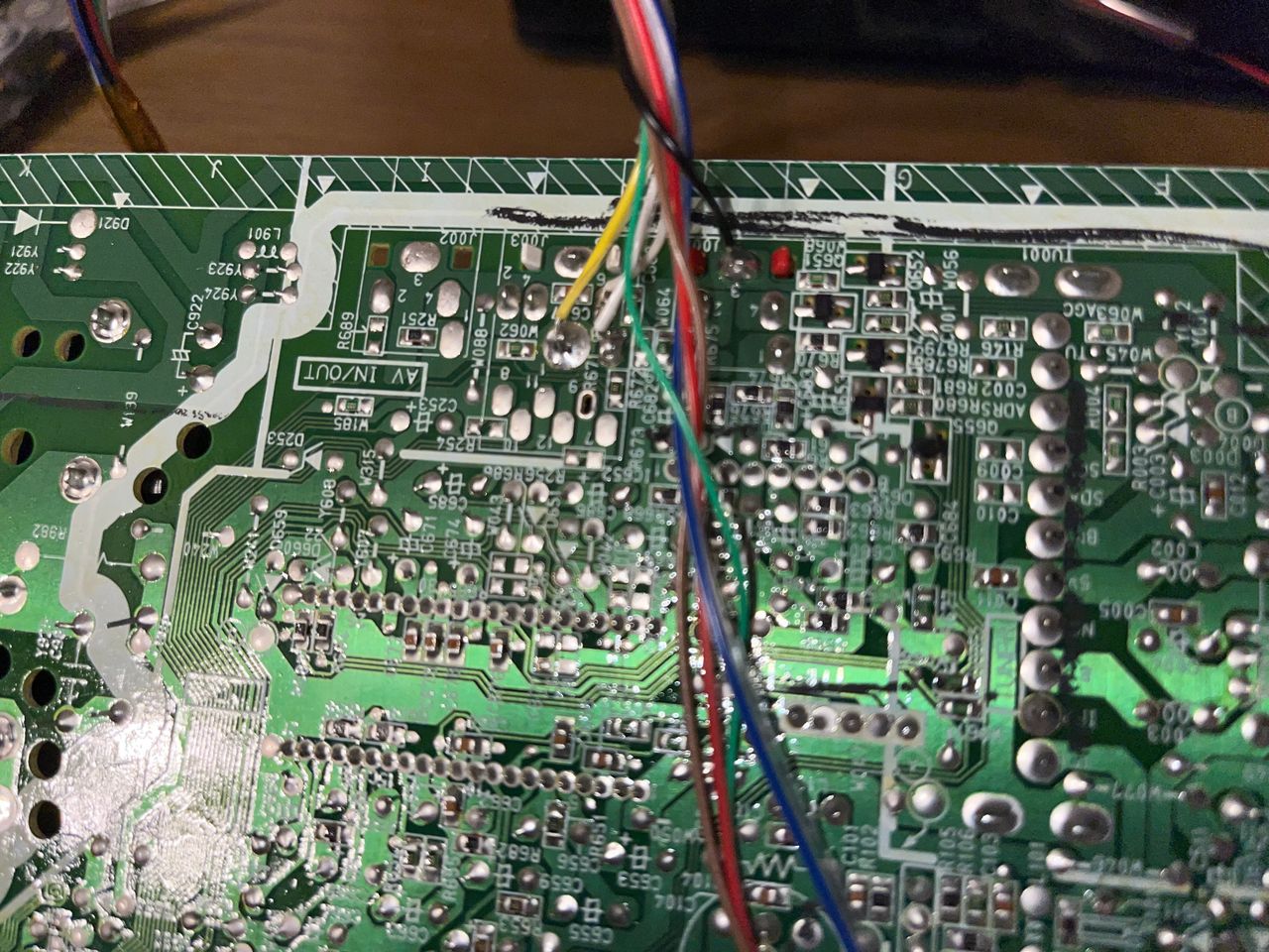
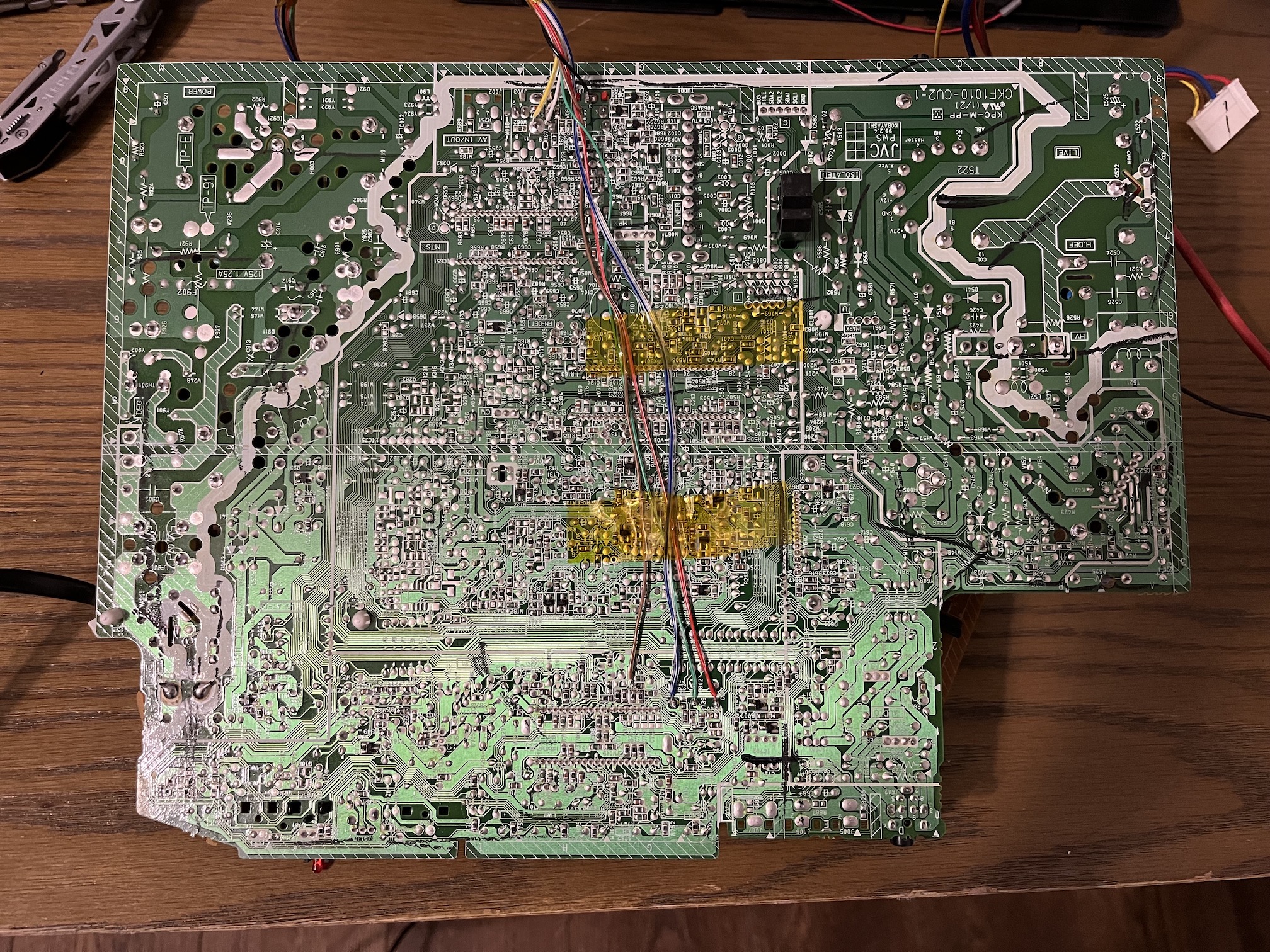
STEP 3: Solder audio, ground and sync
Next, you’ll wire in composite sync, left/right audio, and ground at the below location on the board. This looks a lot more complex than it actually is and it doesn’t really help to point you to resistor/capacitor numbers in this case; all you really need to do here is make sure your board is oriented the same way as in this picture below, with the composite barrel jacks facing up, and remember that with the Sunthar MUX board kit the white wire is Left Audio, and the gray wire is Right Audio, the yellow wire is Composite Sync, and the black wire is Ground.
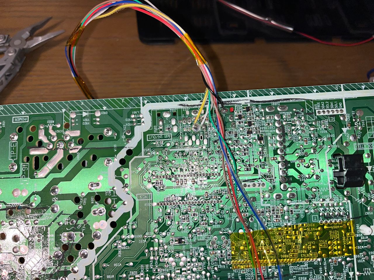
This is how my board looked after all wires were soldered into place; I used Kapton tape for strain relief on the wires, but you may want to use hot glue or some other solution:
Once all the wires were soldered in and secured with tape or glue, you can move on to the fun part: buidling your MUX board. As mentioned earlier, for this model CRT I used 1.2 kΩ for RGB inlines, and 220 Ω for ground termination. We always use 1 kΩ resistors for left and right audio. The following picture shows the MUX board fully built out per the above specifications, with R9 on the Sunthar MUX board shorted in order to supply the 5 volt signal needed to switch on the Blanking Circuit as well as a diode on R11 to prevent current from returning to our input device (game console). Refer to Sunthar’s documentation for diode placement, as it’s the one component soldered to the MUX board that requires a specific orientation.
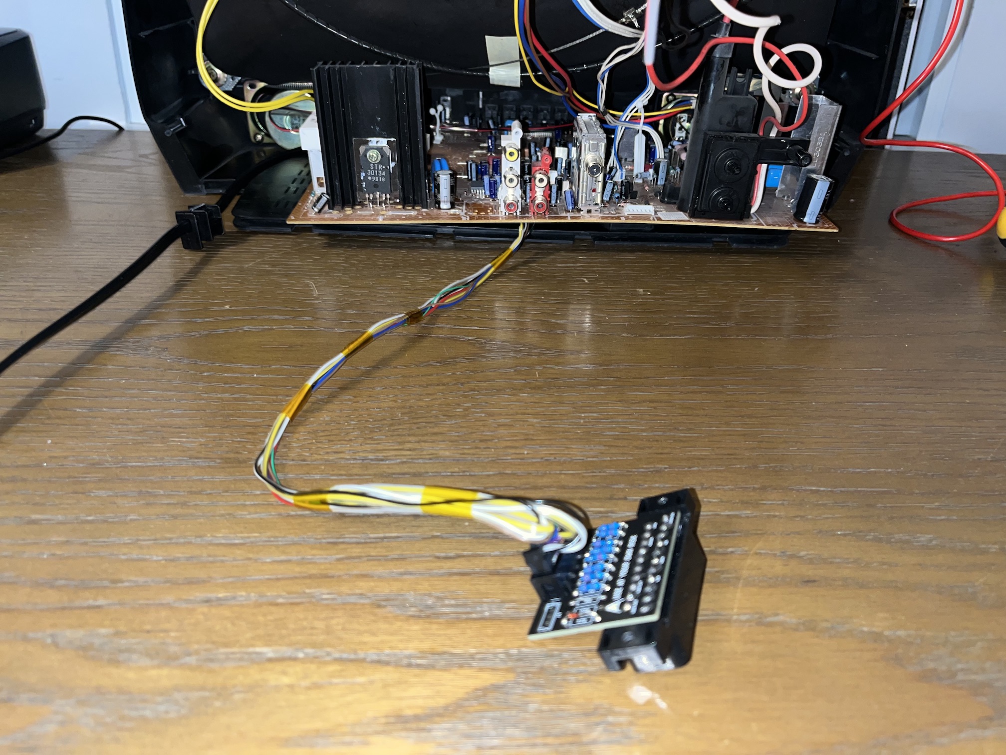
STEP 4: Build your mux board
This mod uses the RGB mux board. This is optional, but will make your mod easier and stable. You can also create the circuit presented in the schematics above without the board. Please also checkout the mux calculator to play with your own values.
| Component | Value |
|---|---|
| RGB/OSD inline resistor (chassis) | 4.7kΩ |
| Removed RGB/OSD resistor (chassis) | 1.5kΩ |
| RGB inline diode method (chassis) | Yes |
| 0.1μF caps replaced (chassis) | Yes |
| RGB termination (R1, R2, R3) | 220Ω |
| RGB inline (R4, R5, R6) | 1.2kΩ |
| Audio LR (R7, R8) | 1kΩ |
| Diode (R9) | 1N4148 |
| Blanking Ground Resistor (R10) | open |
| Blanking Resistor (R11) | 1kΩ |
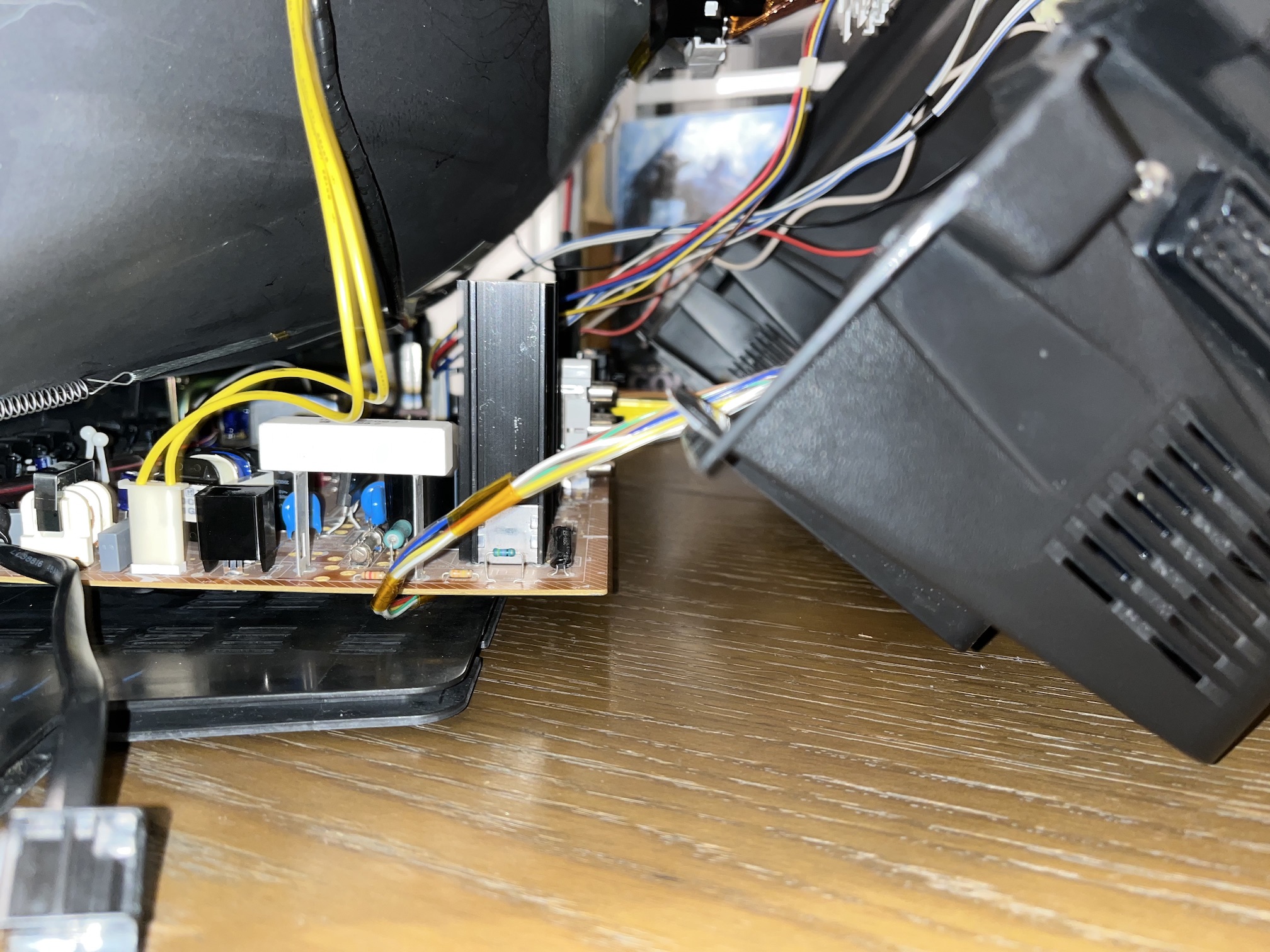
STEP 5: Attach the female SCART connector to TV
In the picture below, you can see how I chose to bundle and route the wiring and where I chose to cut out space for the SCART head; refer to this documentation for advice on getting great SCART cut-out results.
Pictures
Reference Photos