RGB mux board
Overview
The objective of this board is to simplify the RGB mux mod performed on the CRT. It has few benefits.
- No need to spend time connecting all the grounds together
- Easier to solder the RGB in-line resistors, diodes and 75ohm resistors (this can get quiet messy)
- Ability to disconnect the back of the CRT TV when needed (10 pin IDC connector)
- Adds stability to the mod. No need for hot glue etc. to hold things in place
- Tested with various CRTs (Note: not all CRTs are RGB moddable. Tested CRTs are listed on this site)
Currently, two versions of these boards are being shipped.
Warning
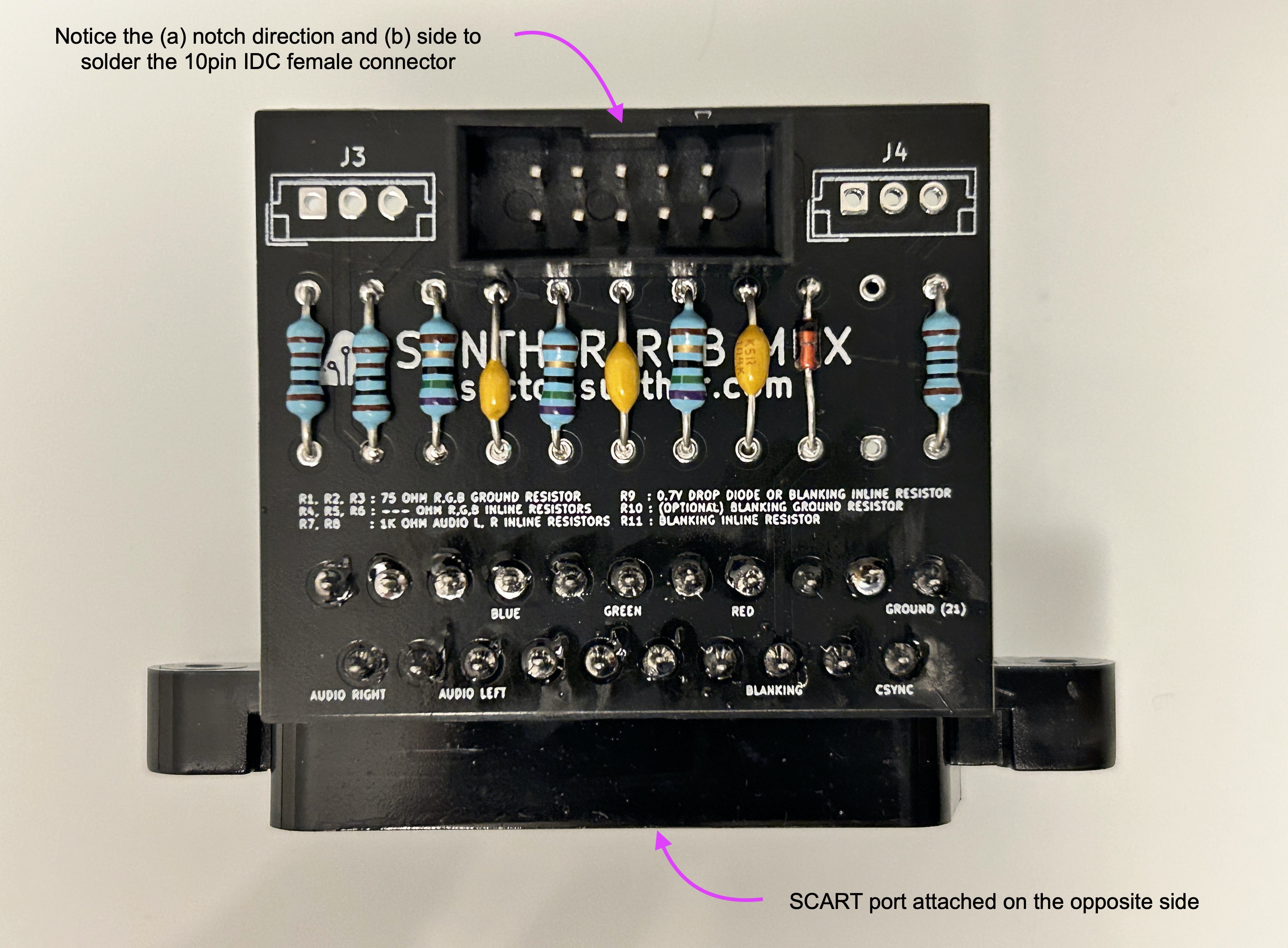
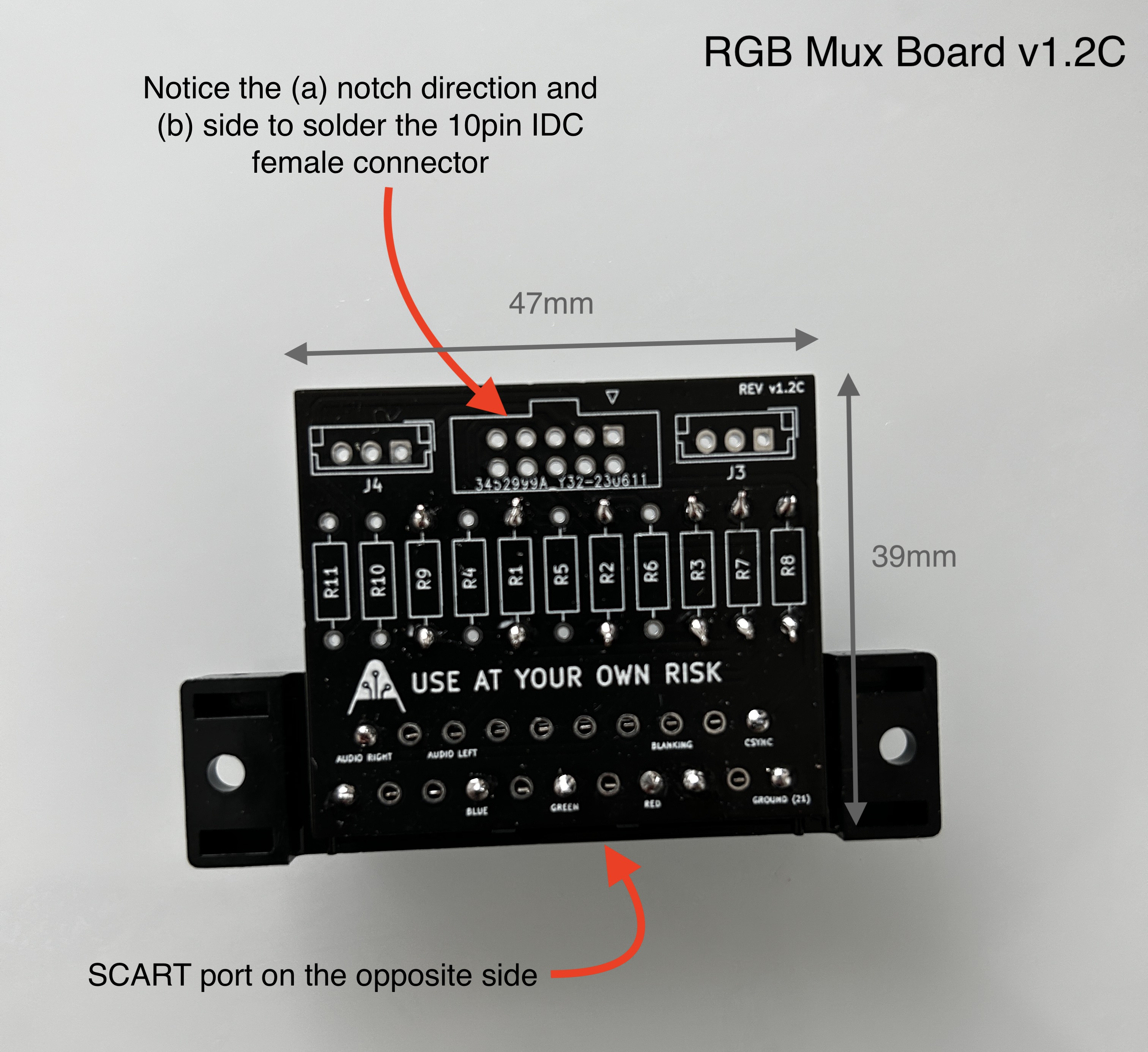
It's important to be aware that the connectors may not be soldered in place, requiring you to solder them yourself on the appropriate side and in the correct orientation.
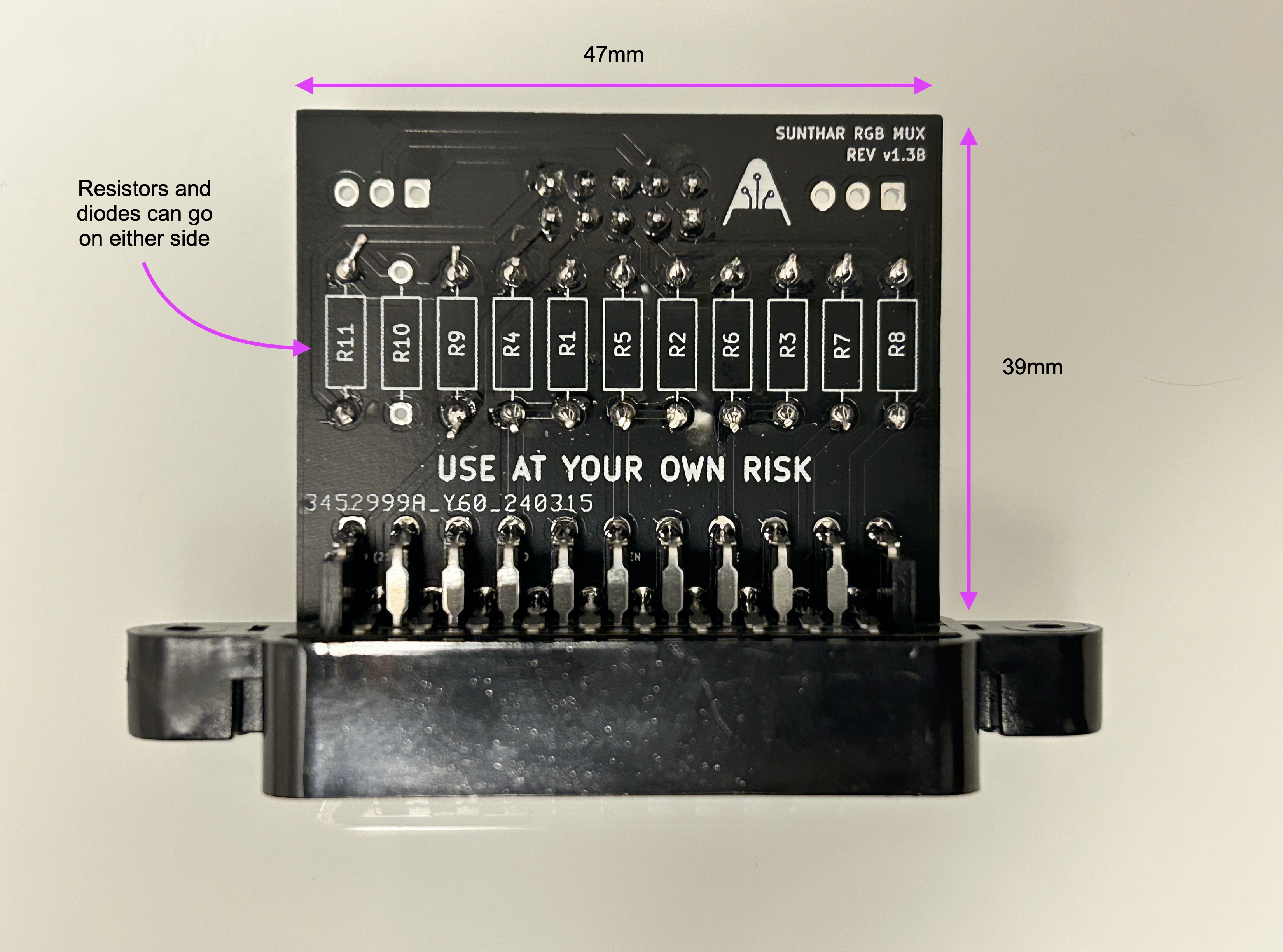
Sunthar RGB Mux v1.3B
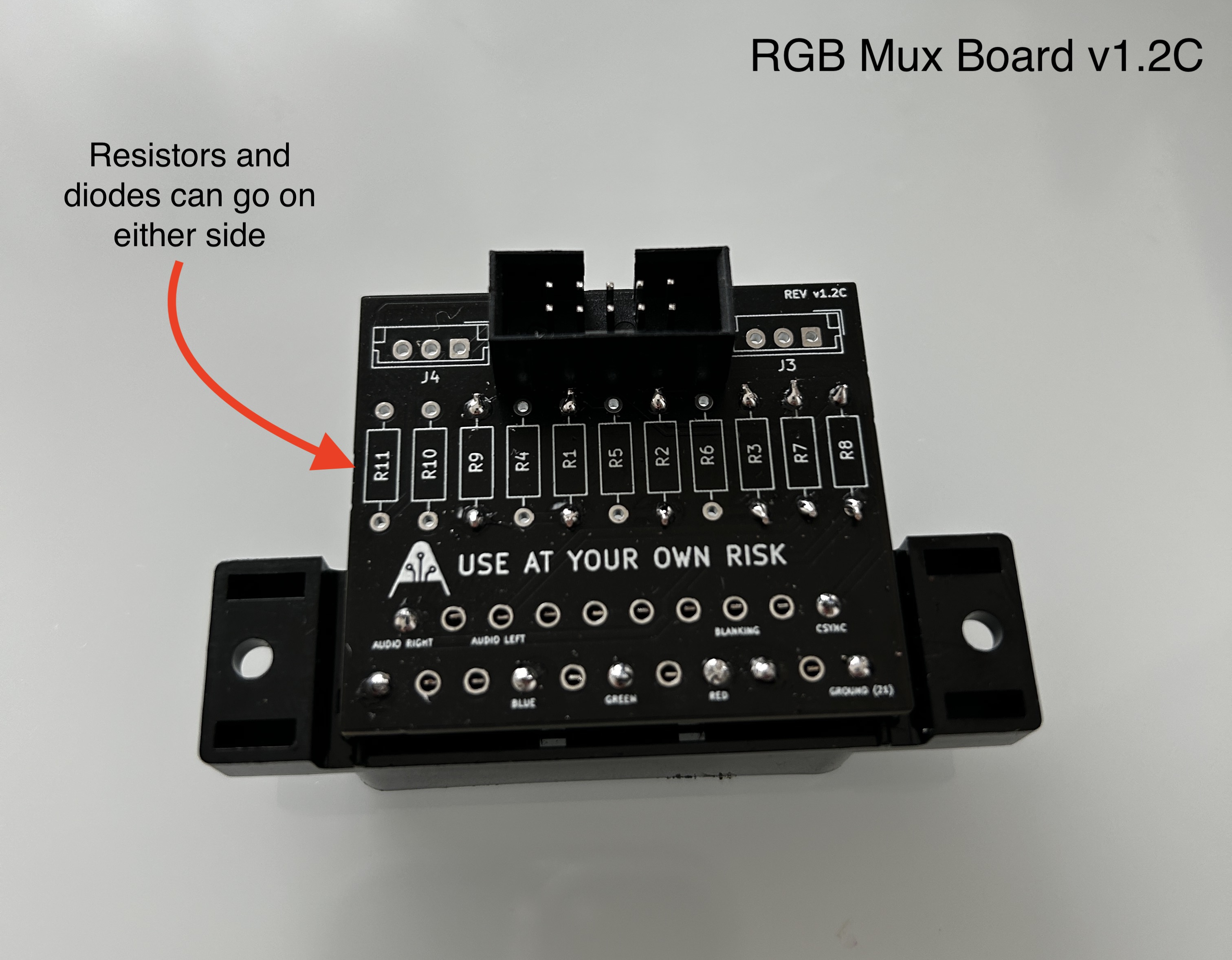
Sunthar RGB Mux v1.2C
Schematics
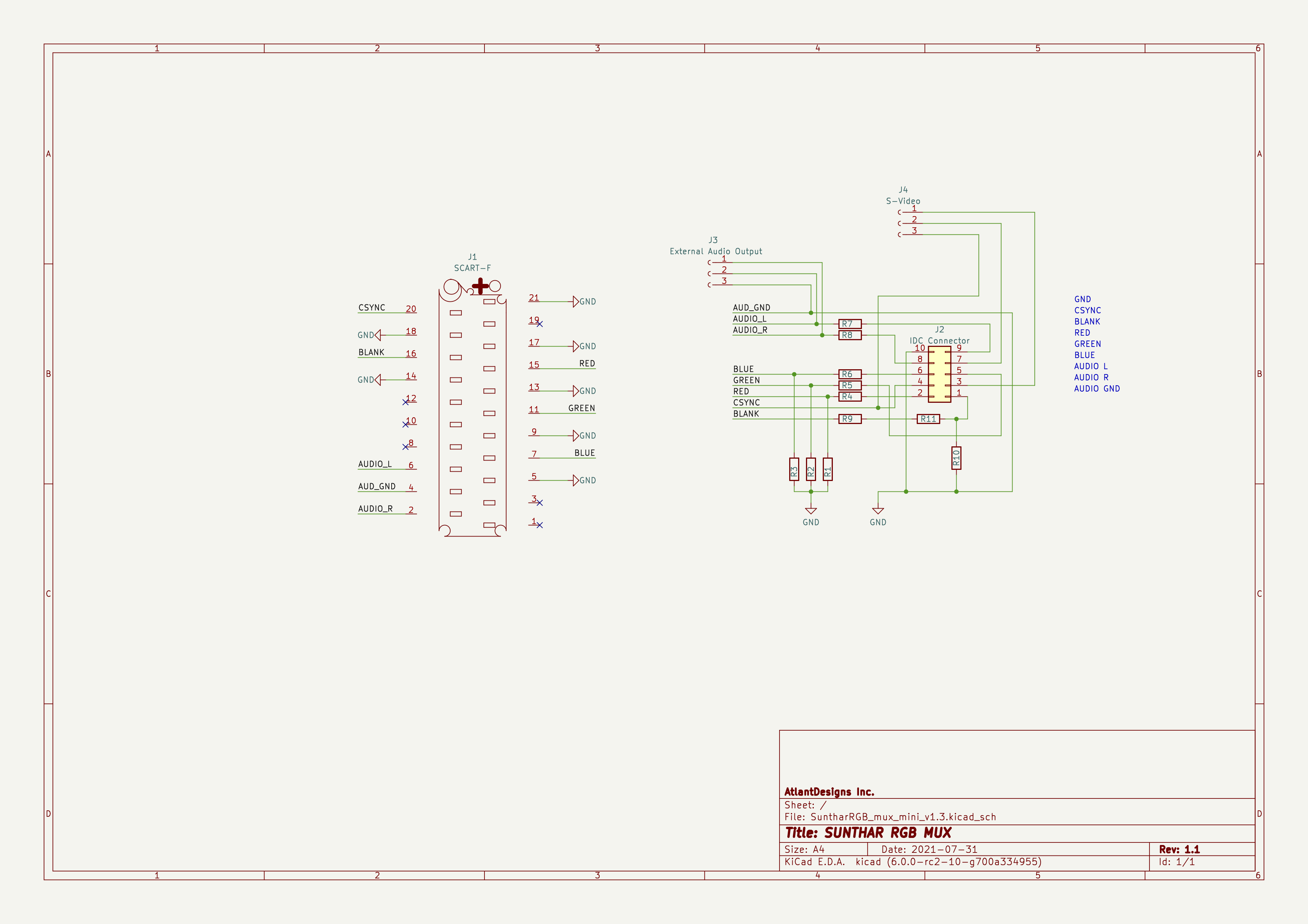
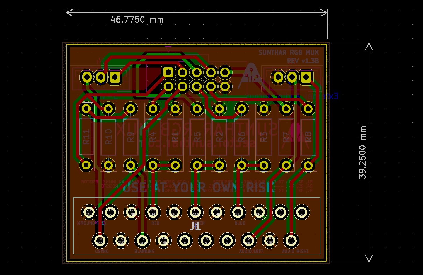
RGB mux board
This is a two layer board. The best way to explain this board is through pictures. Below is an image of the latest board revision.
This board is now availabe for you to order directly as well. You can download the gerber file and manufacture your own boards.
Design summary
v1.3B mini mux board
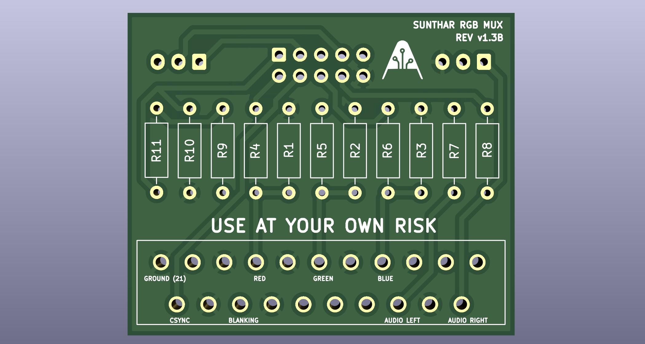
Below are the resistors and descriptions for them
| Resistors | Value | Notes |
|---|---|---|
| R1, R2, R3 | 75Ω | R, G, B terminating resistors |
| R4, R5, R6 | ? | R, G, B inline resistors (value for this needs to be calculated) |
| R7, R8 | 1kΩ | Resistors for audio left and audio right ( mono and stereo ) |
| R9 | 1N1418 | Diode to prevent current from the CRT going back to the device |
| R10 | ? | Optional blanking voltage divider resistor |
| R11 | ? | Short this if you need 4V to 5V, or use it for voltage dividing |
R10 and R11 forms a voltage divider. This is optional and only to be used in cases where < 5V is needed.
Typical setup would look like the below
Example: 5V blanking signal with just diode
- R9 has a 1N1418 diode with stripe facing away from the SCART connector
- R10 is left open
- R11 had a resistor or is shorted
How to use the voltage divider on the board
Tips
This method only makes sense if you don't already have any grounding resistors on your CRT main board's blanking line. Check your CRT schematics and layout of blanking to be sure.
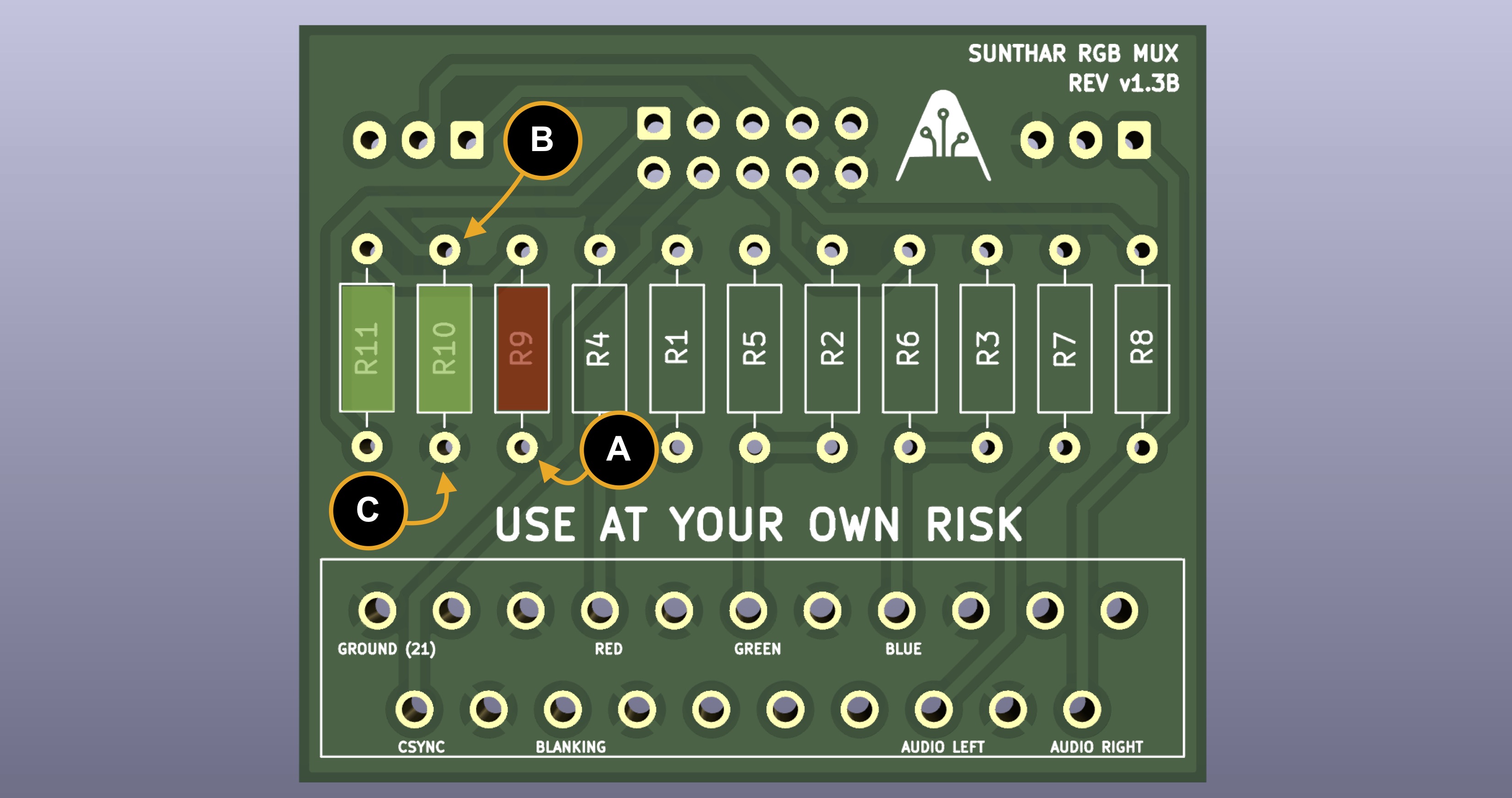
A5VBDivided voltageCGround
At point A you will have 5V from console. You can measure this by testing between A and C.
Example: 3V blanking signal
If you want 3V blanking signal, you can generate using the below method.
- R9 = 0.7V diode
- R11 = 1kΩ (let's keep this at 1kΩ for simplicity)
- R10 = 2.3 kΩ (calculated)
Calculate R10 using ohm law, voltage divider calculator
Vout in this case is blanking voltage. Vin in this case is 4.3V (5V - 0.7V)
- Vout = (Vin x R10) / (R10 + R11)
- R10 = (Vout x R11) / (Vin - Vout) = (3 X 1) / (4.3 - 3)
- R10 = 3/1.3 = 2.3 kΩ
Other values for R10 and R11 can also be used to achieve this. Example: R10 = 2.8kΩ, R11 = 1.2KΩ. You can use a voltage divider calculator to find those values.
Testing
Connect the SCART cable to your game console and the ribbon cable to the IDC made adapter. Turn on the console. Keep the CRT off.
You can test to see what voltages you are getting from the mux board (measure A and B). Make sure the mux board is not attached to your CRT when taking these measurements.
Also, to double confirm, measure voltage between the brown wire (blanking) and black wire from the ribbon cable to confirm if you are getting 3V.
IDC rainbow cable
The board was designed such that it took advantage of the IDC rainbow cable colors to be intuitive.
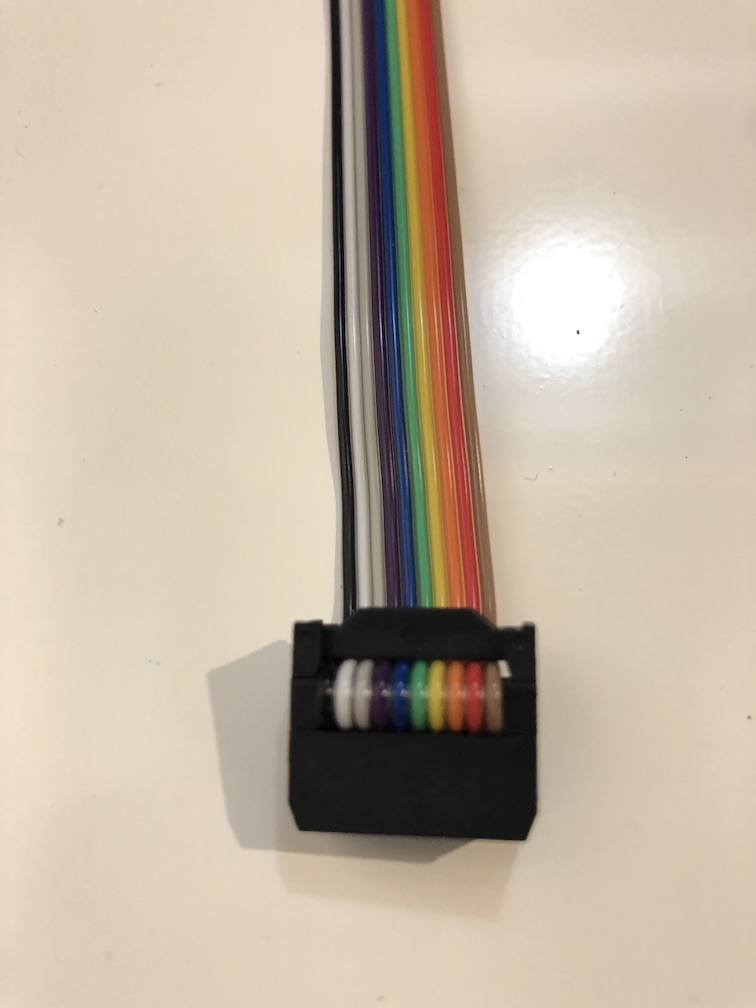
You can buy the necessary parts and ribbon cable separately and also crimp your own cable. All you need is a plyer that can apply an even force not to break the plastic tabs. Pay close attention to the orientation of the cable in relation to the notch. You want to make sure this is correct, otherwise you will be feeding 5V from console to the wrong pin.
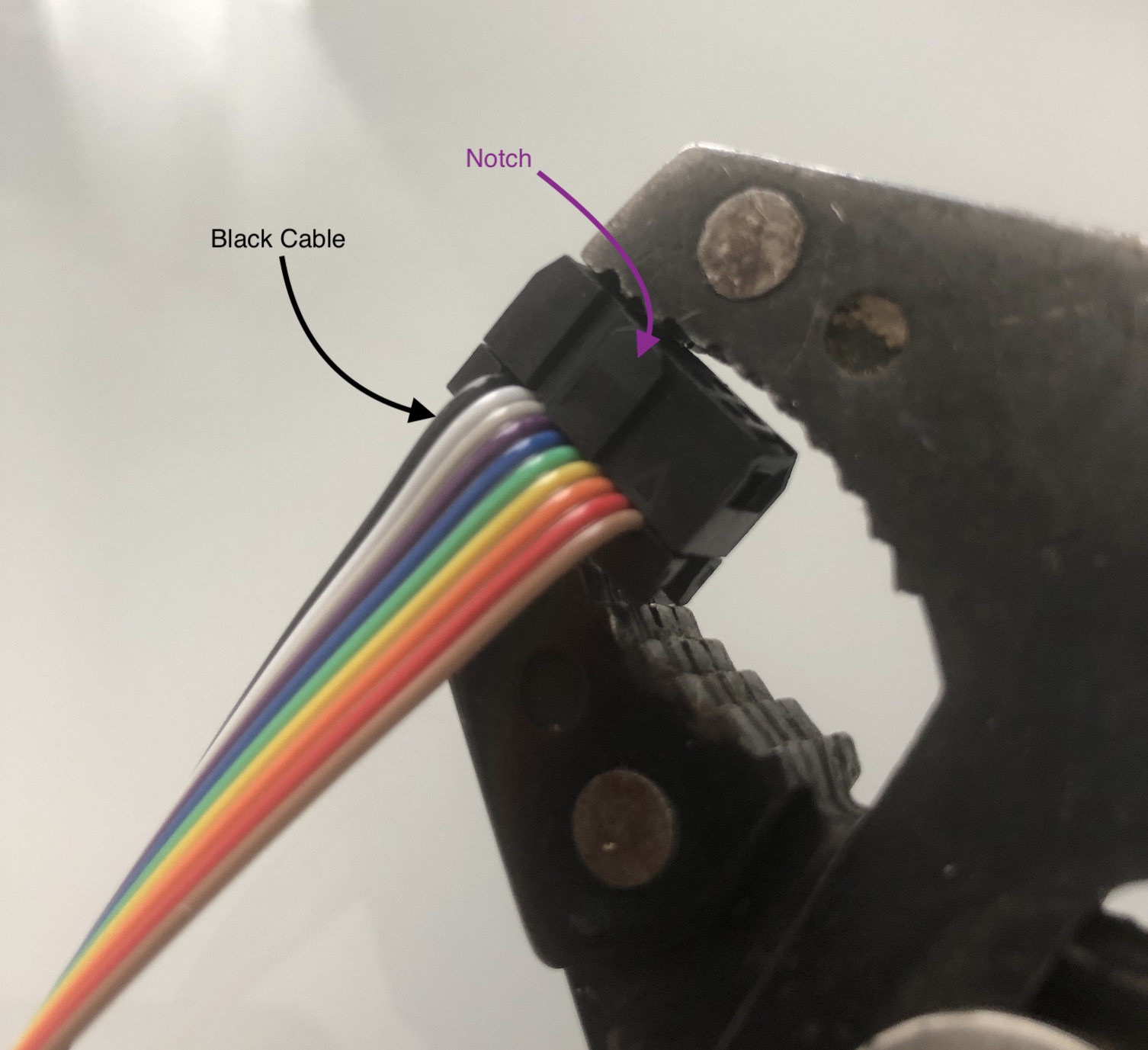
Warning
Make sure the cable is crimped exactly as shown on the above image. Black cable needs to be on the left side of the notch, when looking into the cable.
Below table provides an overview of the color of the cable and how it translates to RGB mod.
| Cable Color | Purpose |
|---|---|
| Brown | Blanking |
| Red | Red |
| Orange | Ground (opt) |
| Yellow | CSYNC |
| Green | Green |
| Blue | Blue |
| Purple | Audio Ground |
| Grey | Audio Right |
| White | Audio Left |
| Black | Common Ground |
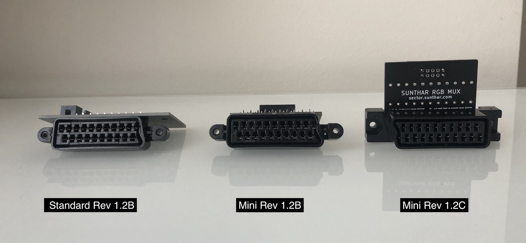
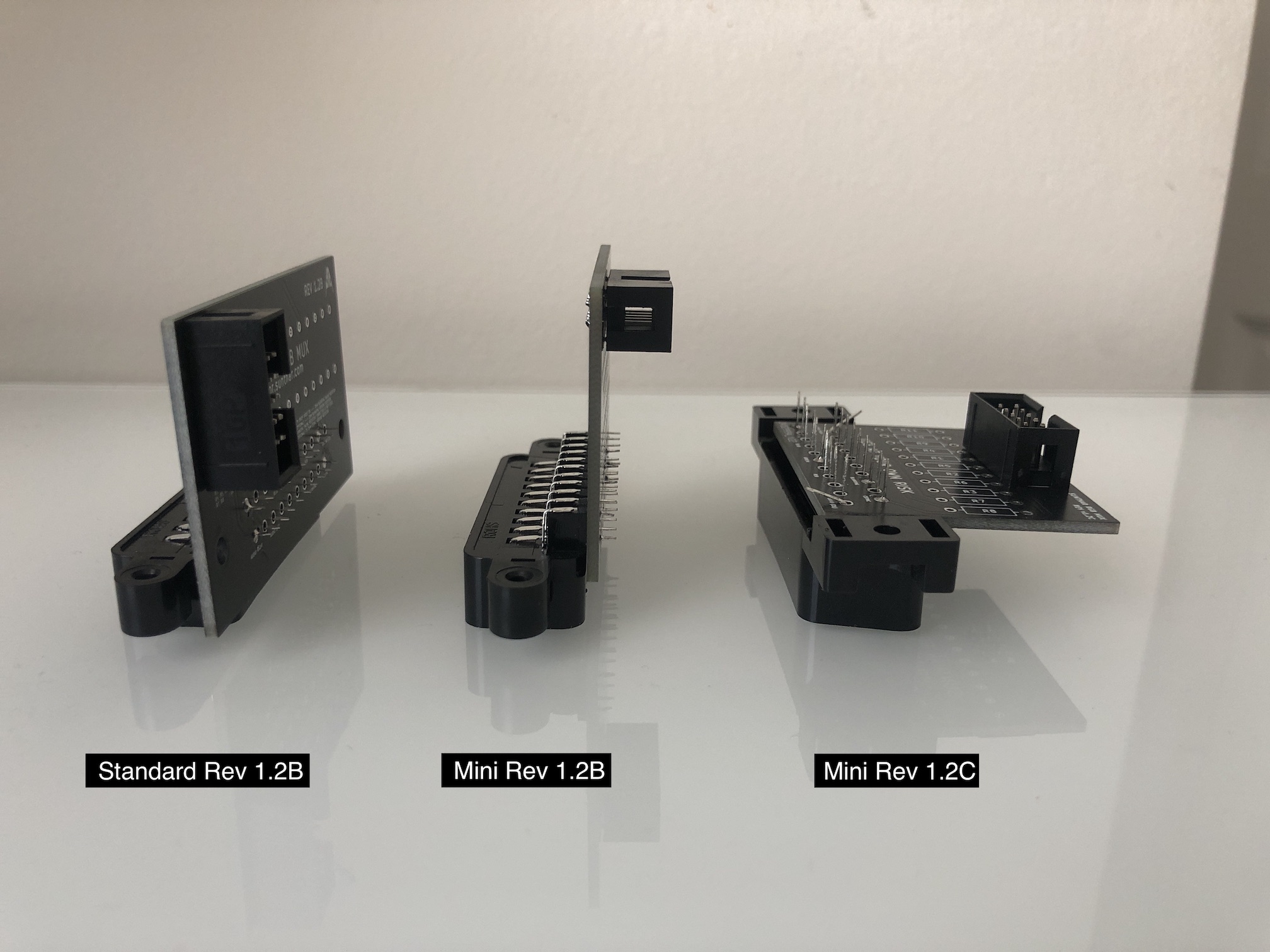
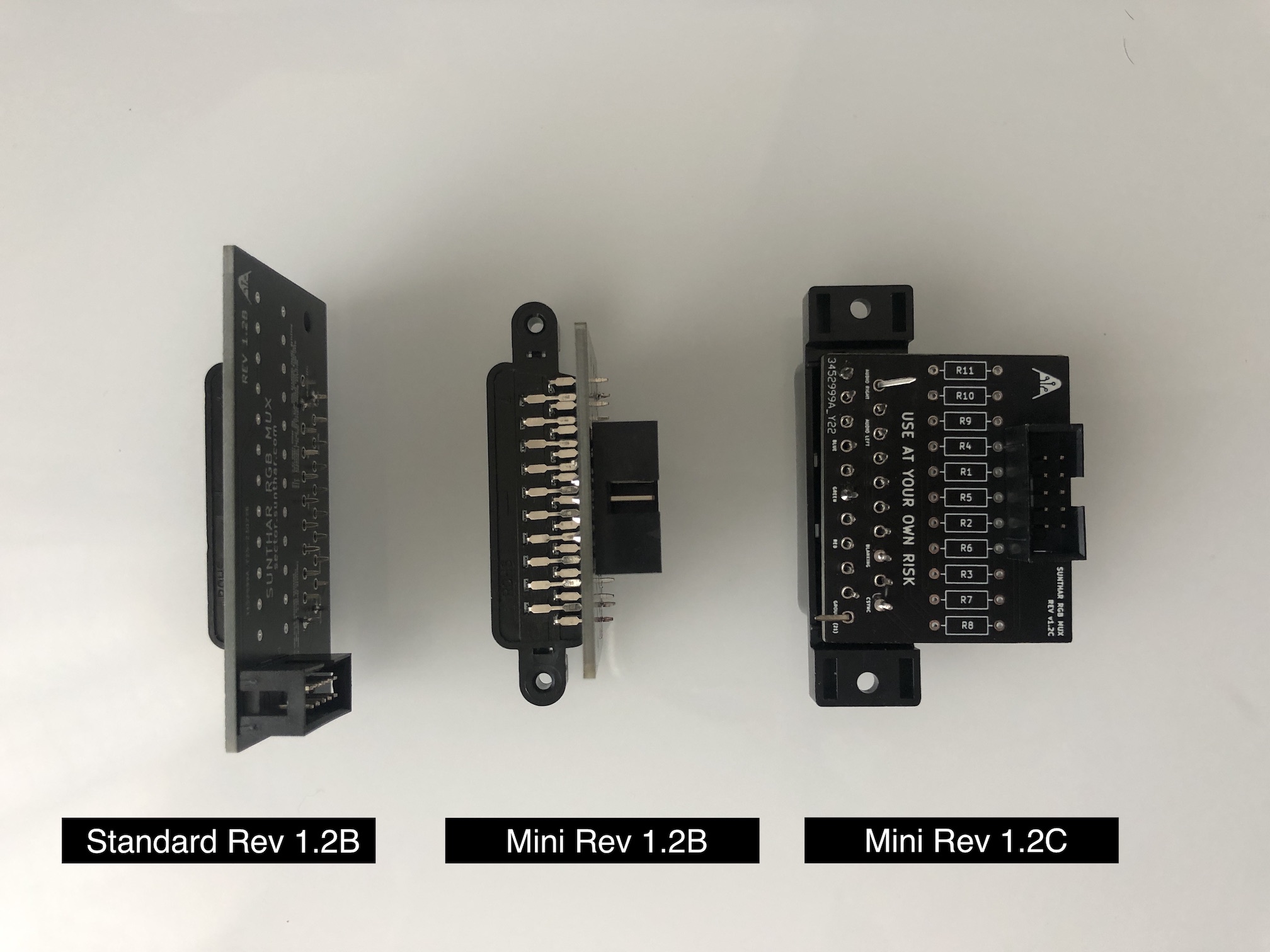
Various Boards
There are few differnt versions of the board made, such that you can easily fit it into any CRT TV.
- The standard 1.2B and mini 1.2B are practically the same, except the mini is much more narrower. It uses the 90 degree SCART connector and good for flush mount.
- The 1.2C was made for tighter spaces and utilizes the straight SCART connector that is a bit more sturdy and sticks out. This board is used on 27" JVC D-Series mod.