Sony (BG-1L) KV-LX34M31
Sony (BG-1L) KV-LX34M31 CRT RGB mod
The Sony KV-LX34M31 is a massive, highly sought-after 34" curved CRT television featuring a legendary Super Trinitron tube. Renowned in crt collection community for its superb geometry and vibrant color reproduction, this BG-1L chassis TV is famous for its built-in subwoofer and excellent picture quality.
View full CRT details and more mod examples →
Contributors
Thank you to everyone who contributed to this guide:
- Mark Robertson — contributor, RGB mod and pictures
CRT safety
Caution
You can die doing this! So read carefully! CRT TV is not a toy. Do not open a CRT TV. If you don't have any prior knowledge about handling high voltage devices, this guide is not for you. CRT TV contains high enough voltage (20,000+ V) and current to be deadly, even when it is turned off.
Plan of attack
Manuals and Datasheets
Specs
- Format: PAL, PAL60, SECAM, NTSC3.58, NTSC4.43
- Chassis: BG-1L
- Tube: Super Trinitron Tube A80JYV51X
- Jungle Chip: Sony CXA2050S
- OSD Chip: Sony CXP85332A-238S
Schematics
RGB mux diagram
Prepare the mux diagram. If you are building your own circuit, this diagram should help.
Performing the mod
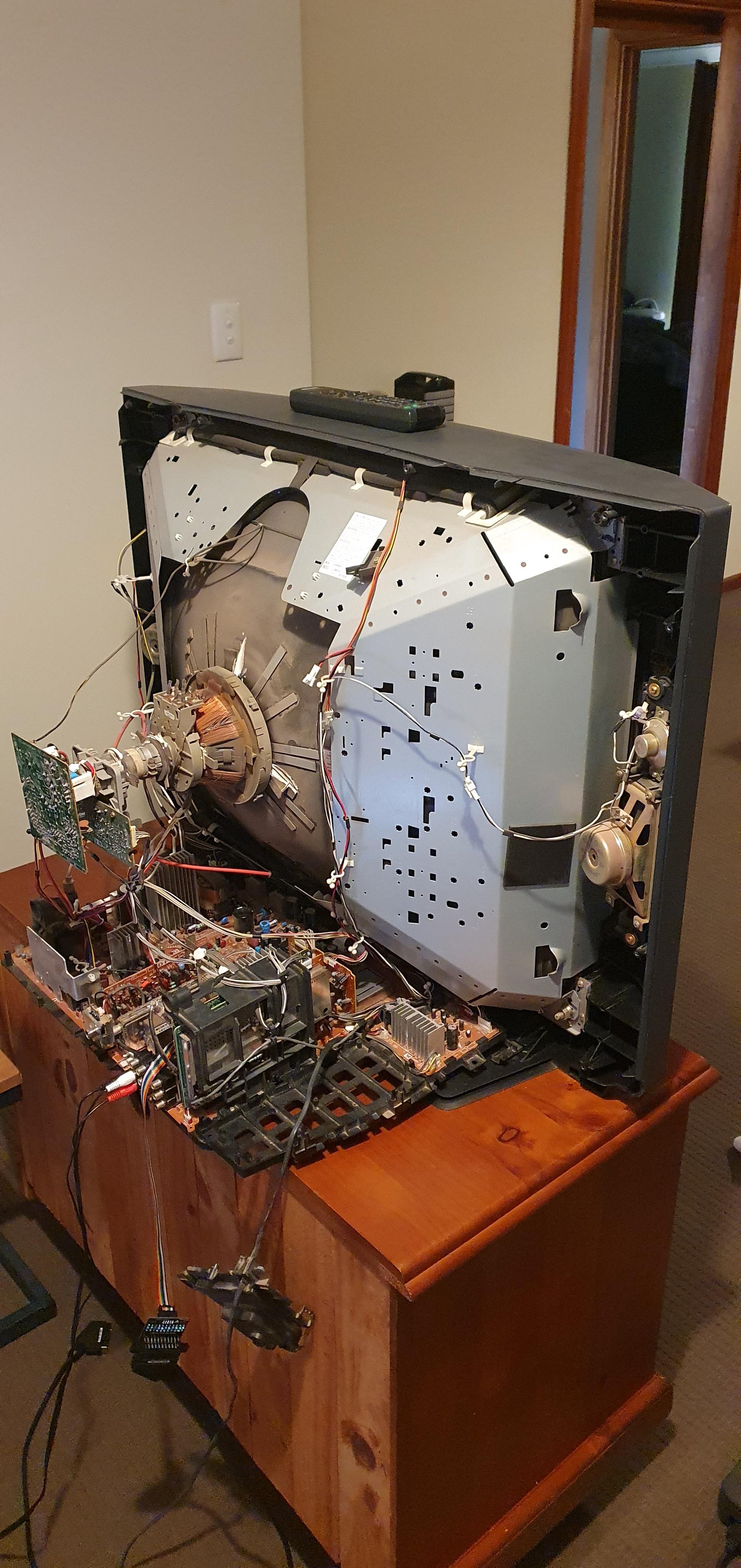
Now that you roughly know what needs to be done, prepare for the mod. Place the board on a comfortable place. Make sure you are not putting pressure on the flyback or other components. Taking out the chassis is fairly straight forward on this CRT. There are few wires that needs to be disconnected.
- Degauss wire
- Power wire
- Ground wire attached to the neck board
- Yoke deflection coil wire
- Anode wire (this is the one with the rubber cap)
- Left and right audio wires
Please remember that wires 1-5 are critical for the CRT to function and should not be omitted. Having any of these wires disconnected while powering up can damage the board and can have adverse effects.
It should also be noted, on this CRT, you can do the RGB mod by just taking out the A board. This means you don't even need to remove the anode wire.
Mux diagram
If you are building your own circuit, this diagram should help
While a second set of RGB input is available on CXA2050S, unfortunately on the BG-1L chassis it is disabled in software. There are I2C hacks that can potentially enable this input. However, we don't need to take this harder path. We can simply do a mux mod, which gives a stunning RGB picture.
STEP 1: Remove the following components
Remove the three (1.8 kΩ) ground resistors. These are marked as Cxxx for whatever reason instead of Rxxx.
- C325 (1.8 kΩ)
- C326 (1.8 kΩ)
- C327 (1.8 kΩ)
STEP 2: Connect RGB, Blanking and Ground
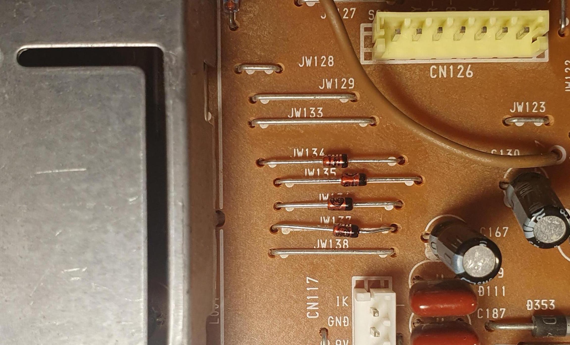
Replaced jumpers JW134, JW135, JW136, JW137 with diodes. Diode stripes should be pointing towards the chroma chip. The idea here is to make sure the external RGB input currents don't go towards the OSD chip. Instead these diodes make sure the current is directed towards the chroma IC (CXA2050S).
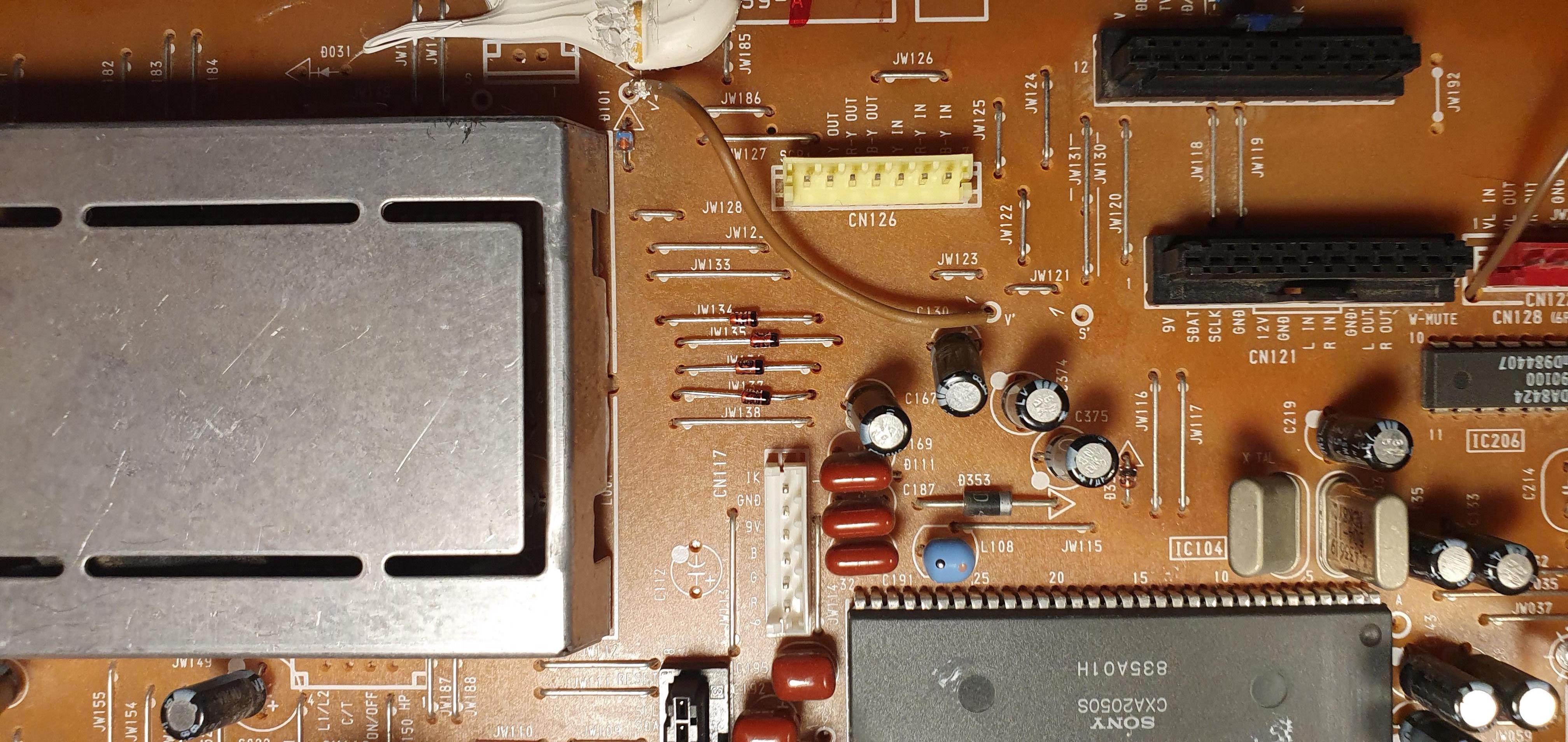
Red, Green, Blue, Blanking (Brown), Ground ![]()
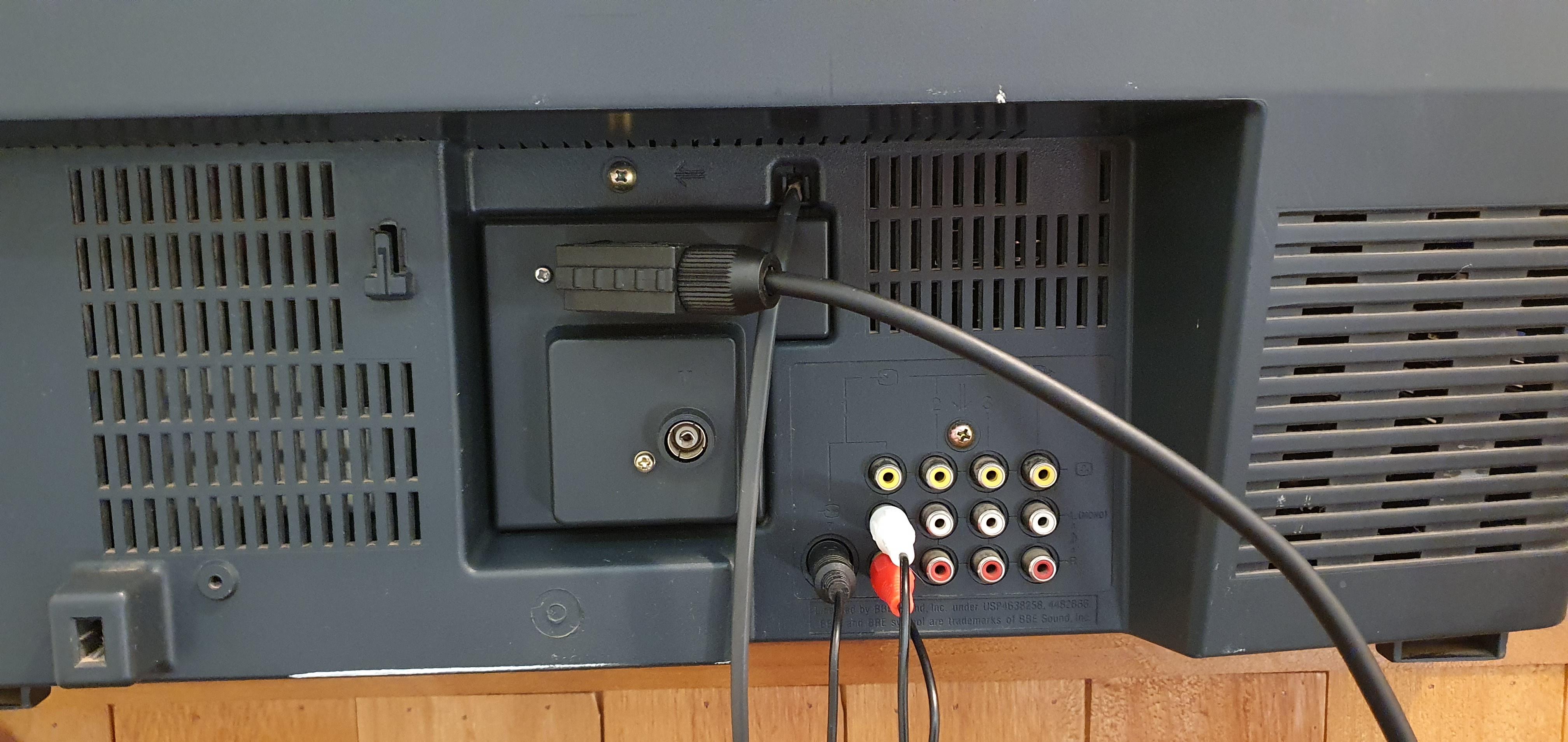
STEP 3: Connect Audio and Sync
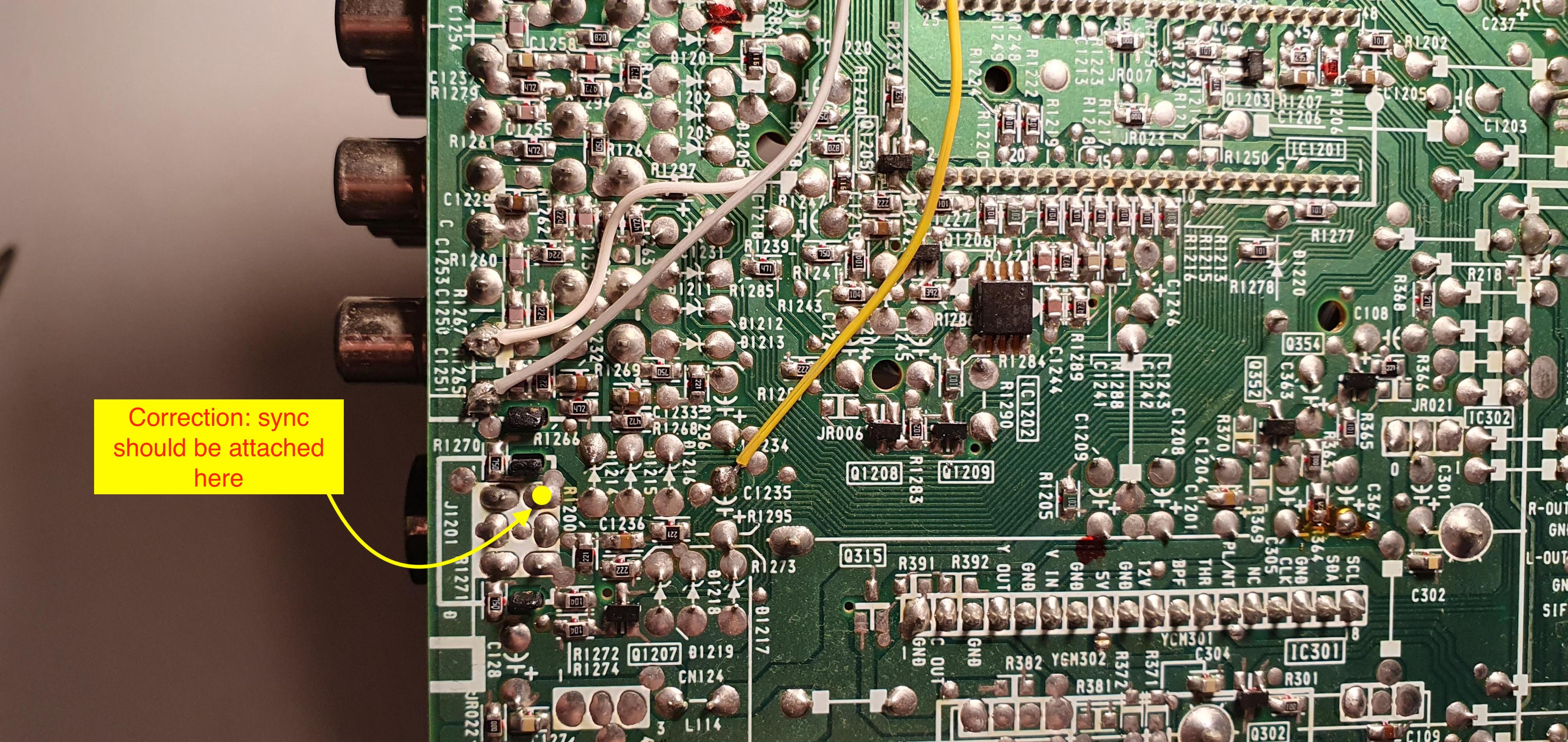
For stereo audio to work, both Video 1 audio left and right inputs should be populated. There is a physical switch inside the red RCA audio port that enables stereo. For sync to work through luma, S-Video port should be populated. When the S-Video port is populated, detect line is grounded signaling the video switch IC to use chroma/luma input instead of the composite video input.
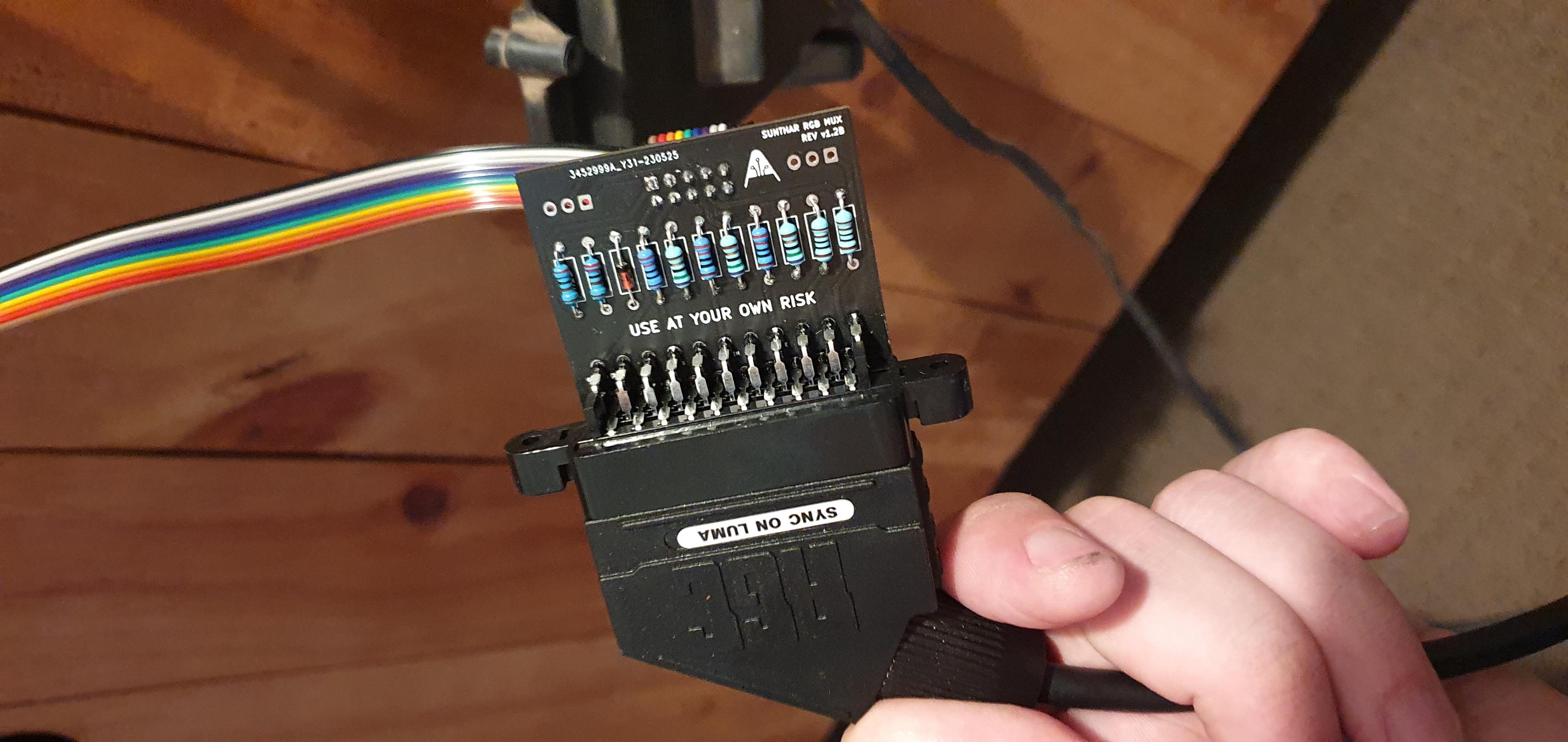
STEP 4: Build your mux board
This mod uses the RGB mux board. This is optional, but will make your mod easier and stable. You can also create the circuit presented in the schematics above without the board. Please also checkout the mux calculator to play with your own values.
| On Sony CRT Chassis | KV-LX34M31 |
|---|---|
| CRT RGB inline resistor | 1.2kΩ |
| 0.1μF caps replaced | No |
| Add diodes on chassis RGB lines? | Yes |
| Add blanking diode on chassis | Yes |
| RGB mux board | KV-LX34M31 |
|---|---|
| Mux board RGB termination (R1, R2, R3) | 75Ω |
| Mux board RGB inline resistors (R4, R5, R6) | 180Ω |
| Mux board Audio LR (R7, R8) | 1kΩ |
| Mux board blanking diode (R9) | 1N4148 |
| Mux board blanking ground resistor (R10) | open |
| Mux board blanking resistor (R11) | 2.2kΩ |
| Mux board transistor base resistor (R12) | 1kΩ |
| Mux board transistor (Q1) | PN2222A |
Compatible mux boards:
STEP 5: Attach the female SCART connector to TV
Creating a SCART cutout and mounting it is an art. I have a dedicated section for it. How to create and mount a SCART female plug?
This SCART port was cut a bit rough. You can make the SCART port look smoother with a file. 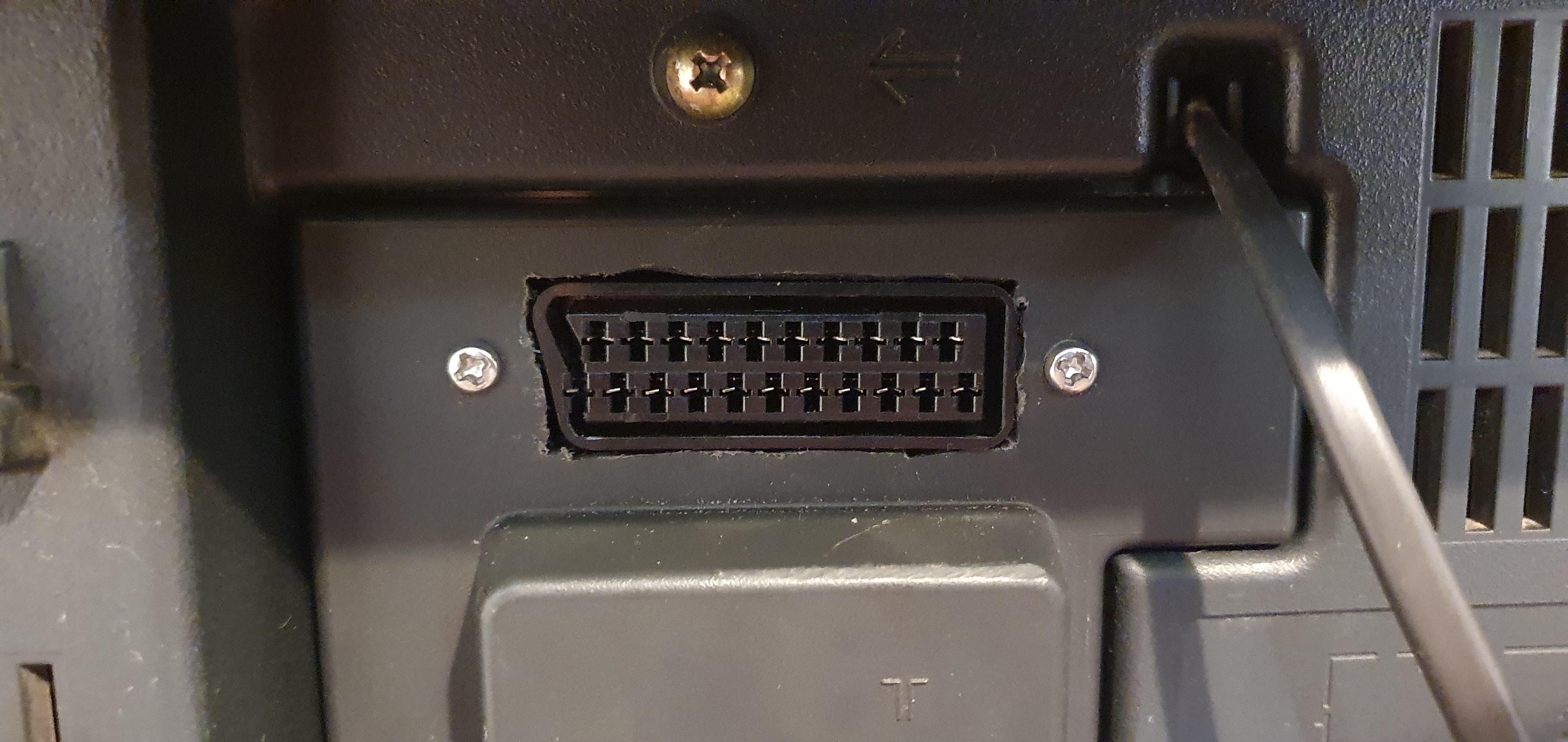
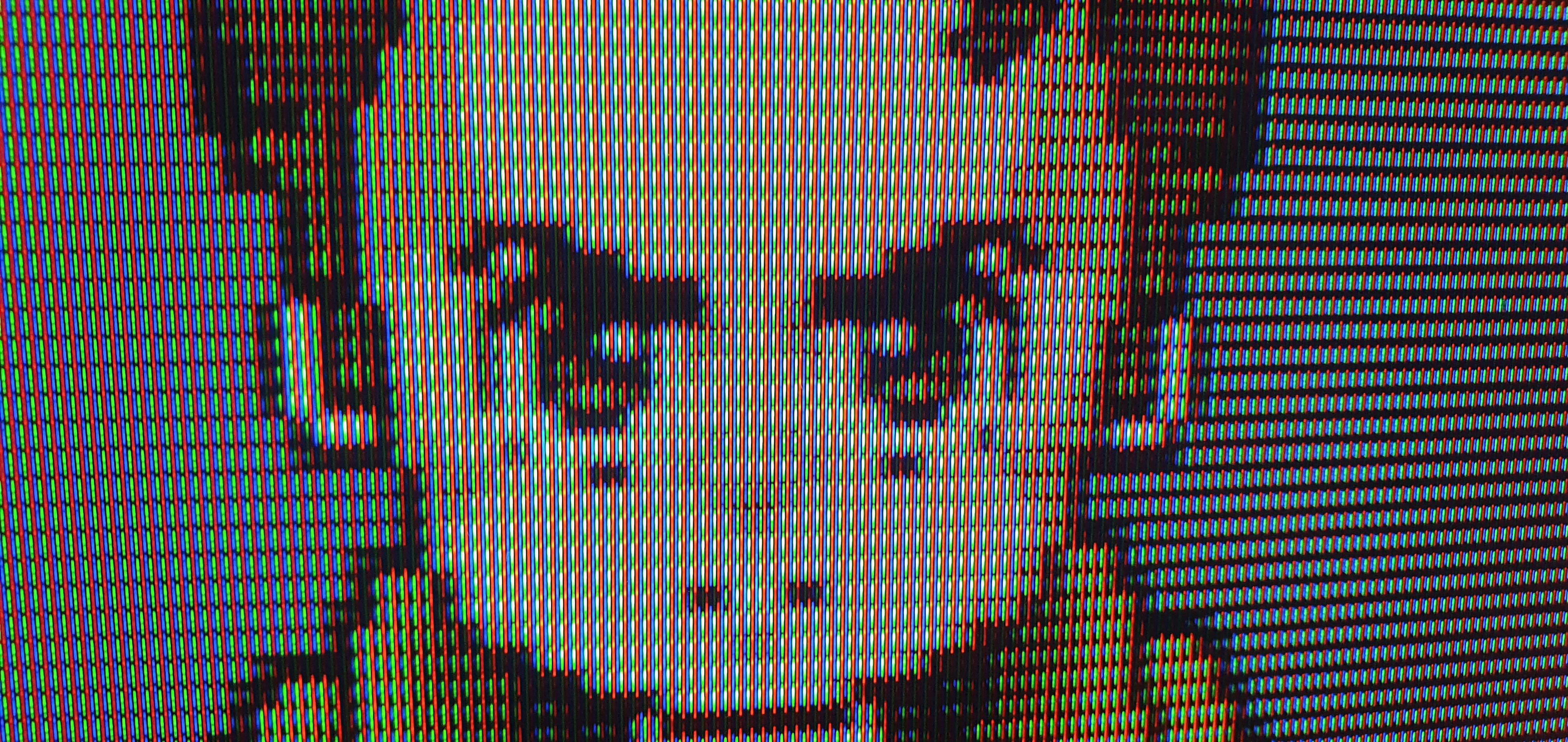
Games
PS1 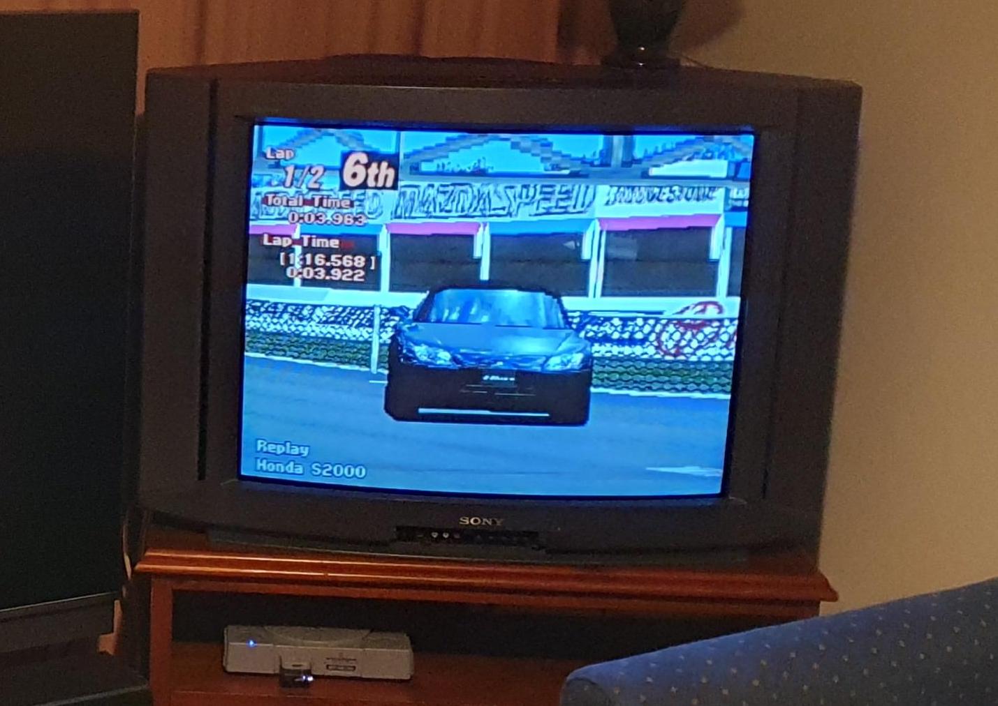
PS1 - Spyro The Dragon 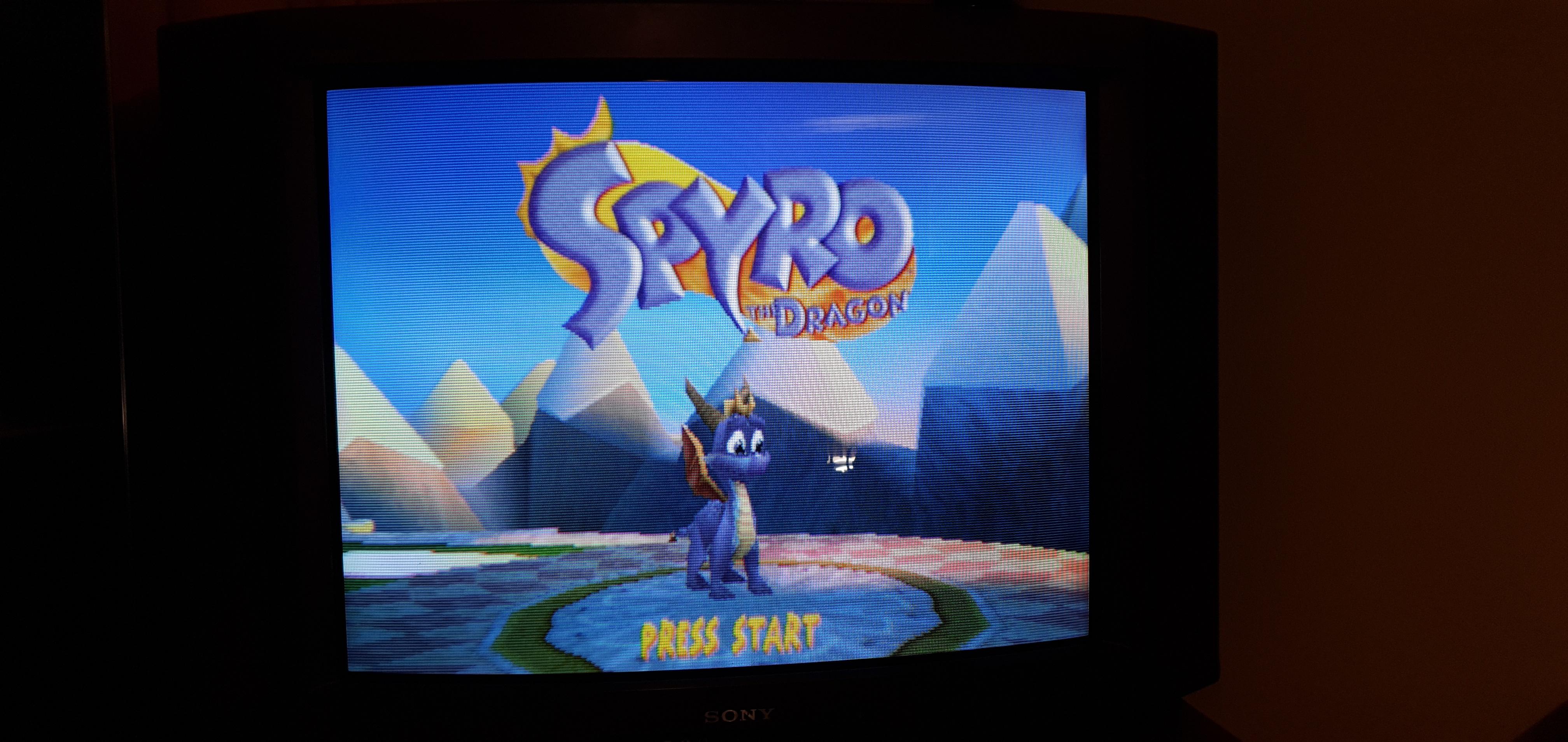
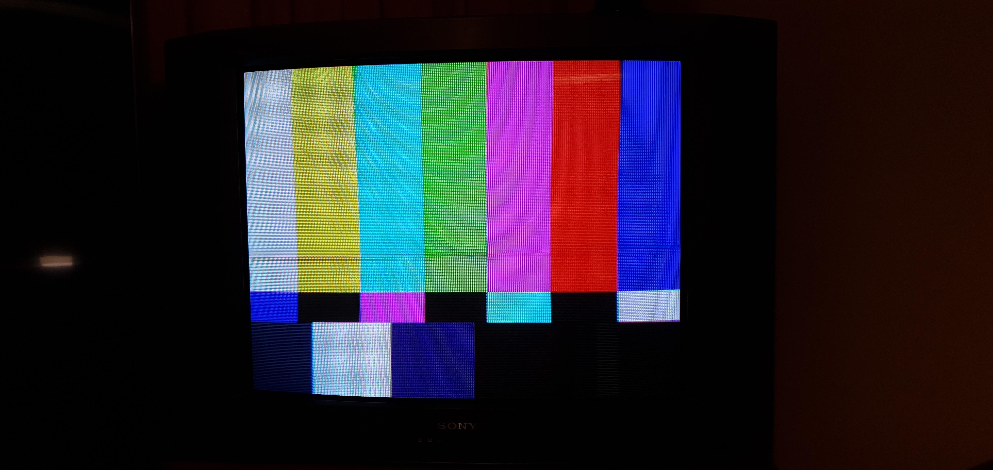
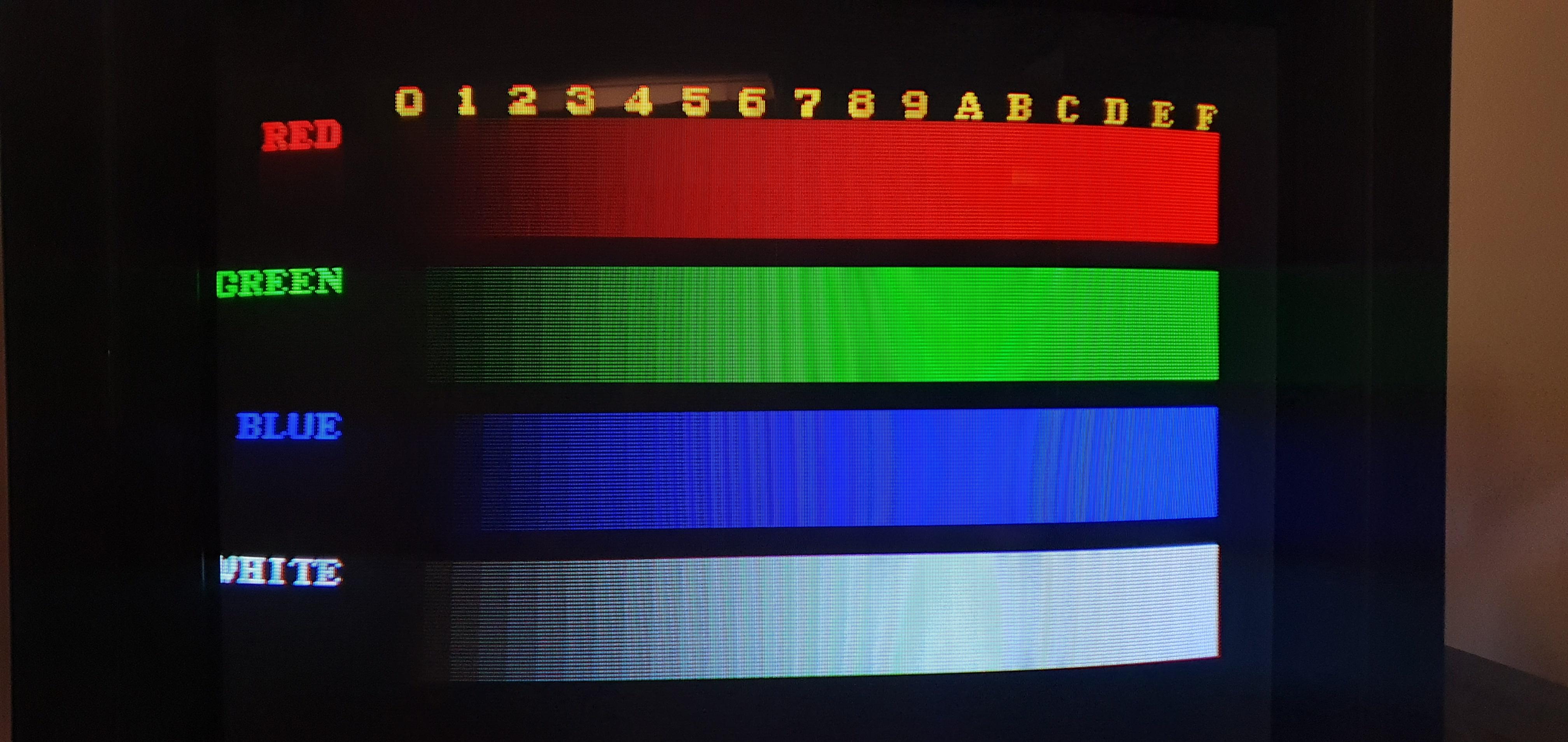
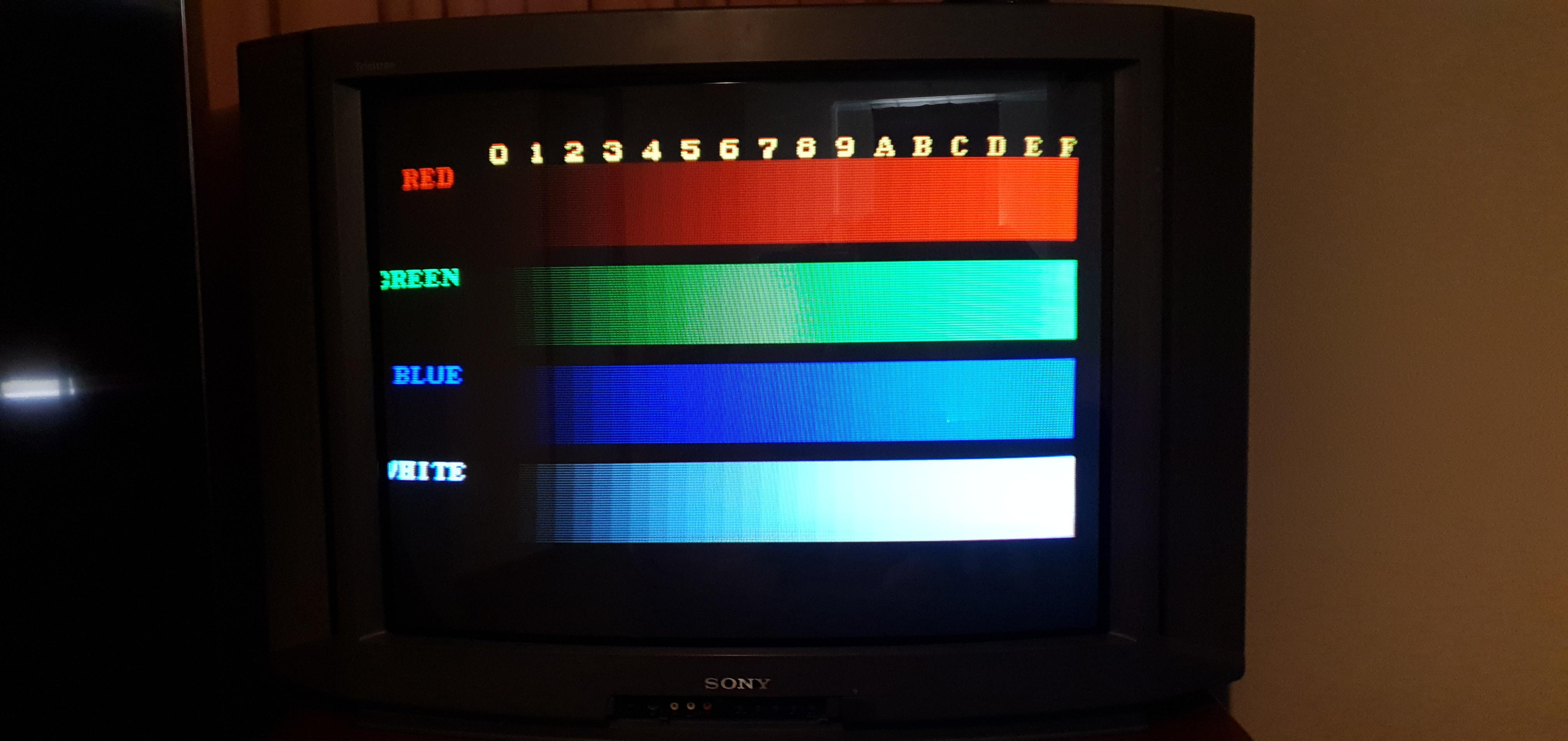
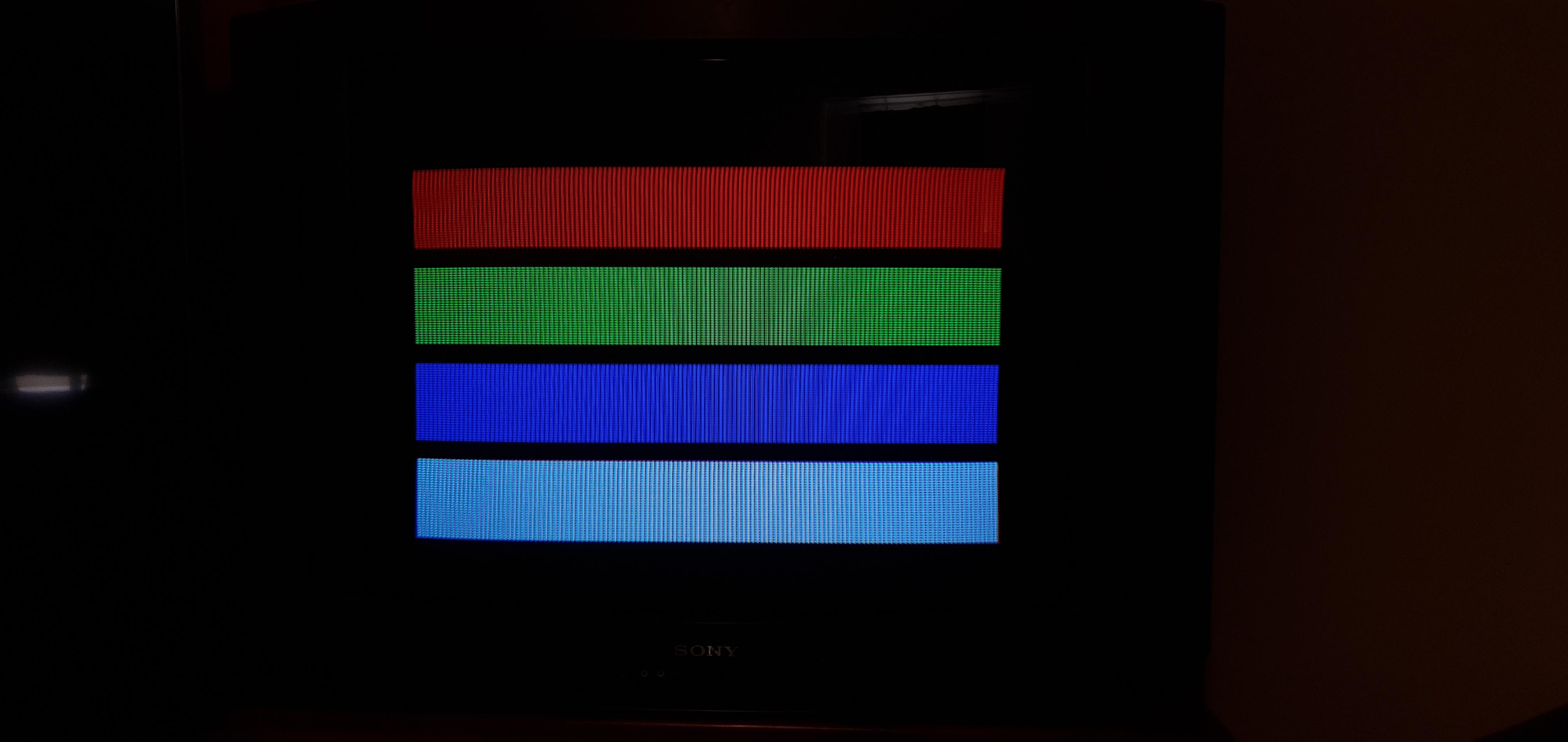
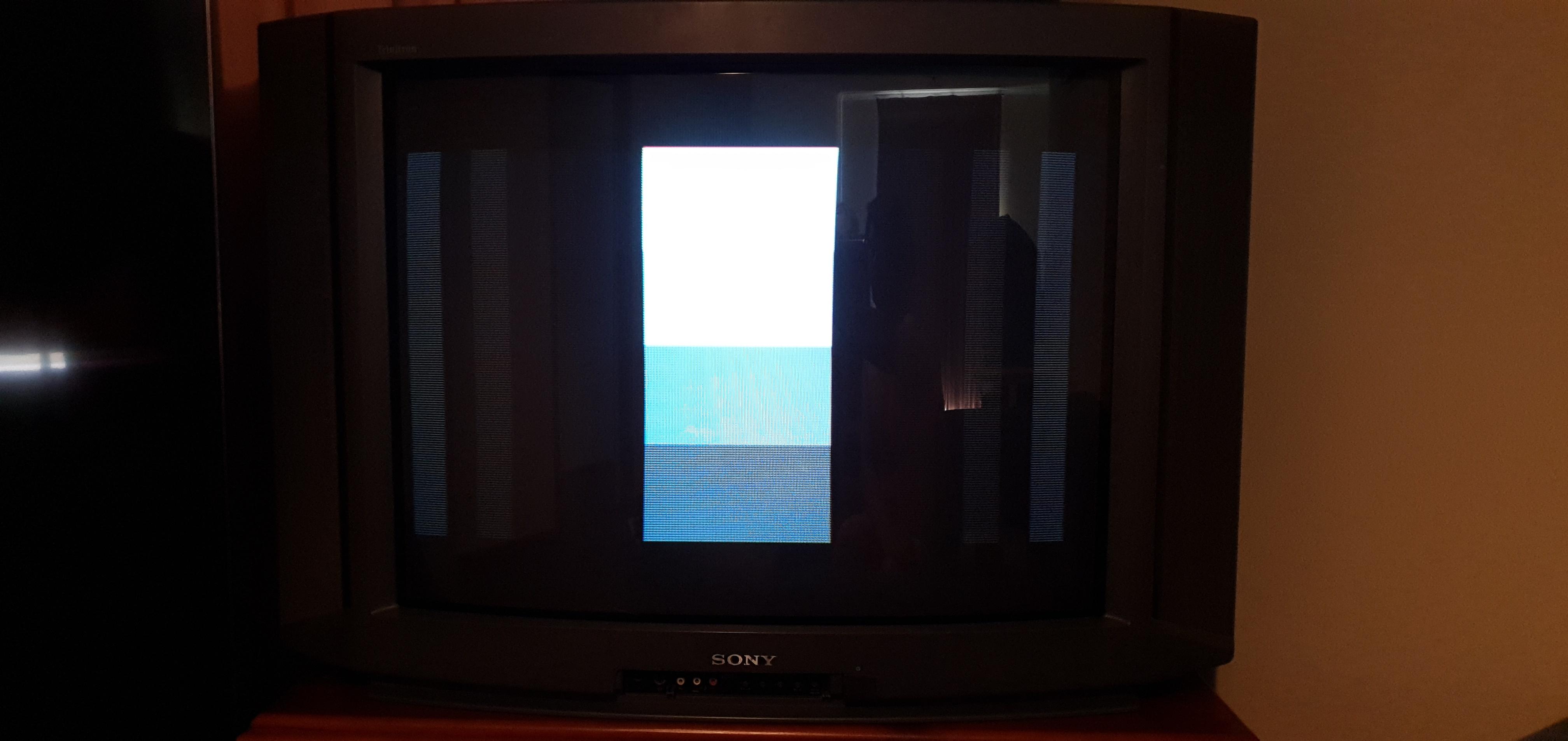
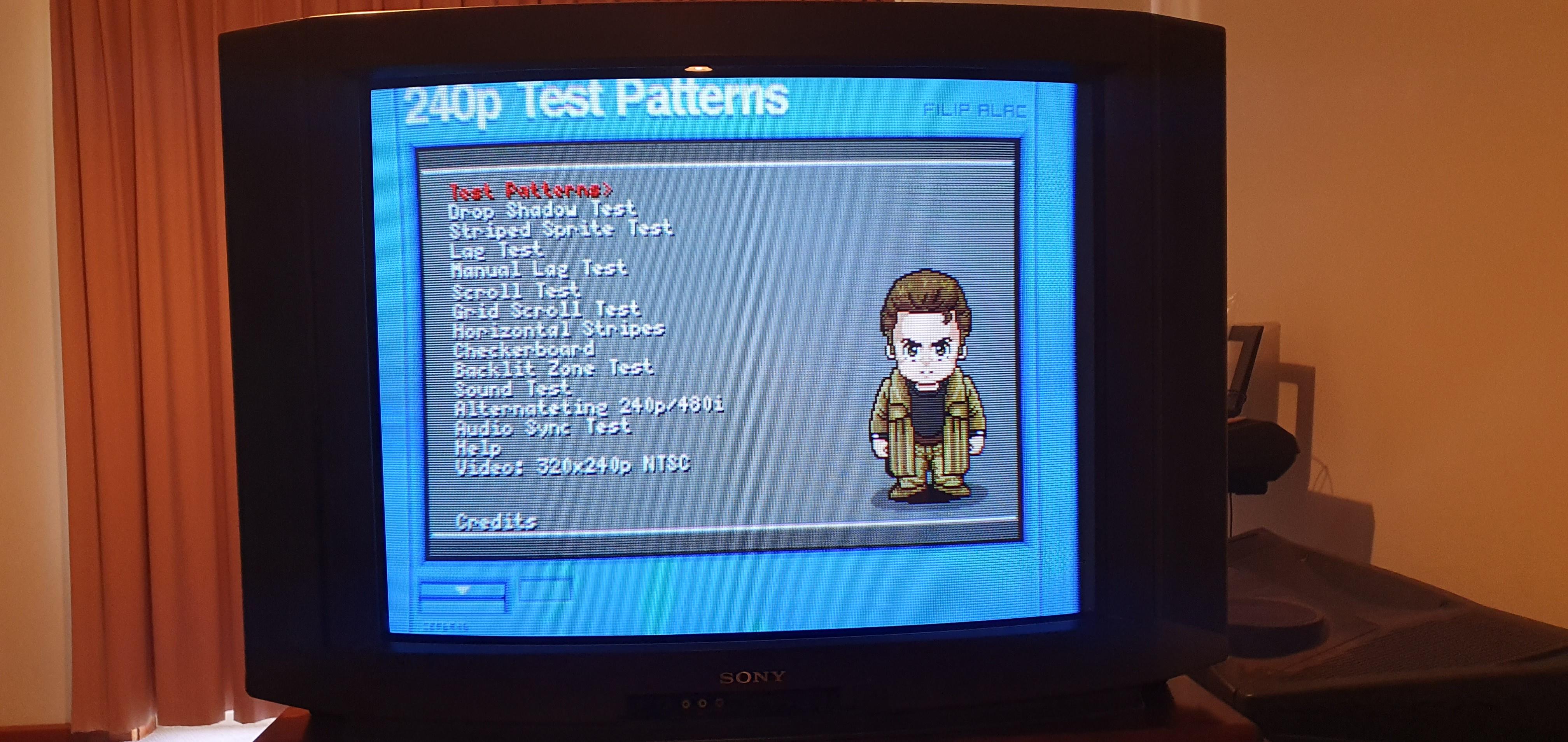
Patterns
Pictures taken before HPOS adjustment 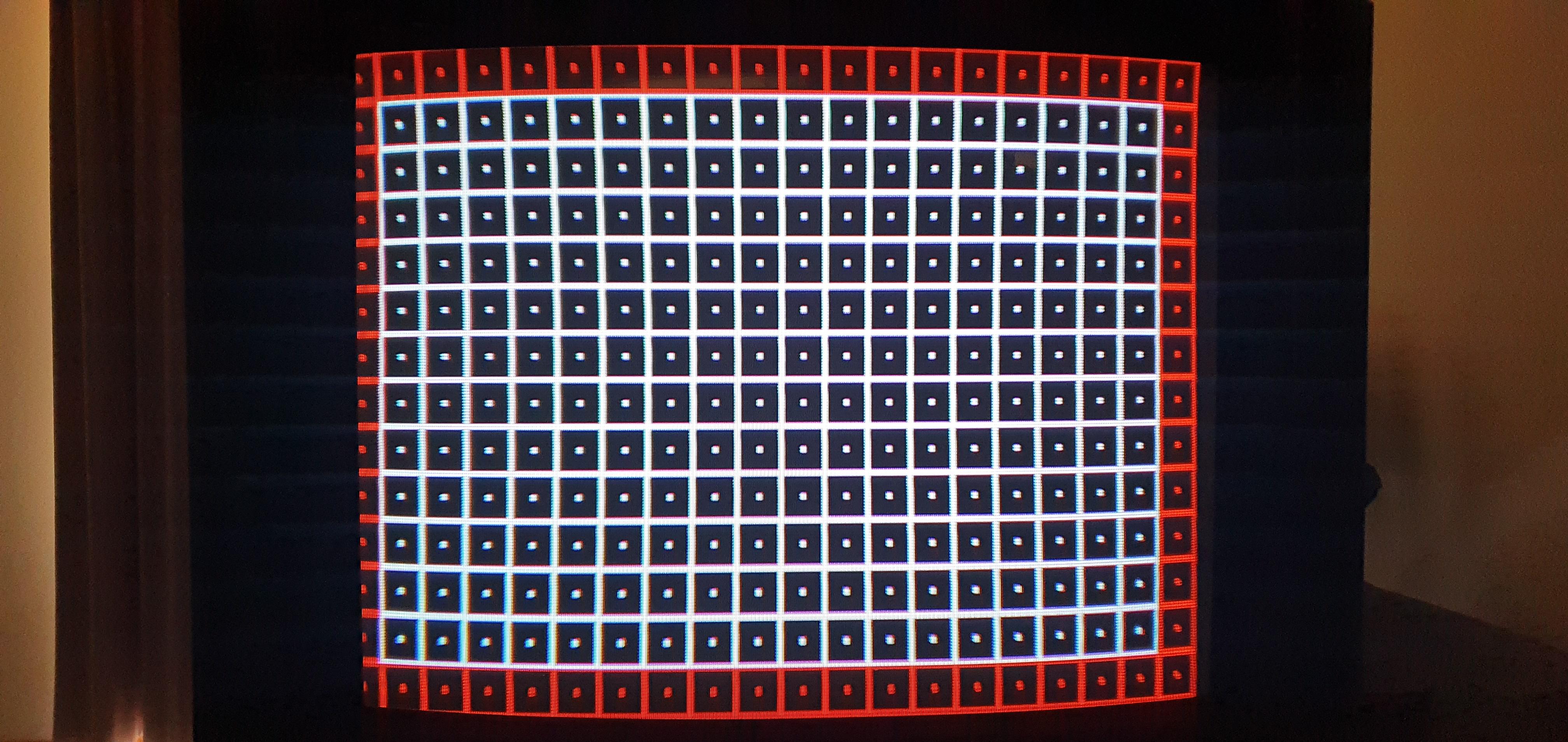
Pictures
A Board 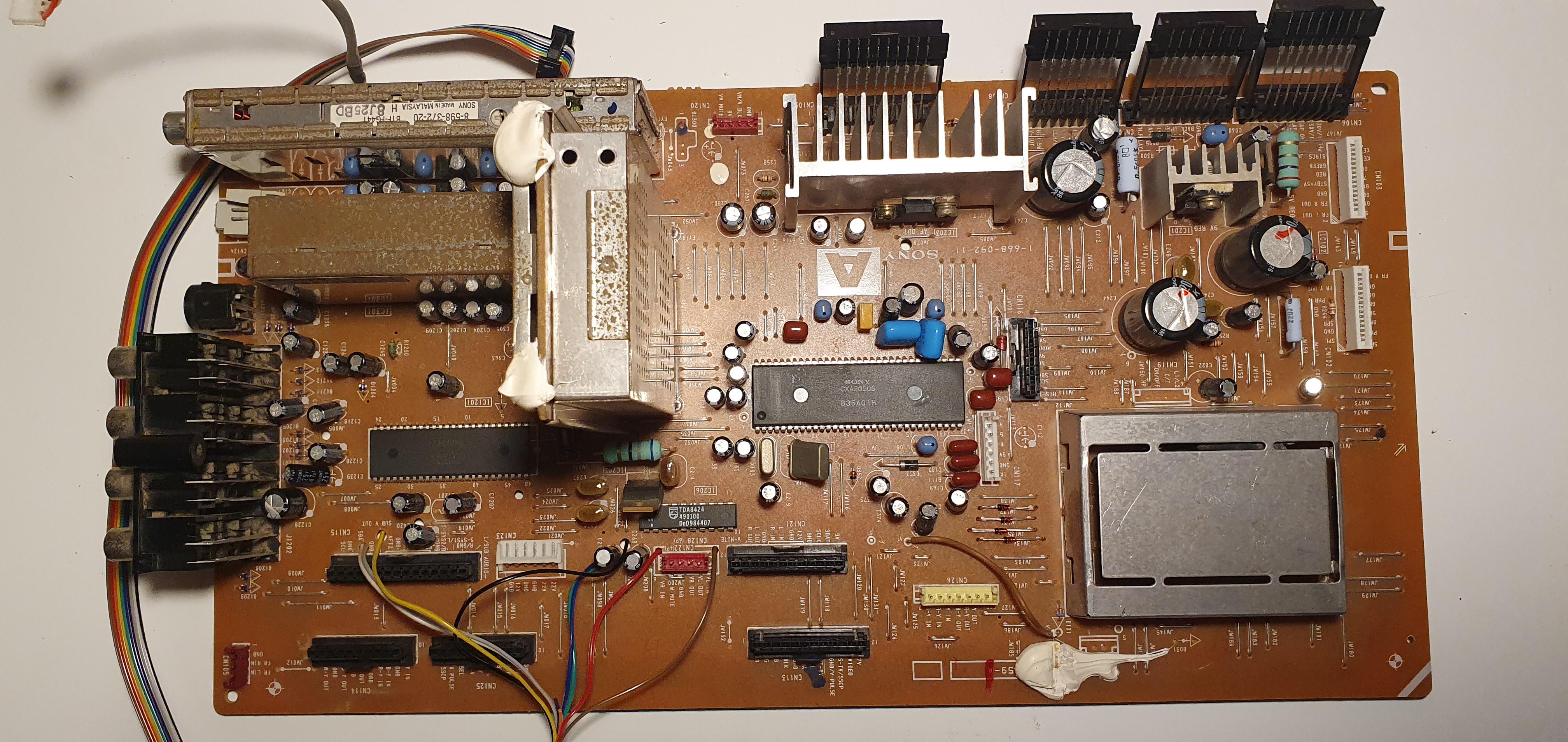
Back 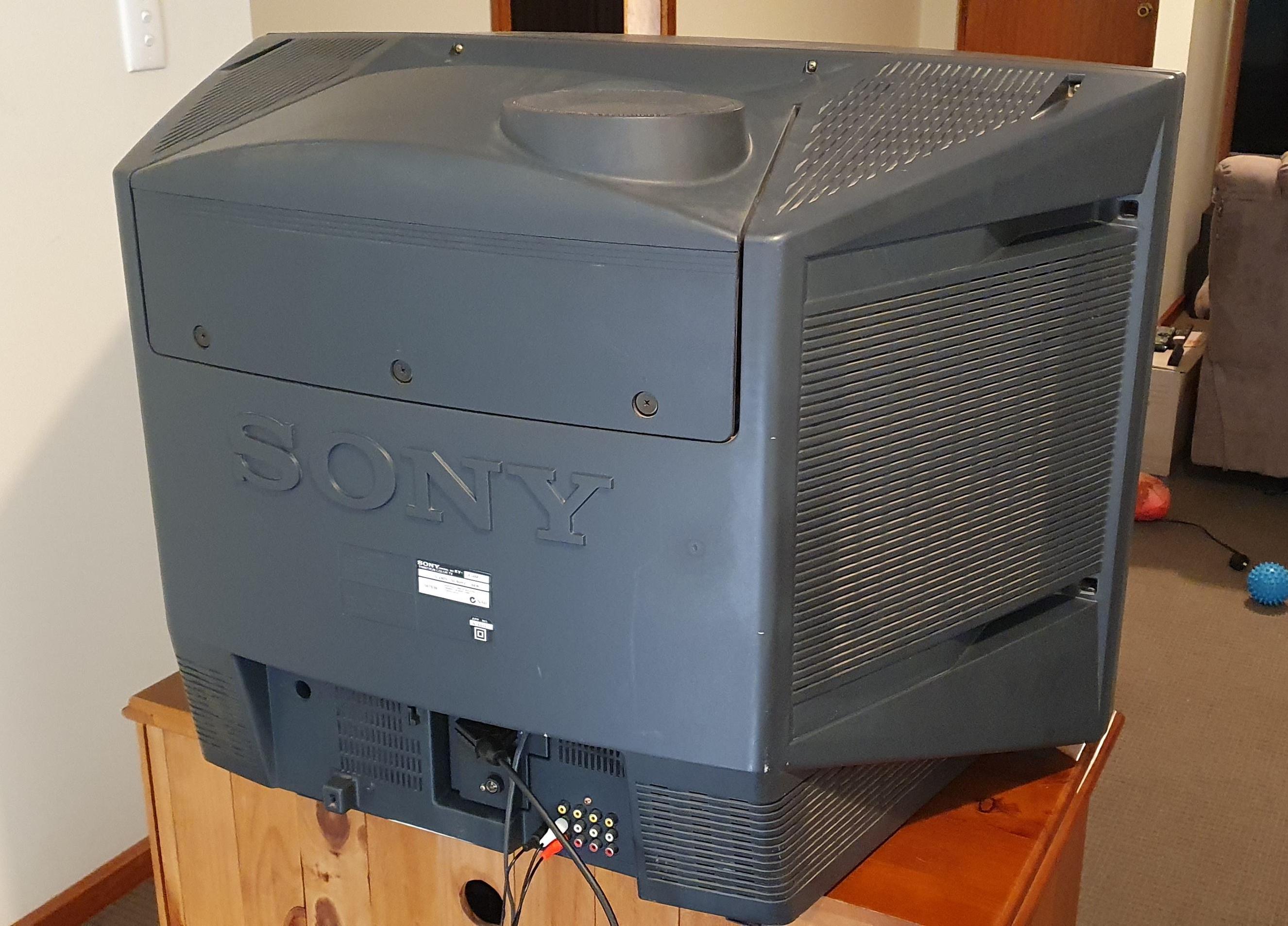
Back Label 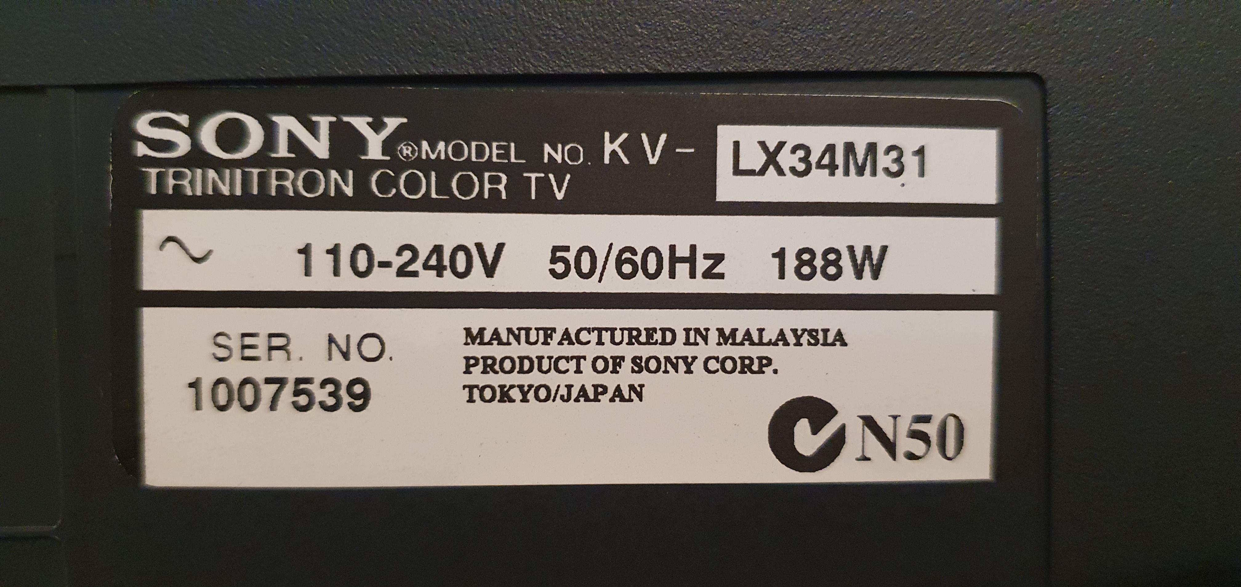
Tube