Toshiba 27A35
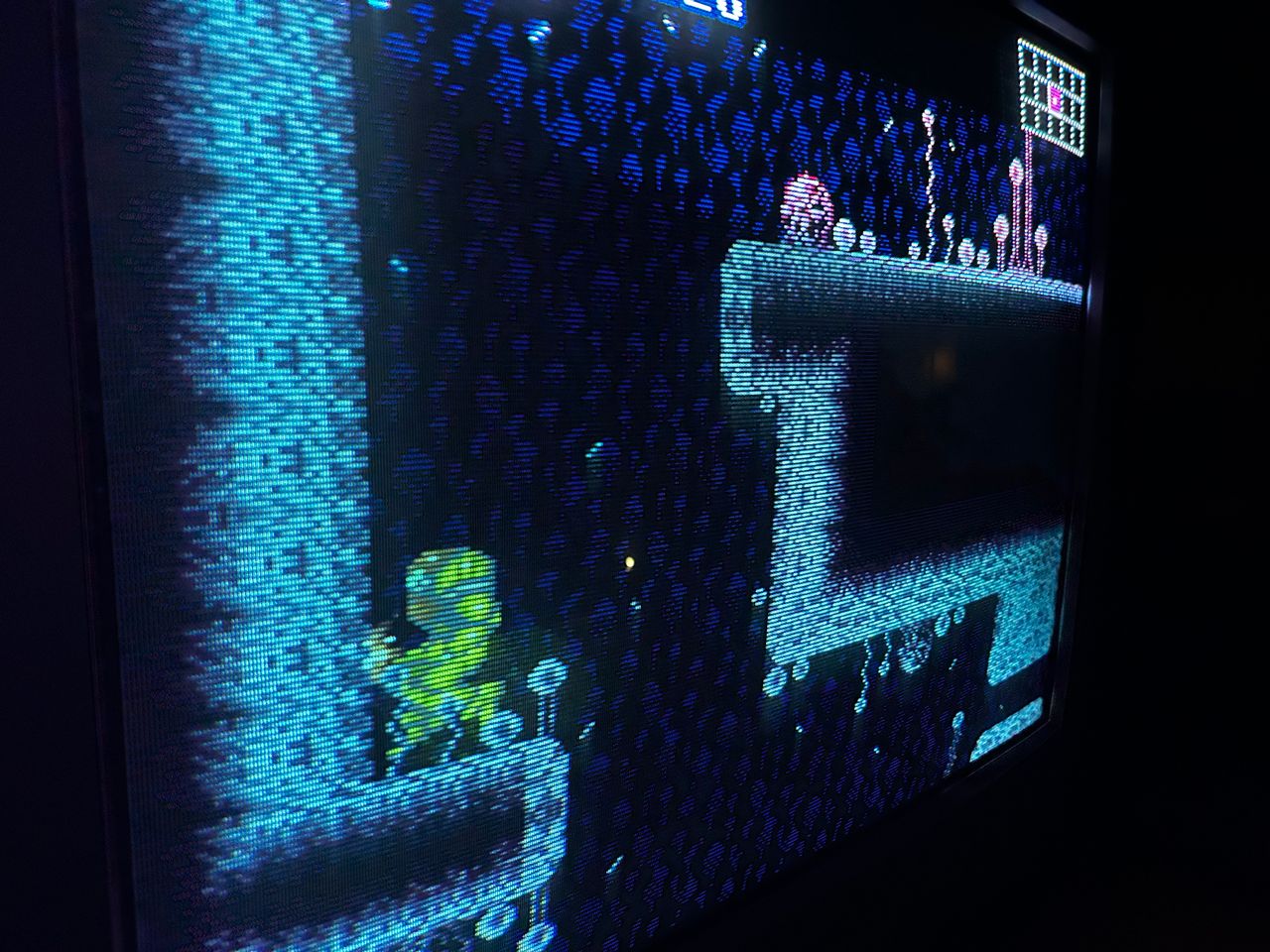
Toshiba 27A35 CRT RGB mod
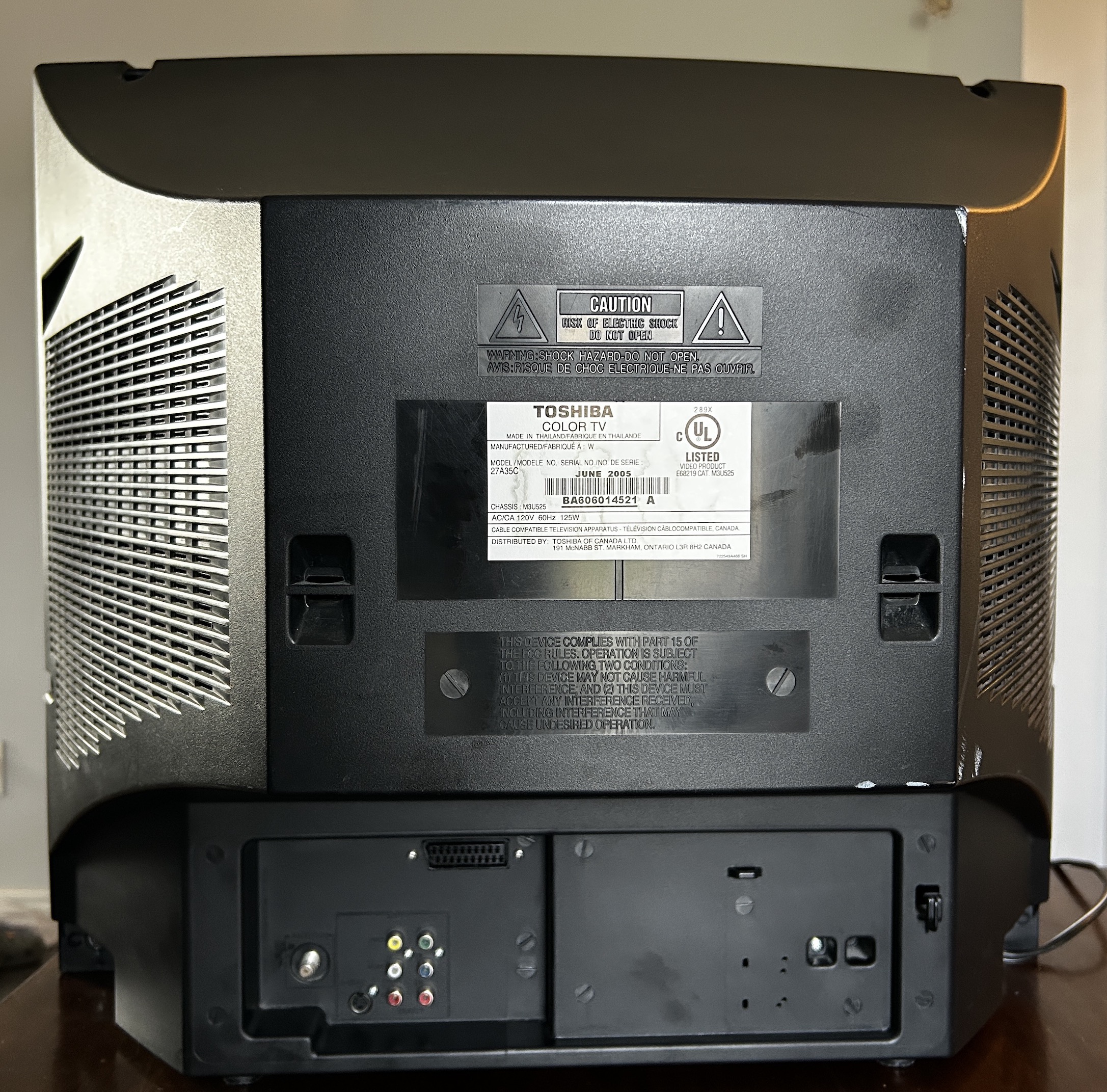
The Toshiba 27A35 is a 27" curved CRT television released in 2005, with the last digit of the model number indicating the release year.
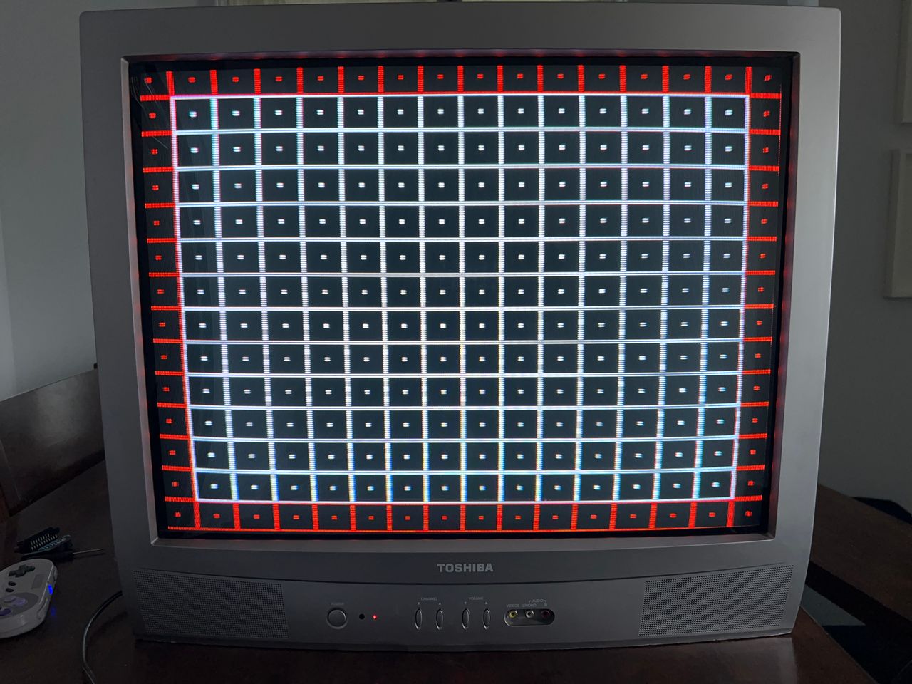
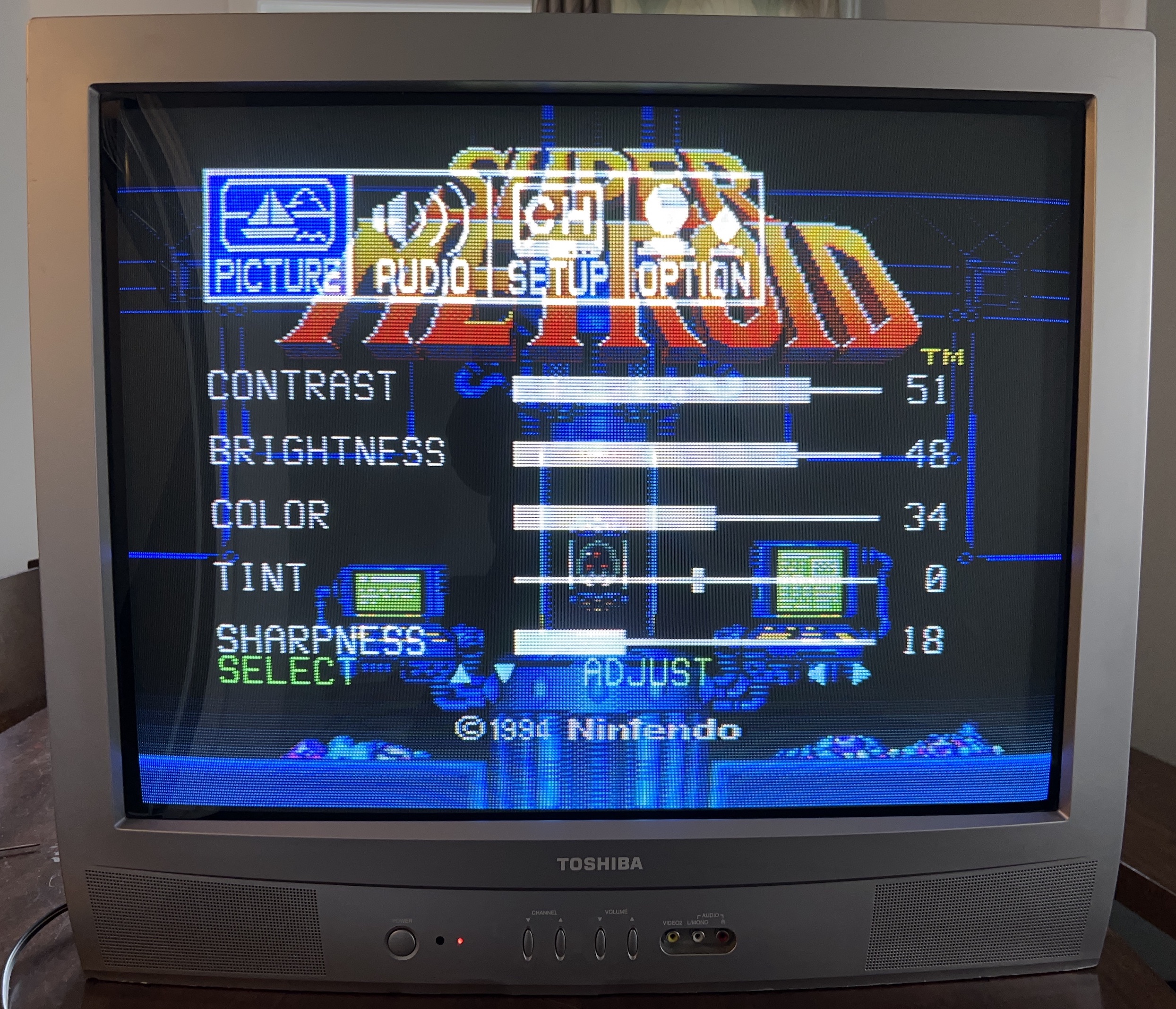
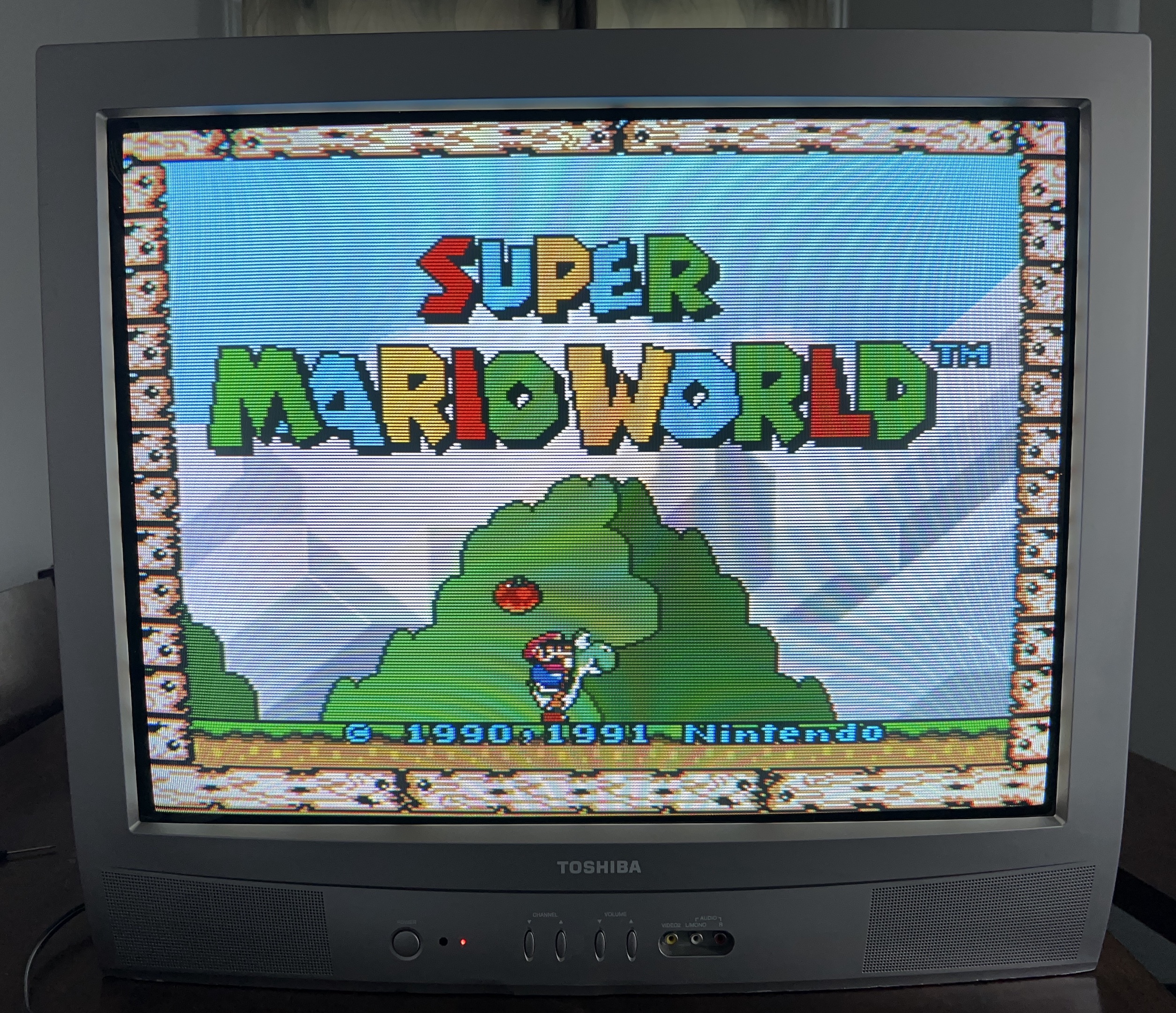
The curved CRT screen delivers excellent geometry and sharp picture quality. This television features component video inputs and allows users to monitor the number of hours the tube has been in use, provided the counter has not been reset. The 27A35 offers superior geometry and reduced distortion compared to flat-screen alternatives and is RGB modifiable.
View full CRT details and more mod examples →
This is similar to Toshiba 27A34, but the location of jumpers and resistors removed etc. are all different. I also chose to permanently set this up for stereo, so that no dummy plugs are needed. I'm fairly impressed with this Toshiba compared to JVC D-Series and several 27" flat Trinitrons that fail to deliver similar convergence, geometry and lineraity. Horizontal linearity and scroll was amazing on this tube.
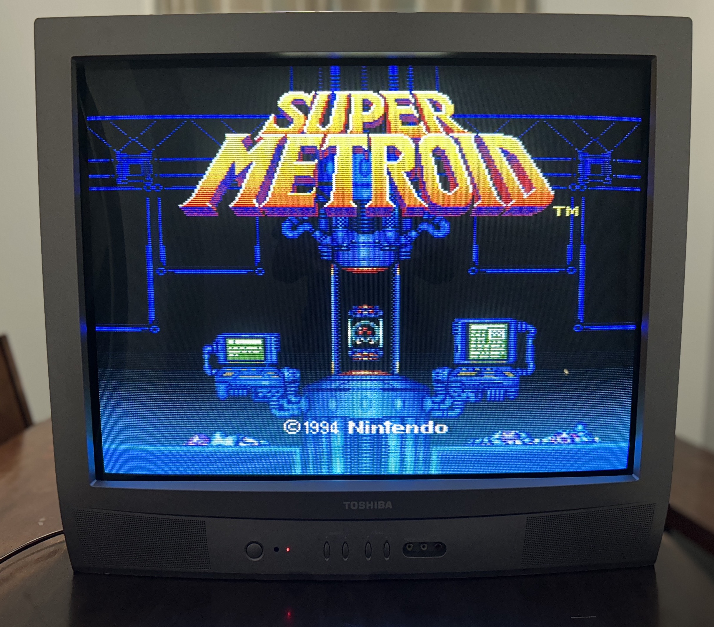
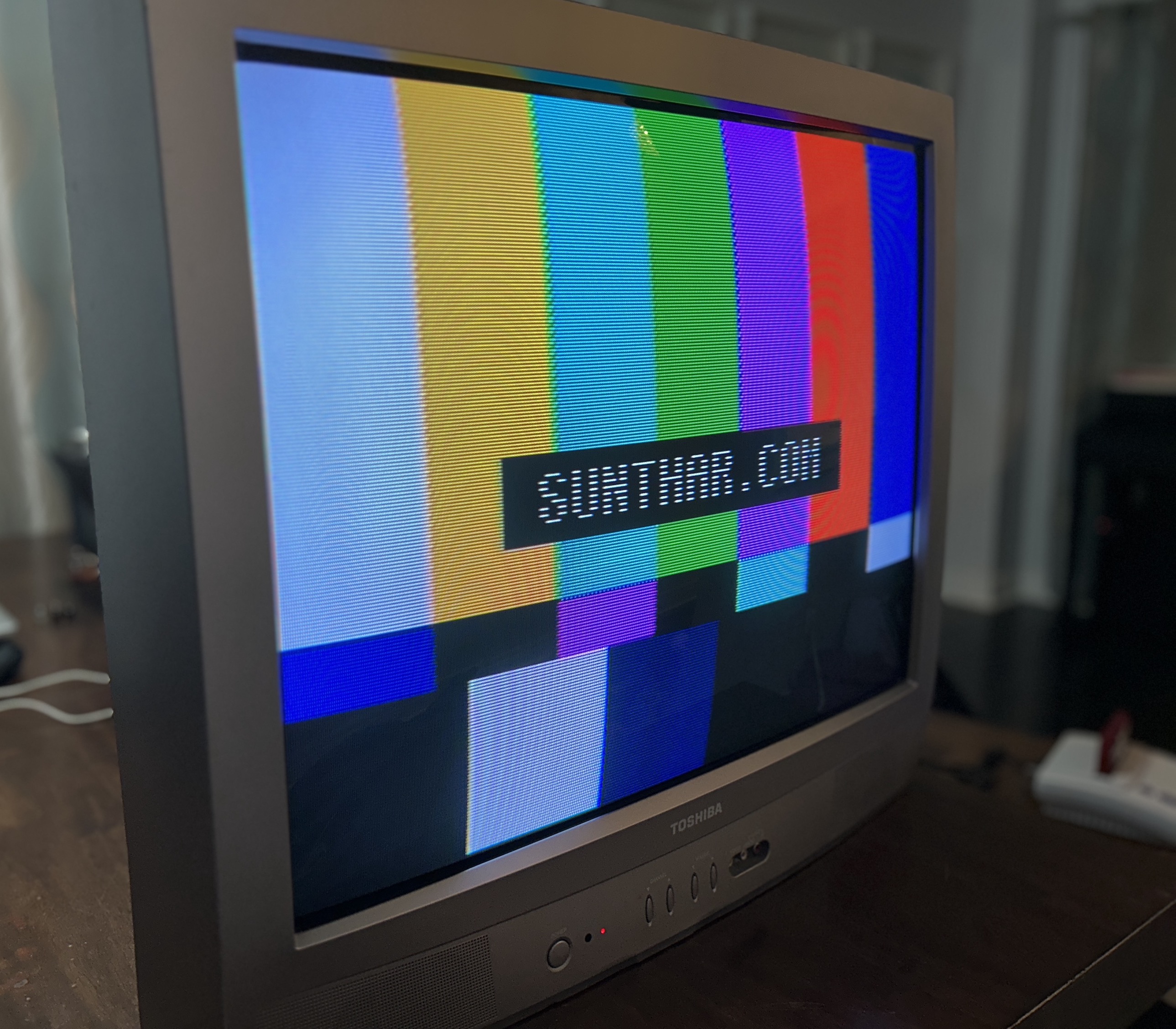
Table of Contents
Contributors
Thank you to everyone who contributed to this guide:
- Sunthar — author, RGB mod and pictures
CRT safety
Caution
You can die doing this! So read carefully! CRT TV is not a toy. Do not open a CRT TV. If you don't have any prior knowledge about handling high voltage devices, this guide is not for you. CRT TV contains high enough voltage (20,000+ V) and current to be deadly, even when it is turned off.
Plan of attack
Manuals and Datasheets
Specs
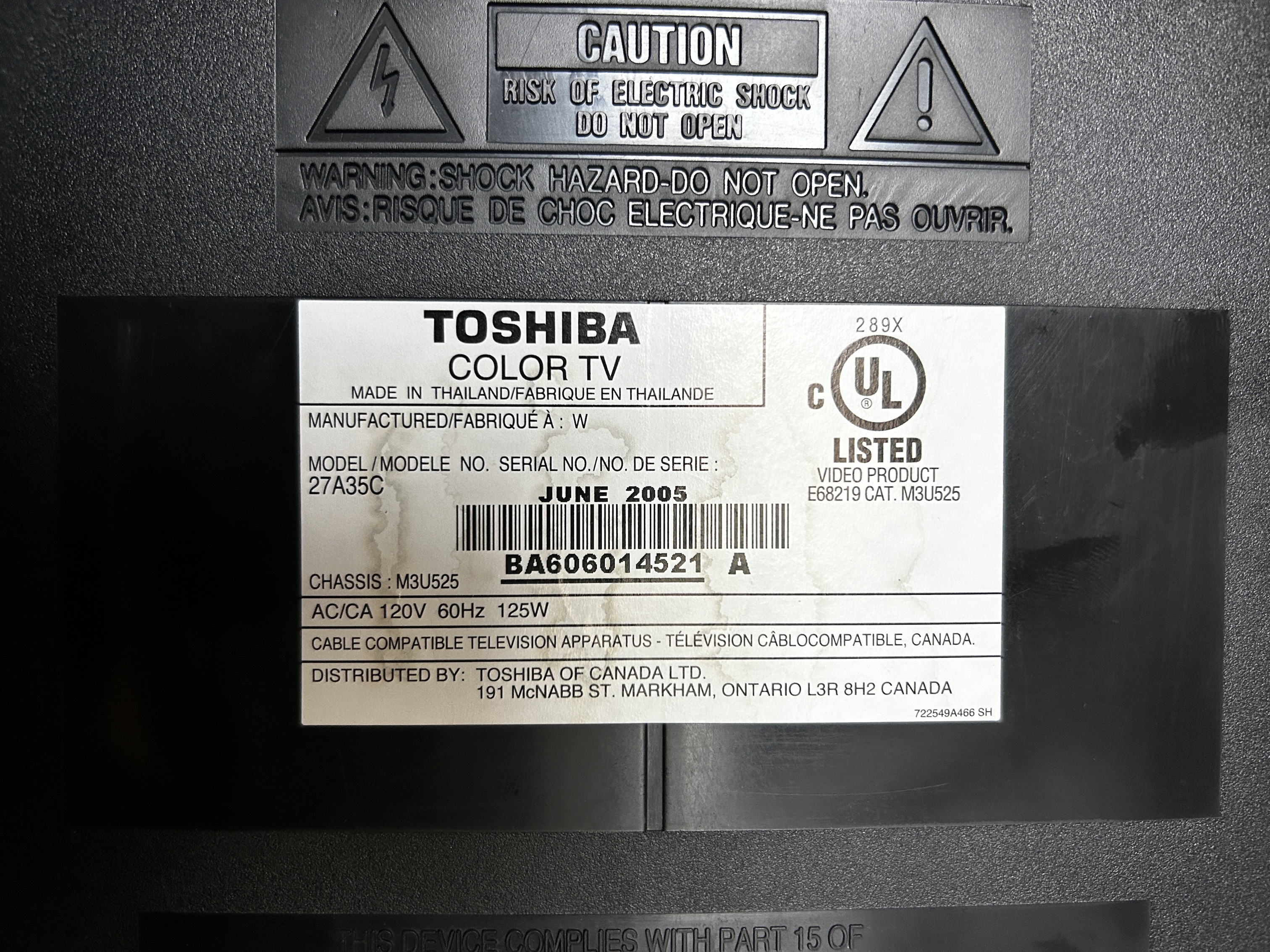
- Manufactured: Thailand (2005)
- Chassis: M3U525
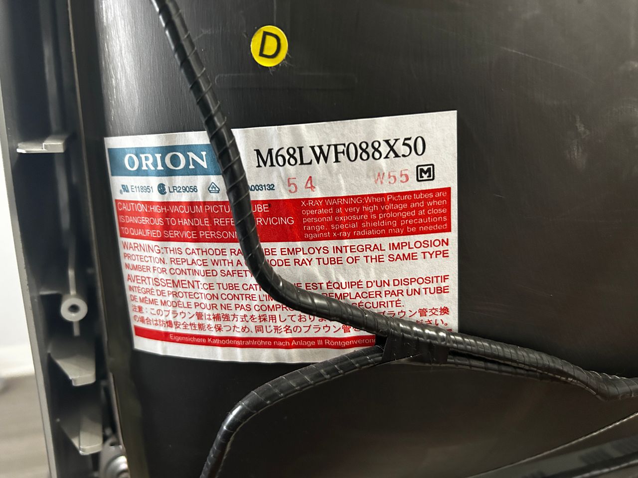
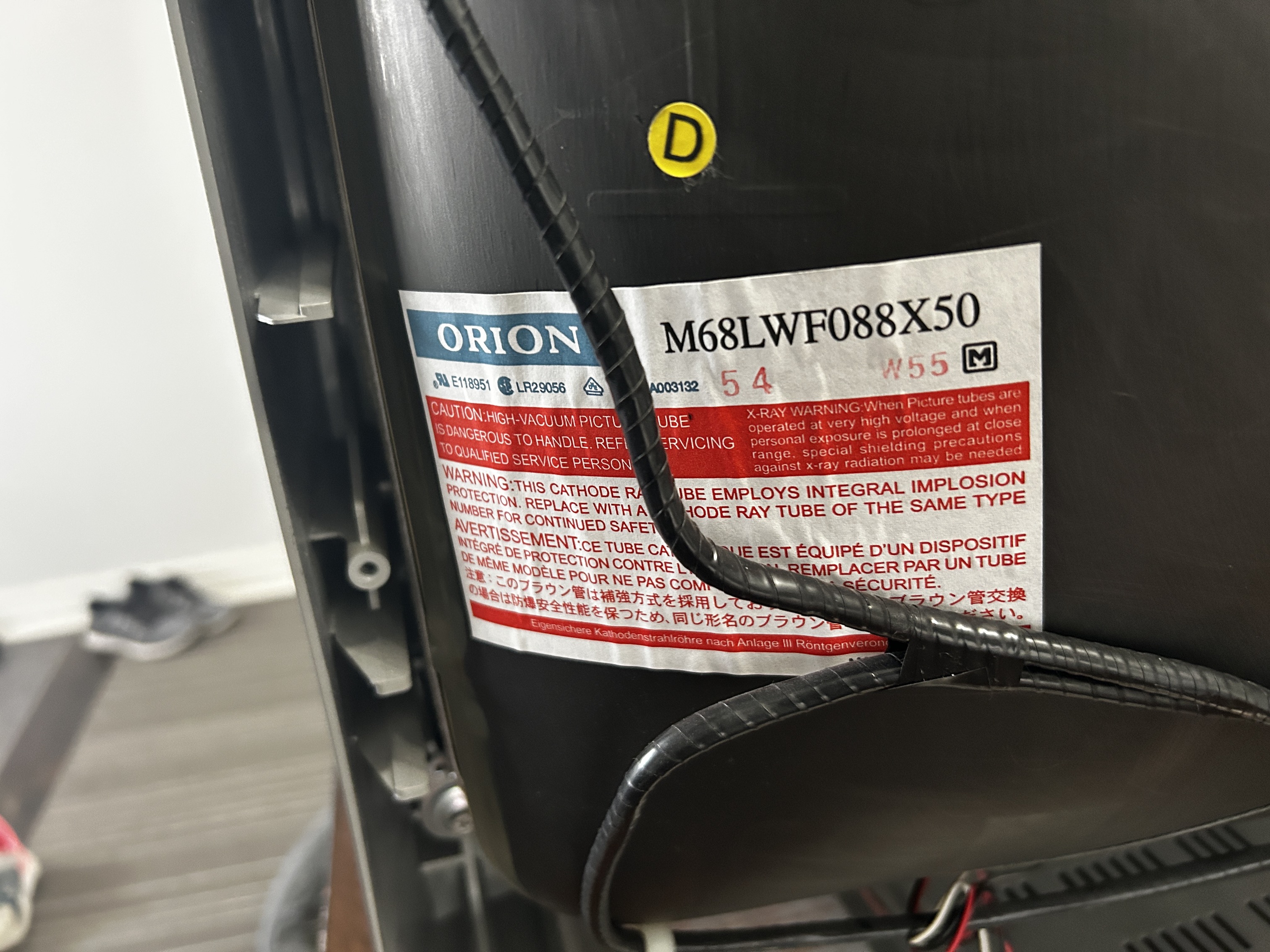
- Tube: Orion M68LWF088X50
- Jungle Chip: Renesas M61283BFP
- OSD Chip: Orion OEC7090B
- Screen Size: 27"
- Power: 125 W
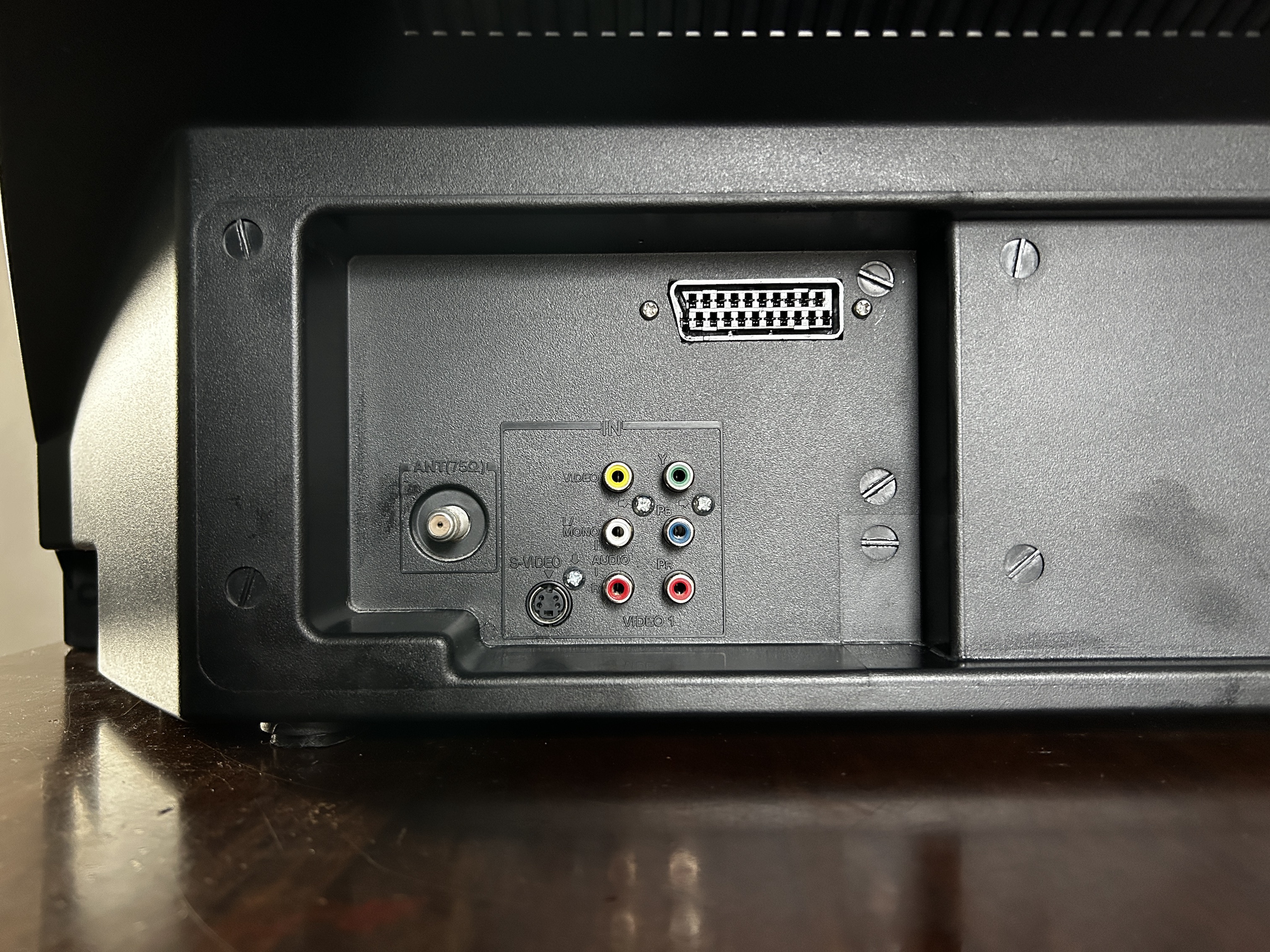
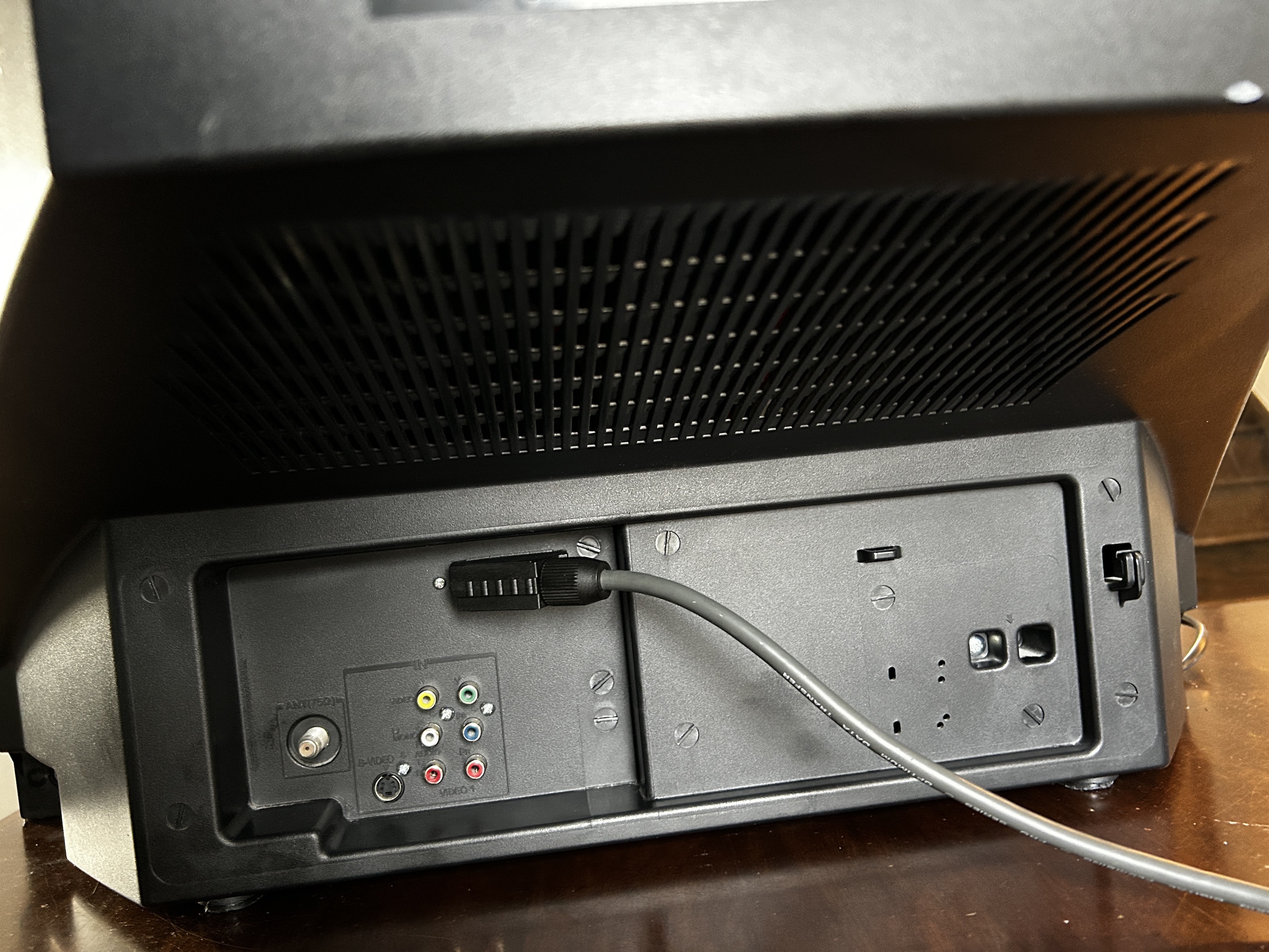
- Inputs: RF, Component YPbPr, Composite, S-Video
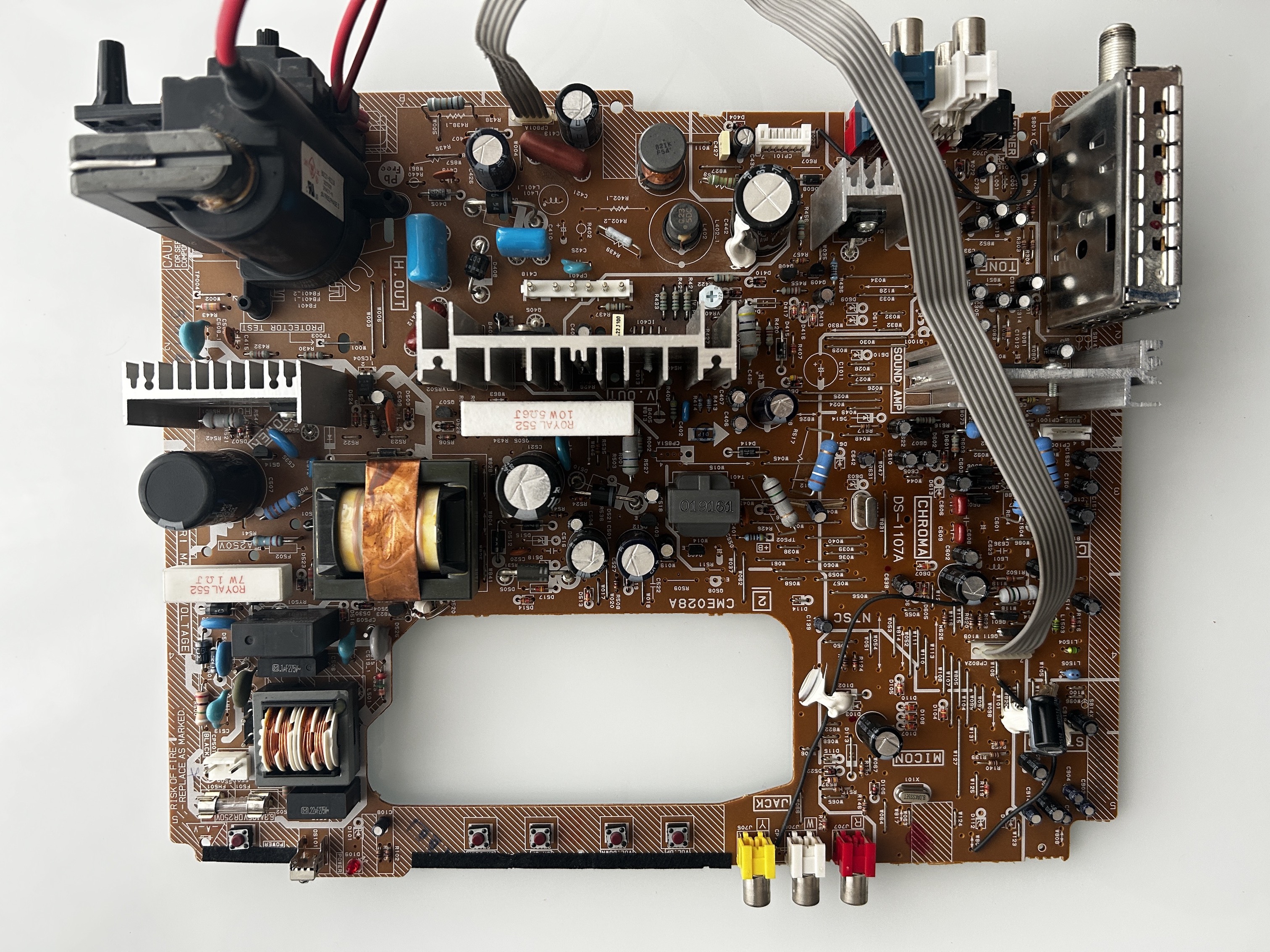
Chassis
Schematics
Get hold of the schematics/service manuals for your TV. Understand where the RGB and Fast Blanking signals go from OSD to the Jungle (Chroma) chip.
RGB mux diagram
Prepare the mux diagram. If you are building your own circuit, this diagram should help.
Performing the mod
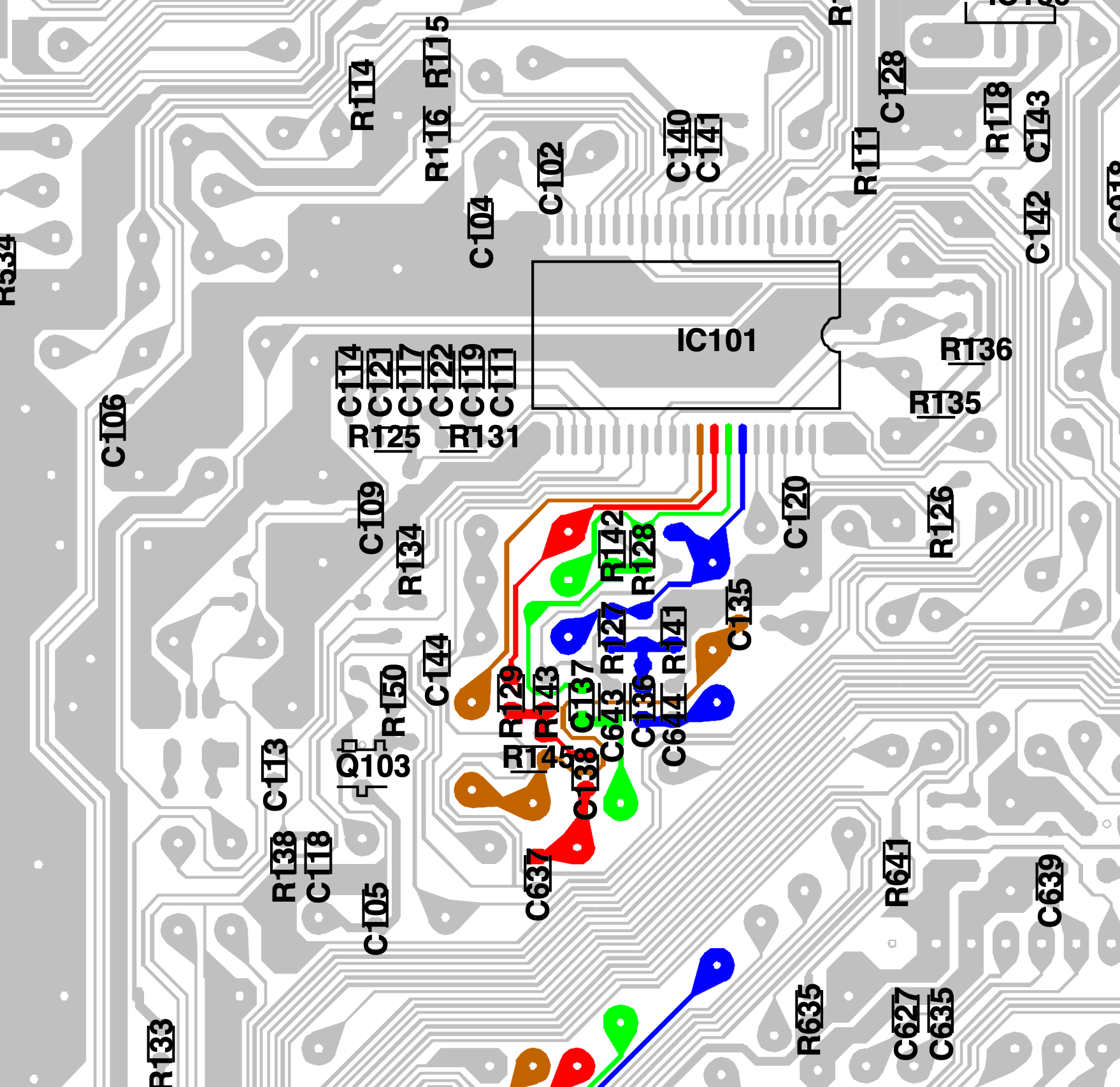
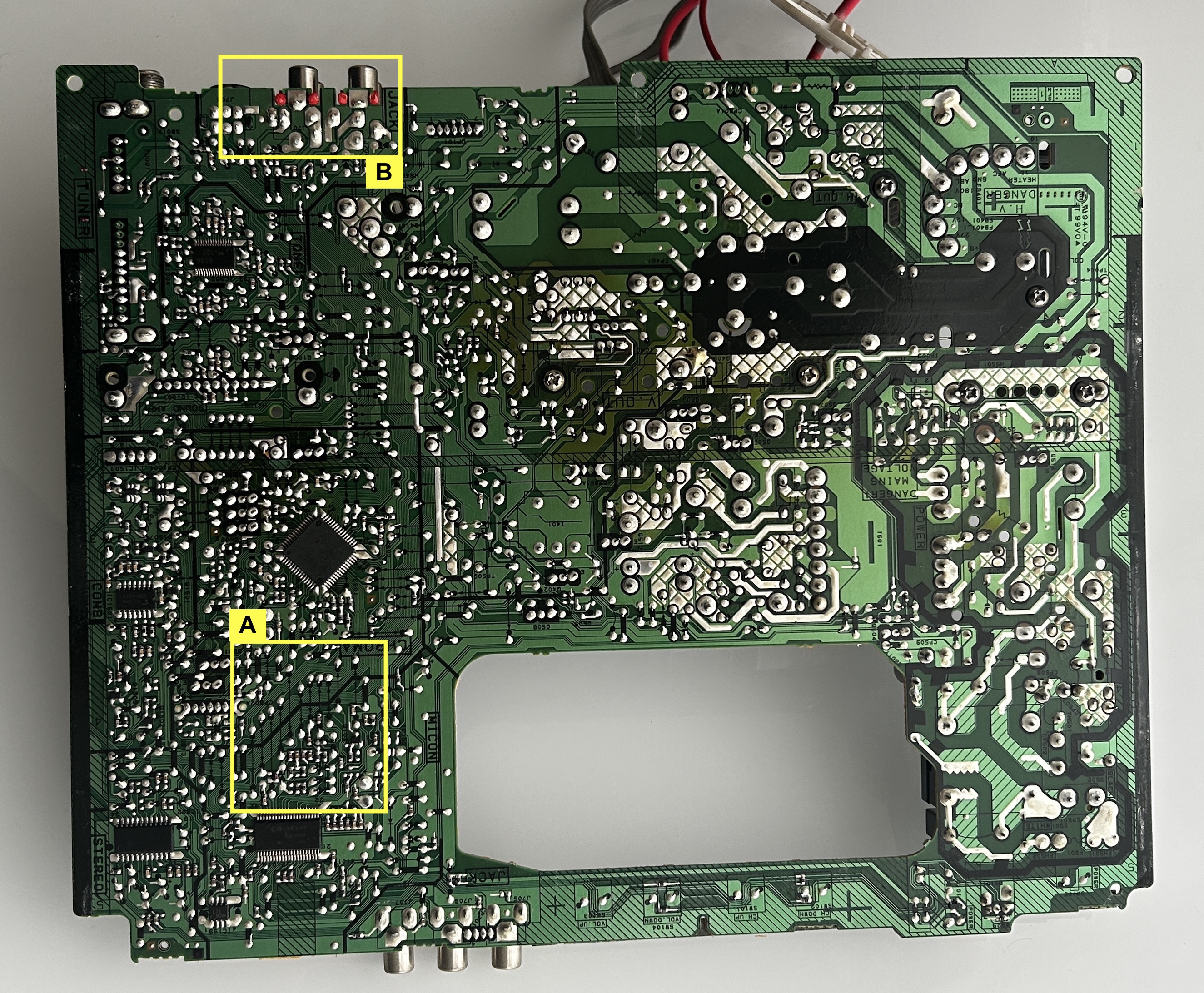
We will be focusing on the following area for the RGB mod.
- Area A is where the RGB and blanking wires will be installed
- Area B is where the audio, sync and groud wires will be installed.
STEP 1: Remove the grounding resistors and capacitors
We are performing an interference supressing mod. Therefore, it is a bit more involved. We are going to remove the three 820Ω RGB ground resistors and the 3 stock 0.1uF capactiors.
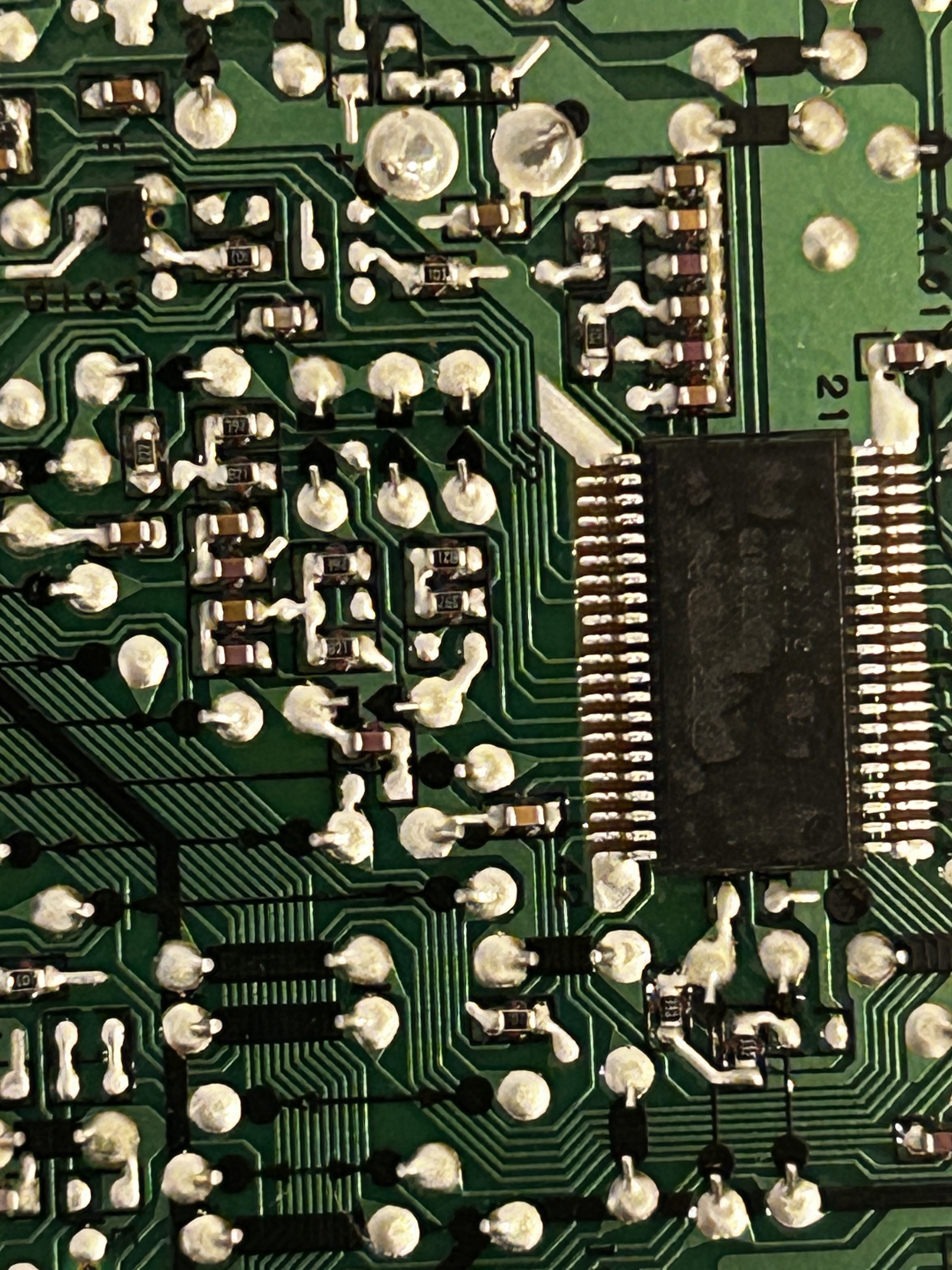
Remove
- R141
- R142
- R143
Remove and short (see pictures)
- C136
- C137
- C138
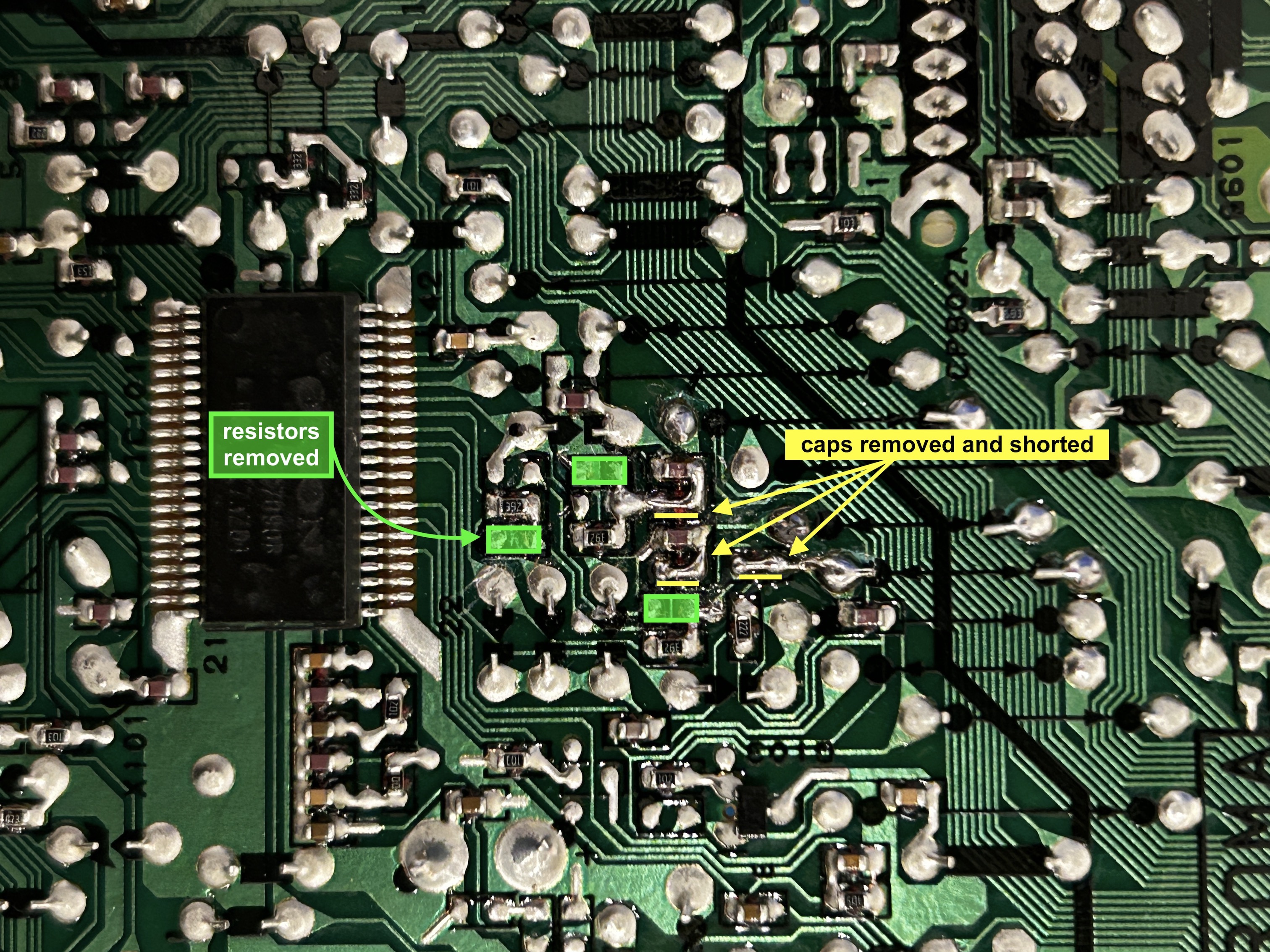
OSD grounding resistors R141, R142, and R143 should be removed. The inline capacitors C136, C137, and C138 should be removed and replaced with small jumpers.
STEP 2: Remove jumpers
Remove the following jumpers. Jumper naming is hard to read on the chassis. Just use the picture as a referene to remove the the jumpers.
- W108
- W110
- W111
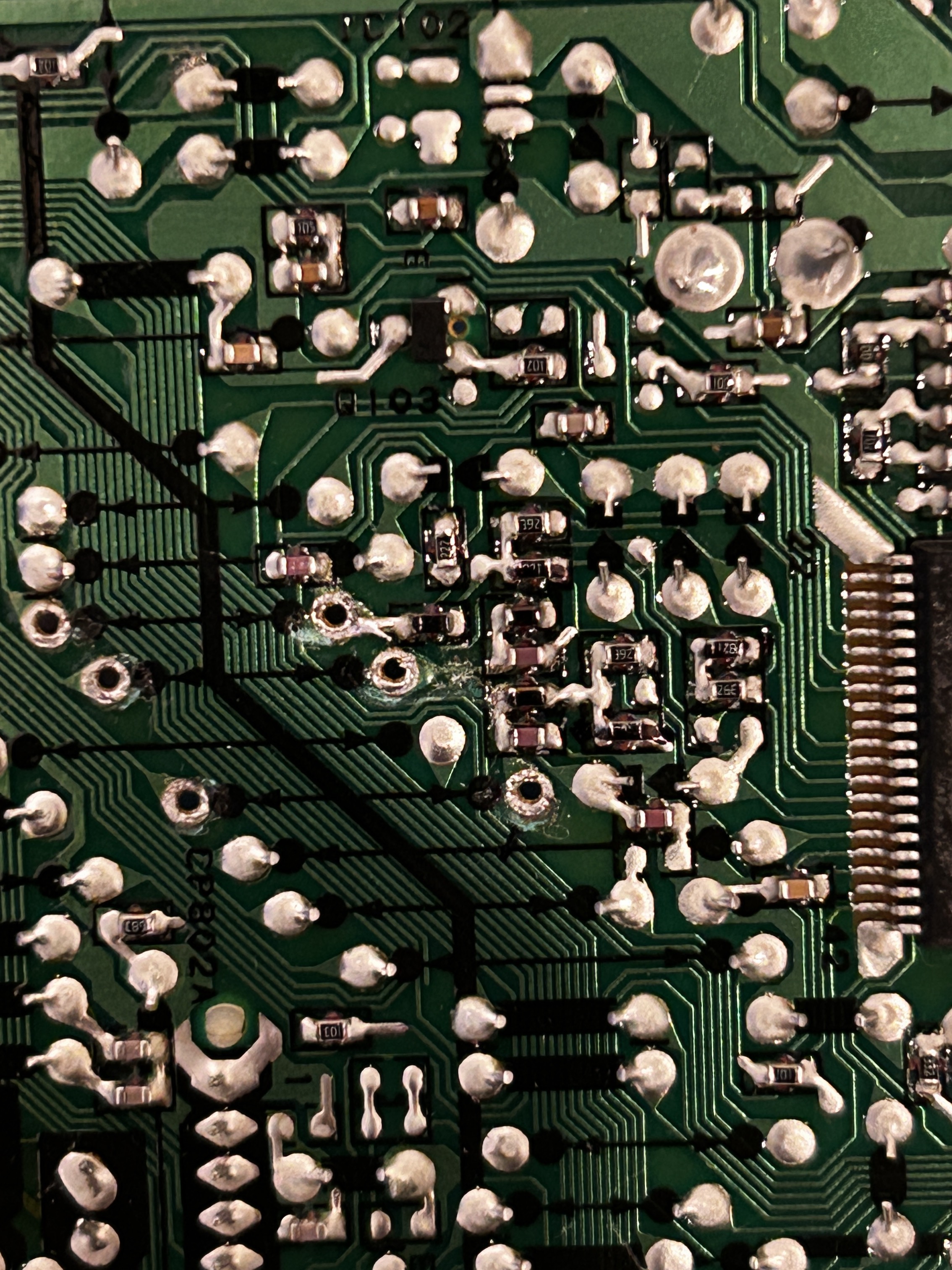
Where we expect the R, G, B and blanking wires to go. Don't remove jumper W052.
![]()
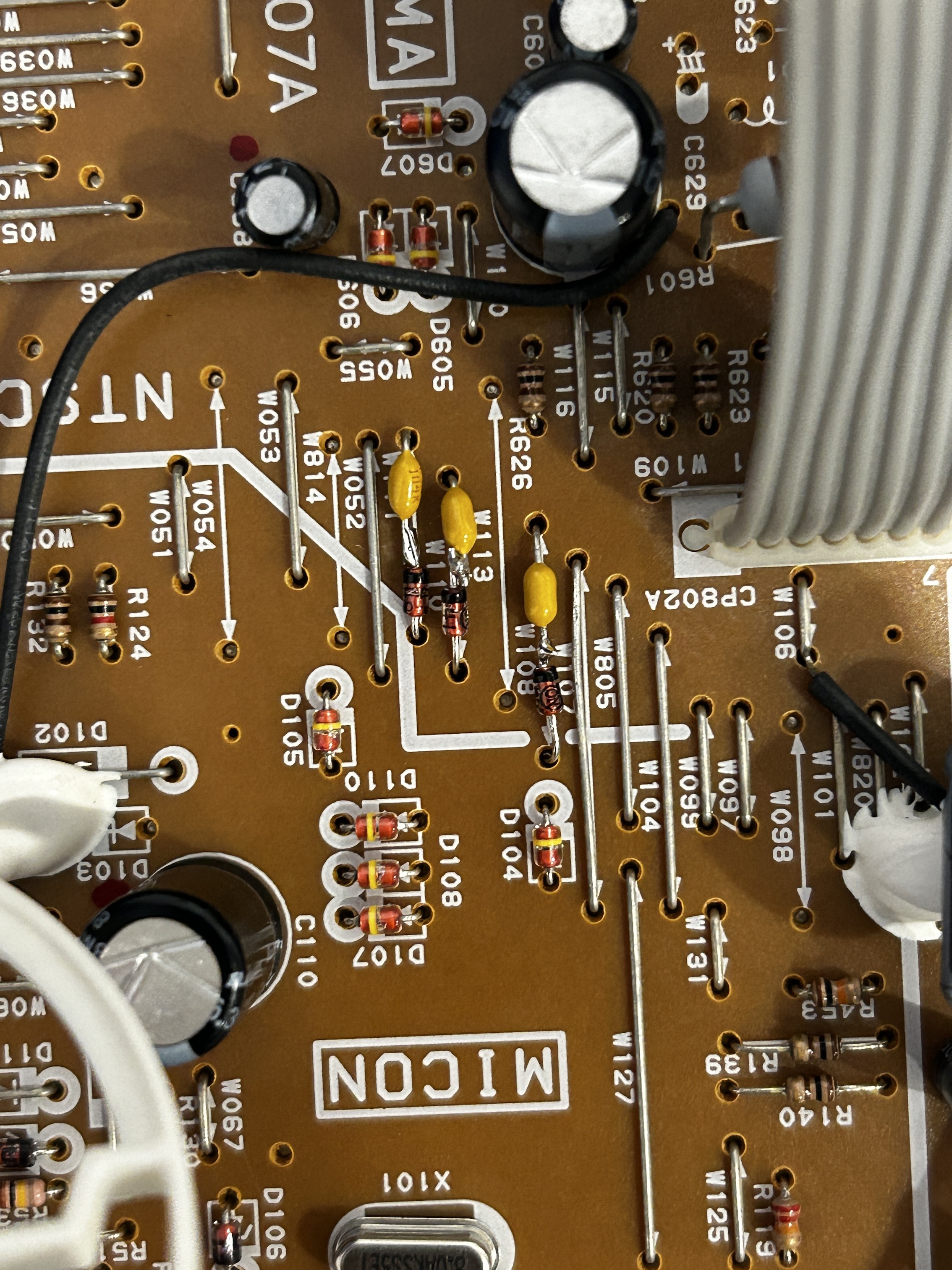
STEP 3: Replace jumpers with capacitors and diodes
Warning
Diode direction and capacitor placement matters. Follow the direction carefully.
Replace the removed jumpers with 1N4148 diodes and 0.1uF ceramic capacitors, ensuring they are installed in the correct orientation. Pay close attention to the direction of the diodes, as placing them incorrectly will prevent the modification from working. The stripe on the diode must face the right direction.
Picture below illustrates the direction of these components as well as where the RGB lines should be connected. Pay attention to the direction of the diodes. The blanking wire (brown) should be connected to jumper W052.
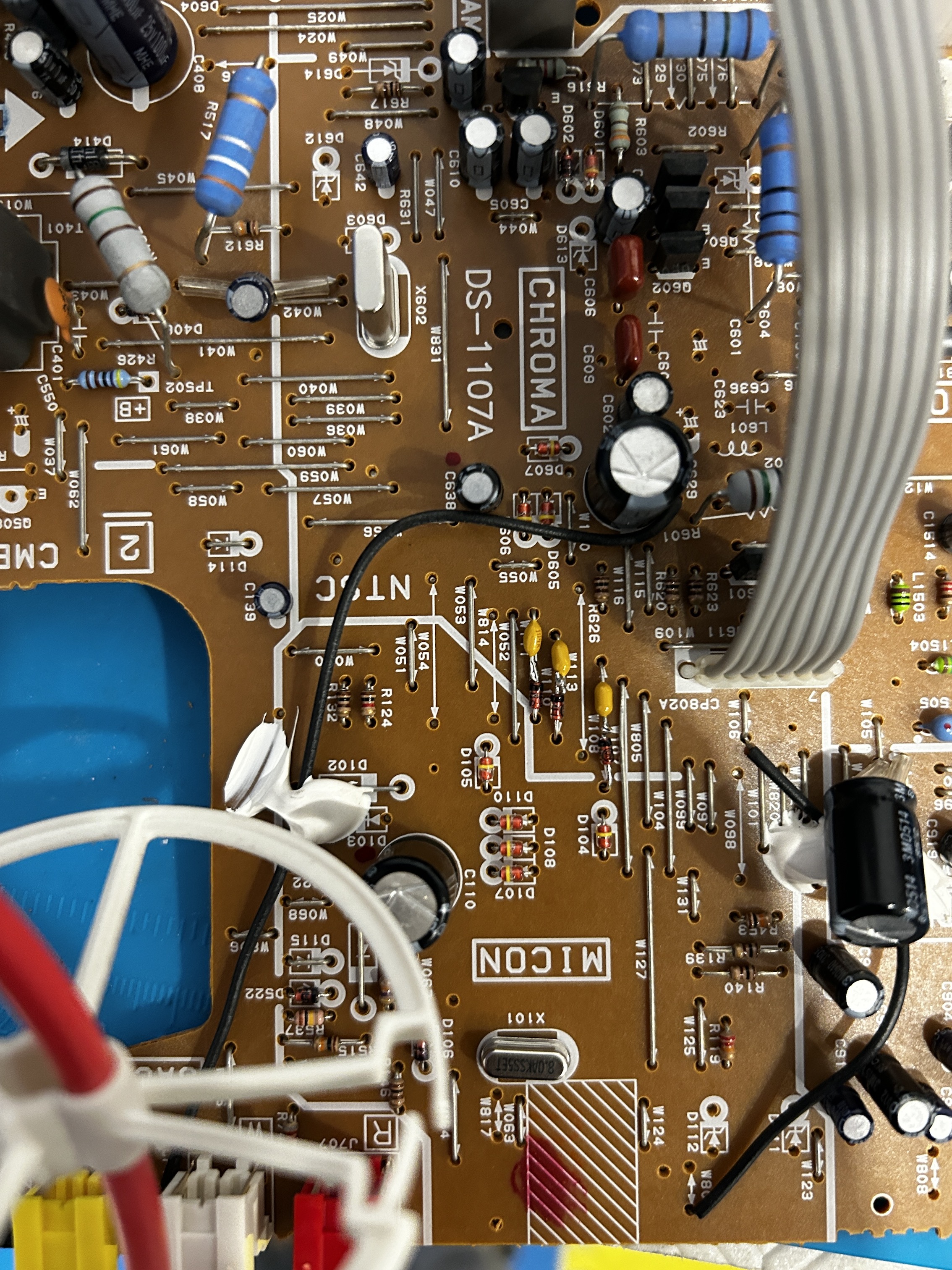
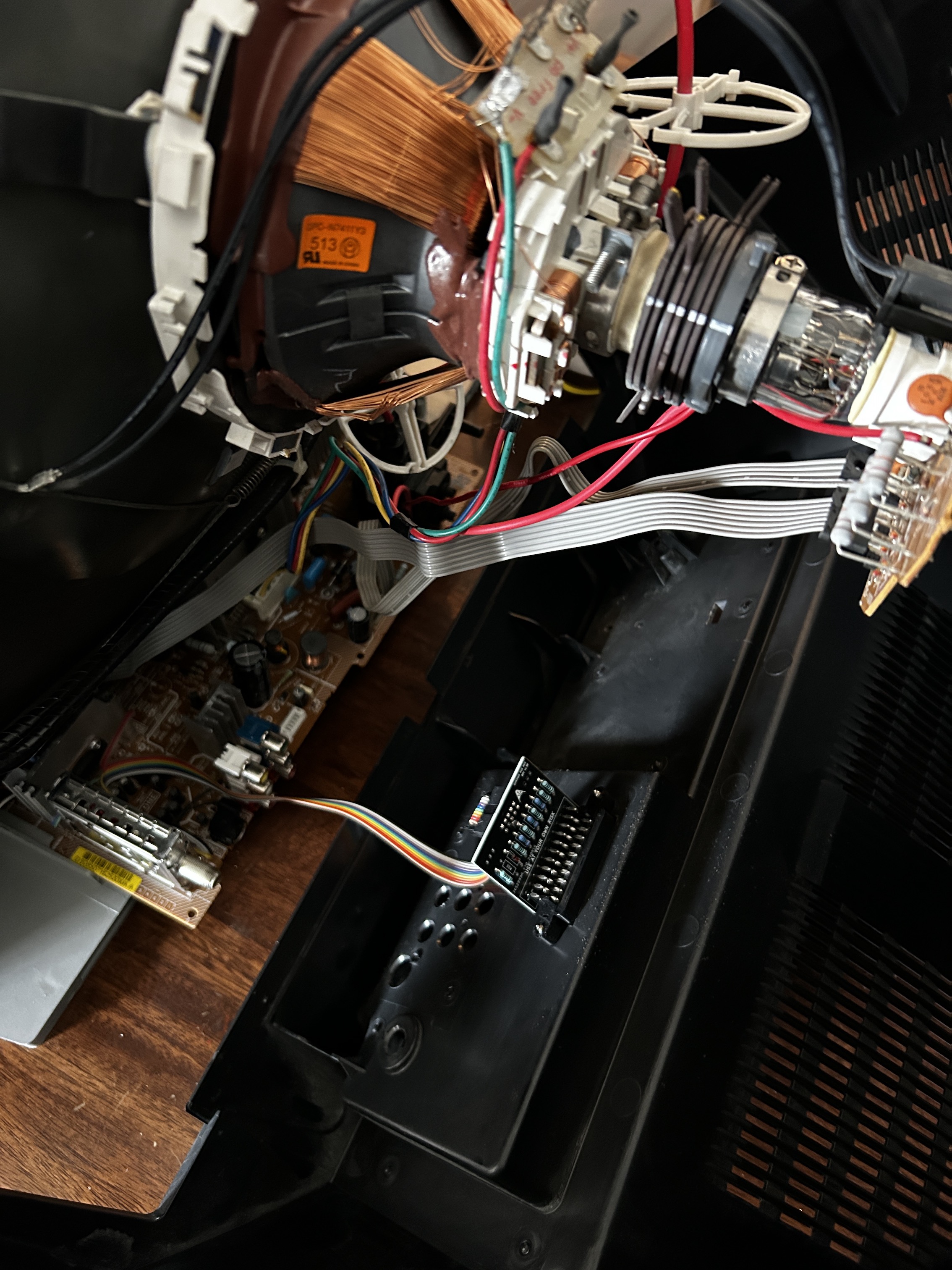
STEP 4: Connect RGB and blanking wires
Make sure the wires are installed in-between the diodes and capacitors similar to the picture below.
![]()
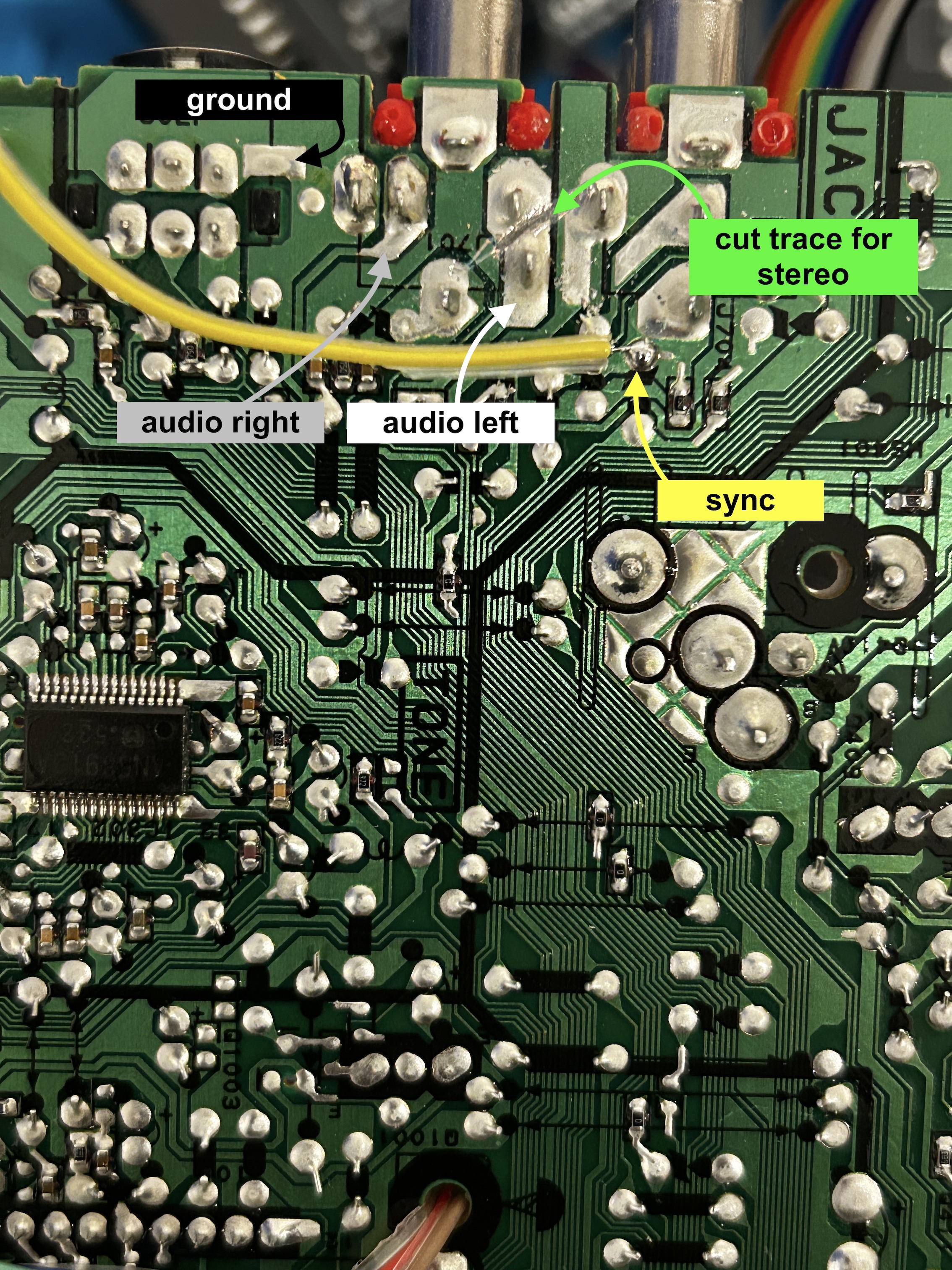
STEP 5: Connect sync, ground, and audio
Inject the sync signal into the Component Luma (Y) input, and connect the audio to its corresponding audio lines. Refer to the attached photo for the correct connection points. Additionally, cut the trace as indicated to permanently enable stereo audio and avoid the use of dummy plug. If you do not cut this trace, you'll need to have something plugged into the red RCA audio port (right audio) for stereo to function.
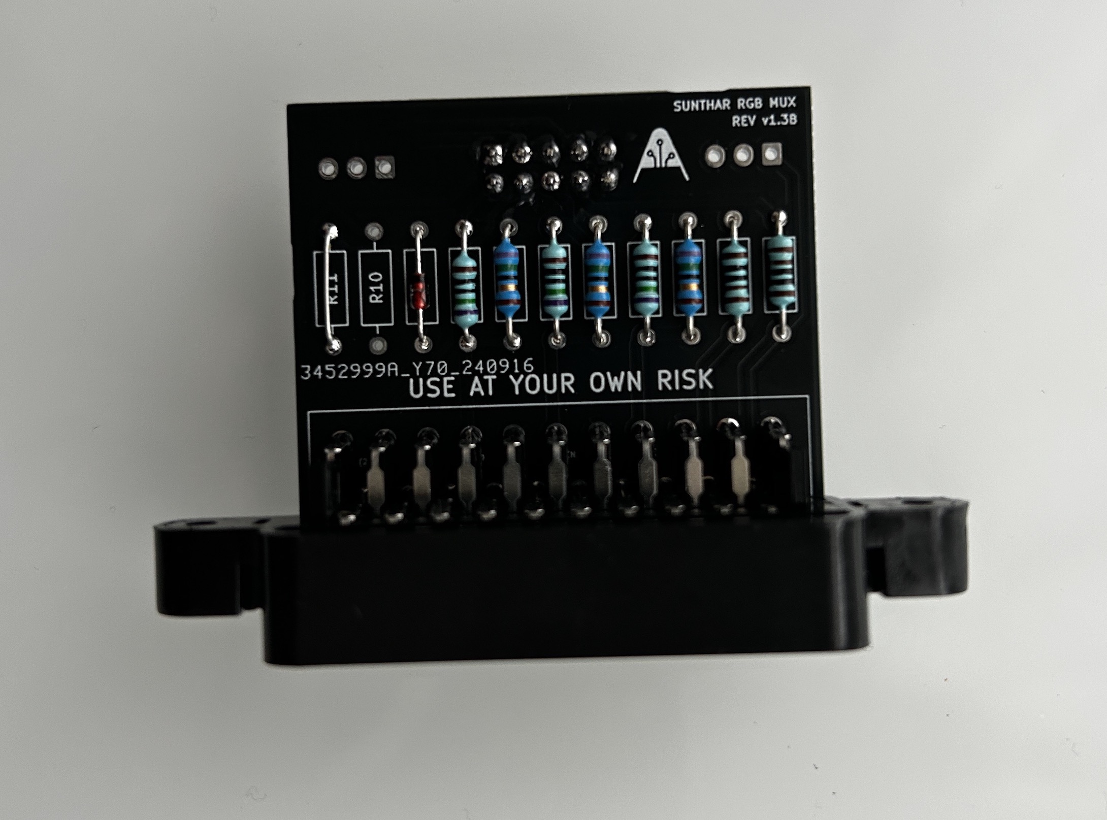
STEP 6: Build your mux circuit
This mod uses the RGB mux board. This is optional, but will make your mod easier and stable. You can also create the circuit presented in the schematics above without the board. Please also checkout the mux calculator to play with your own values.
| On Toshiba CRT Chassis | 27A35 |
|---|---|
| CRT RGB inline resistor | 3.9kΩ |
| CRT RGB ground resistors removed | 820Ω |
| 0.1μF caps replaced | Yes |
| Add diodes on chassis RGB lines? | Yes |
| Add blanking diode on chassis | No |
| RGB mux board | 27A35 |
|---|---|
| Mux board RGB termination (R1, R2, R3) | 75Ω |
| Mux board RGB inline resistors (R4, R5, R6) | 750Ω |
| Mux board Audio LR (R7, R8) | 1kΩ |
| Mux board blanking diode (R9) | 1N4148 |
| Mux board blanking ground resistor (R10) | open |
| Mux board blanking resistor (R11) | short |
Compatible mux boards:
Warning
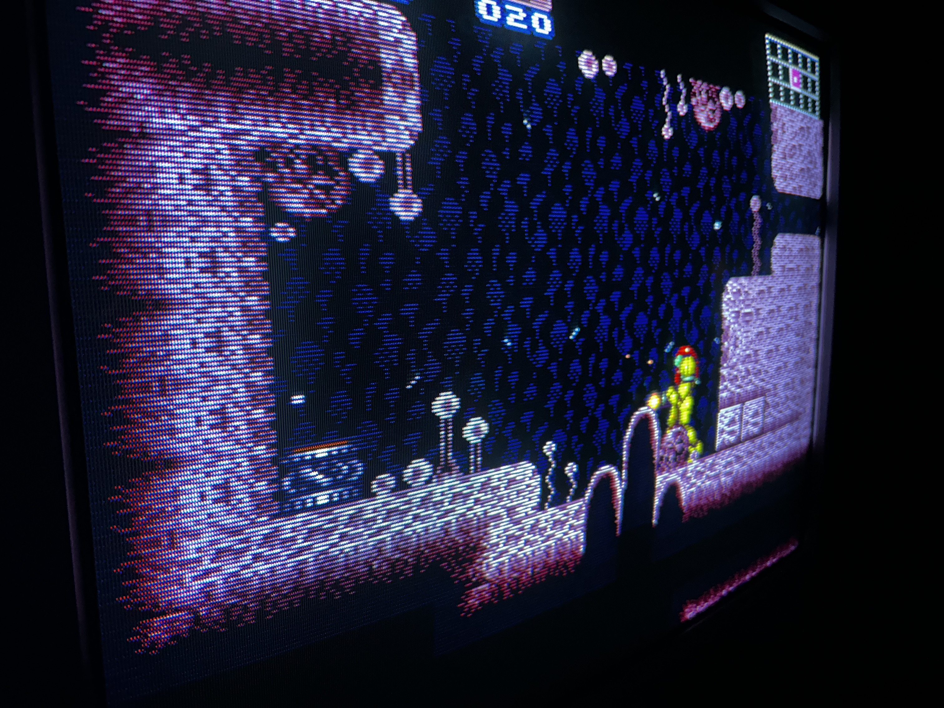
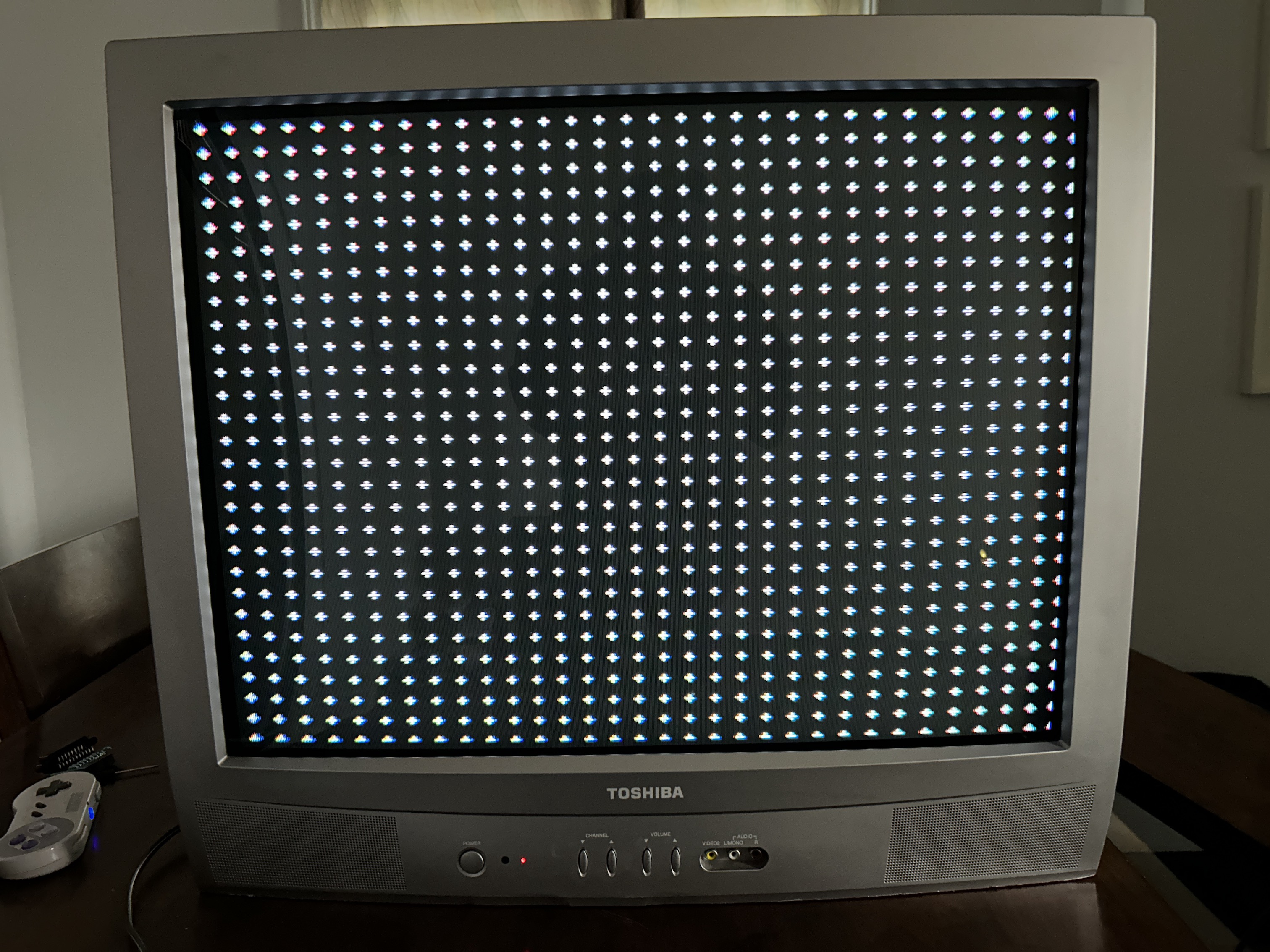
I'm often asked why a black and white image appears after an RGB mod. This issue occurs due to insufficient blanking voltage, which prevents the RGB chroma input from being enabled. What you're seeing in this case is the sync signal being sent to the luma input. To fix this, short R11 and leave the diode on R9. See the mux configuration above. Never exceed 5V with blanking - you will fry the chroma IC.
![]()
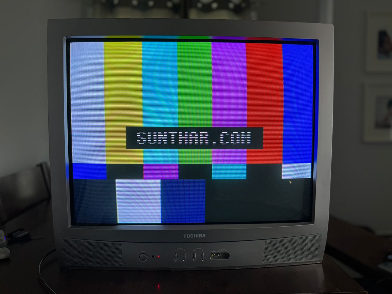
In the above image R9 had the diode and R11 had 1 kΩ resistor. I was able to test this with the RGB tuner.
STEP 7: Attach the female SCART connector to TV
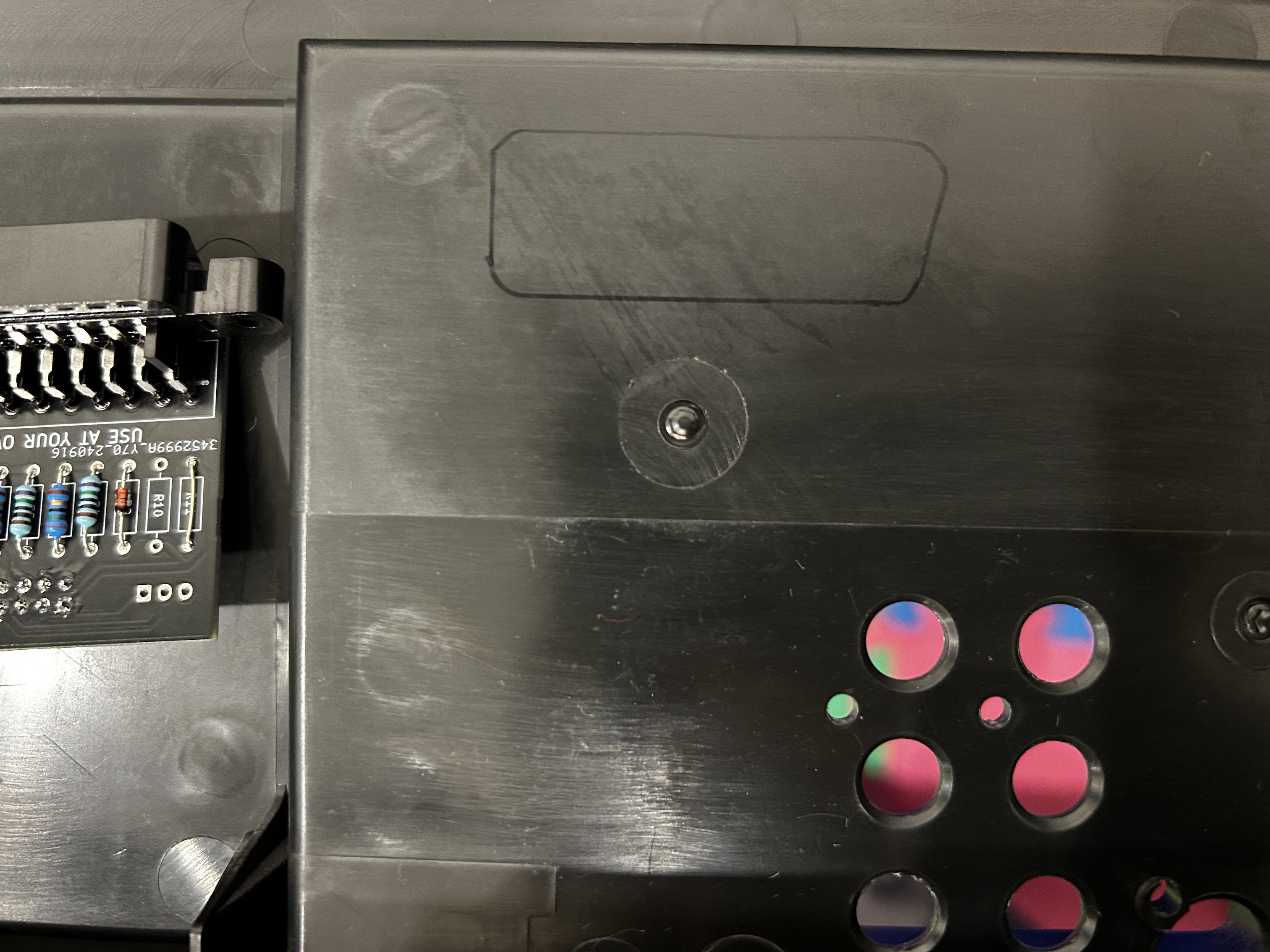
Creating a SCART cutout and mounting it is an art. I have a dedicated section for it. How to create and mount a SCART female plug?
Muxed OSD over RGB
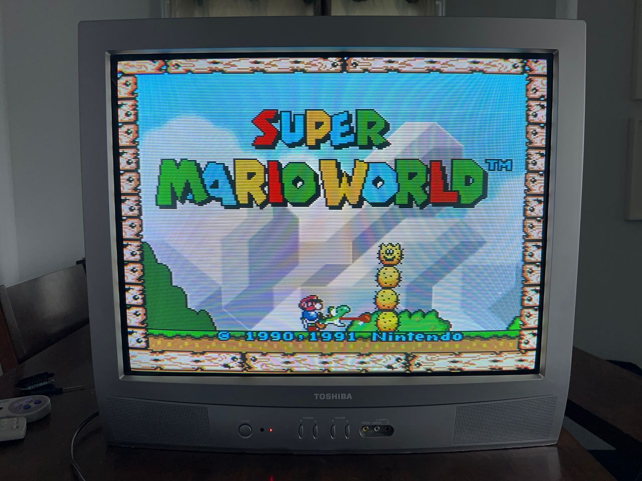
Games

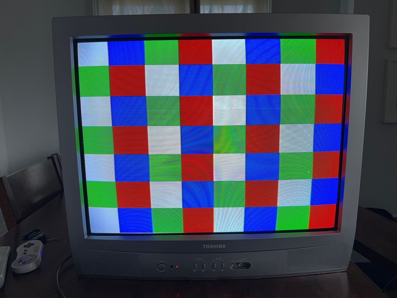
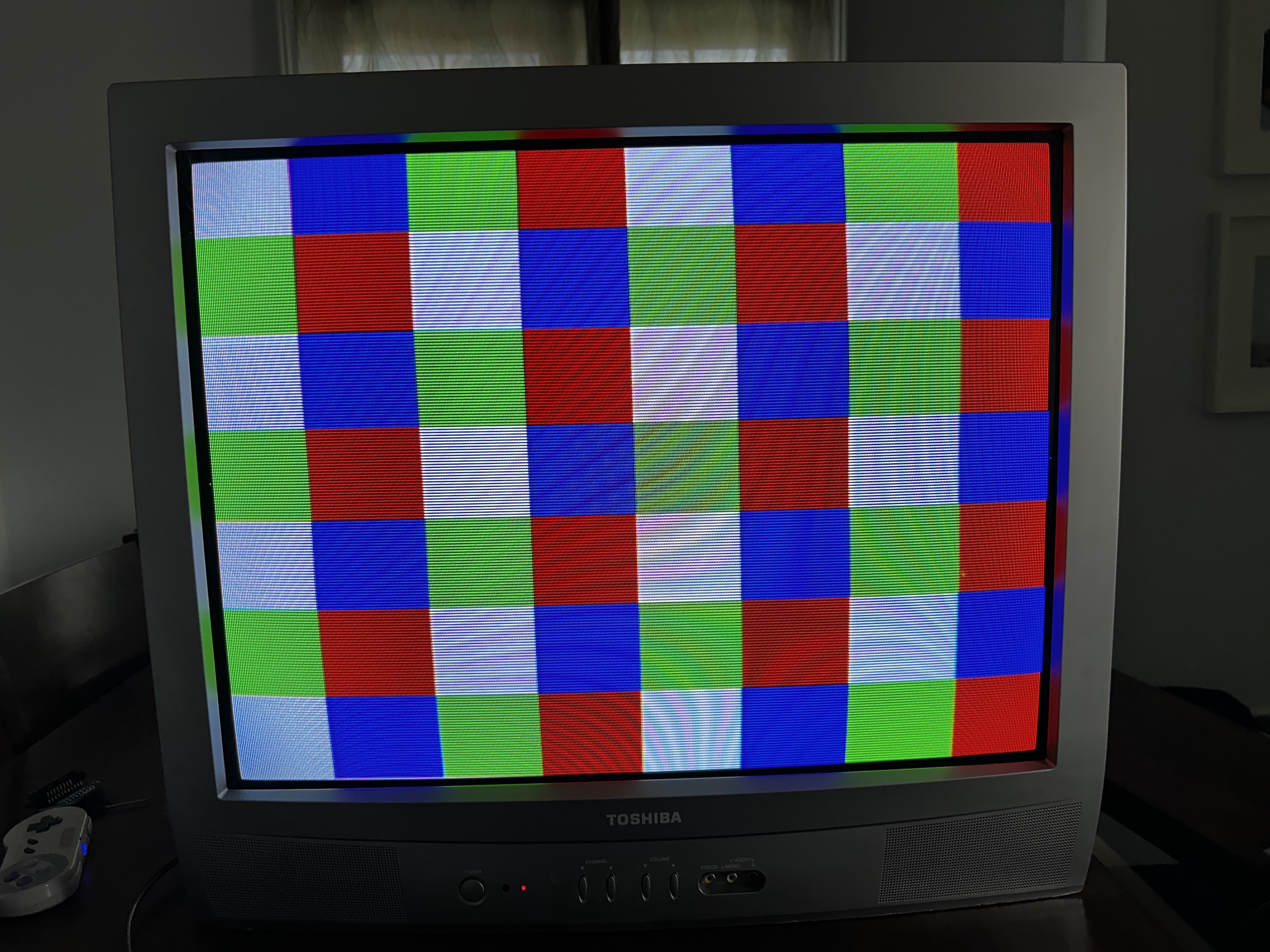
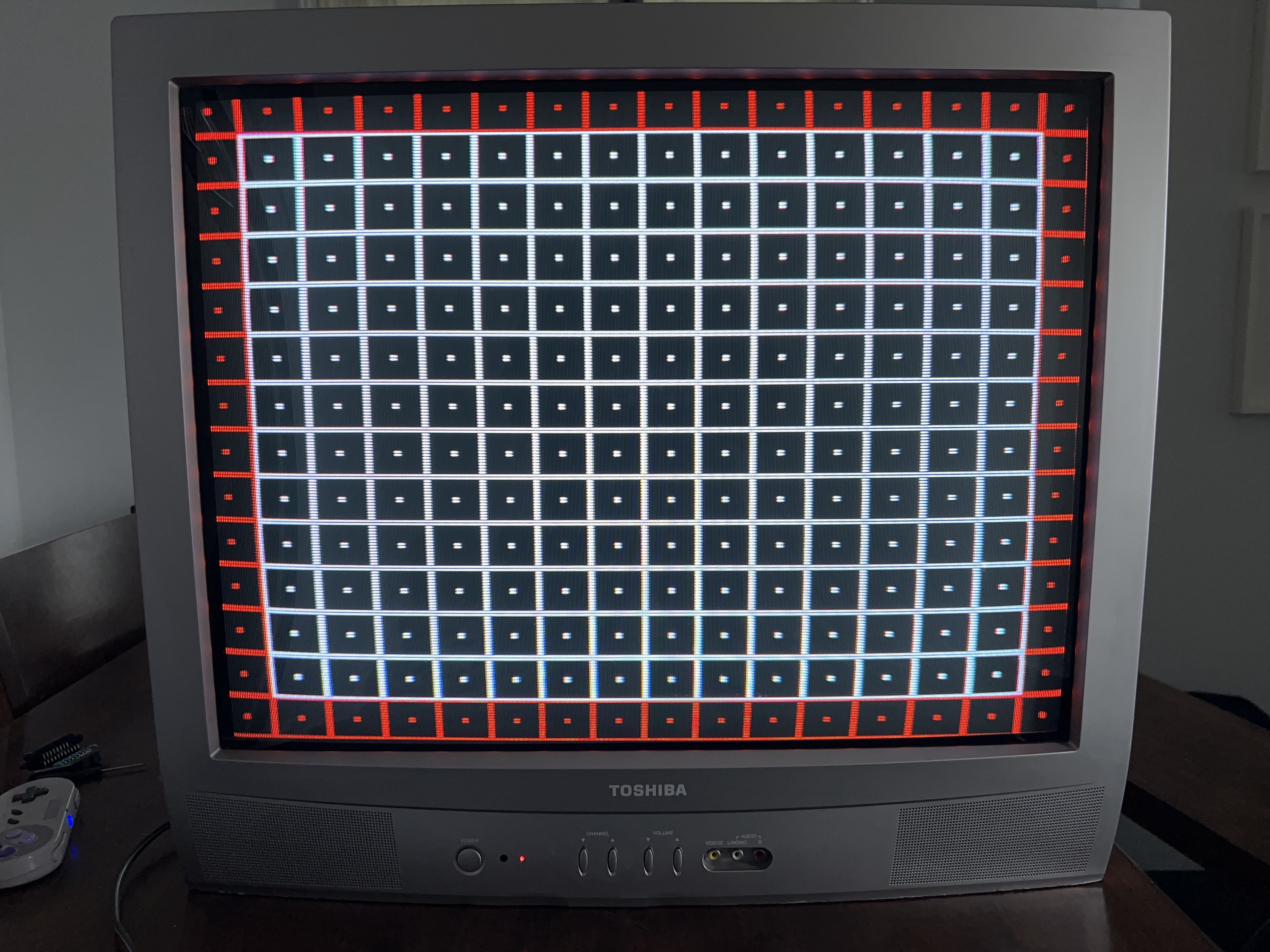
Patterns
Set
Back open 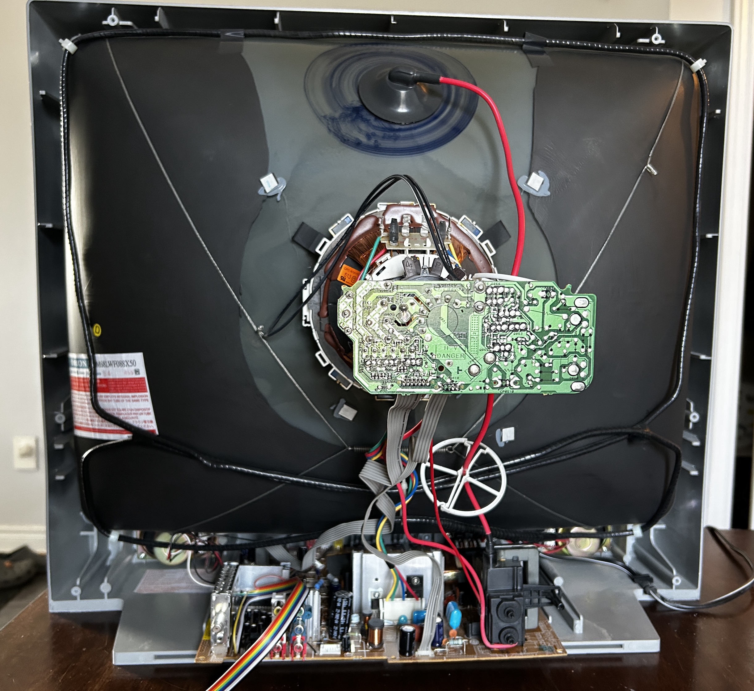
Flyback 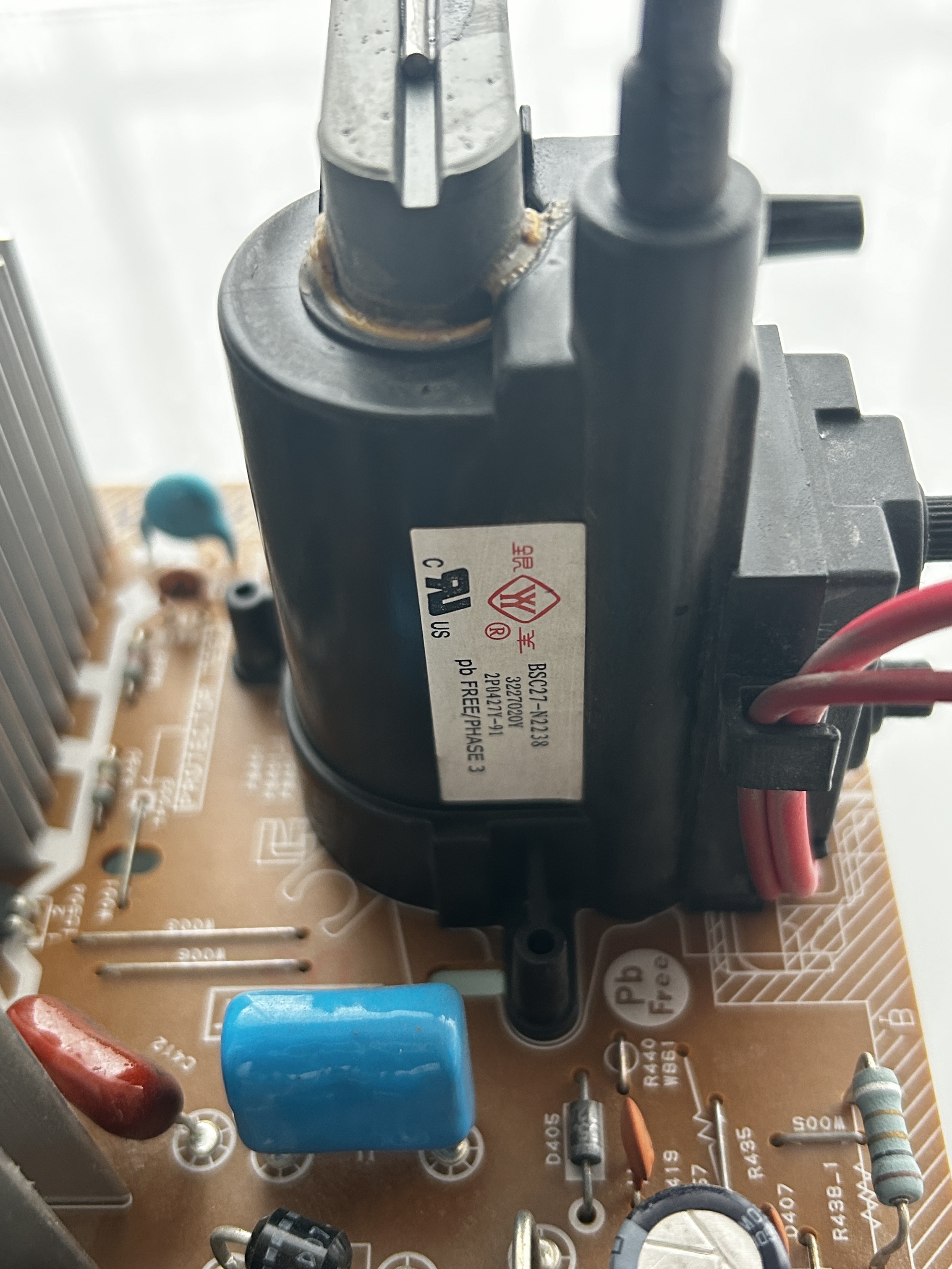
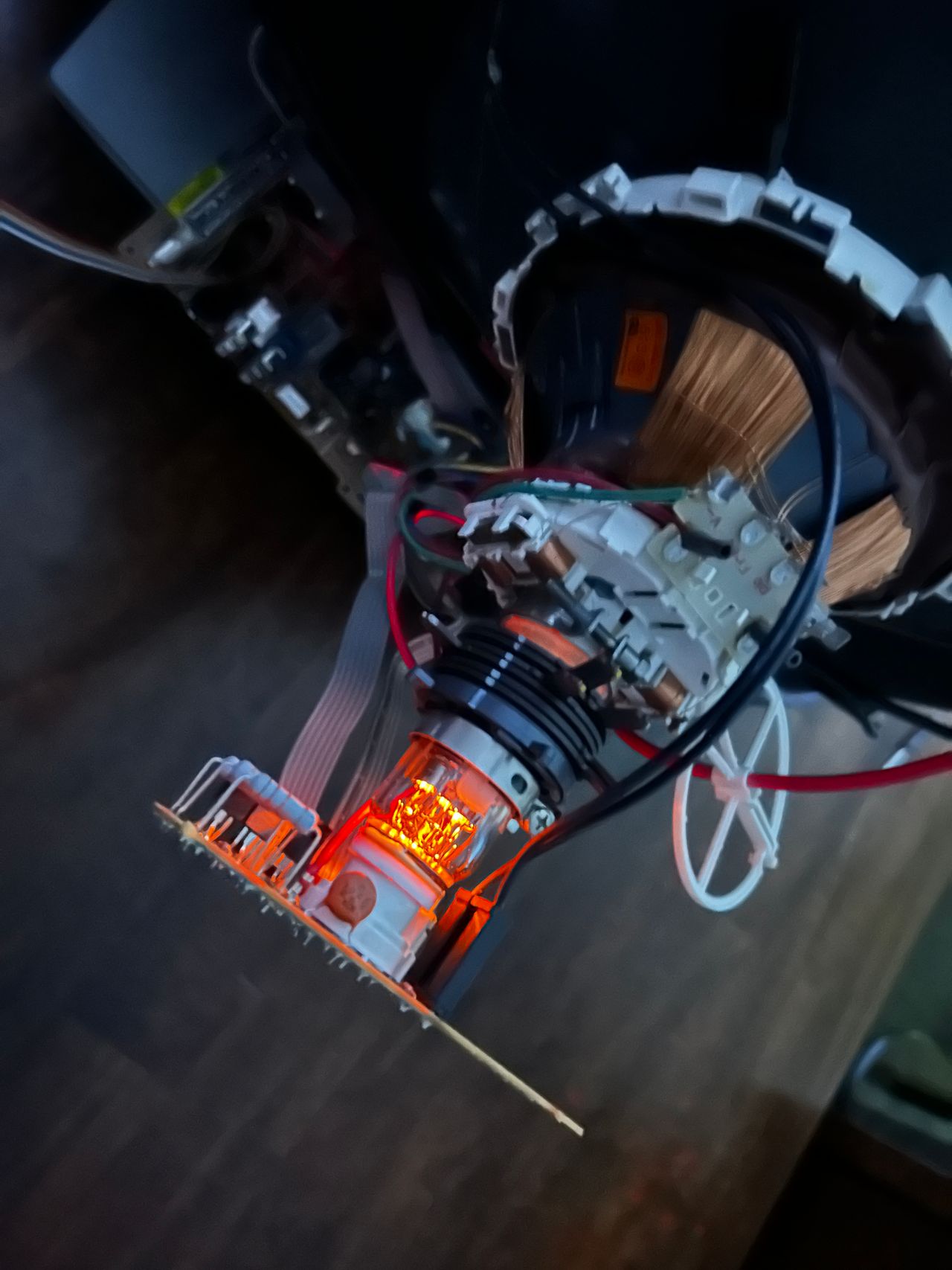
Cathode Glow 
Neck board 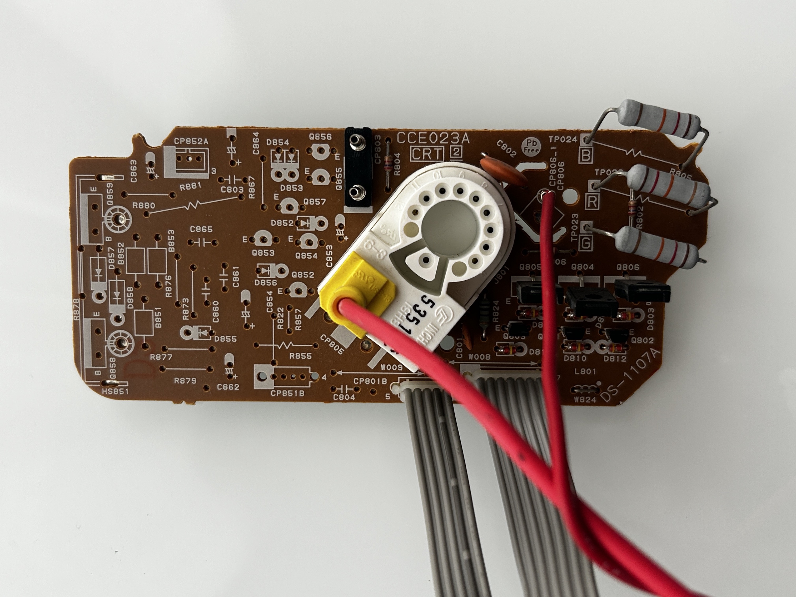
Speaker 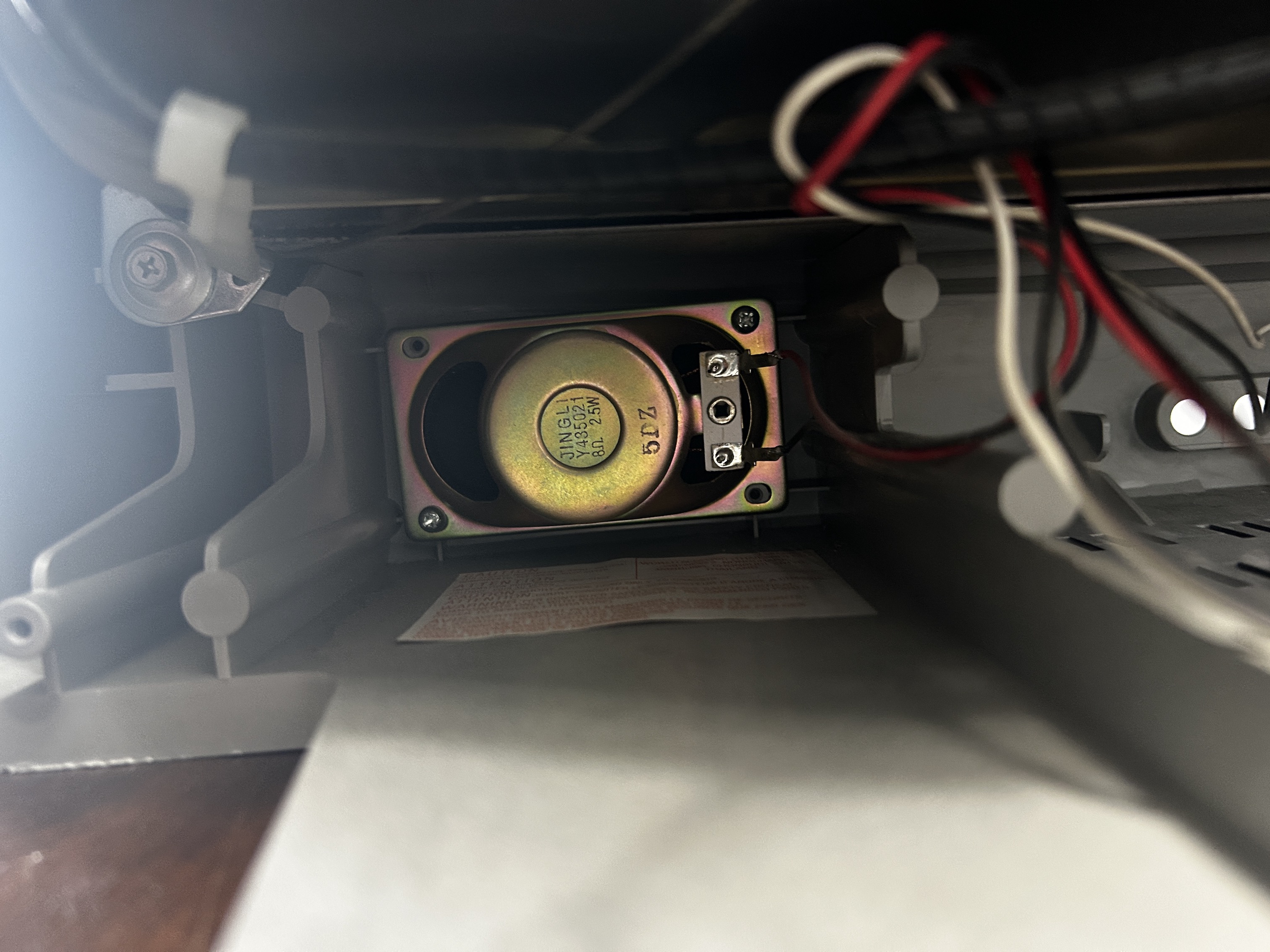
Tuner 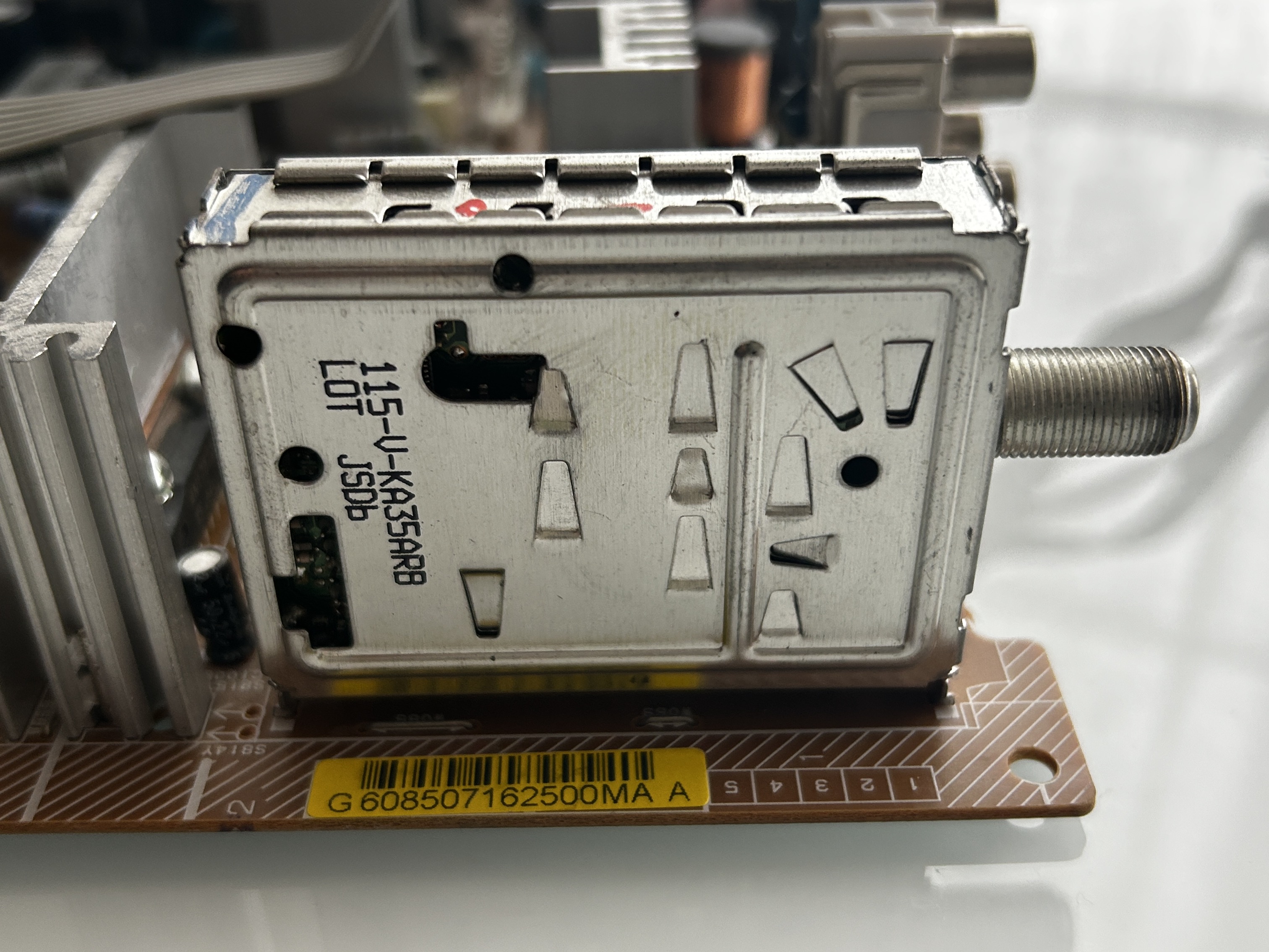
Anode cap 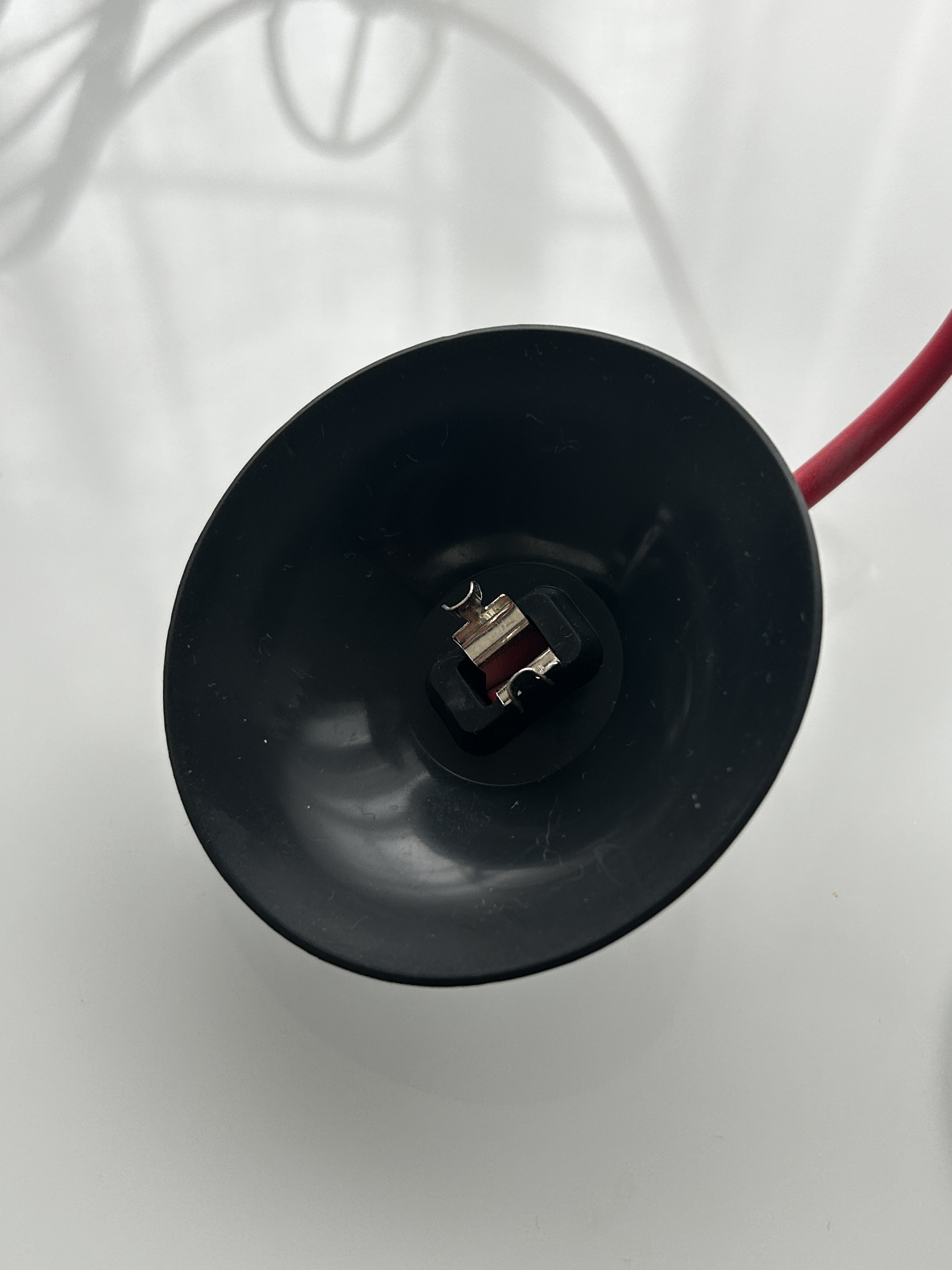
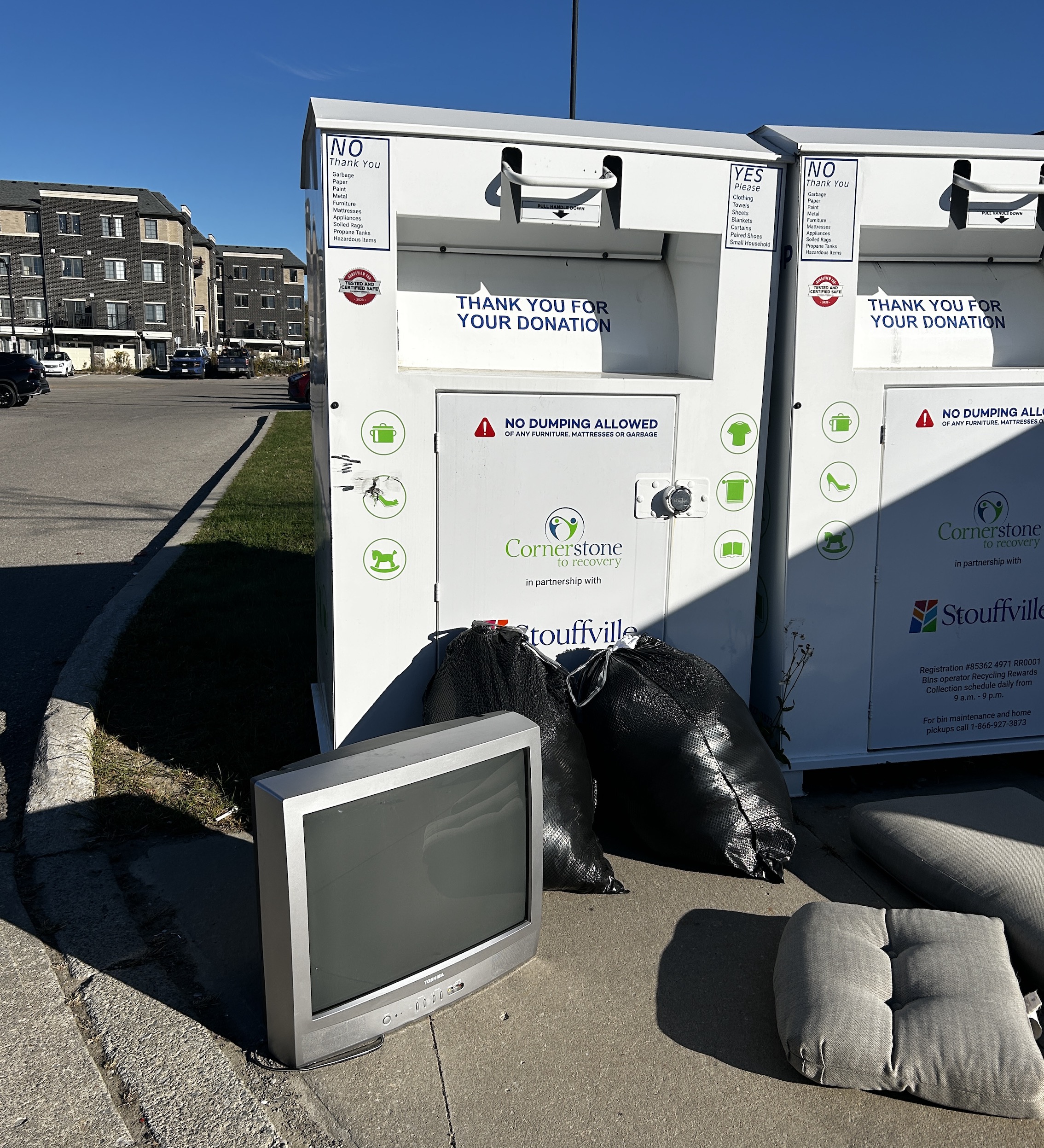
Where this set was found?
Pictures
Reference Photos