JVC C-13110
JVC C-13110 CRT RGB mod
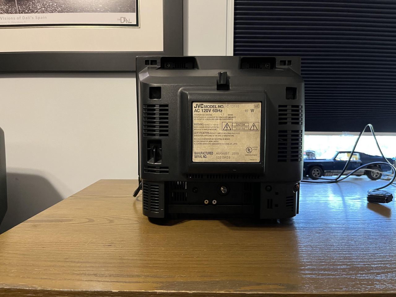
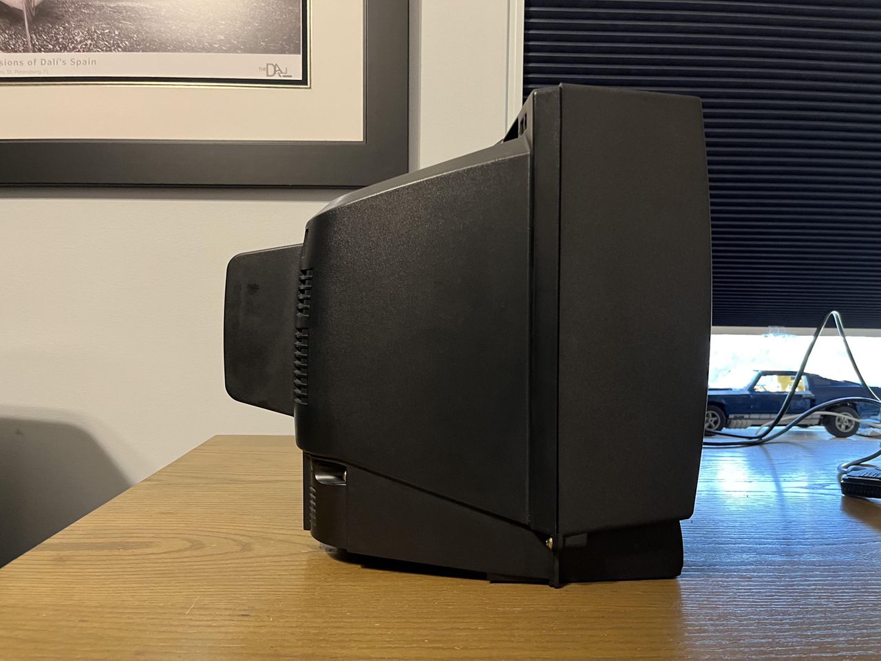
The JVC C-13110 is a 13" CRT color television from the late 1990s designed for consumer use. It delivers a sharp picture and is a perfect candidate for RGB modification.

View full CRT details and more mod examples →
This tutorial covers the RGB mod for JVC C-13110. Looking through the service manuals these instructions should also work for other JVC models (AV-13810 / AV-20810 etc.)
Contributors
Thank you to everyone who contributed to this guide:
- John Figueroa — author, RGB mod and pictures
CRT safety
Caution
You can die doing this! So read carefully! CRT TV is not a toy. Do not open a CRT TV. If you don't have any prior knowledge about handling high voltage devices, this guide is not for you. CRT TV contains high enough voltage (20,000+ V) and current to be deadly, even when it is turned off.
Plan of attack
Theory
Sometimes it is nice to know the theory behind the mod. I have put this on a separate page. This shows how the various resistor values are calculated.
Manuals and Datasheets
- JVC C-13110 Service Manual
- Toshiba TA1242N Datasheet (Jungle)
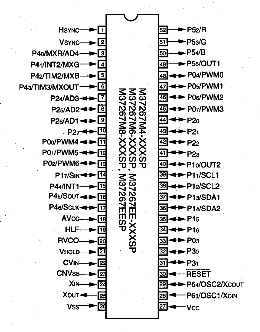
- Mitsubishi M37272MAH-501SP Datasheet (OSD)
Specs
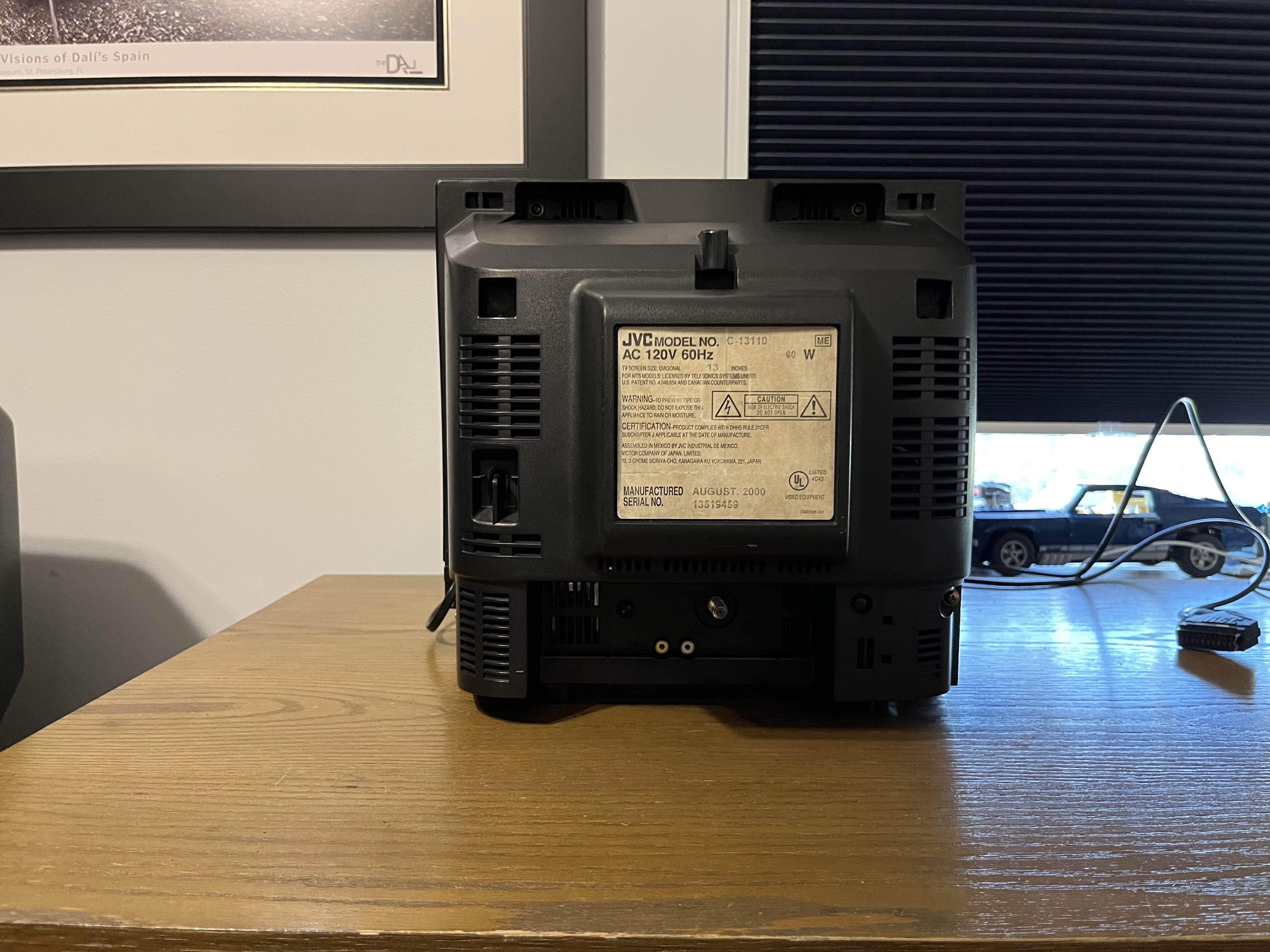
- Manufactured: Mexico (2000)
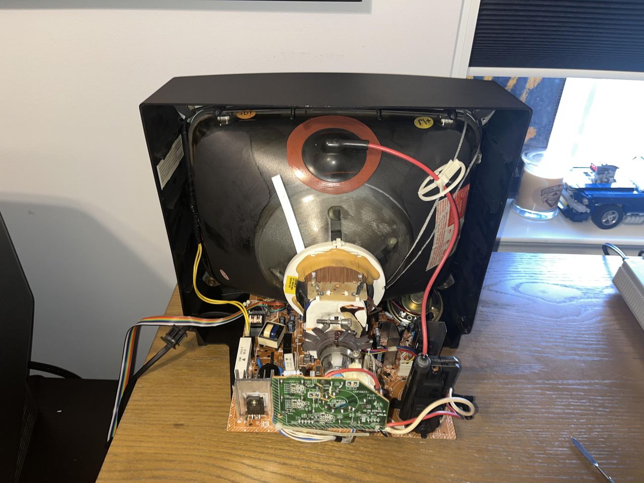
- Chassis: FV5
- Tube: JVC A34KQW42X
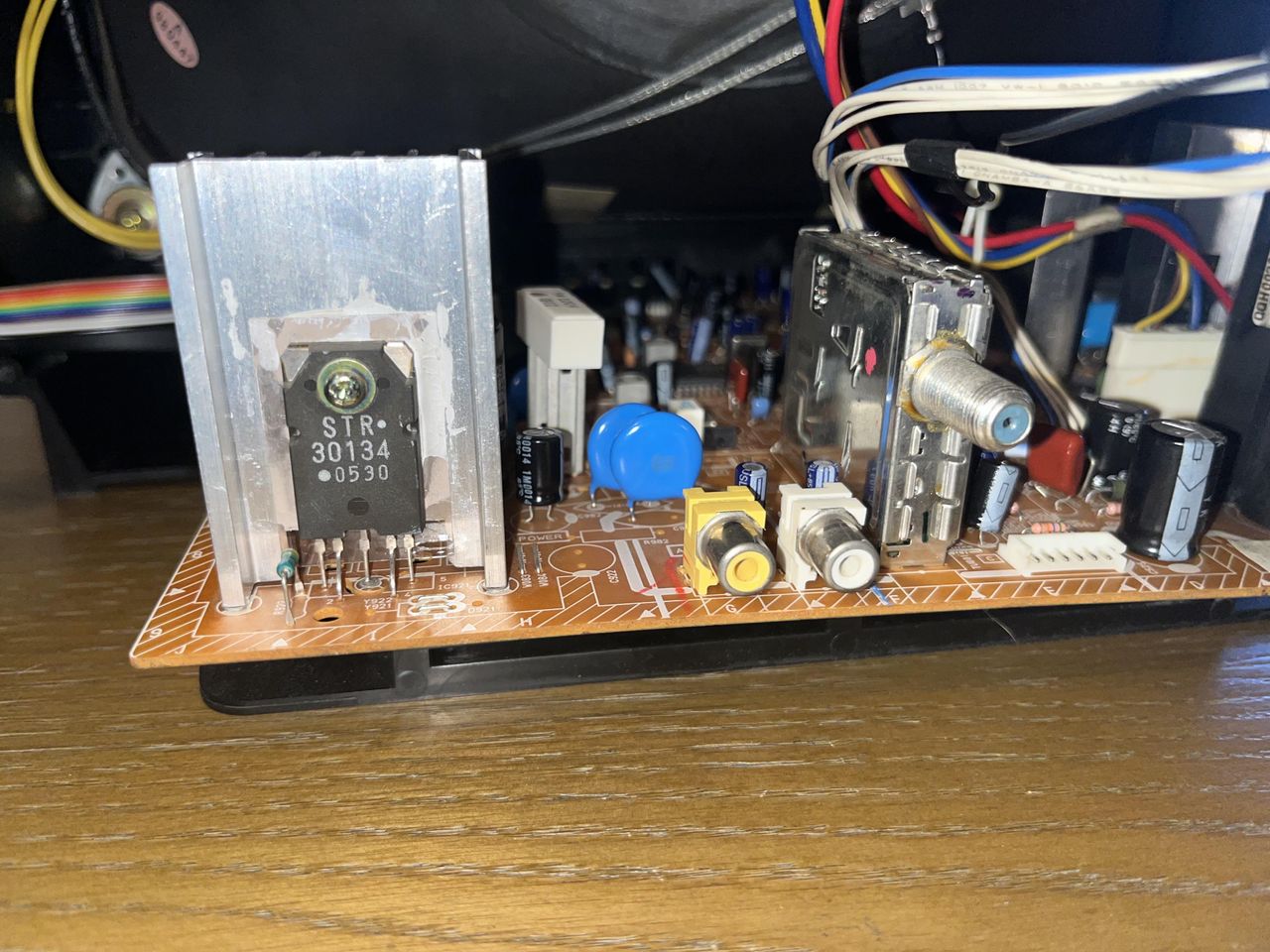
- Jungle Chip: Toshiba TA1242N
- OSD Chip: Mitsubishi M37272MAH-501SP
- Screen Size: 13"
RGB mux diagram
Prepare the mux diagram. If you are building your own circuit, this diagram should help.
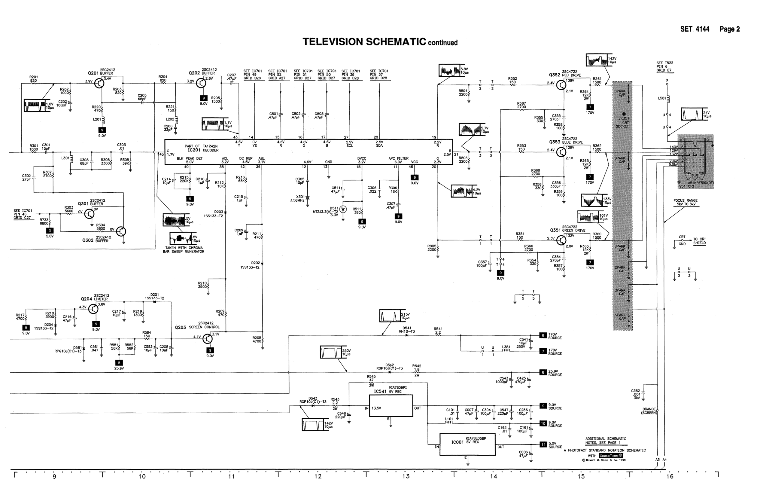
Schematics
Followed the specs from JVC C-20810. The jungle chip used in C-13110 was the same. Resistor values might be different. Measure what's on your chassis.
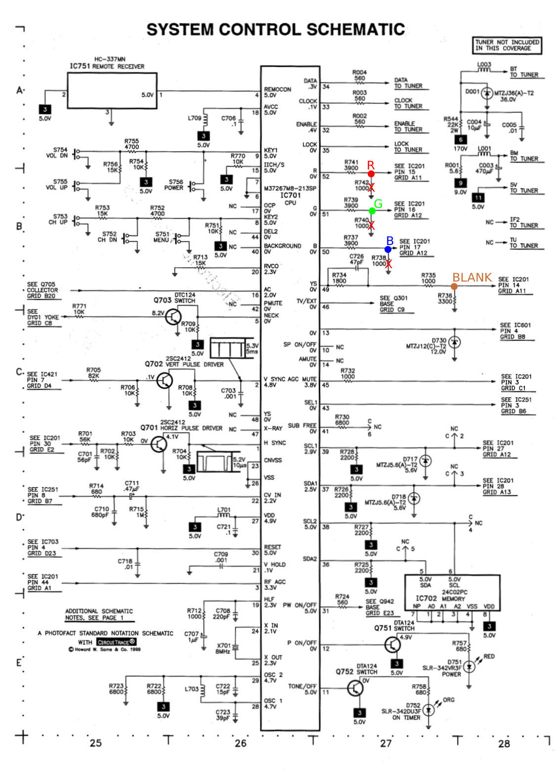
Calculating the RGB external resistor value
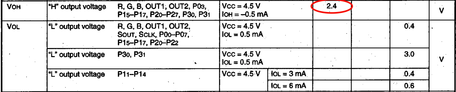
From the M37267M4 (OSD) chip datasheet we know the RGB high voltage is 2.4V.
Let's now calculate the peak-to-peak voltage on the RGB lines that is sent to the chroma chip.

Now that we know the expected peak-to-peak voltage by TA1242N (chroma) chip is 0.5V, let's calculate the RGB resistor value needed.

0.5 x (3900 + 75) - (75 x 2.4) / (2.4 - 0.5) = (1987.5 - 180) / 1.9 = 950Ω
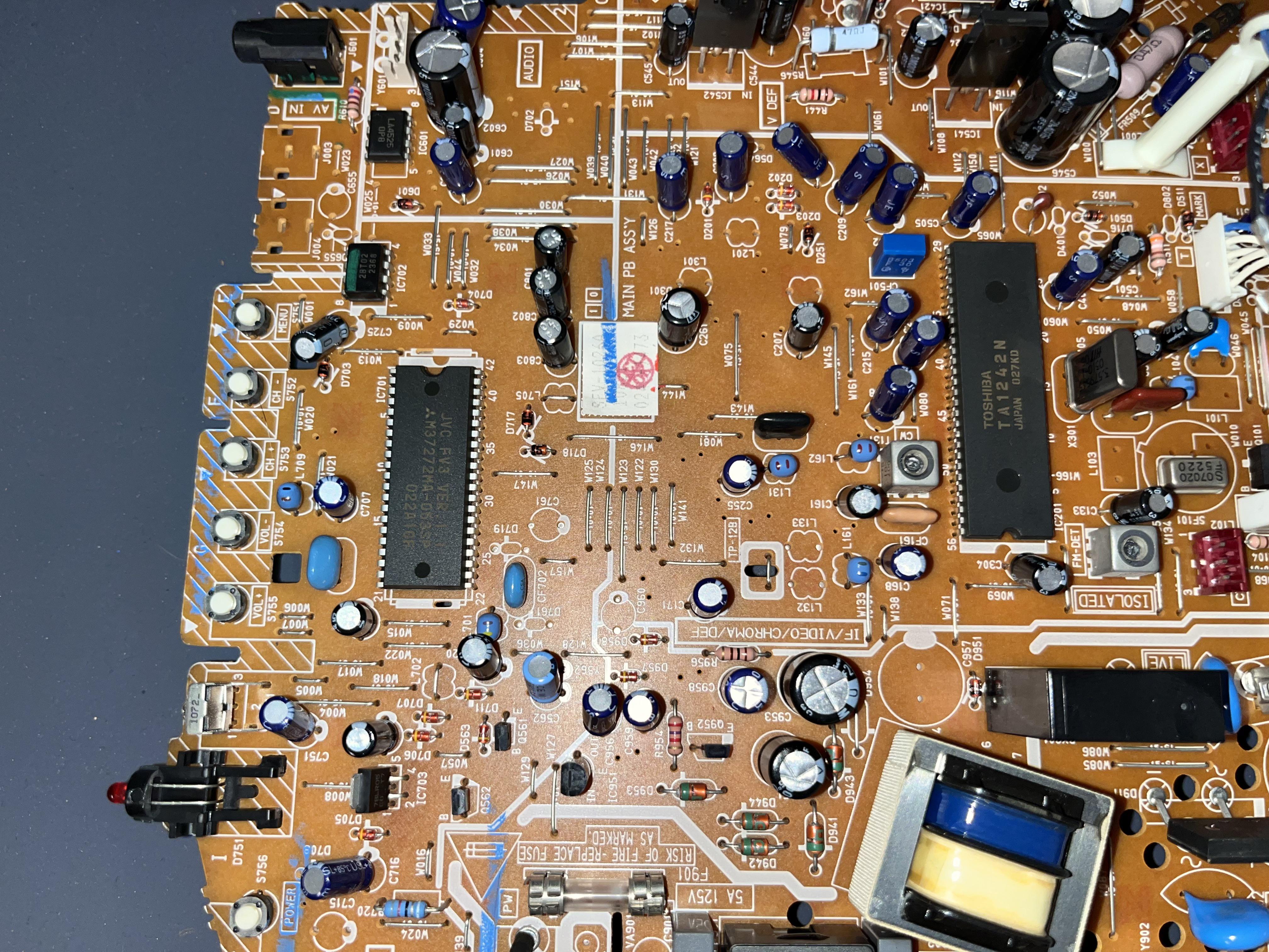
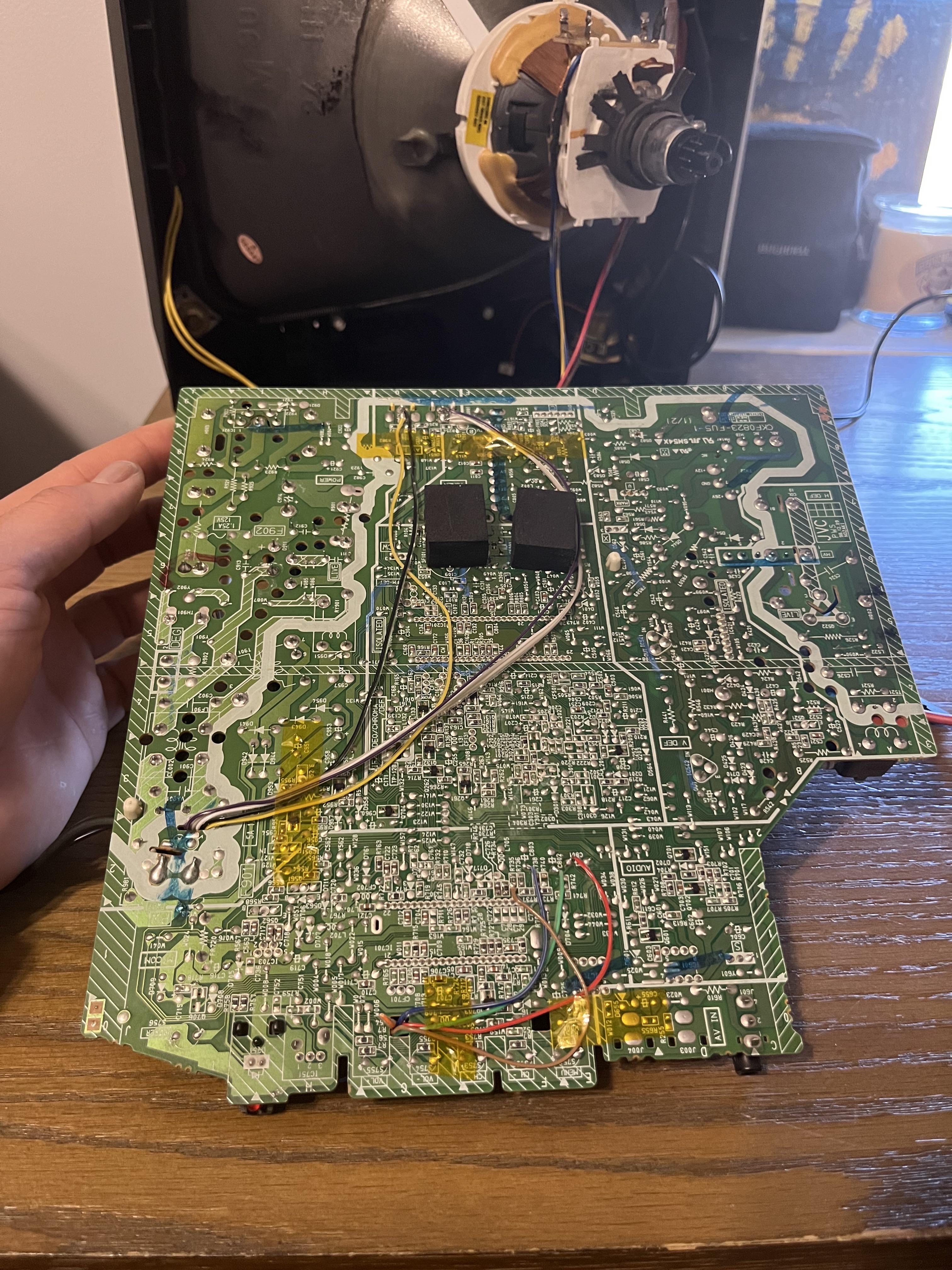
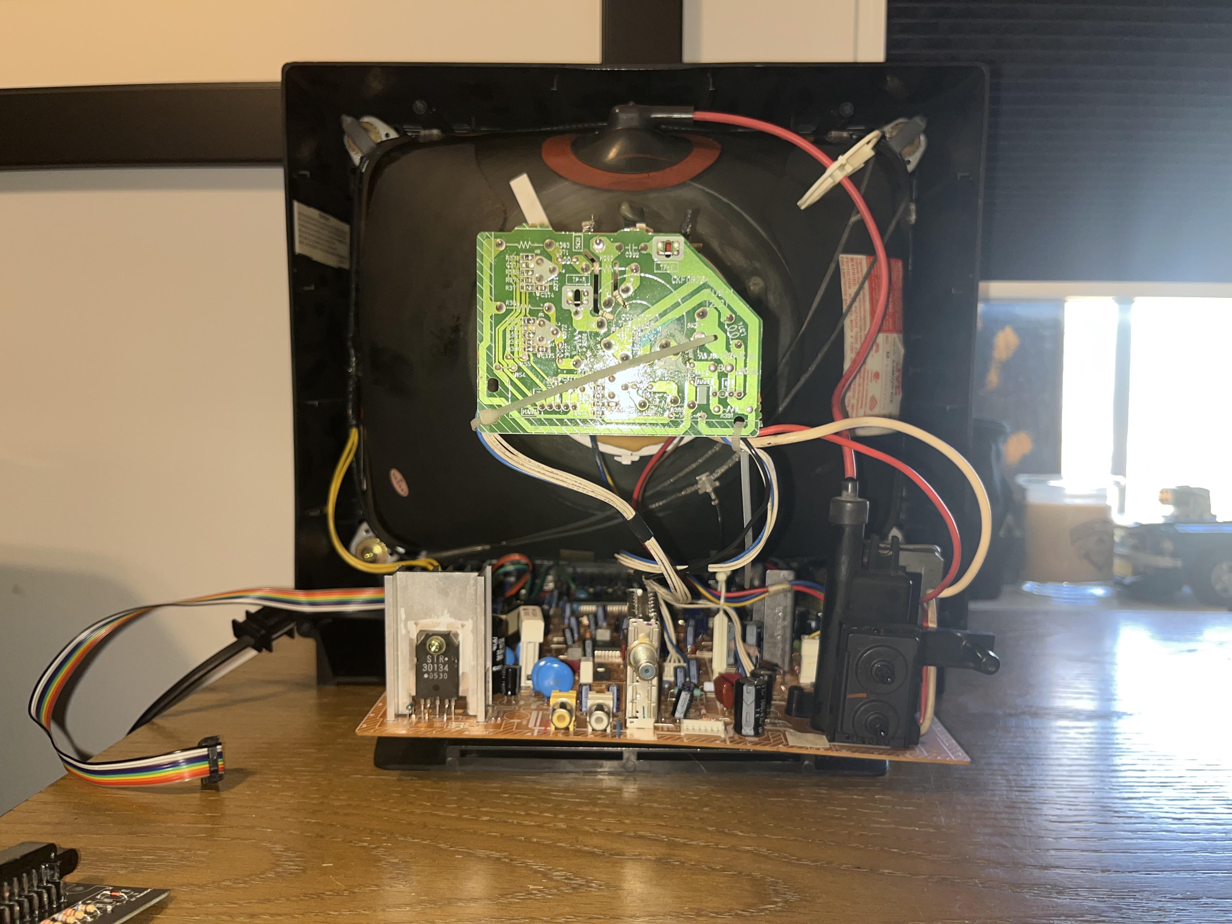
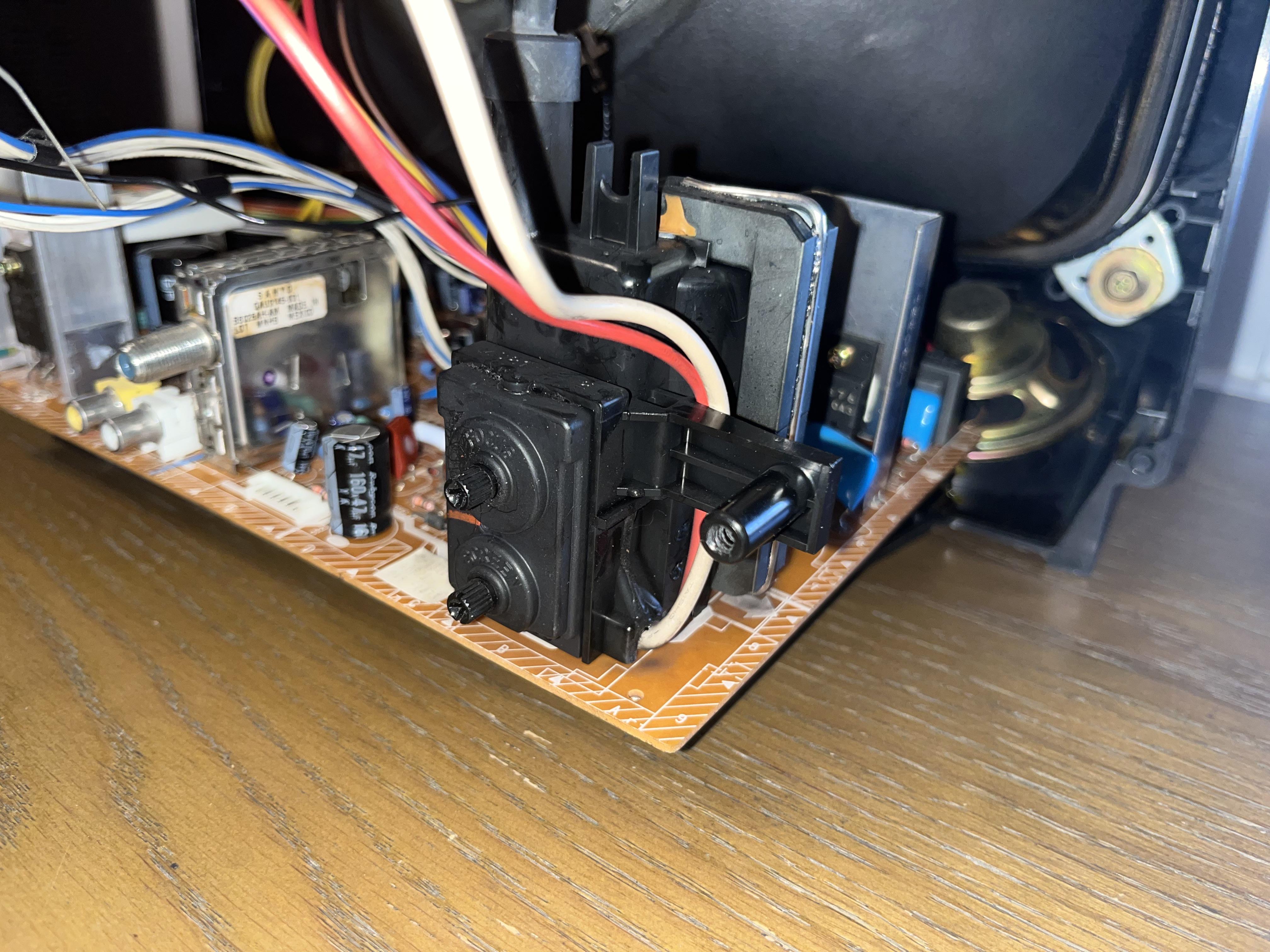
Performing the mod
Now that you roughly know what needs to be done, prepare for the mod. Place the board on a comfortable place. Make sure you are not putting pressure on the flyback or other components.
STEP 1: Remove the following components
Remove the following components. RGB resistors to the ground. Measure twice and mark before you remove.
- R738 (1 kohm)
- R740 (1 kohm)
- R742 (1 kohm)
STEP 2: Connect RGBs, Blanking and Audio
This TV doesn't have a schematic to show this on a diagram. But, the picture below shows where the wires should be soldered. R, G, B wires should be soldered to the -ve terminals of the C801, C802, C803 capacitors respectively.
Blanking wire can be attached directly on Pin 14 of the chroma chip.
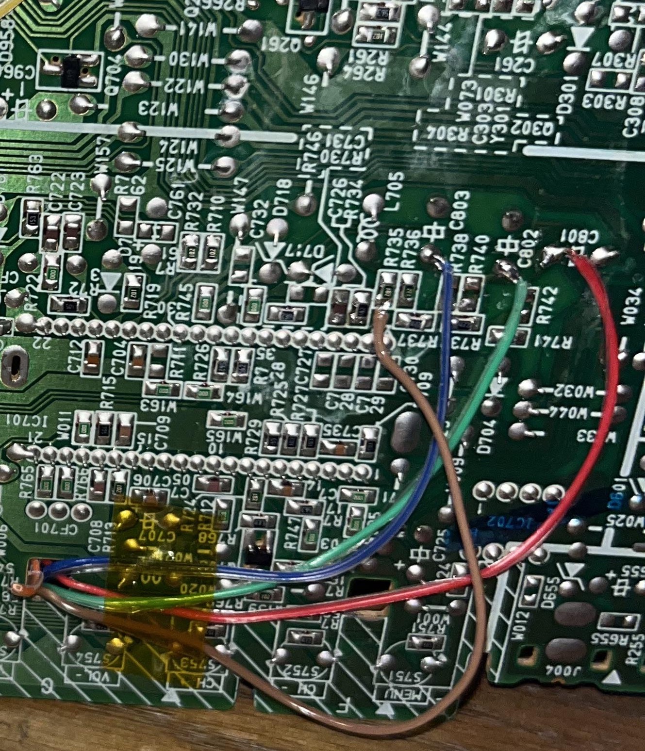
Route the wires through the hole 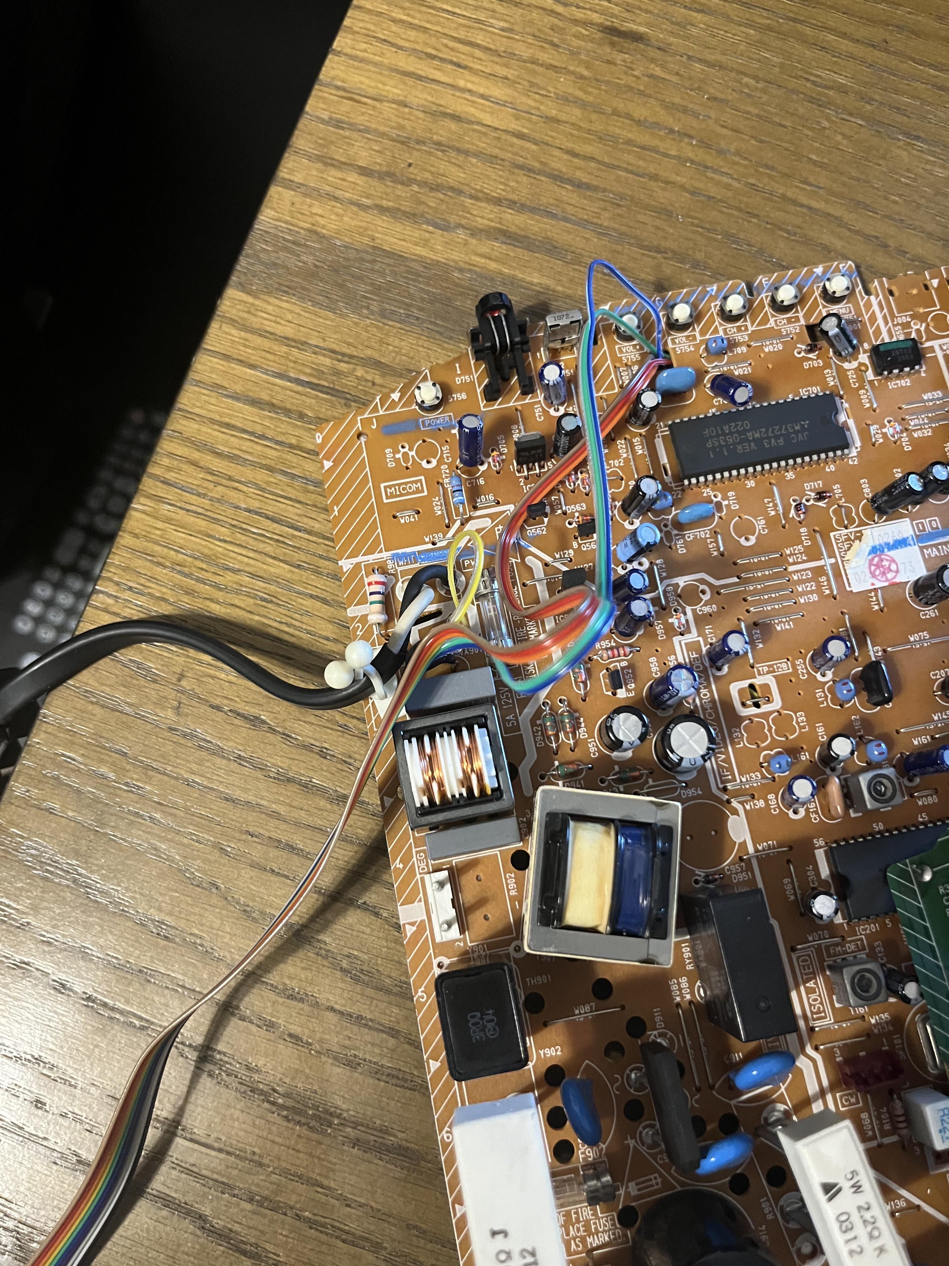
Audio and ground wires 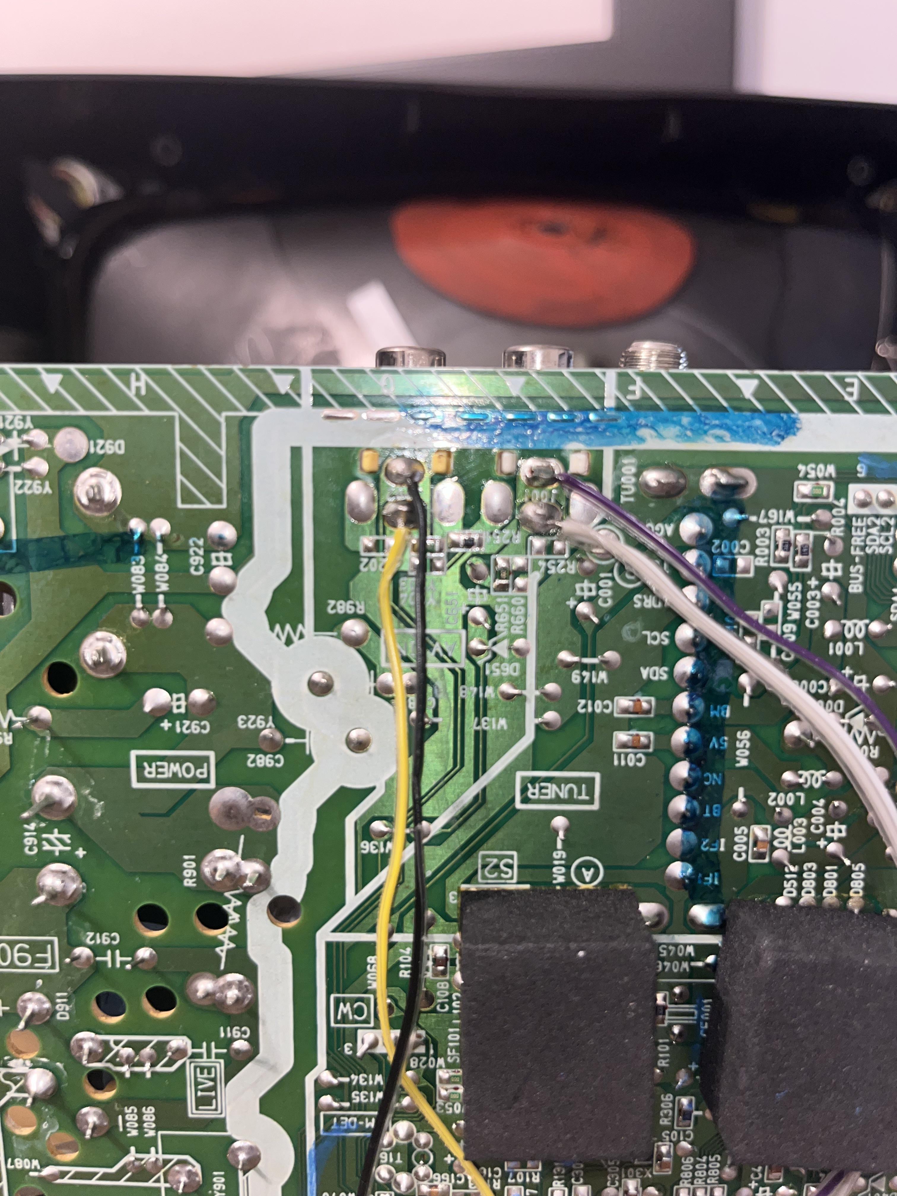
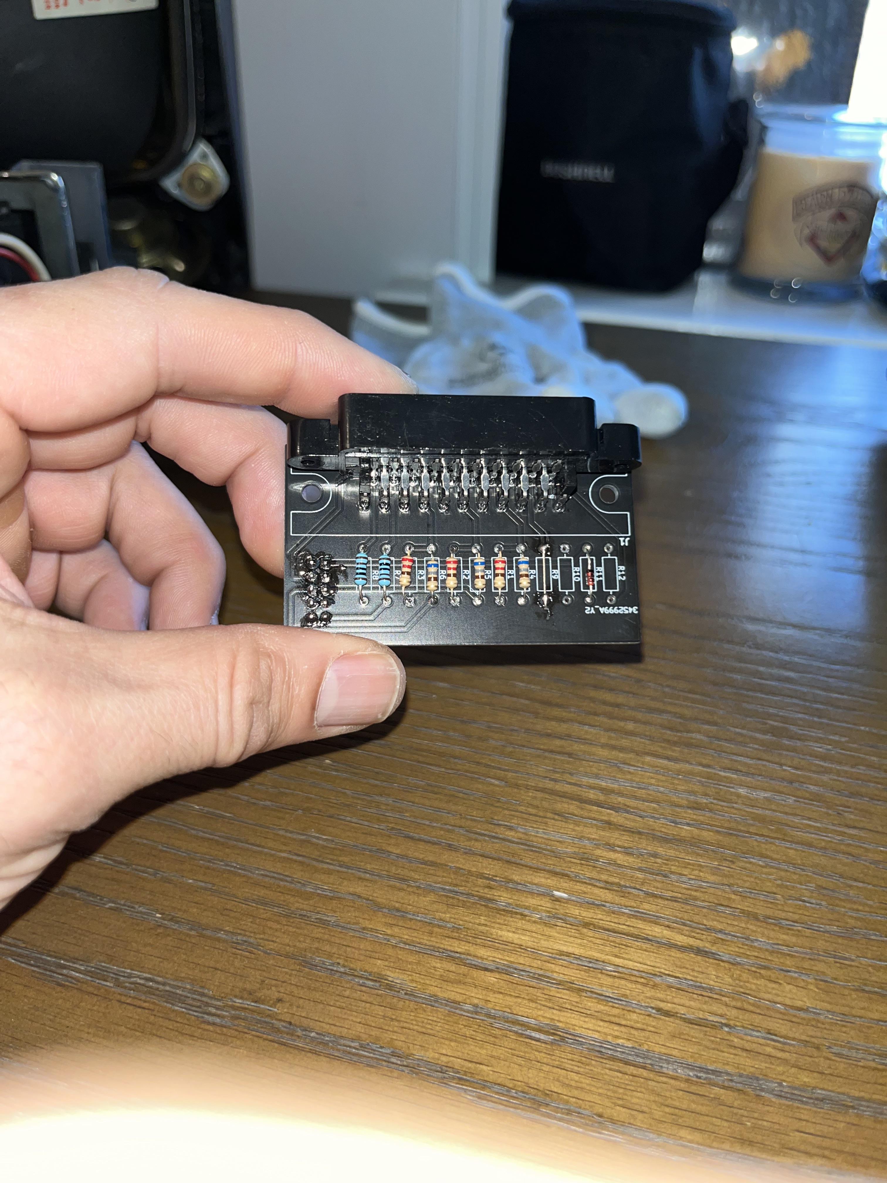
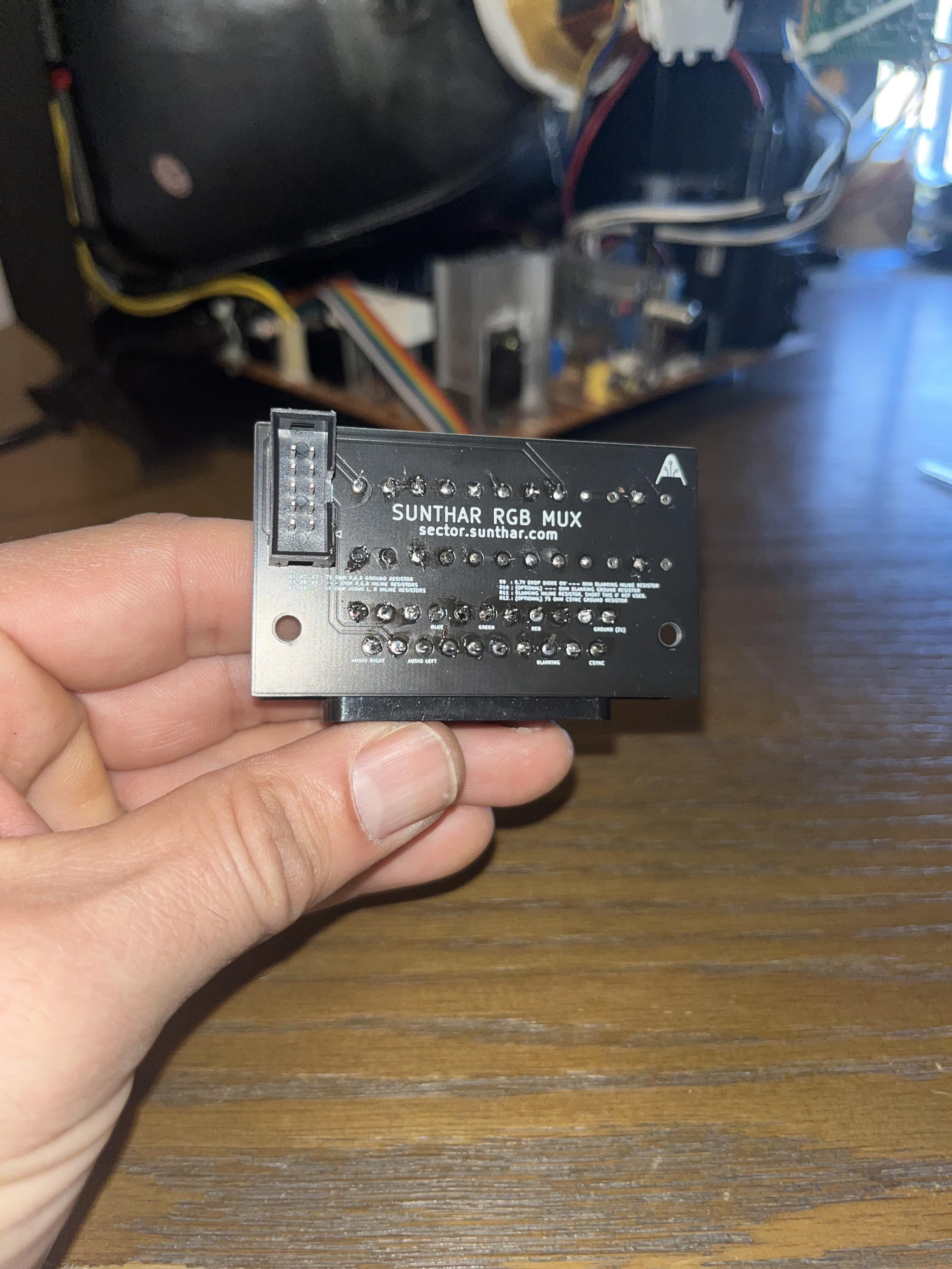
STEP 3: Build your mux board
This mod uses the RGB mux board. This is optional, but will make your mod easier and stable. You can also create the circuit presented in the schematics above without the board. Please also checkout the mux calculator to play with your own values.
| Component | Value |
|---|---|
| RGB/OSD inline resistor (chassis) | 3.9kΩ |
| Removed RGB/OSD resistor (chassis) | 1kΩ |
| 0.1μF caps replaced (chassis) | Yes |
| RGB termination (R1, R2, R3) | 75Ω |
| RGB inline (R4, R5, R6) | 1kΩ |
| Audio LR (R7, R8) | 1kΩ |
| Diode (R9) | 1N4148 |
| Blanking Ground Resistor (R10) | open |
| Blanking Resistor (R11) | 2.2kΩ |
Compatible mux boards: RGB MUX BOARD KIT 1.4C, RGB MUX BOARD KIT 1.4B
STEP 4: Attach the female SCART connector to TV
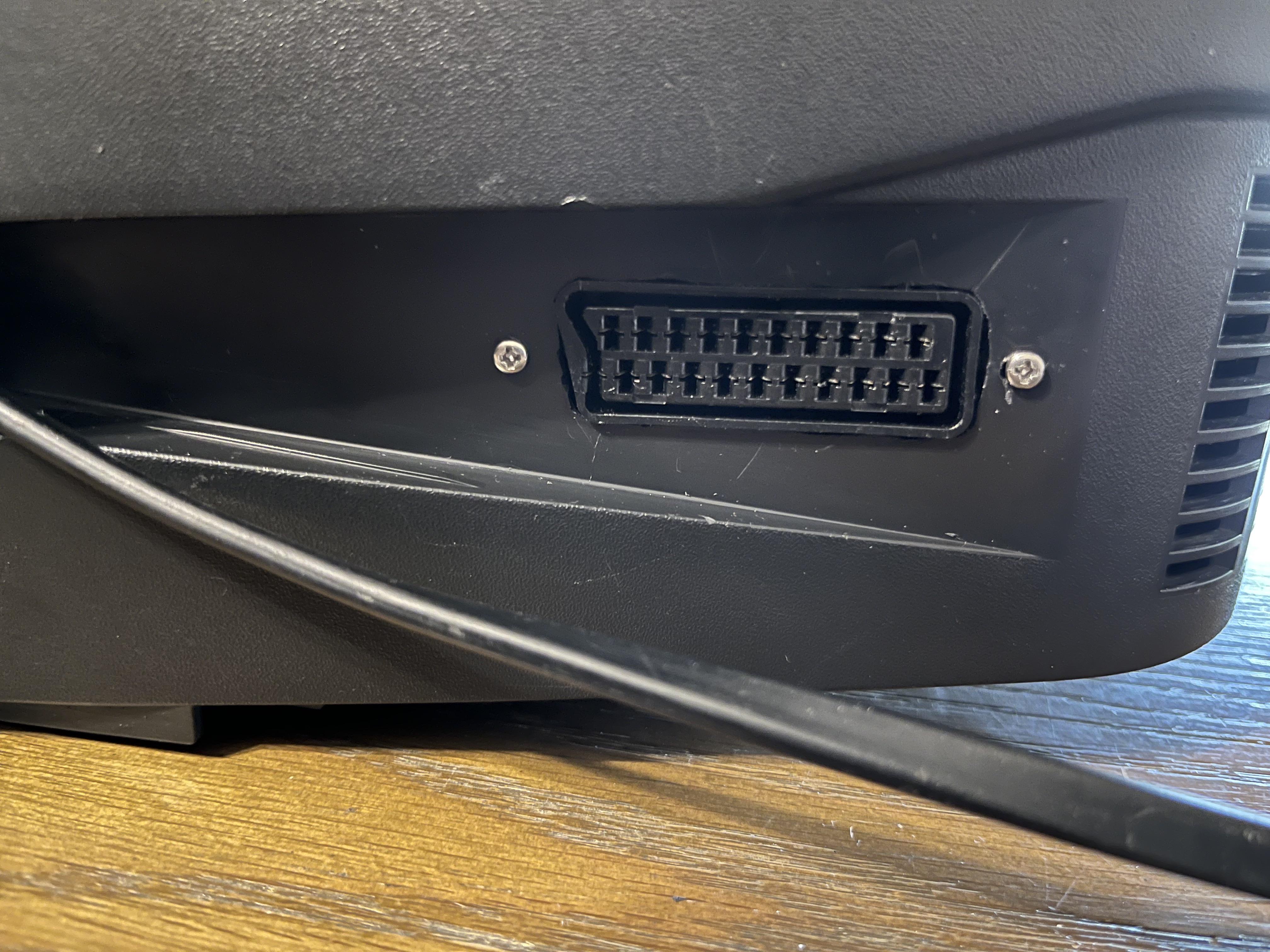
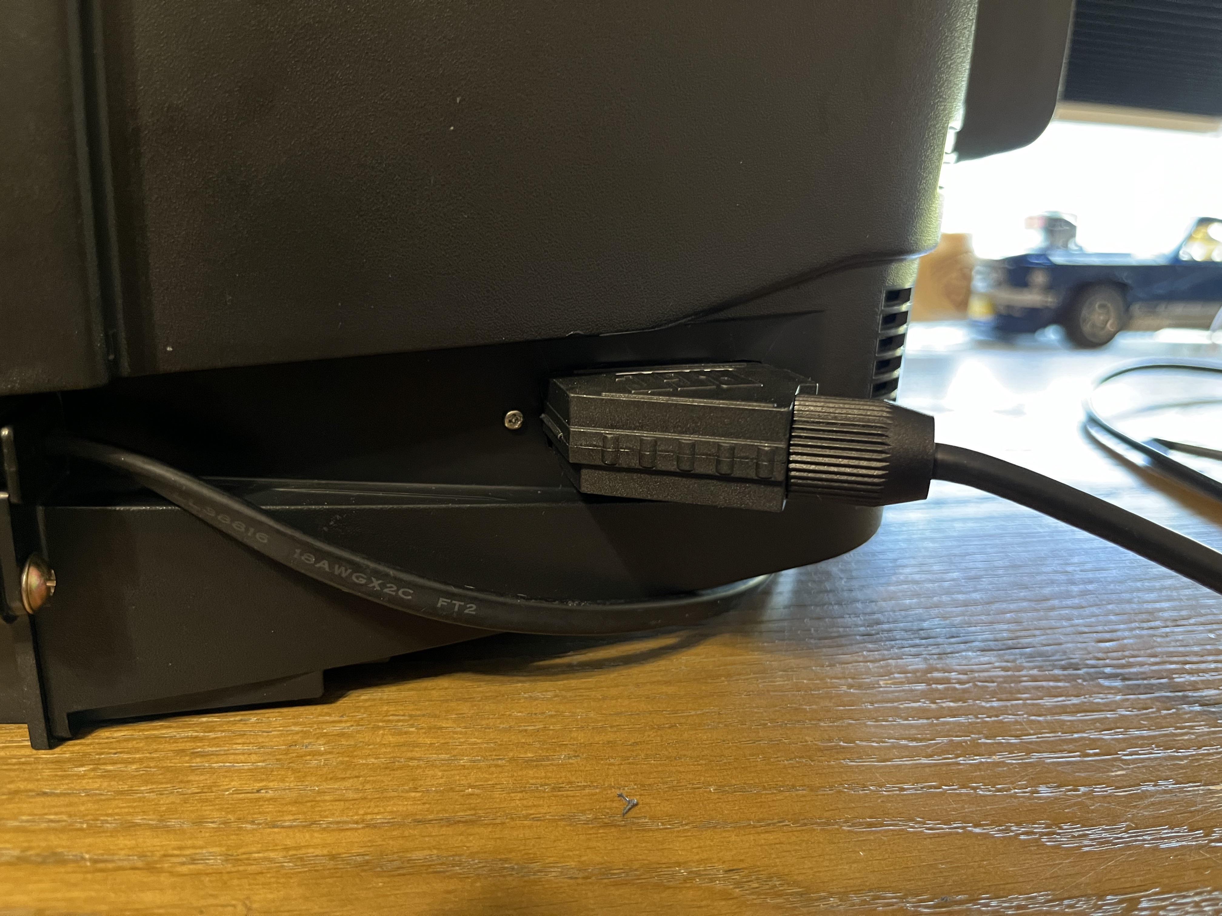
Creating a SCART cutout and mounting it is an art. I have a dedicated section for it.
How to create and mount a SCART female plug?
Remote control and service menu
You need the JVC branded remote to get into the service menu. Pressing both the "Video Status" + "Display" buttons together on the remote brings up the service menu.
You will need to adjust the Horizontal Position slightly with the RGB input.
- JVC RM-C540
- JVC RM-C542
Pictures of the mod
Main Chassis
Full Board Back
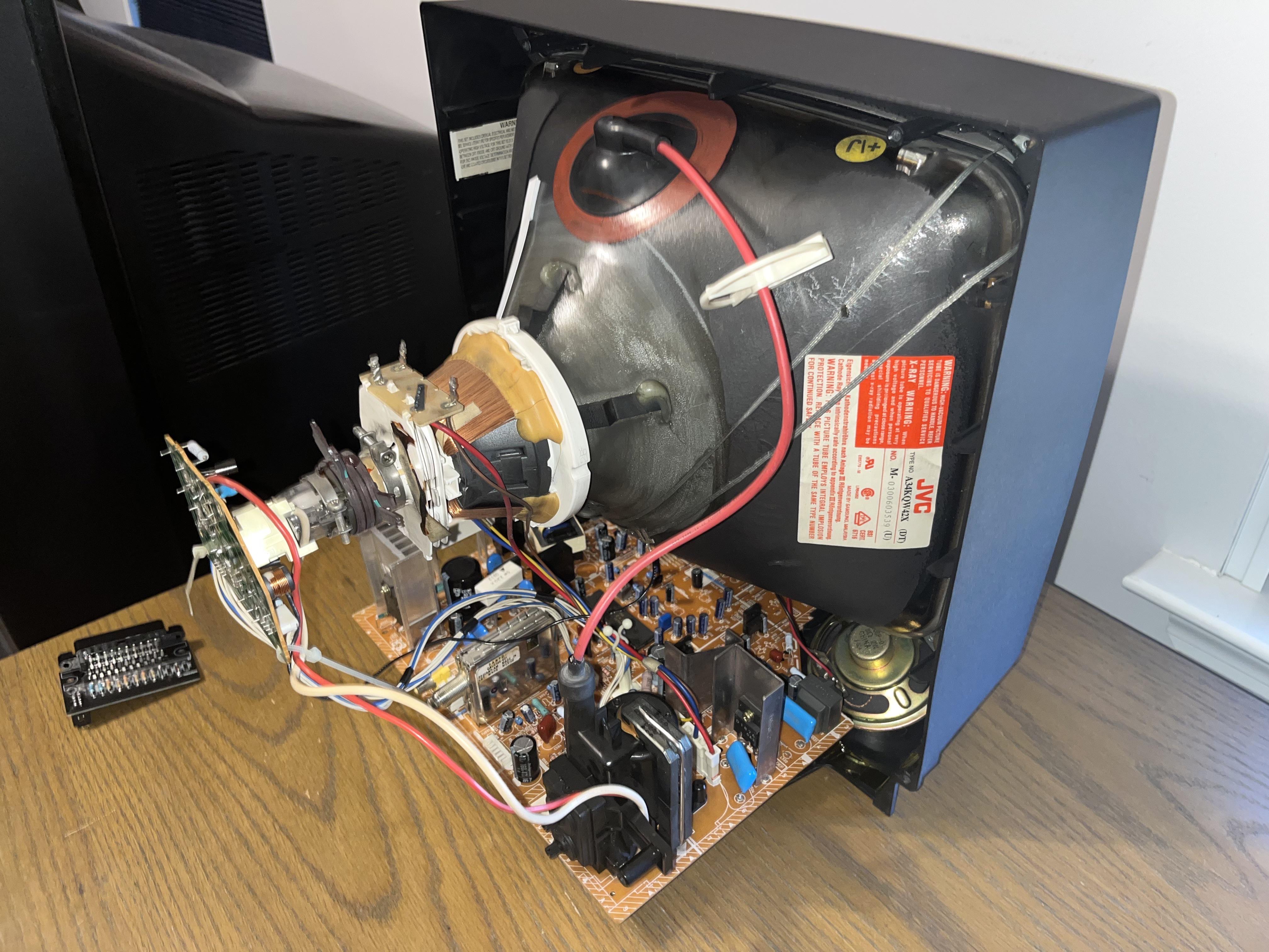
Tube
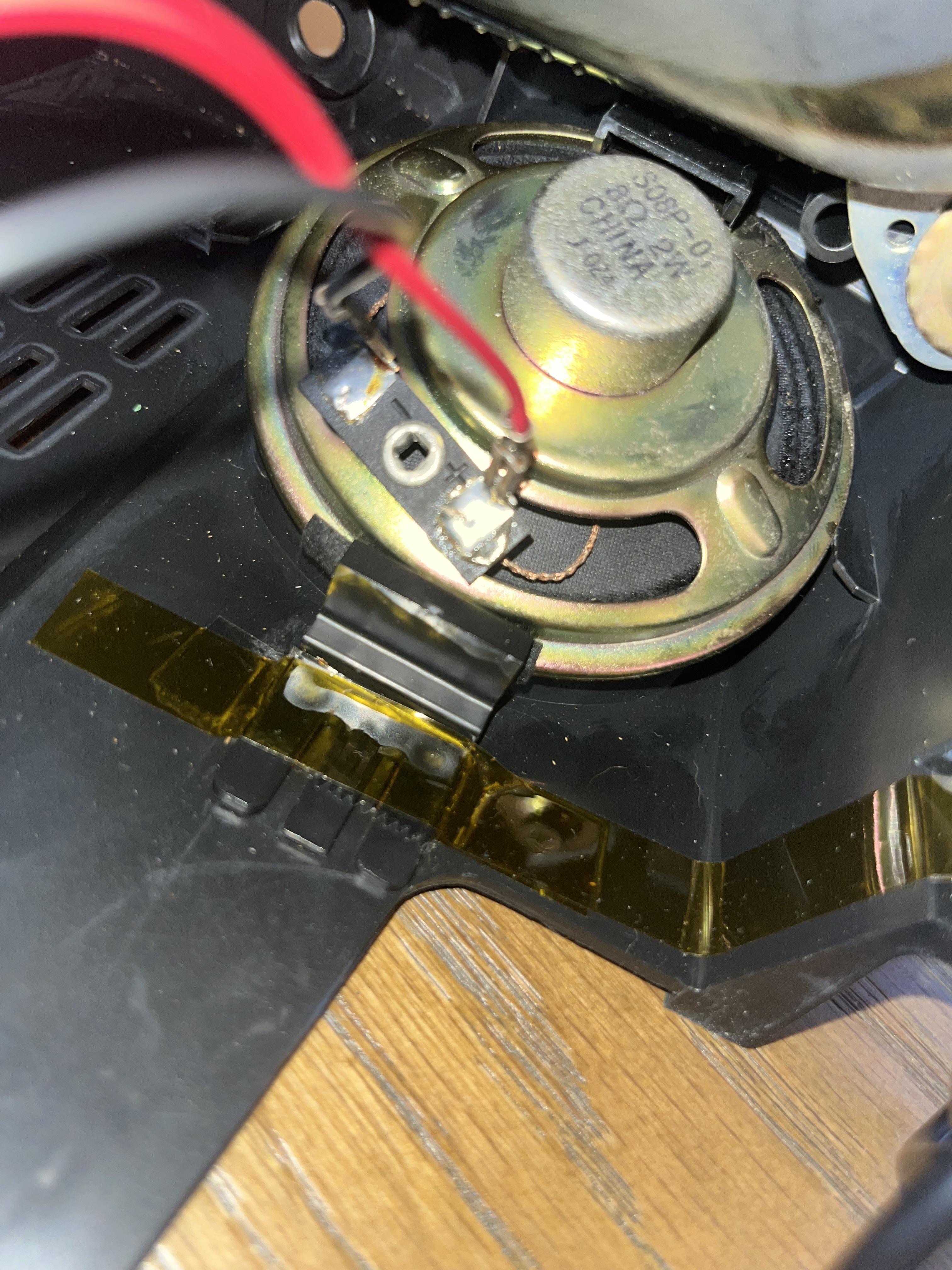
Speaker
Neck board
Flyback
CRT Back Label
Patterns
OSD Overlay
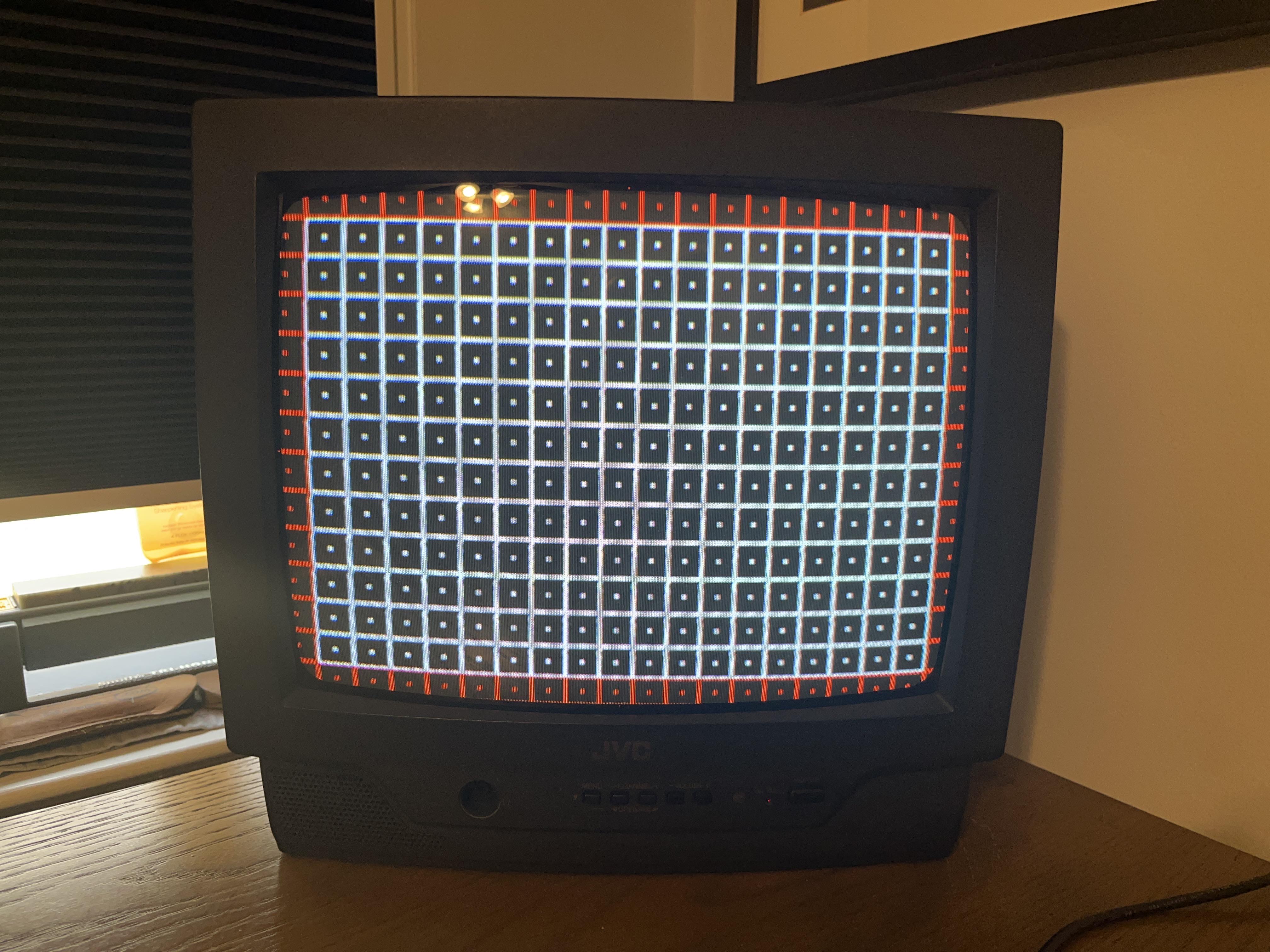
Grid
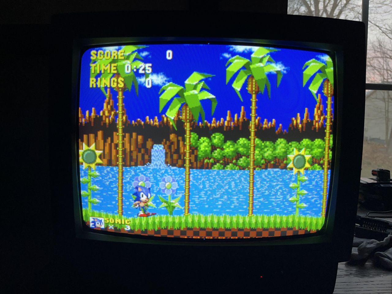
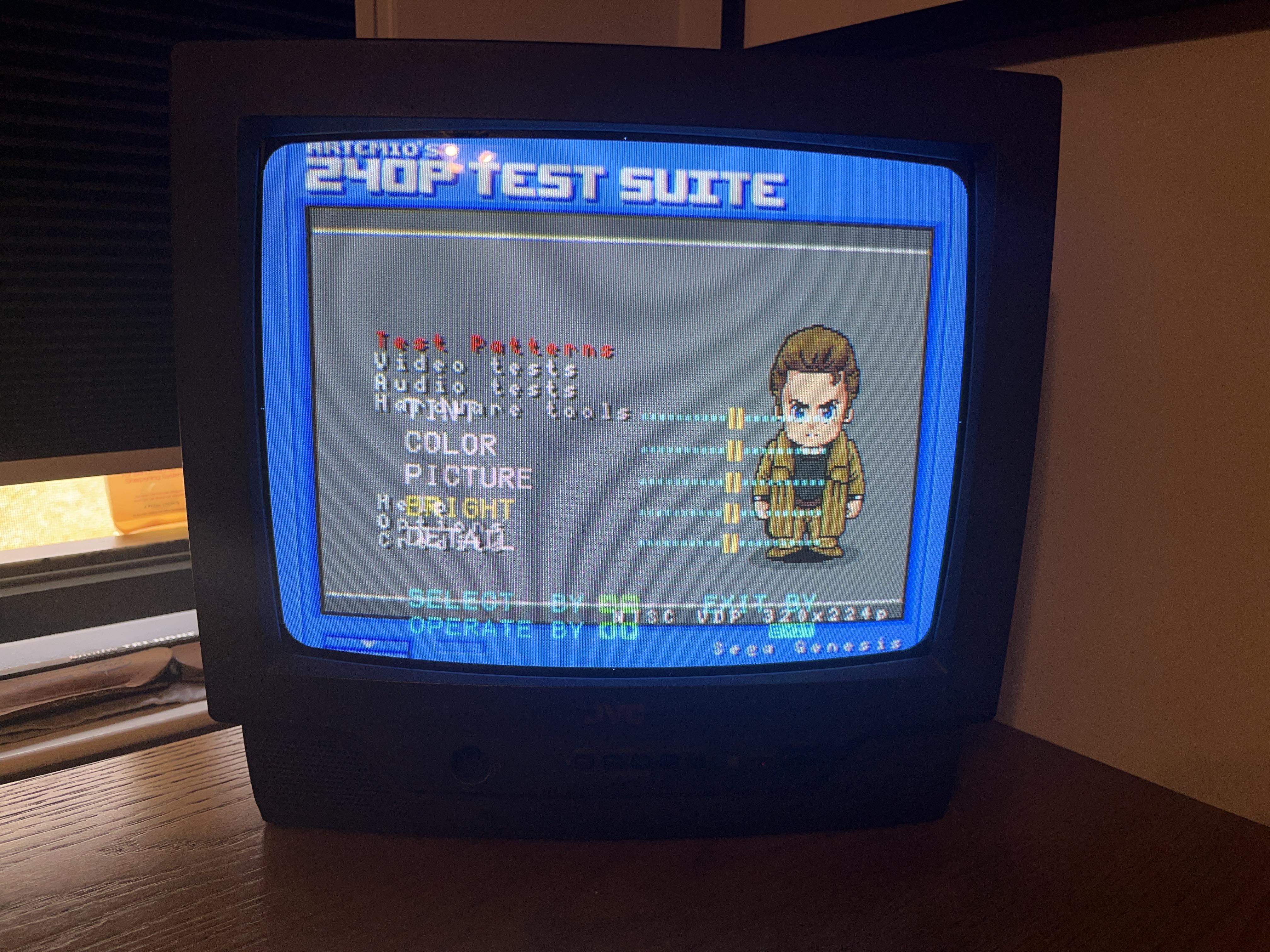
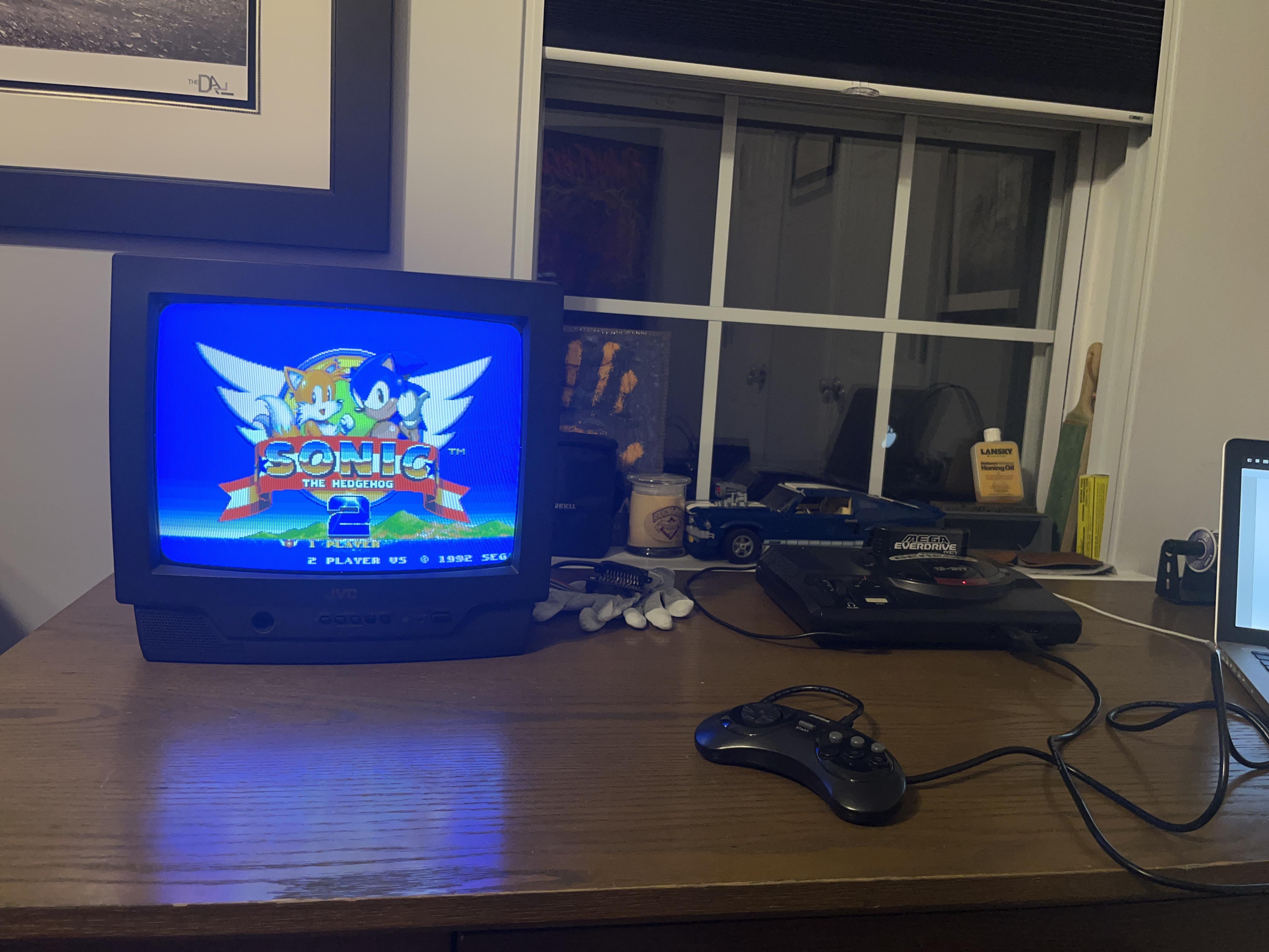
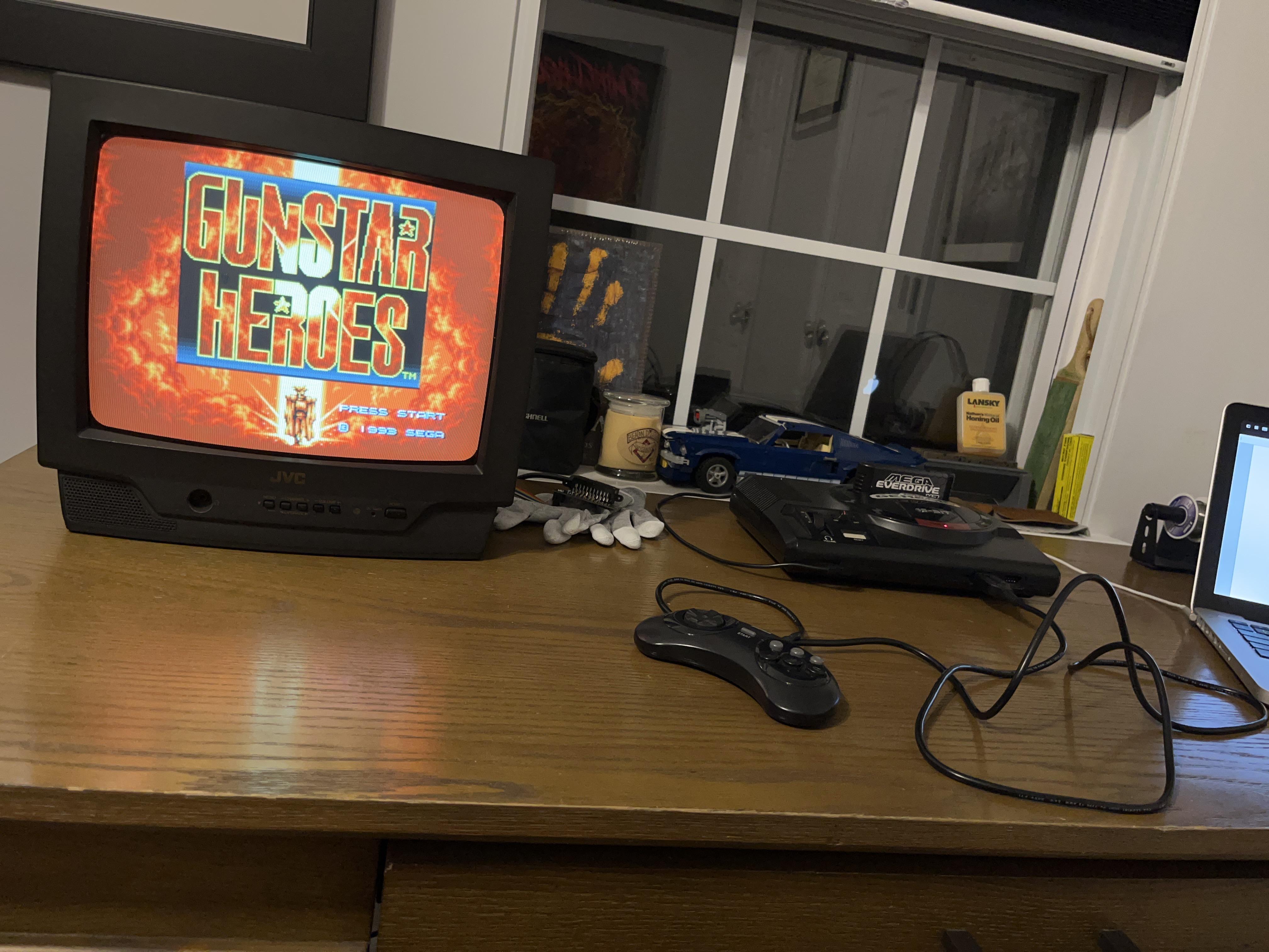
Games
Sega Genesis - Sonic

Pictures
Reference Photos