RCA E13320
RCA E13320 CRT RGB mod
This article was originally written by Martin Seibert and later enhanced with additional details by Sunthar.
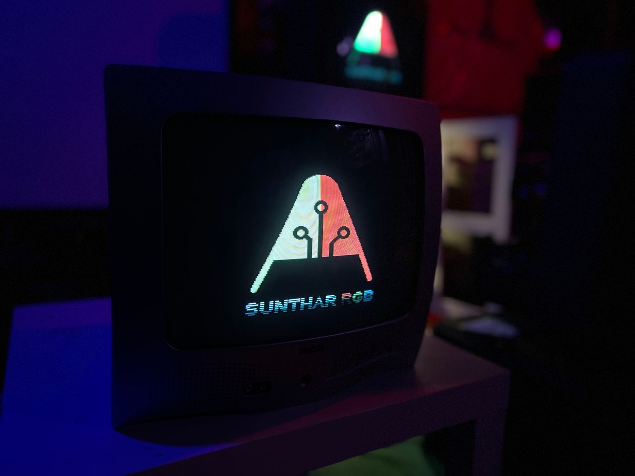
RGB modded RCA E13320. More details here

View full CRT details and more mod examples →
Contributors
Thank you to everyone who contributed to this guide:
- Sunthar — photos and documentation
- Robert McCoy's Sector — photos and documentation
- Matt Ross — contributor, CRT specs from CRT Database.
- Martin Seibert — contributor, Original RGB mod article
CRT safety
Caution
You can die doing this! So read carefully! CRT TV is not a toy. Do not open a CRT TV. If you don't have any prior knowledge about handling high voltage devices, this guide is not for you. CRT TV contains high enough voltage (20,000+ V) and current to be deadly, even when it is turned off.
Plan of attack
Manuals and Datasheets
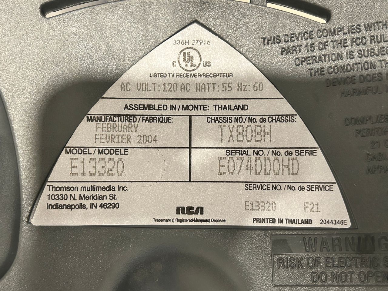
Specs
- Year: 2003
- Format: NTSC
- Chassis: TX808H
- Tube: RCA 37GDA86X
- Jungle Chip: Toshiba TA1268N
- OSD Chip: STMicroelectronics ST9294J5B1
- Screen Size: 13"
- Inputs: Composite, RF
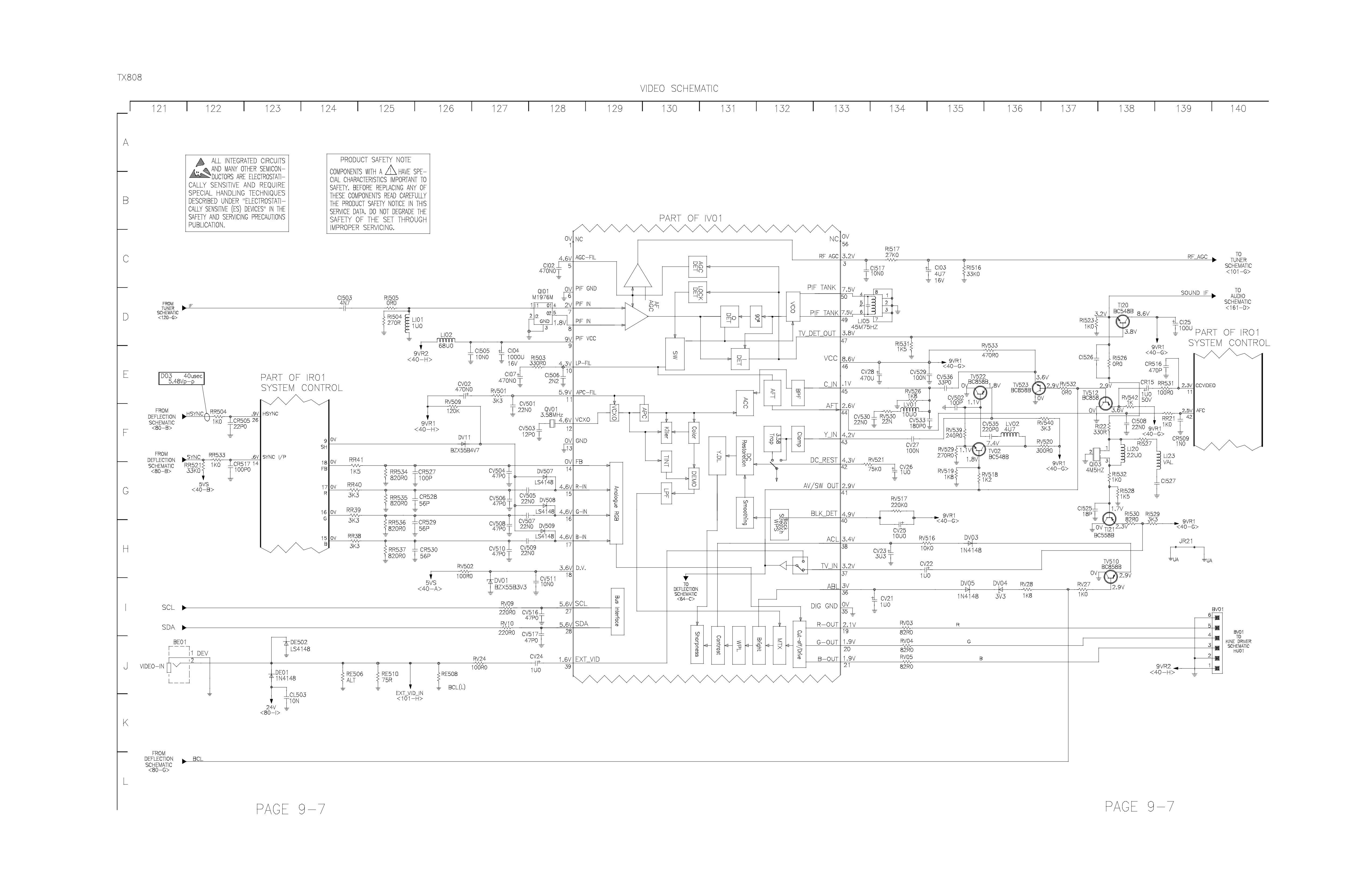
RGB mux diagram
Prepare the mux diagram. If you are building your own circuit, this diagram should help.
Schematics
Performing the mod
Micro kit is recommended for a cleaner installation.
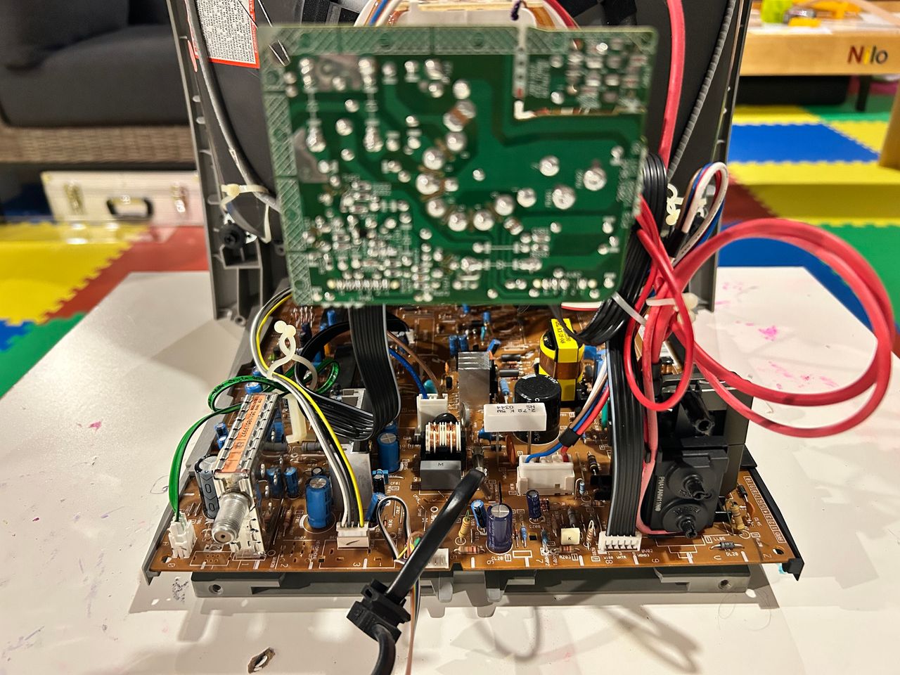
There are 6 screws to remove. 4 shown in the below picture. 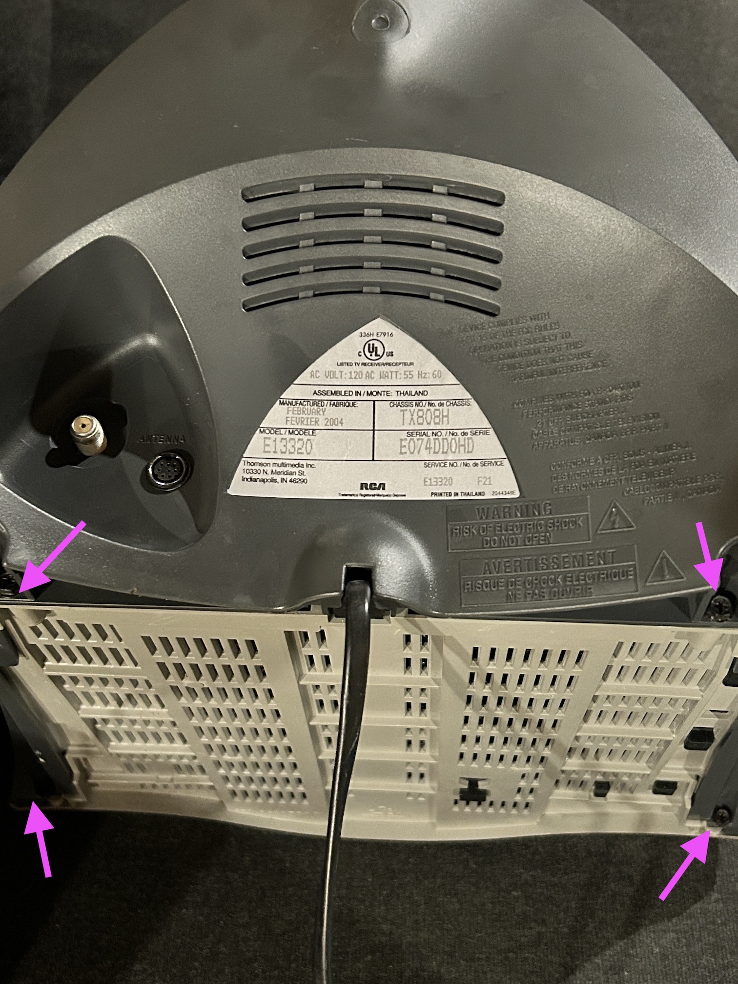
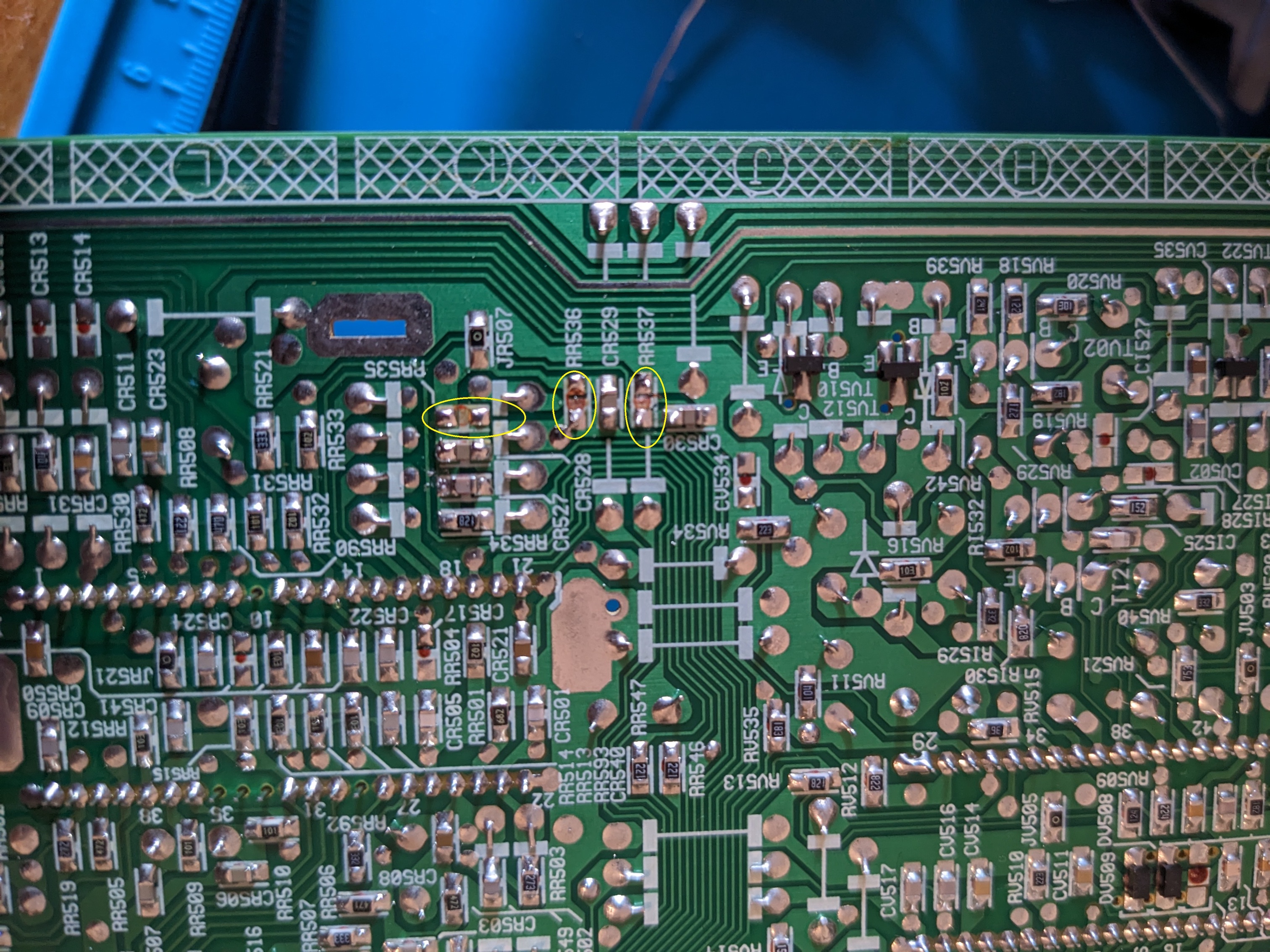
STEP 1: Remove the following components
Remove the following RGB resistors that are connected to the ground.
- RR535
- RR536
- RR537
STEP 2: Add inline diodes to reduce interference
STEP 3: Connect RGB and Blanking
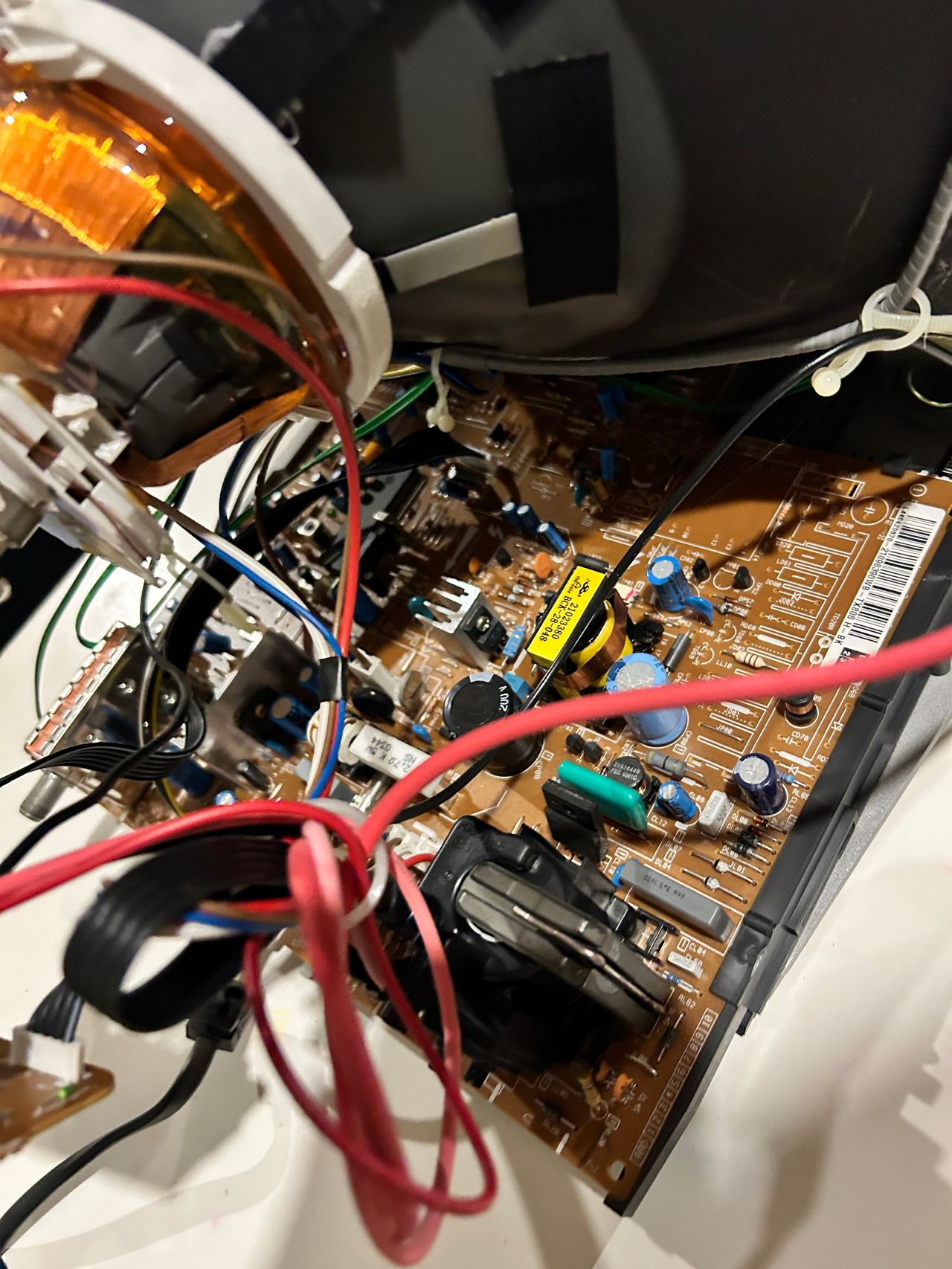
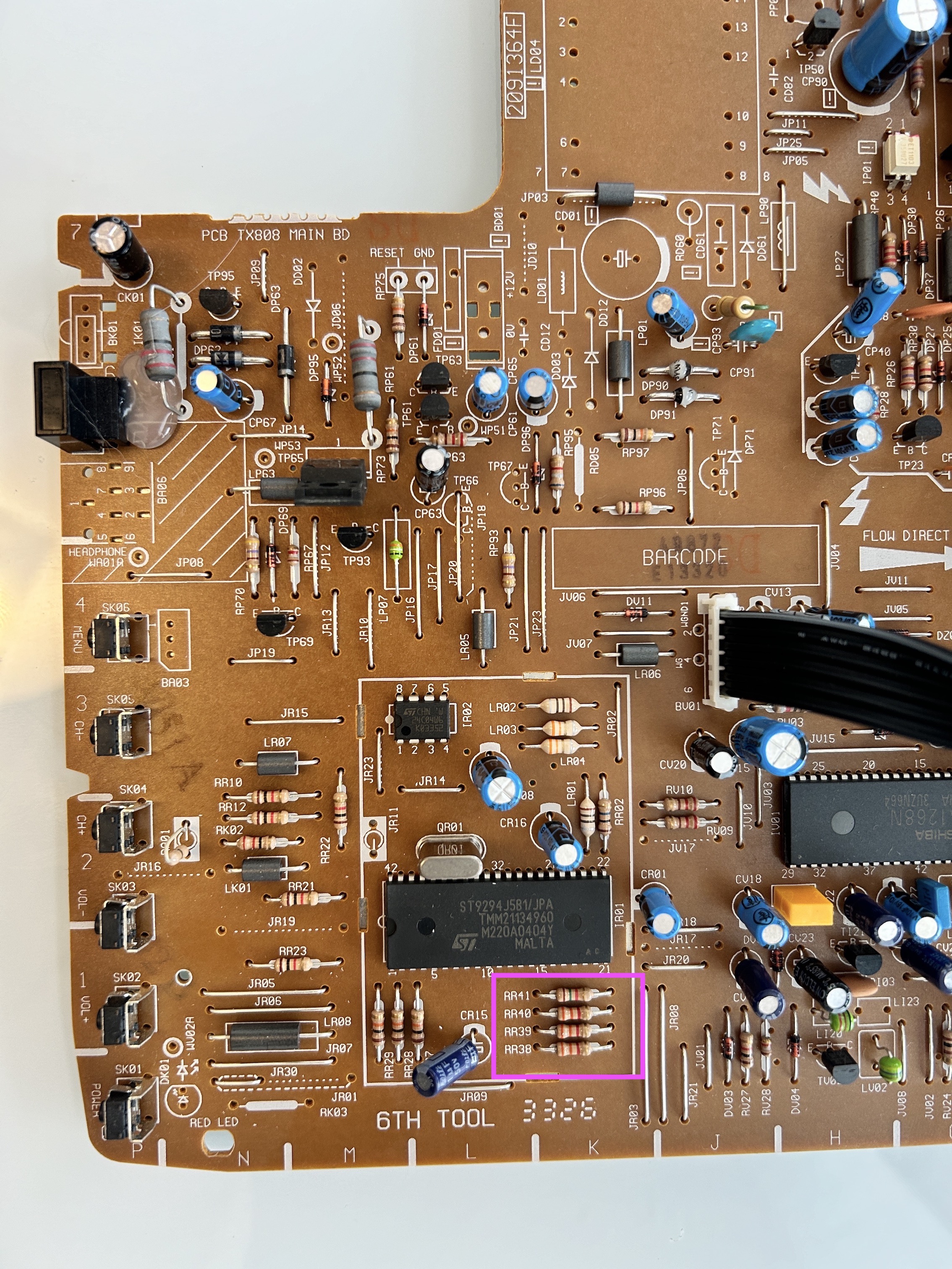
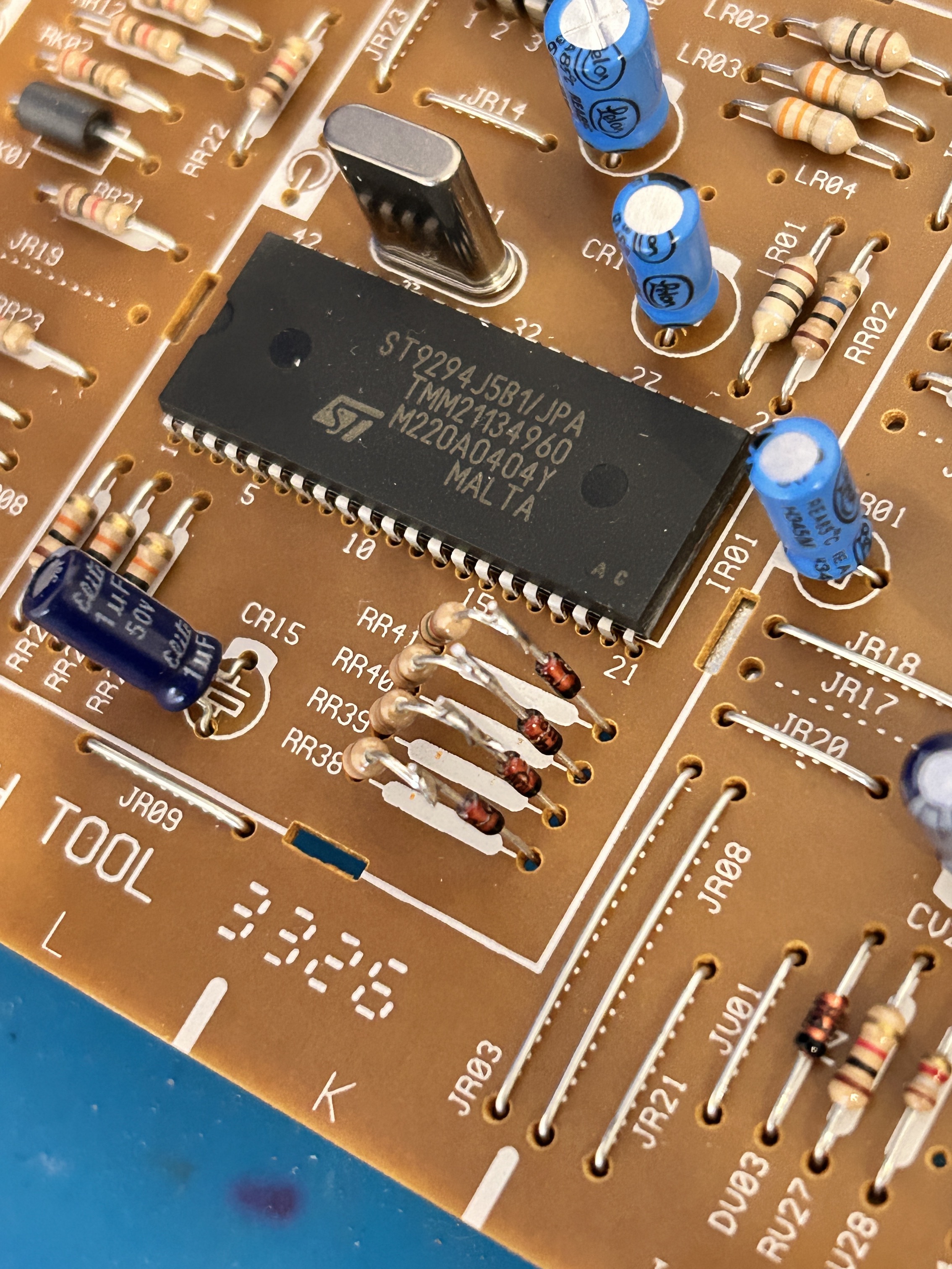
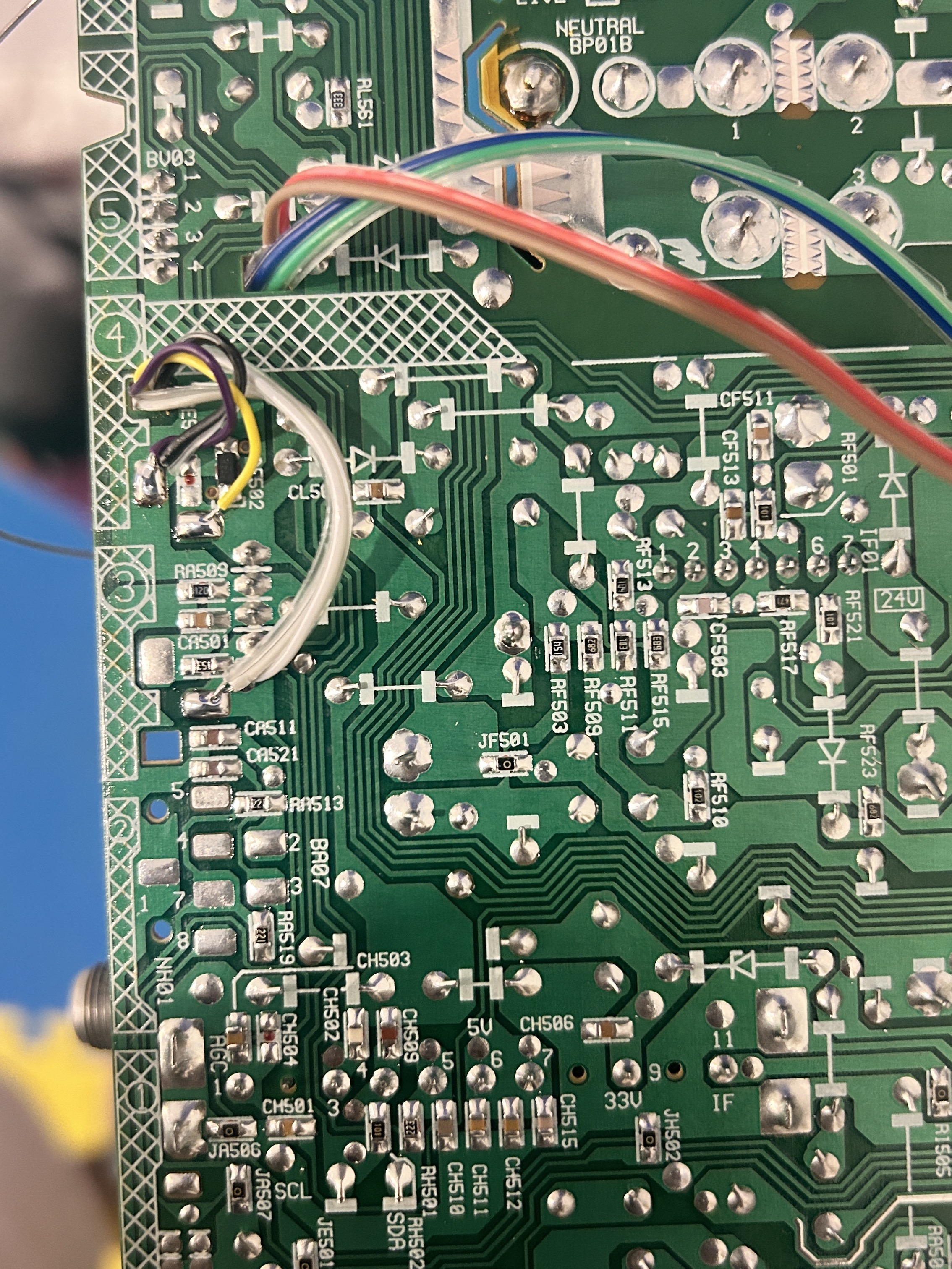
Picture below shows where the RGB and blanking wires should be soldered. ![]()
STEP 4: Connect Audio, Sync and Ground
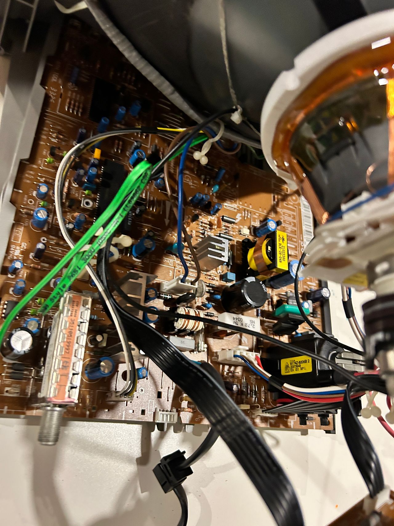
Composite Sync, Audio and Ground wires should be connected.
STEP 5: Build your mux board/circuit
This mod uses the RGB mux board. This is optional, but will make your mod easier and stable. You can also create the circuit presented in the schematics above without the board. Please also checkout the mux calculator to play with your own values.
| Component | Value |
|---|---|
| RGB/OSD inline resistor (chassis) | 3.3kΩ |
| Removed RGB/OSD resistor (chassis) | 820Ω |
| RGB inline diode method (chassis) | Yes |
| RGB termination (R1, R2, R3) | 180Ω |
| RGB inline (R4, R5, R6) | 820Ω |
| Audio LR (R7, R8) | 1kΩ |
| Diode (R9) | 1N4148 |
| Blanking Ground Resistor (R10) | open |
| Blanking Resistor (R11) | 1.2kΩ |
Compatible mux boards:
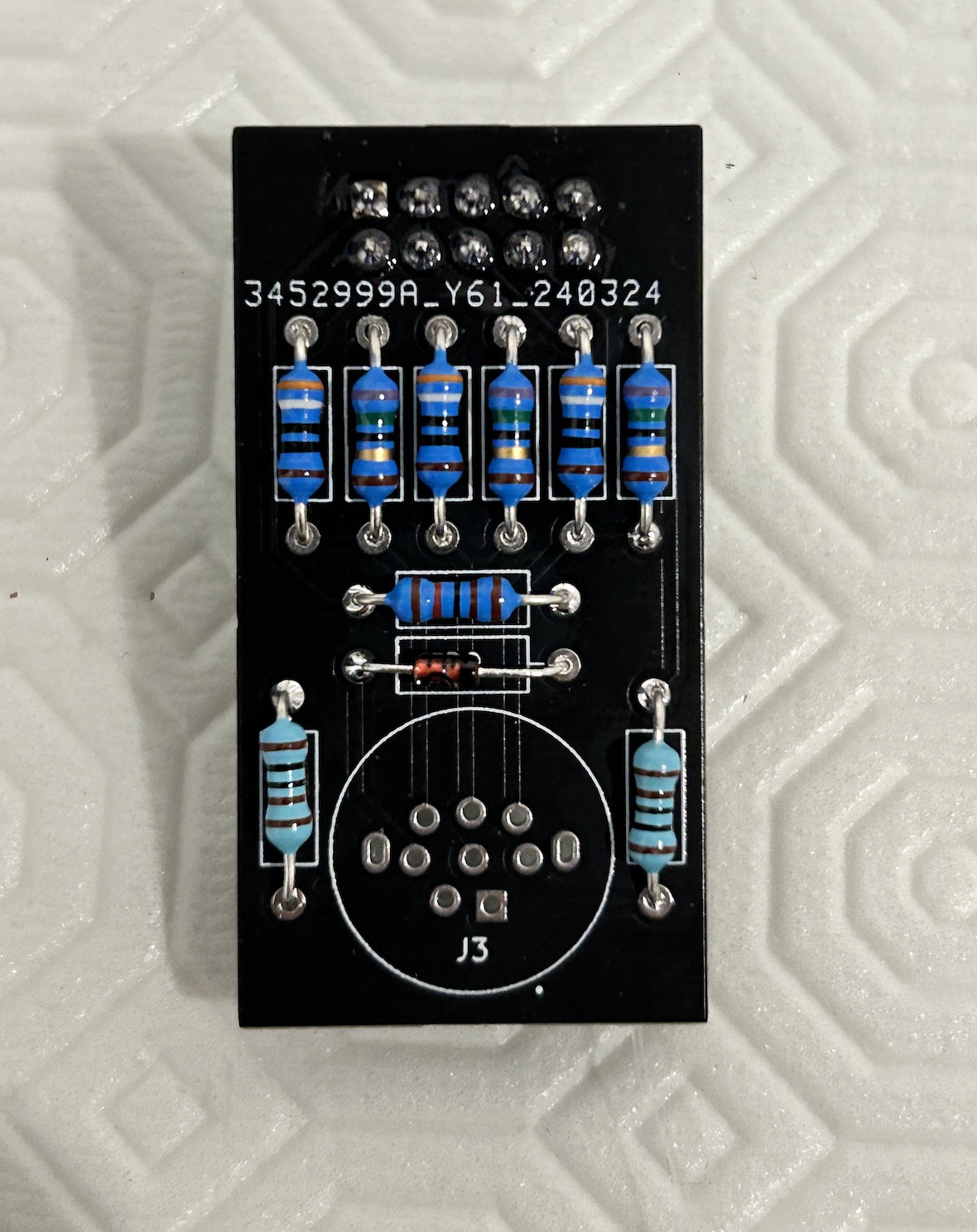
Below image is from the older standard mux board. New full scart mini mux board (1.3B) is slightly smaller than this. 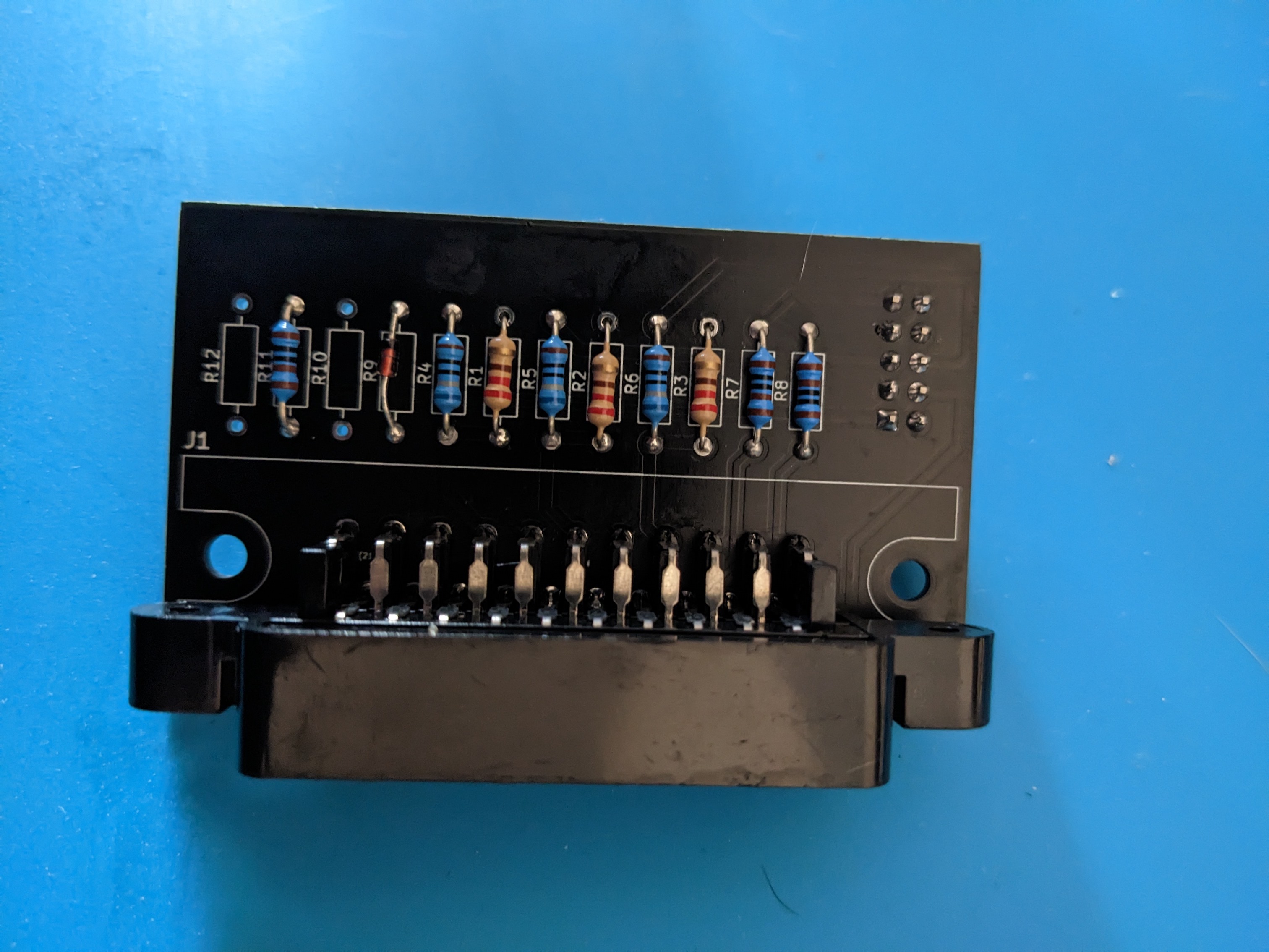
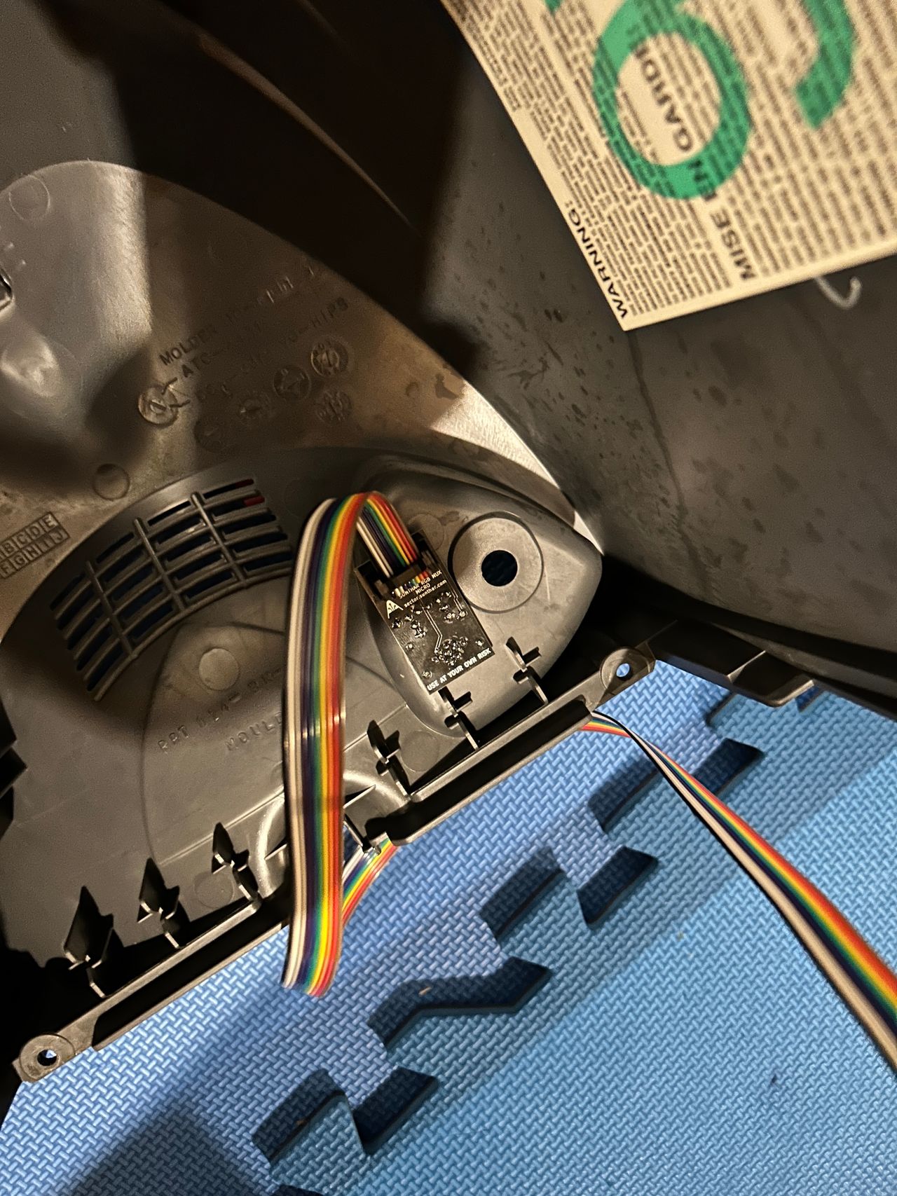
STEP 6: Attaching the micro board to your set
Drill a small hole. Make sure you have sufficient clearance and no obstructions especially when you close the chassis. You want to avoid areas where your tuner or flyback might interfere. 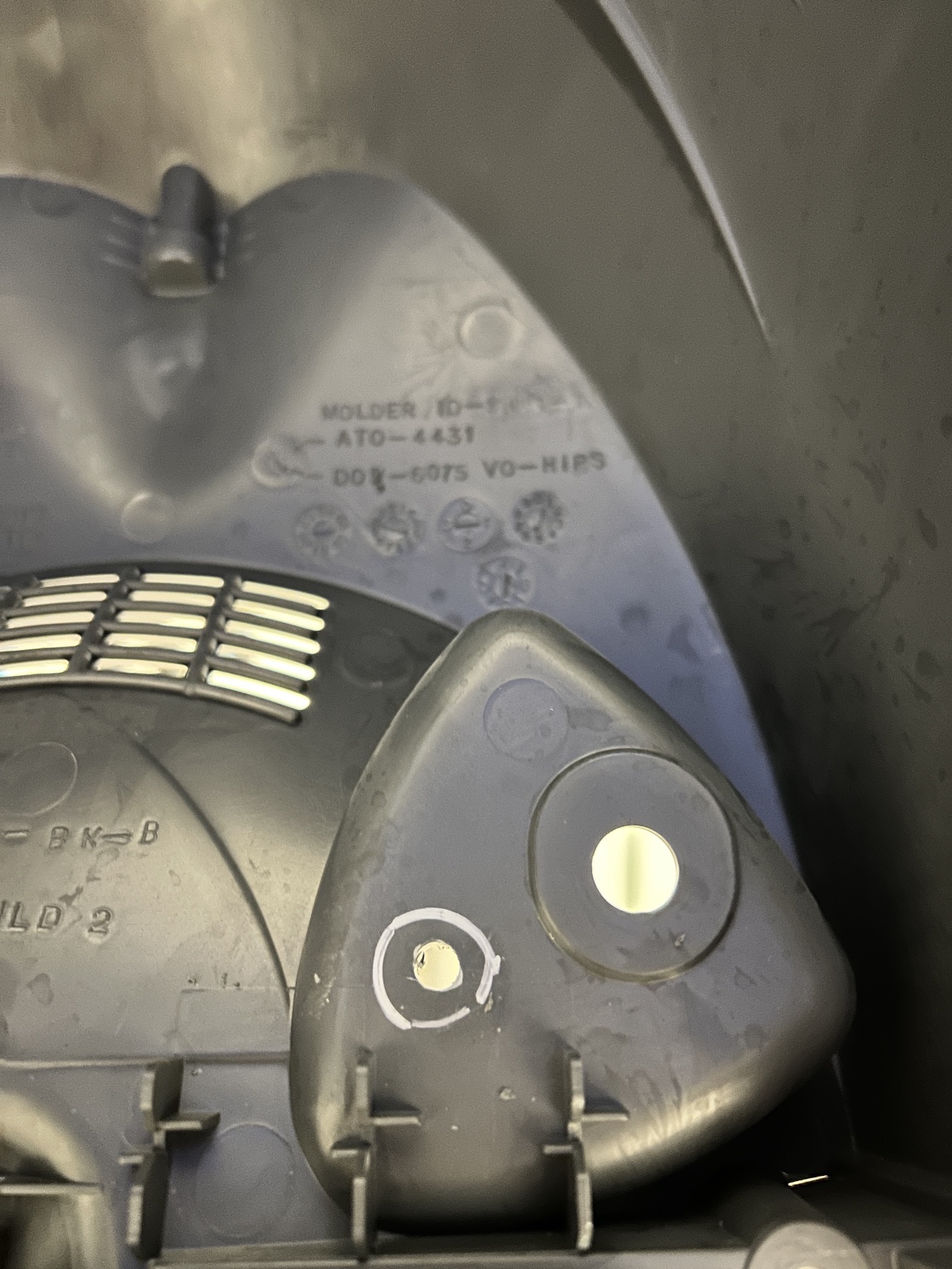
Expand the hole, just so that the MD8 feame header tightly fits in. If it is loose, then you'll have to epoxy or glue it later. Therefore, measure multiple times to make sure you find the tightest fit possible and avoid epoxy as much as possible. 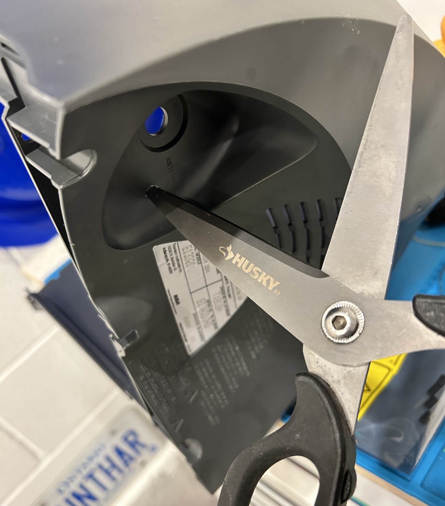
This is now ready for action. 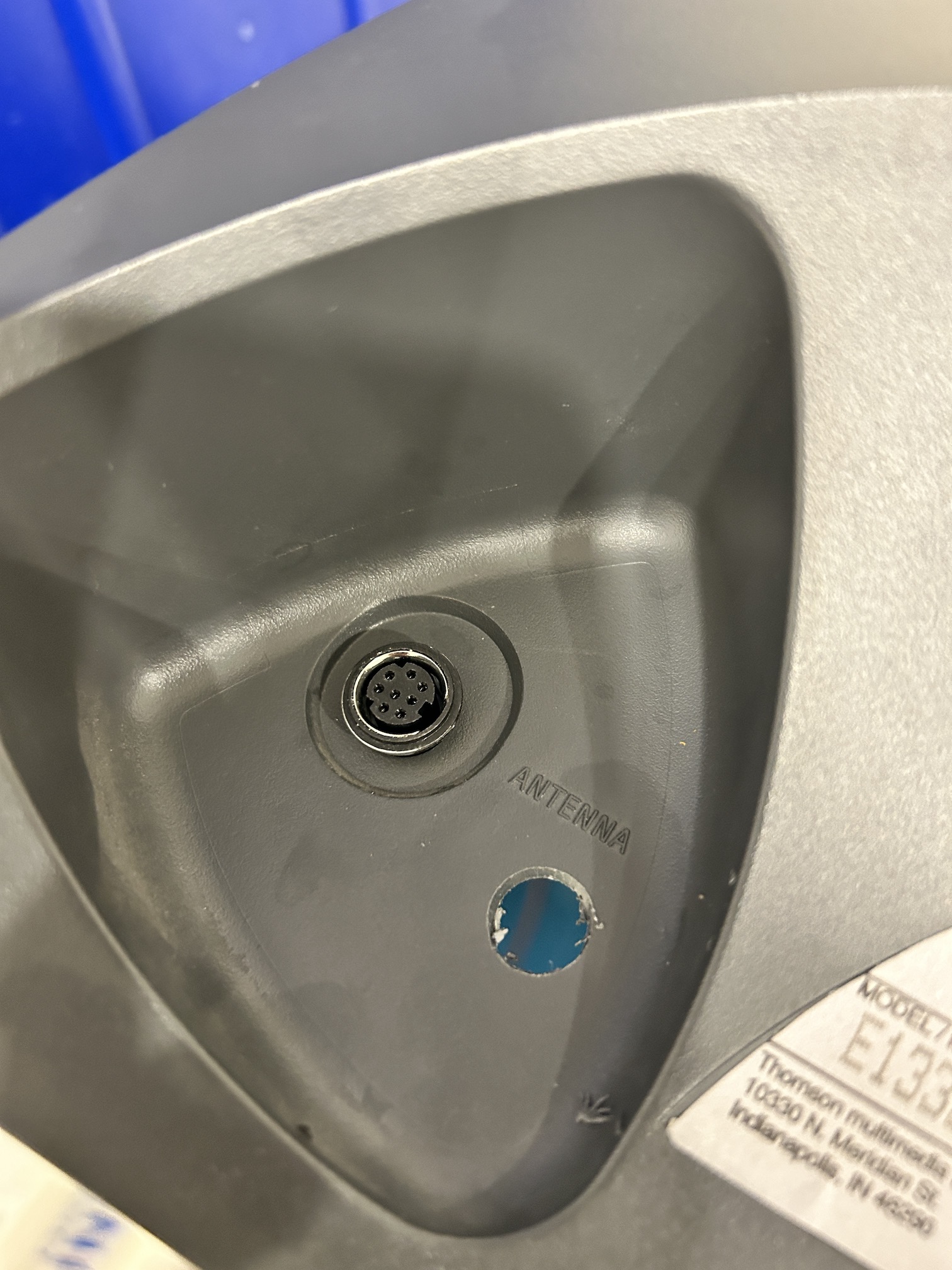
Push the MD8 connector through the hole. At this point, you can epoxy the MD8 connector optionally. 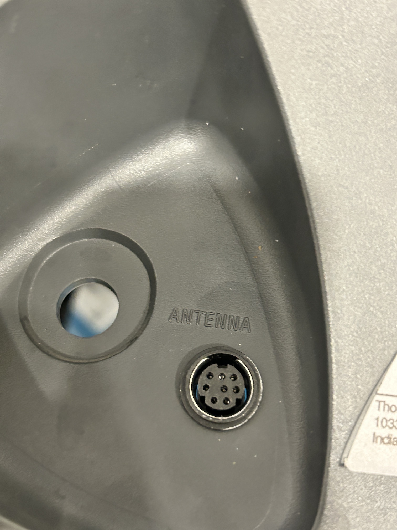
Assemble the board. See configuration above.
Now find a way to get the MD8 pins aligned, such that you can push the MD8 pins through the micro board. 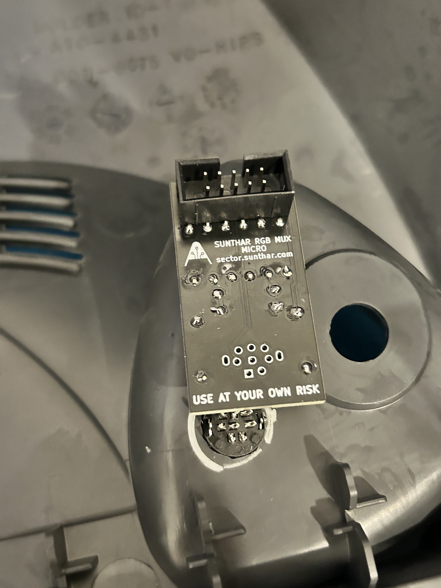
Solder the board. At this point MD8 connector won't fall inside or get fully removed. 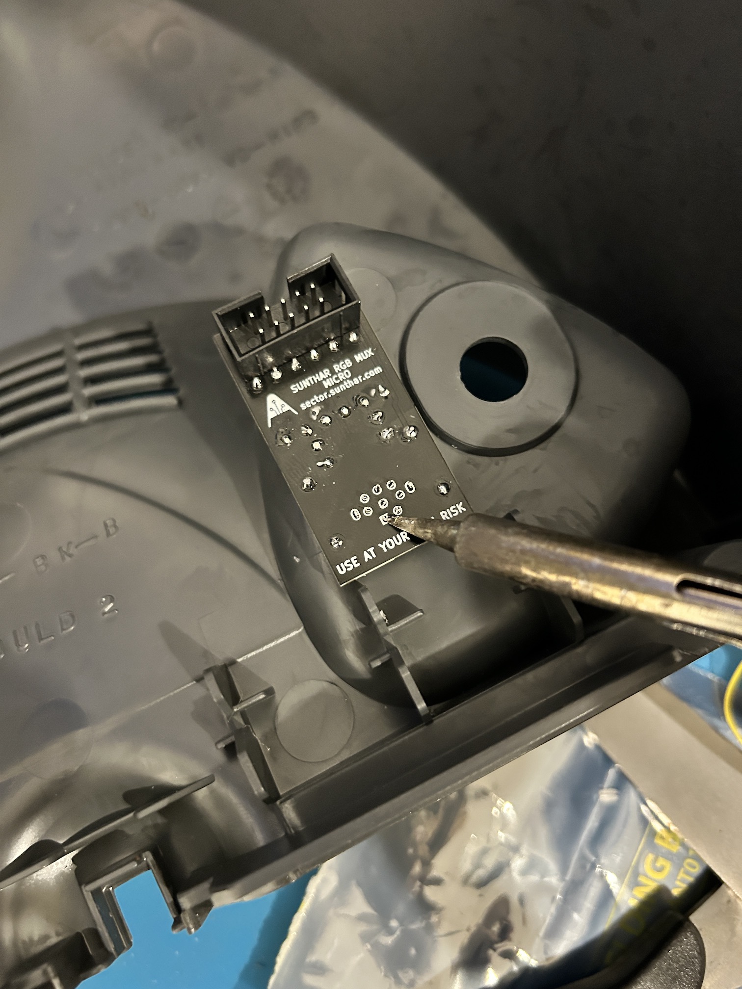
Connect the ribbon cable 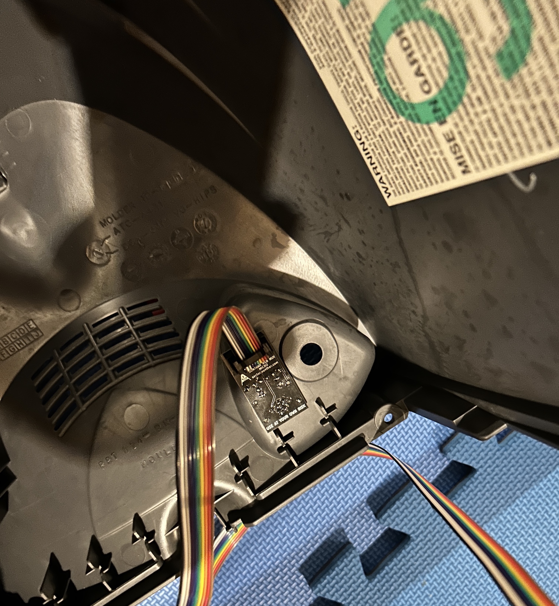
Close off the unit 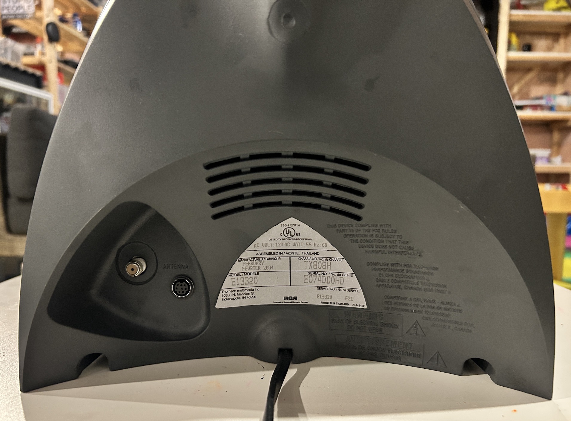
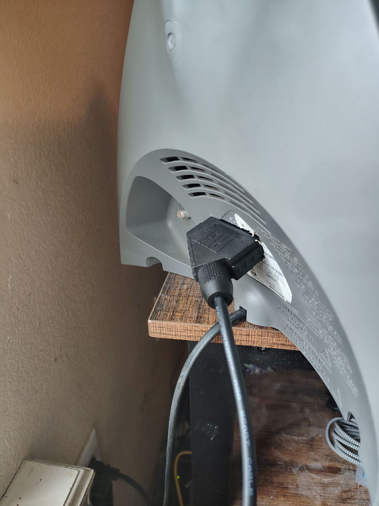
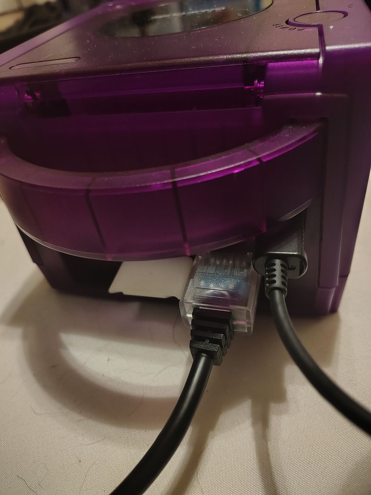
Finally, connect the MD8 to female SCART cable for some RGB action! 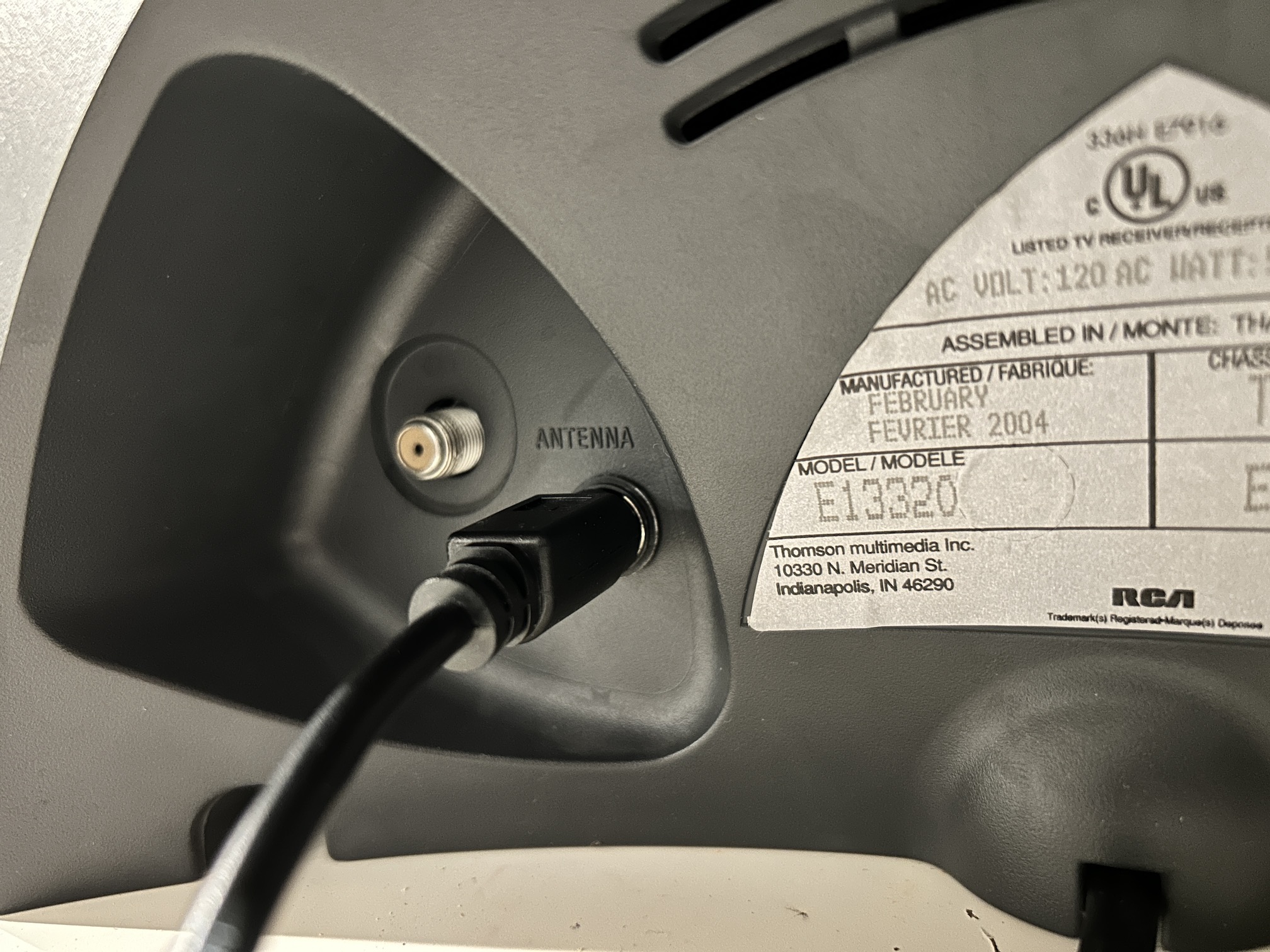
STEP 7: Attach the female SCART connector to TV
Creating a SCART cutout and mounting it is an art. I have a dedicated section for it.
You can also install the full SCART port. 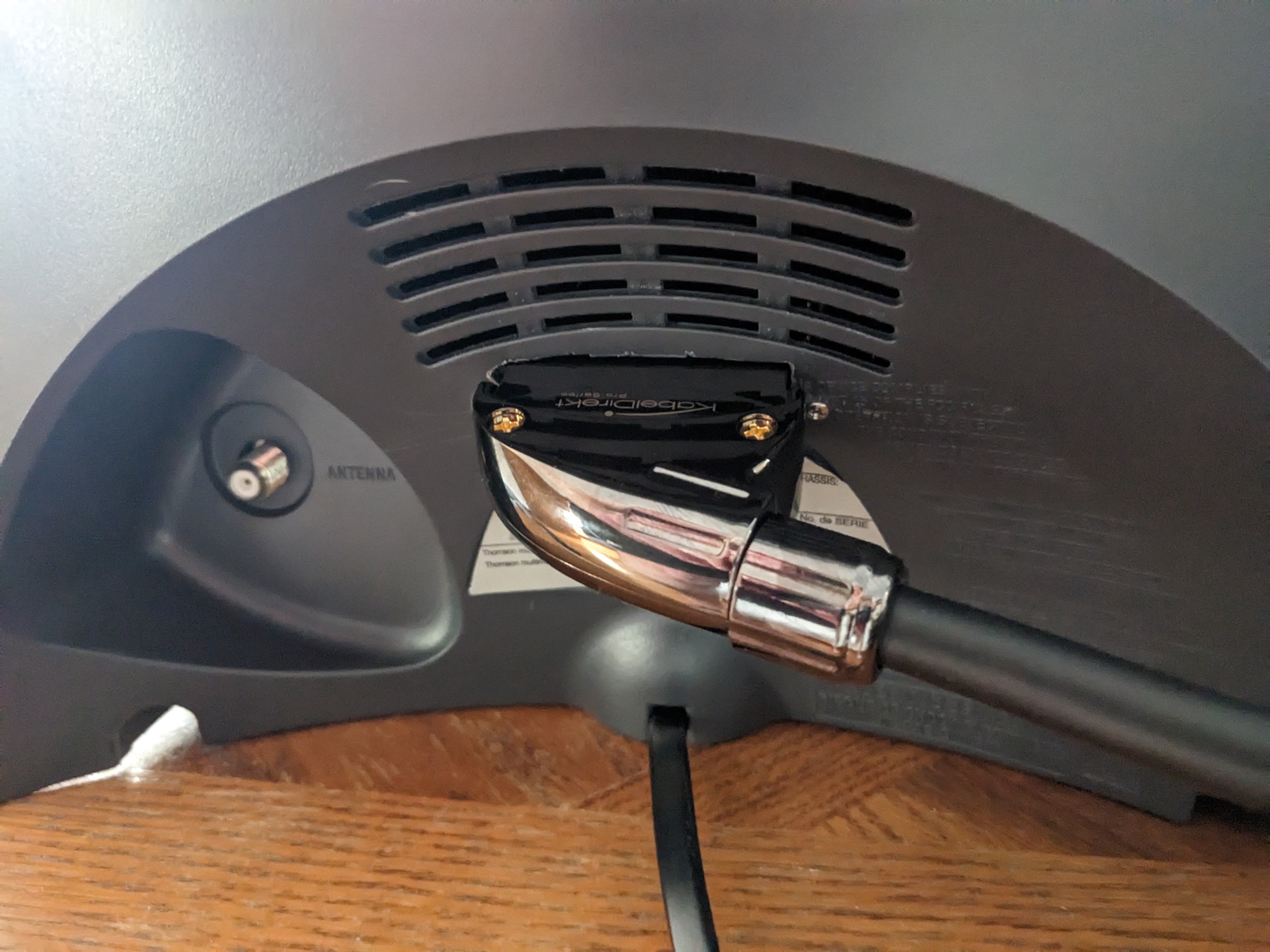
How to create and mount a SCART female plug?
STEP 8: Service Menu Adjustments
Get into the service menu by following the instructions on Service Manual.
With the CRT "ON" press and hold the "VOL - " button and then in sequence press and release the "CH +" button and the "CH -" button.
Then, press and hold VOL + button until you see 076. 000000 should be set to 076.
Once there, use CH + and CH - button to choose the correct parameter.
09 is the Horizontal phase parameter.
Update the value using VOL - or VOL + buttons.
When values are changed they are automatically written to memory. Just power off and power on to exit the service menu and get back to normal operation.
| Name | Value | |
|---|---|---|
| 0 | Security # | 76 |
| 1 | VCO | 93 |
| 2 | AGC | 32 |
| 3 | Red Bias | 106 |
| 4 | Green Bias | 113 |
| 5 | Blue Bias | 52 |
| 6 | Green Drive | 112 |
| 7 | Blue Drive | 123 |
| 8 | Peak White | 33 |
| 9 | Horizontal Phase | 26 |
| 10 | Vertical Amplitude | 35 |
| 11 | Vertical Phase | 6 |
Sunthar's Pictures
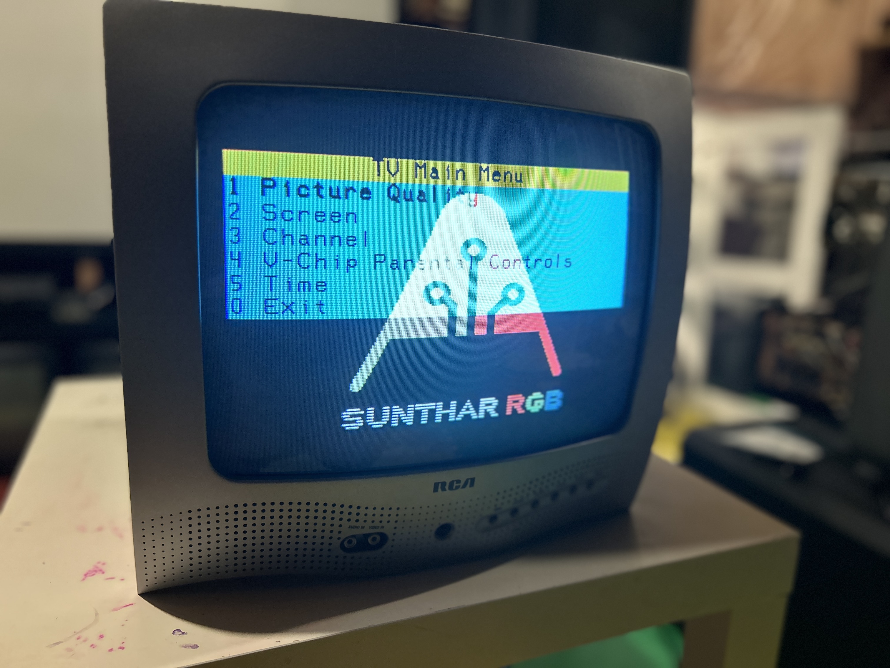
OSD overlay on top of RGB
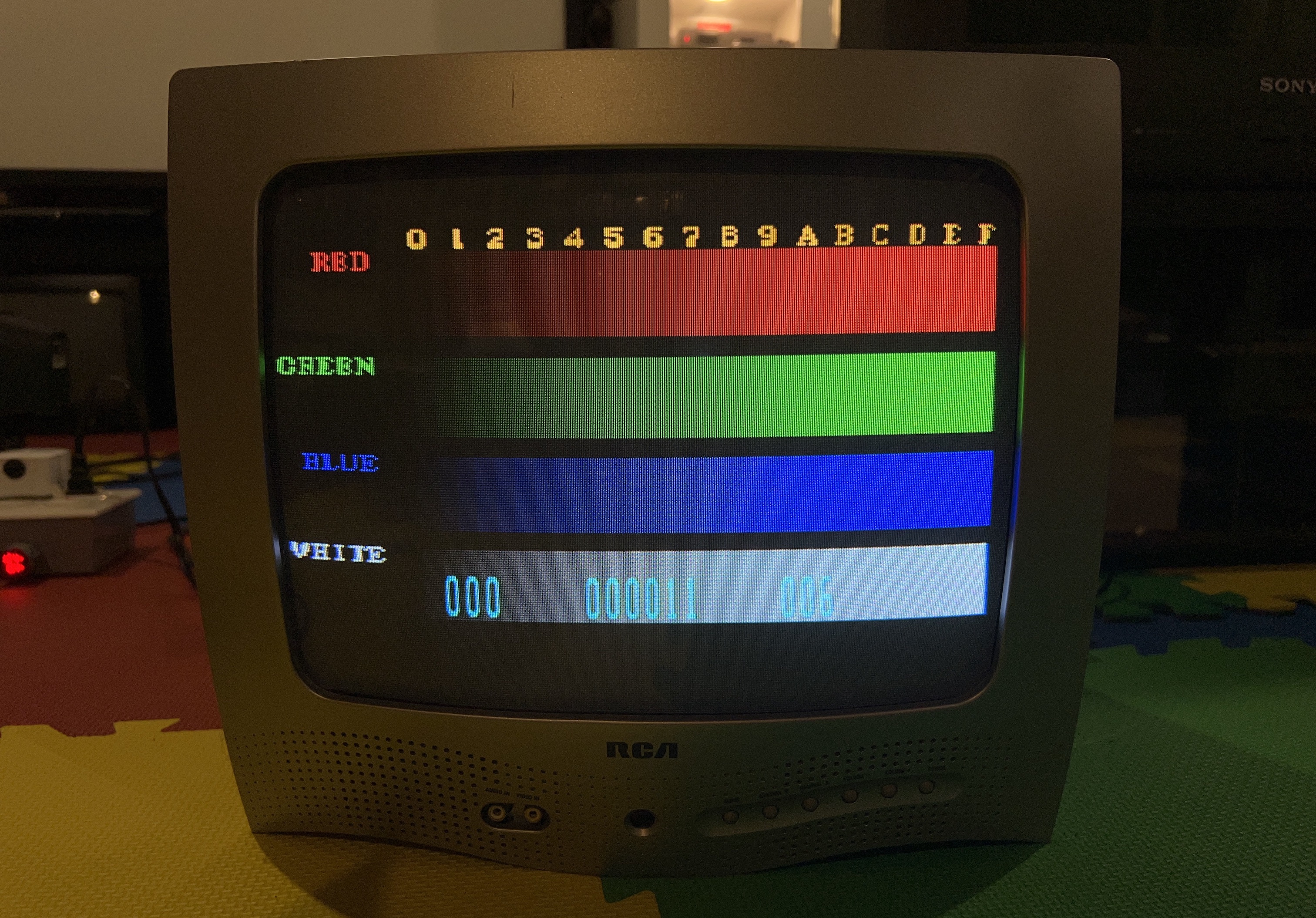
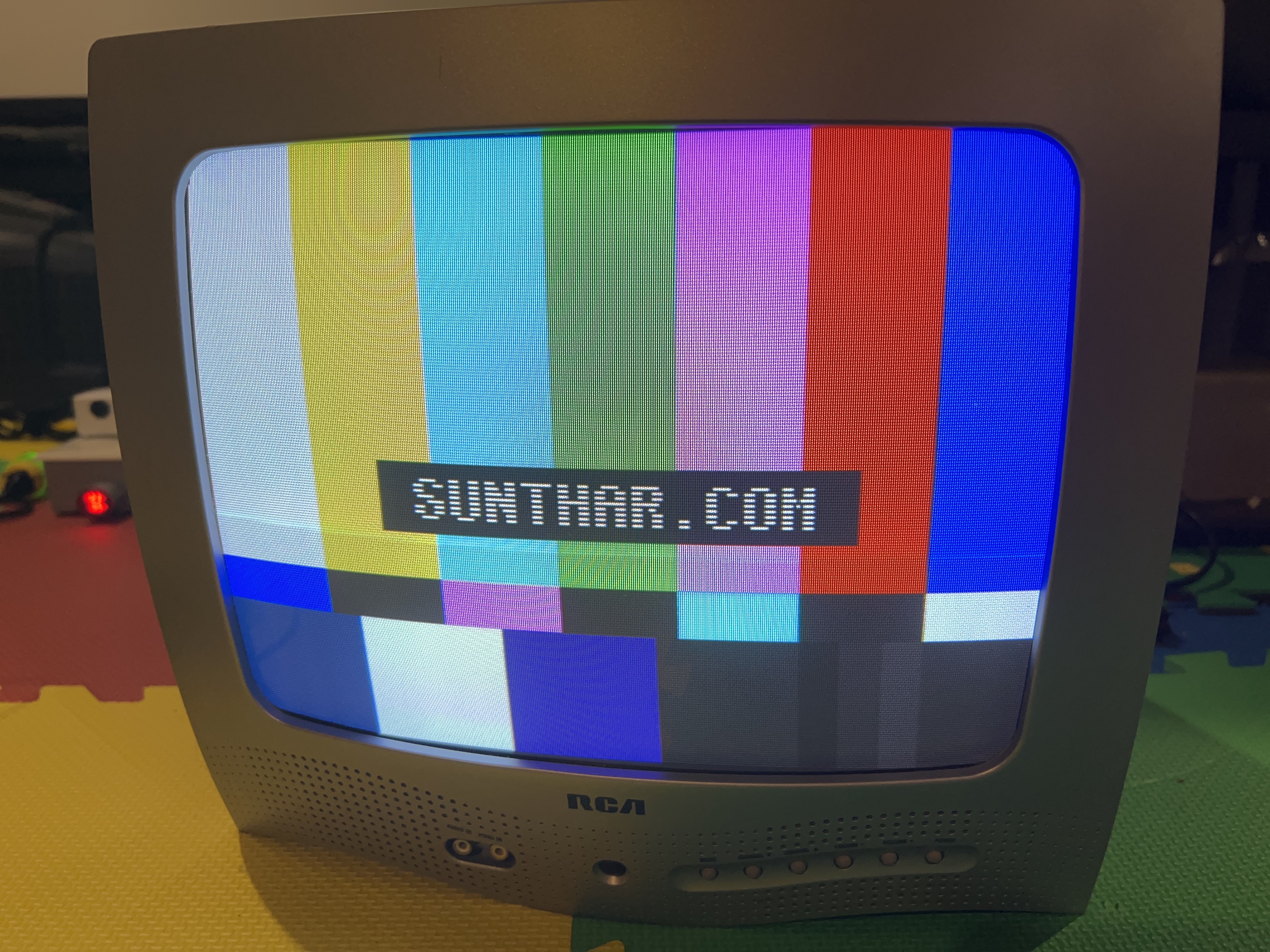
Color bars and SMPTE
After slightly turning up the flyback SCREEN voltage and tweaking the Bias and Drive values on service menu, a good color balance should be reached.
Below images were taken from SNES outputting 240p test suite. You want the RGB colors and the SMPTE patterns to look like the below.
Martin's Pictures

Pictures
Photos by Sunthar's Super Store
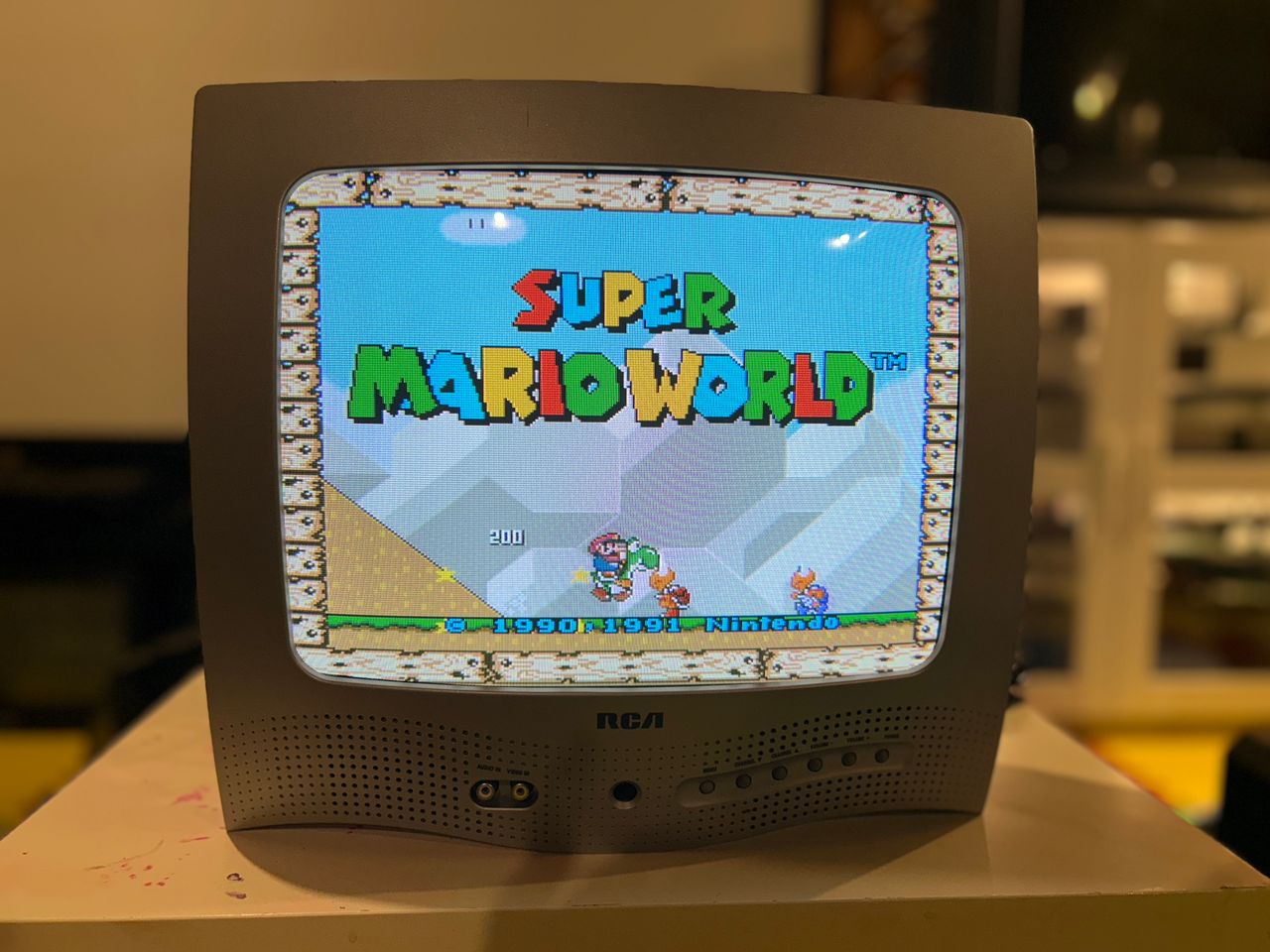
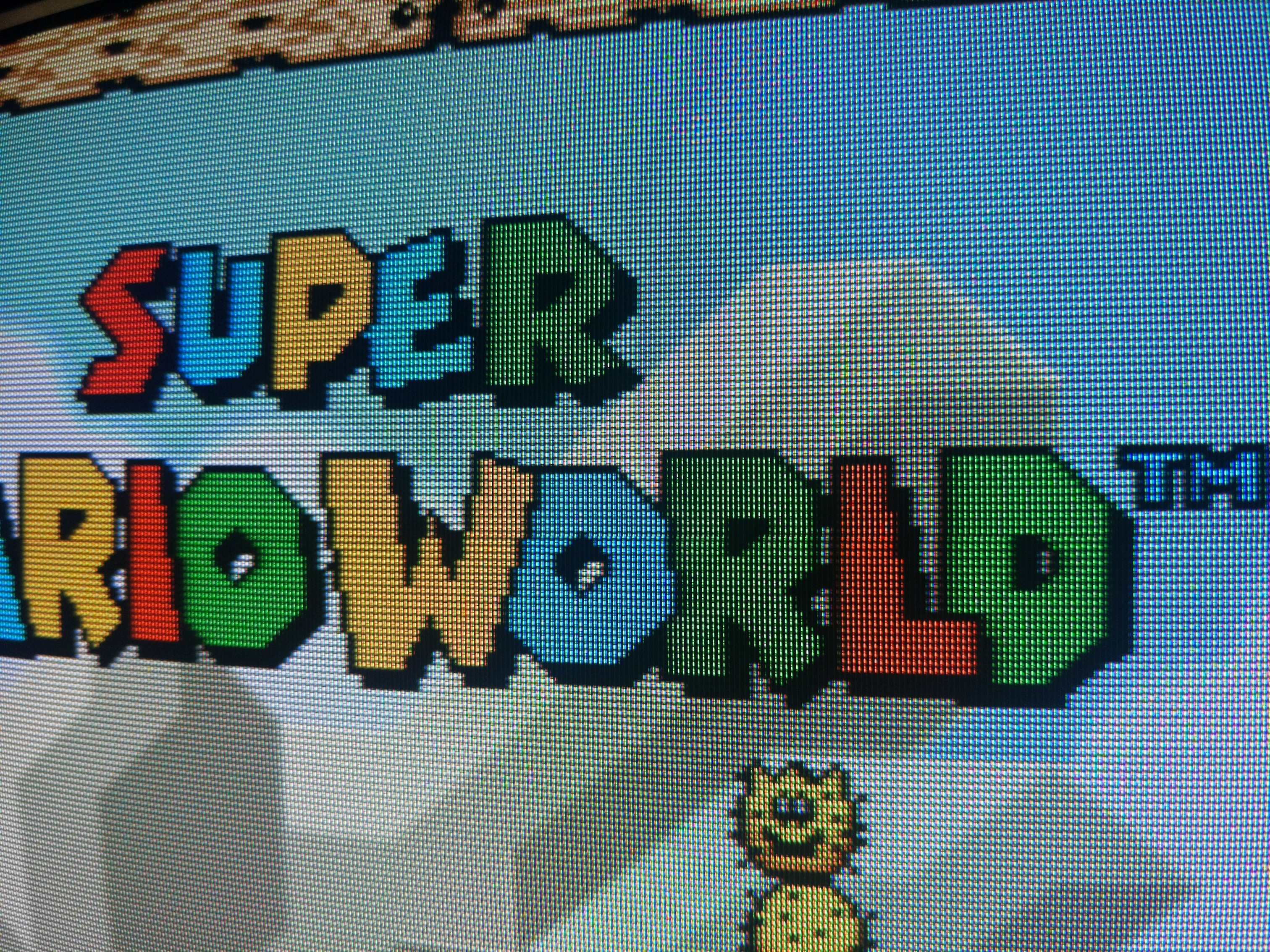
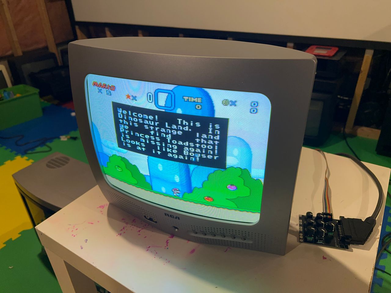
SNES - Super Mario World
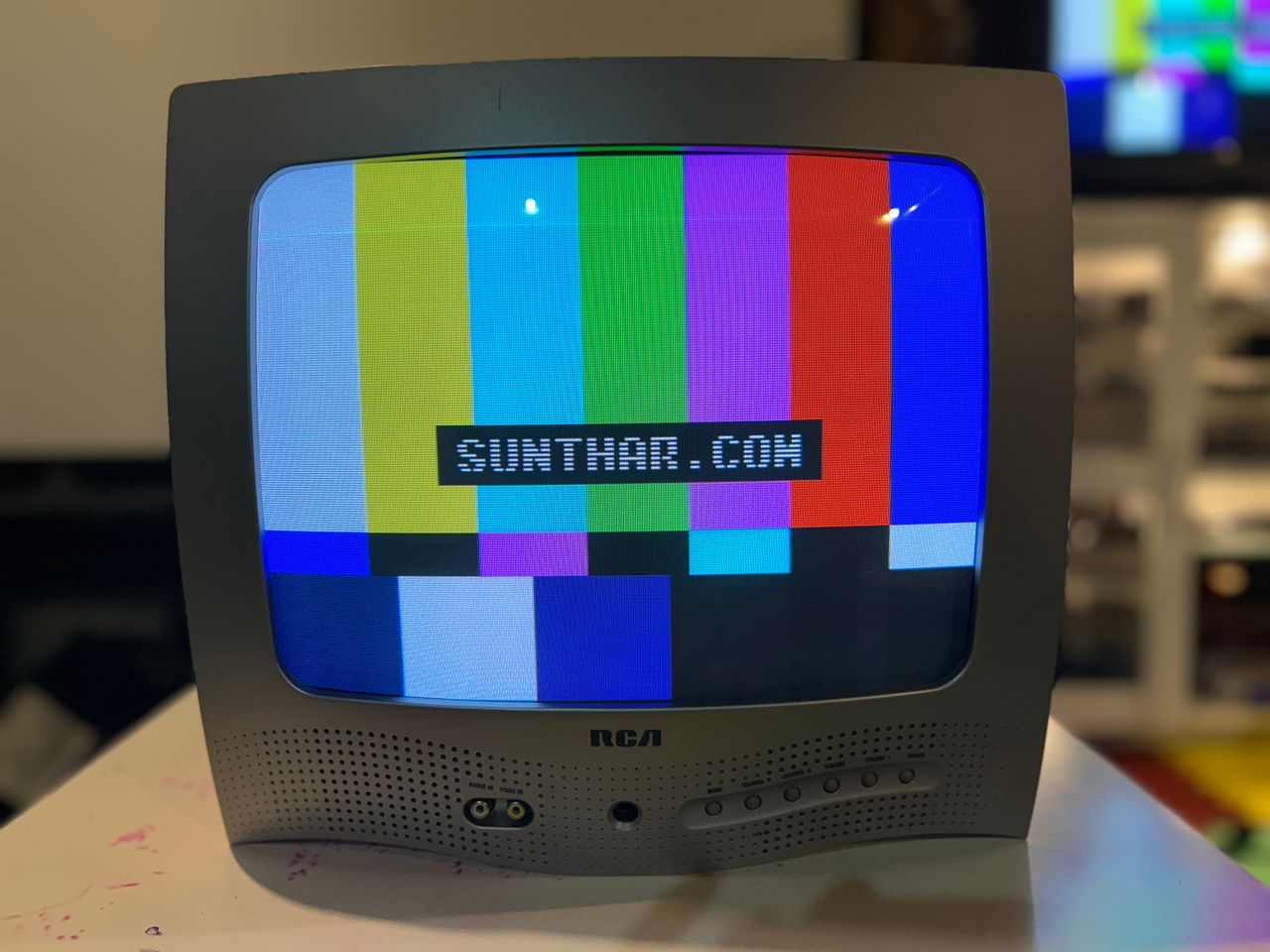
SMPTE Sunthar Pattern
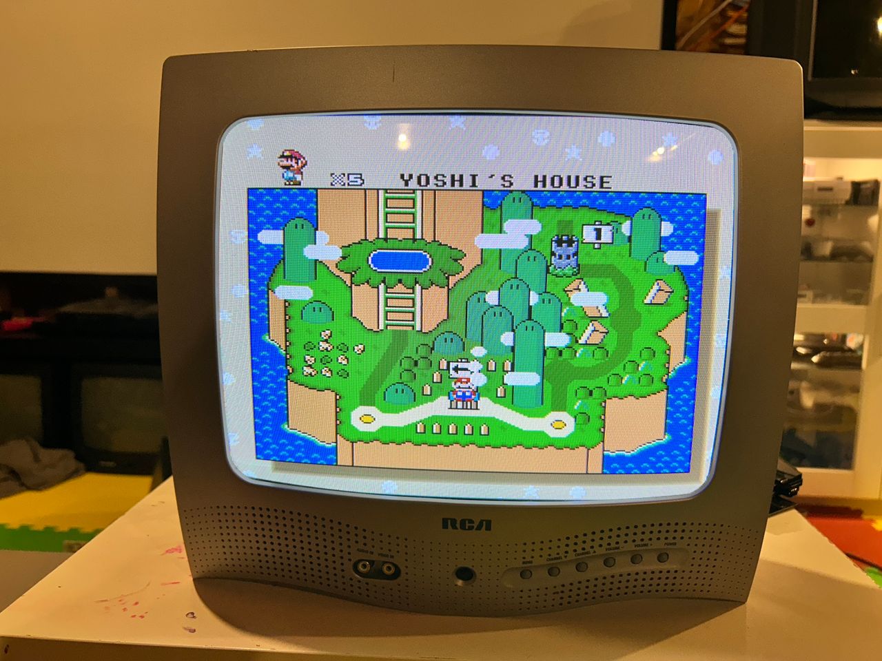
SNES - Super Mario World
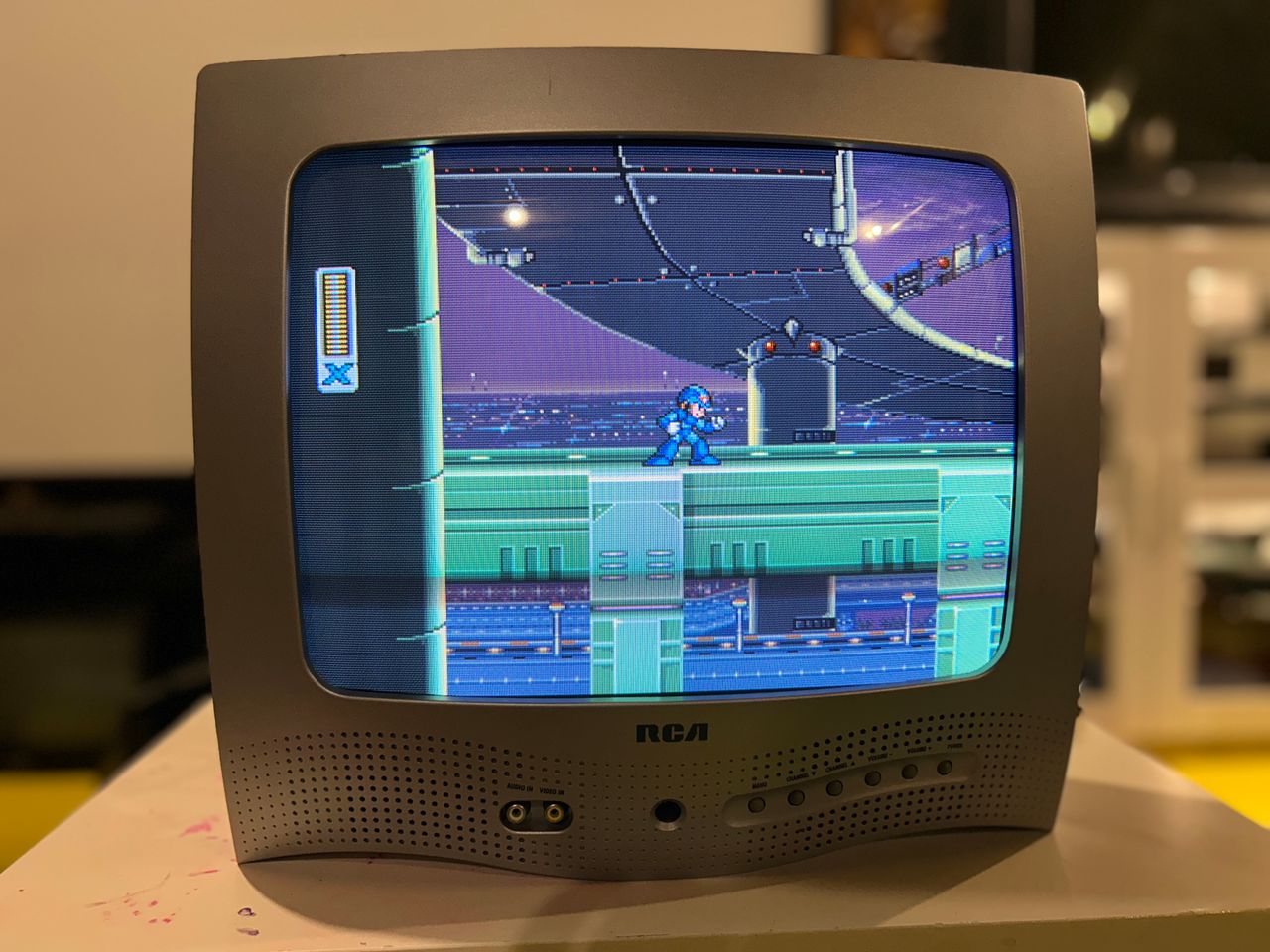
SNES - Megaman X
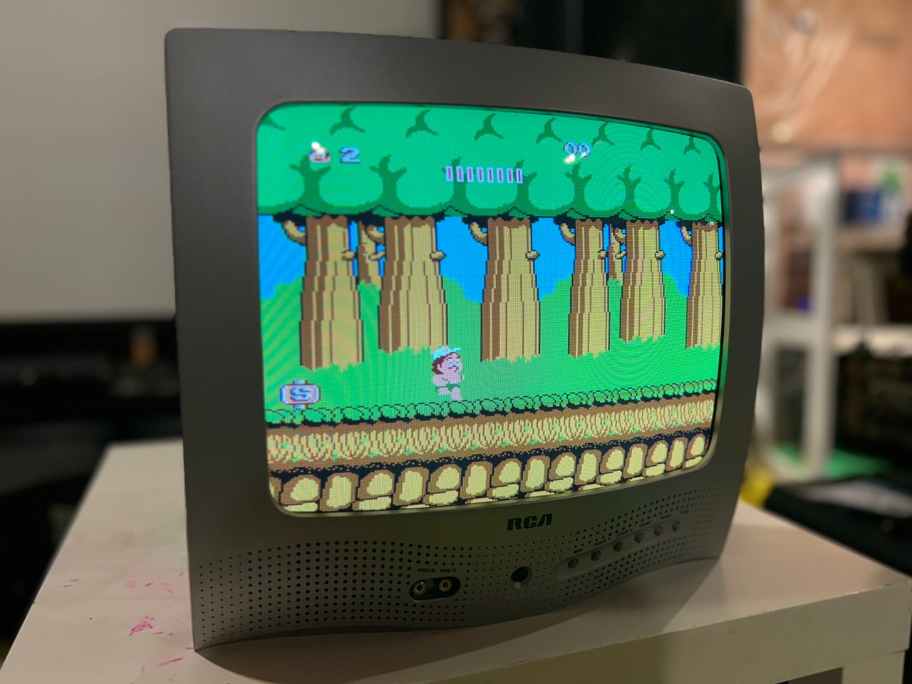
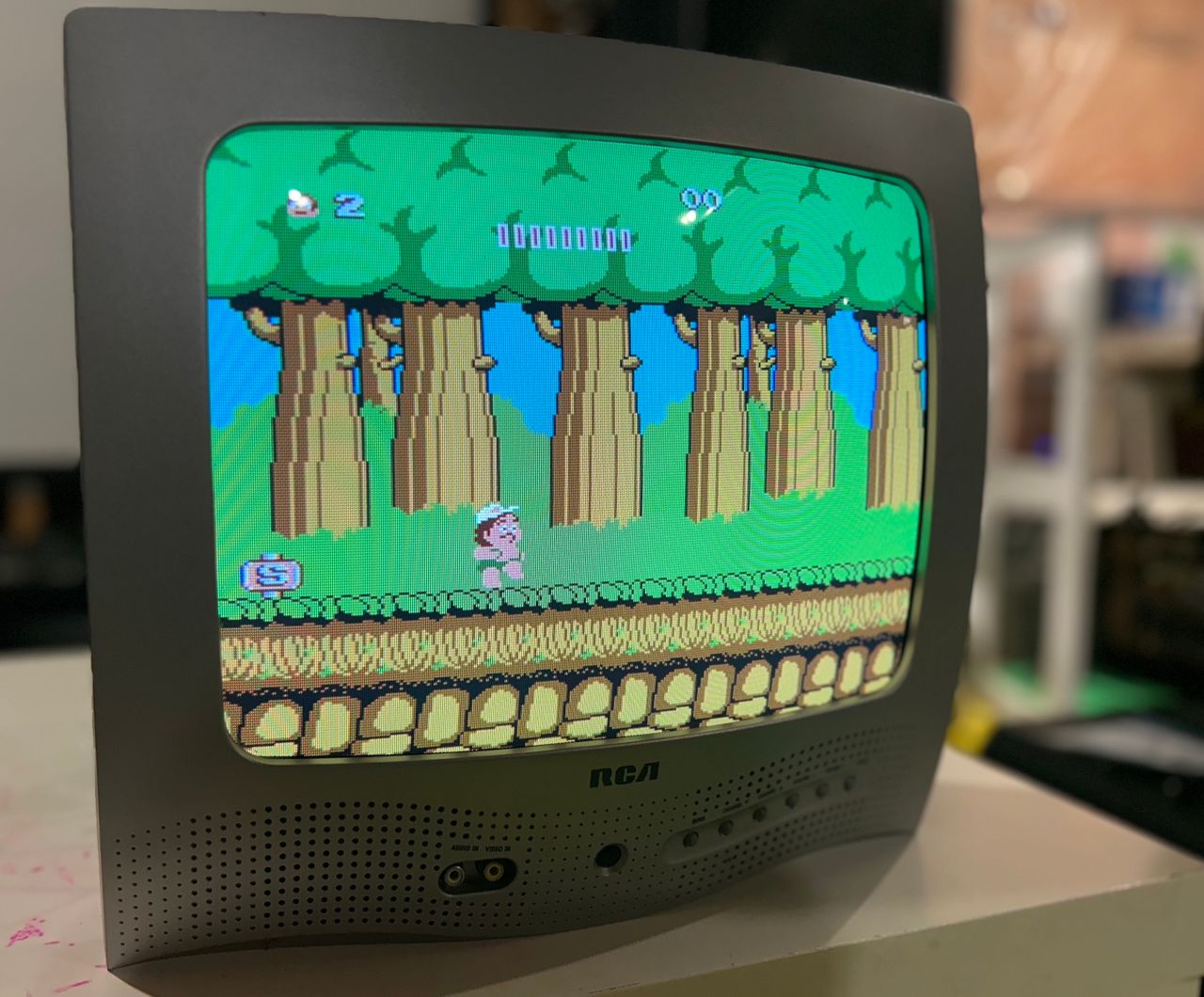
NES - Adventure Island

Photos by Robert McCoy's Sector
Reference Photos
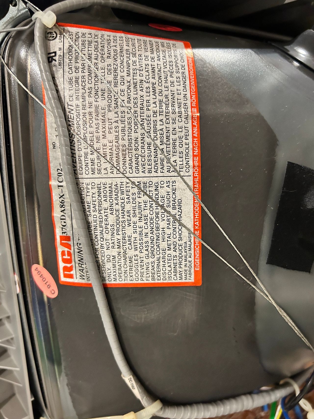
Tube picture
Back label
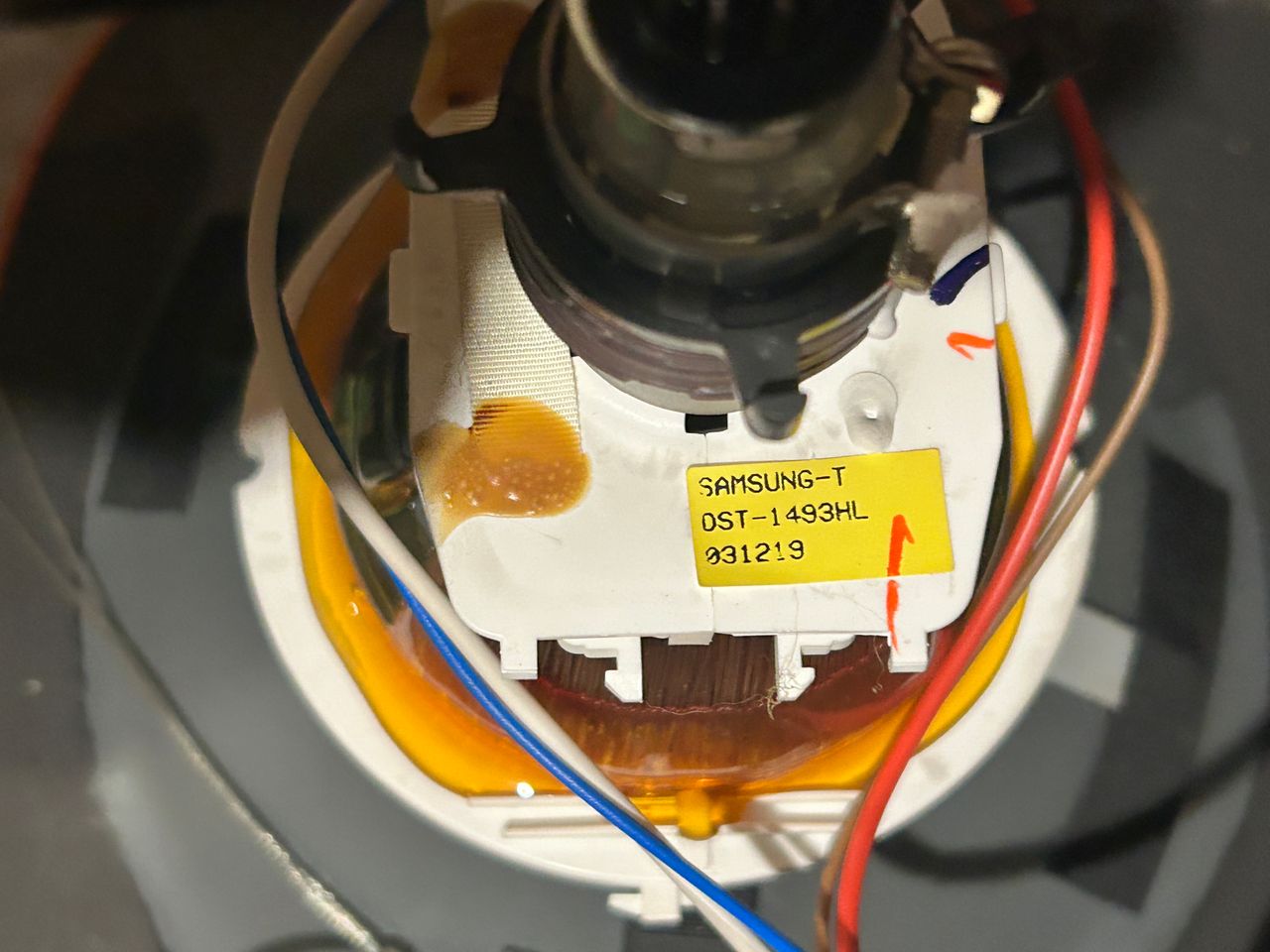
Yoke
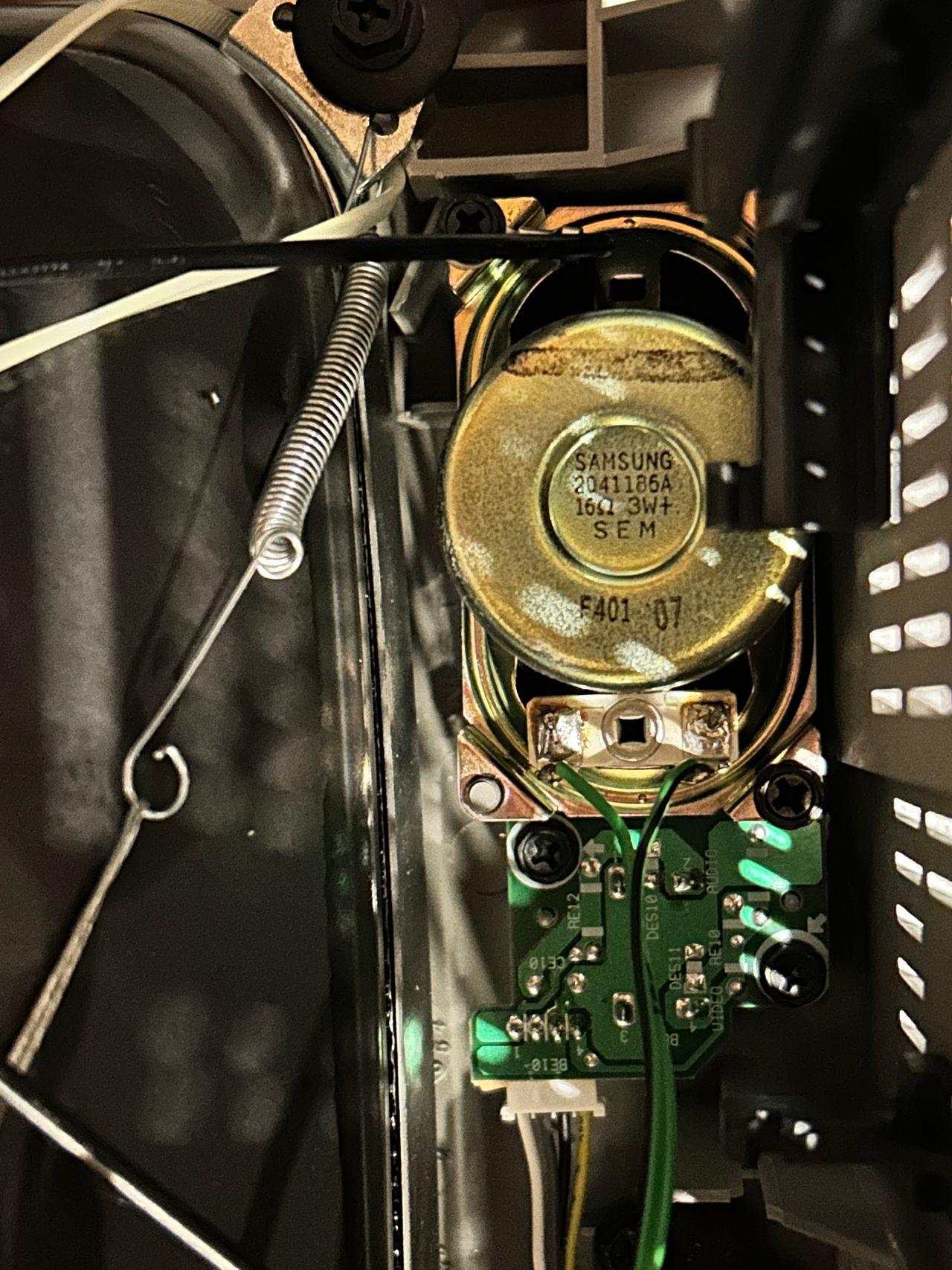
Speakers