Toshiba 14AF43+
Toshiba 14AF43+ CRT RGB mod
The Toshiba 14AF43 is a 14" flat CRT television known for its premium features in a compact, bookshelf-friendly size. Although it carries the Toshiba brand, it is built around an Orion picture tube. The television includes RF, Composite, S-Video, and Component (YPbPr) inputs and can also be modified for RGB input.
View full CRT details and more mod examples →
This tutorial covers the RGB mod for the below models
- Toshiba 14AF43
- Toshiba 14AF44
- Toshiba 14AF45
- Toshiba 14AF46
Table of Contents
Contributors
Thank you to everyone who contributed to this guide:
- Sunthar — contributor, RGB mod and pictures
CRT safety
Caution
You can die doing this! So read carefully! CRT TV is not a toy. Do not open a CRT TV. If you don't have any prior knowledge about handling high voltage devices, this guide is not for you. CRT TV contains high enough voltage (20,000+ V) and current to be deadly, even when it is turned off.
Plan of attack
Manuals and Datasheets
- Toshiba 14AF43 Service Manual
- Toshiba 14AF43 Service Manual
- Toshiba 14AF43 Service Manual
- Toshiba 14AF43 Service Manual
- Renesas M61283FP Datasheet (Jungle)
Specs
- Year: 2003
- Format: NTSC
- Chassis: M3M827
- Tube: Orion A36AKJ13X05
- Jungle Chip: Renesas M61283FP
- OSD Chip: Orion OEC7090A
- Screen Size: 14"
- Power: 80 W
- Weight: 24.3 lbs
- Inputs: Composite, S-Video, RF, Component YPbPr
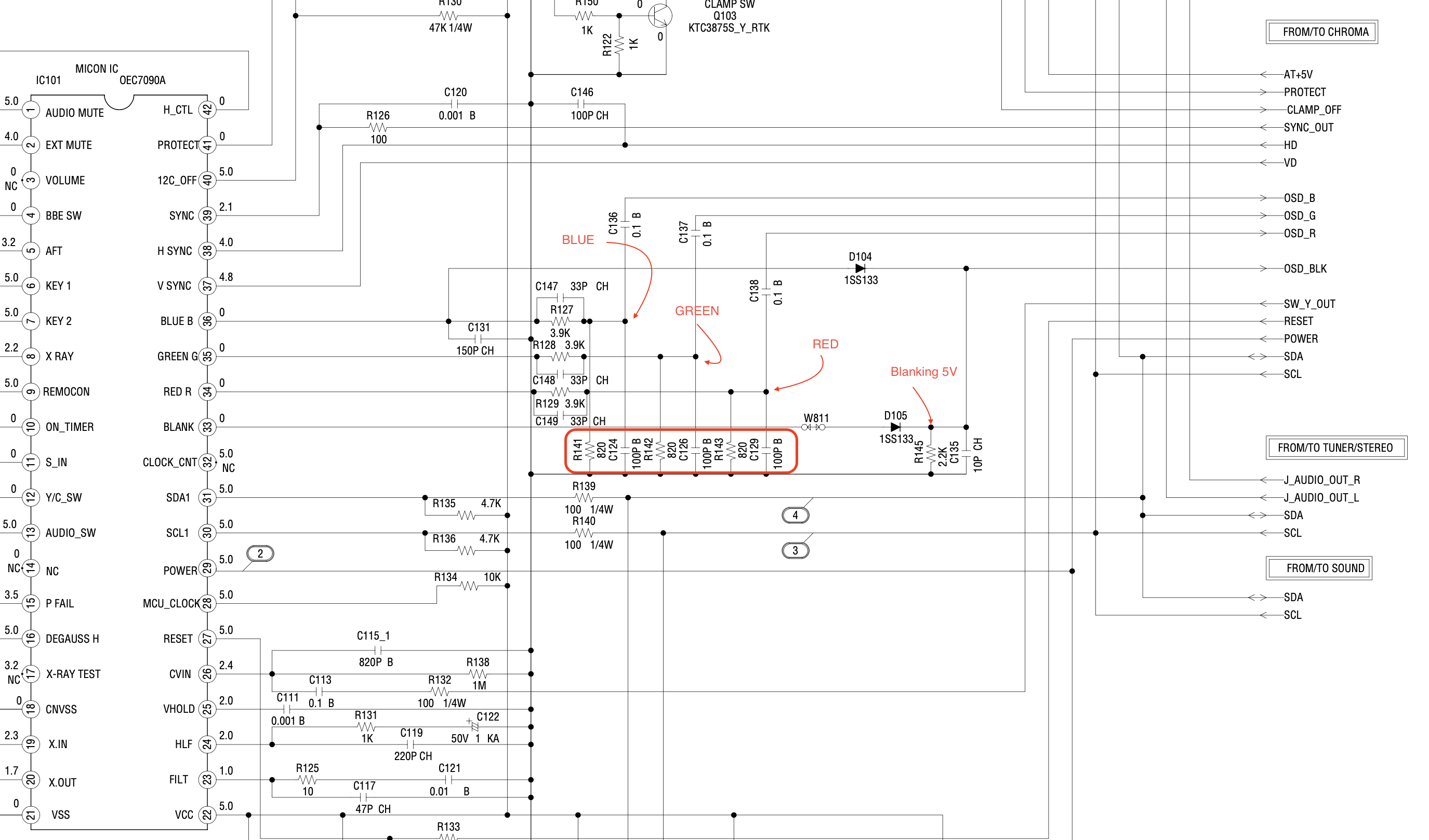
Schematics
Get hold of the schematics for your TV. Understand where the RGB and Fast Blanking signals go from OSD to the Jungle (Chroma) chip.
14AF43
14AF44
Below schematics is similar to 20AF44 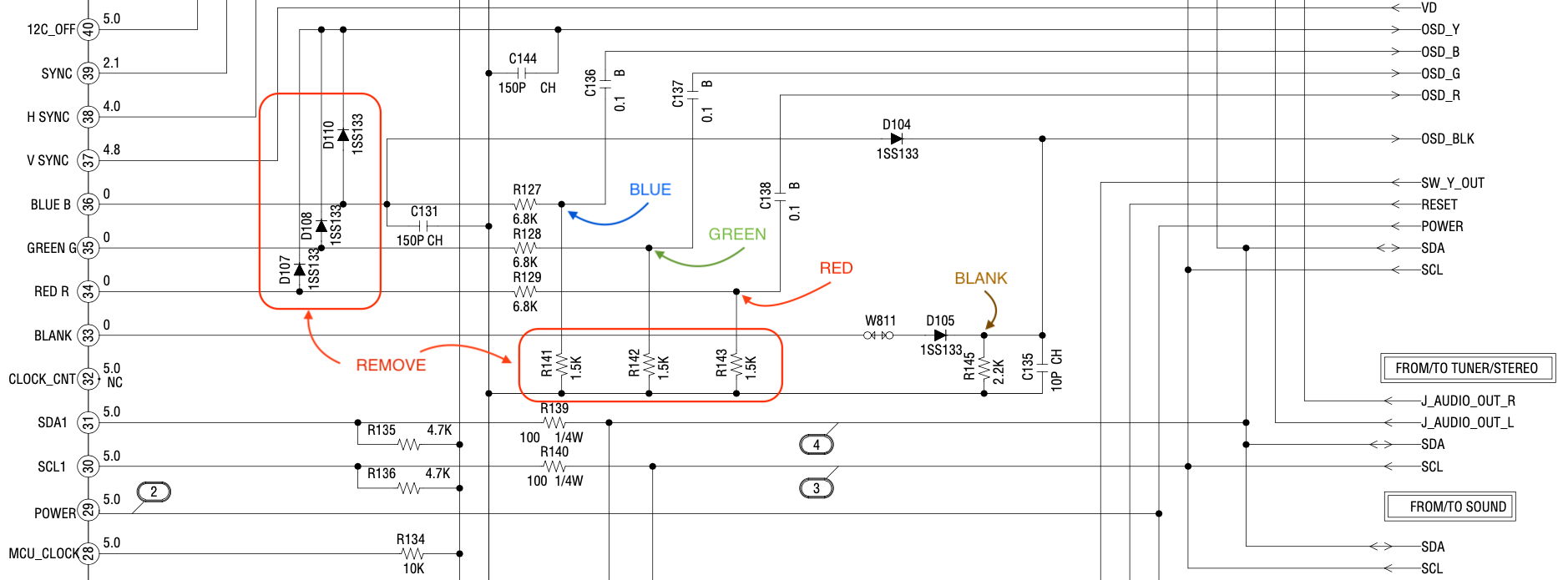
RGB mux diagram
Prepare the mux diagram. If you are building your own circuit, this diagram should help.
Performing the mod
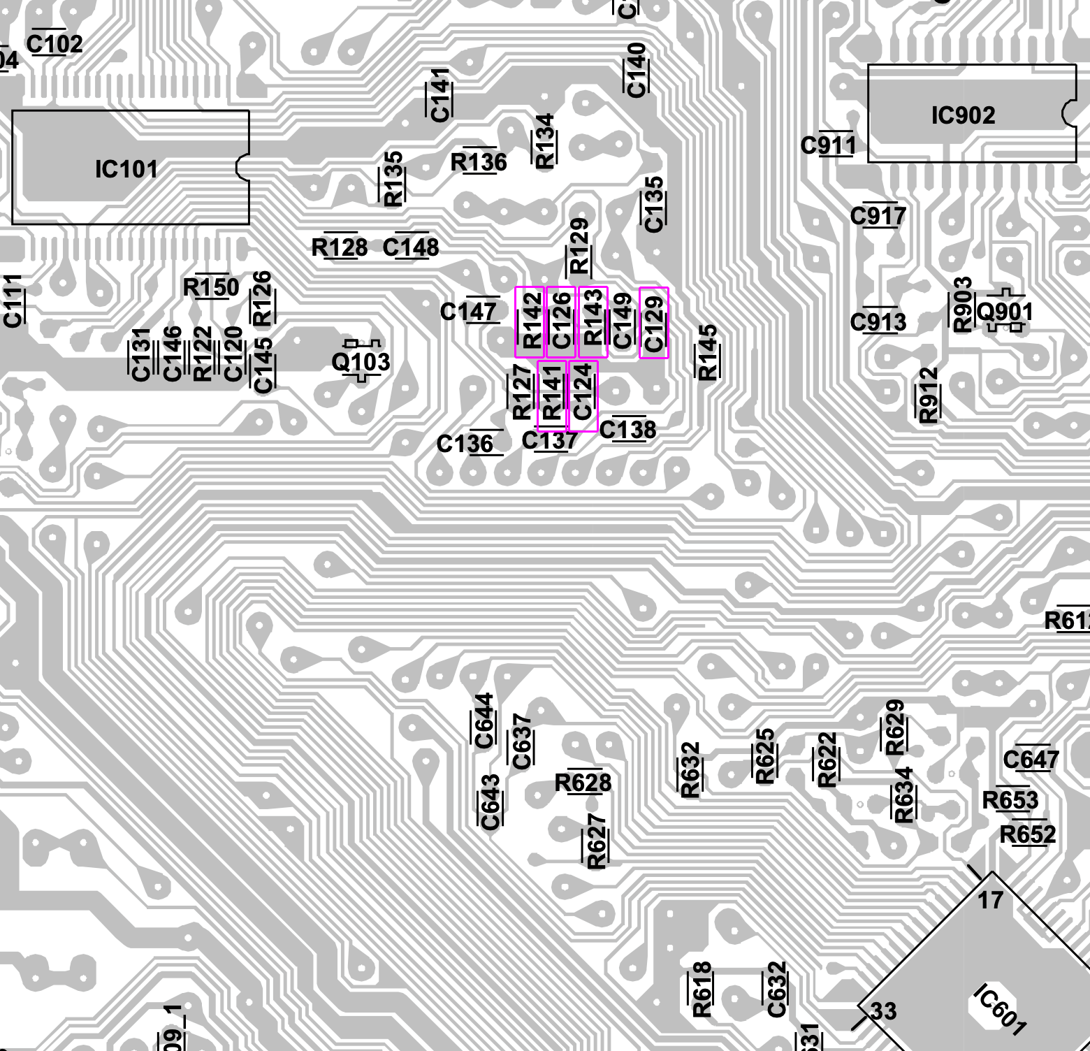
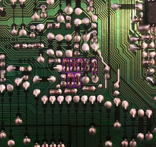
STEP 1: Remove the following components
14AF43
- Remove the following components
RGB resistors to the ground
- R141
- R142
- R143
Coupling capacitors to the ground
- C124
- C126
- C129
Warning
I also removed C131. This impacted the OSD blue background. Lesson learned. Don't remove it.
14AF44
- 14AF44 is similar to 14AF43. Remove the following components
RGB resistors to ground
- R141
- R142
- R143
There were no coupling capacitors to the ground that needed to be removed on my particular system. However, if you do find them in your TV, please remove them. Sometimes these coupling capacitors are mentioned in the service manual, but you don't find them on the actual board and vice-versa.
Coupling capacitors to ground
- C124
- C126
- C129
Did not remove C131 or C135. Removing them can affect the background of the OSD. Therefore, left them alone.
STEP 2: Connect RGBs, Blanking and Audio
14AF43/14AF44
Connect the R, G, B and blanking (orange) wire. "X" is where the wires are connected. 
The mod on the board itself 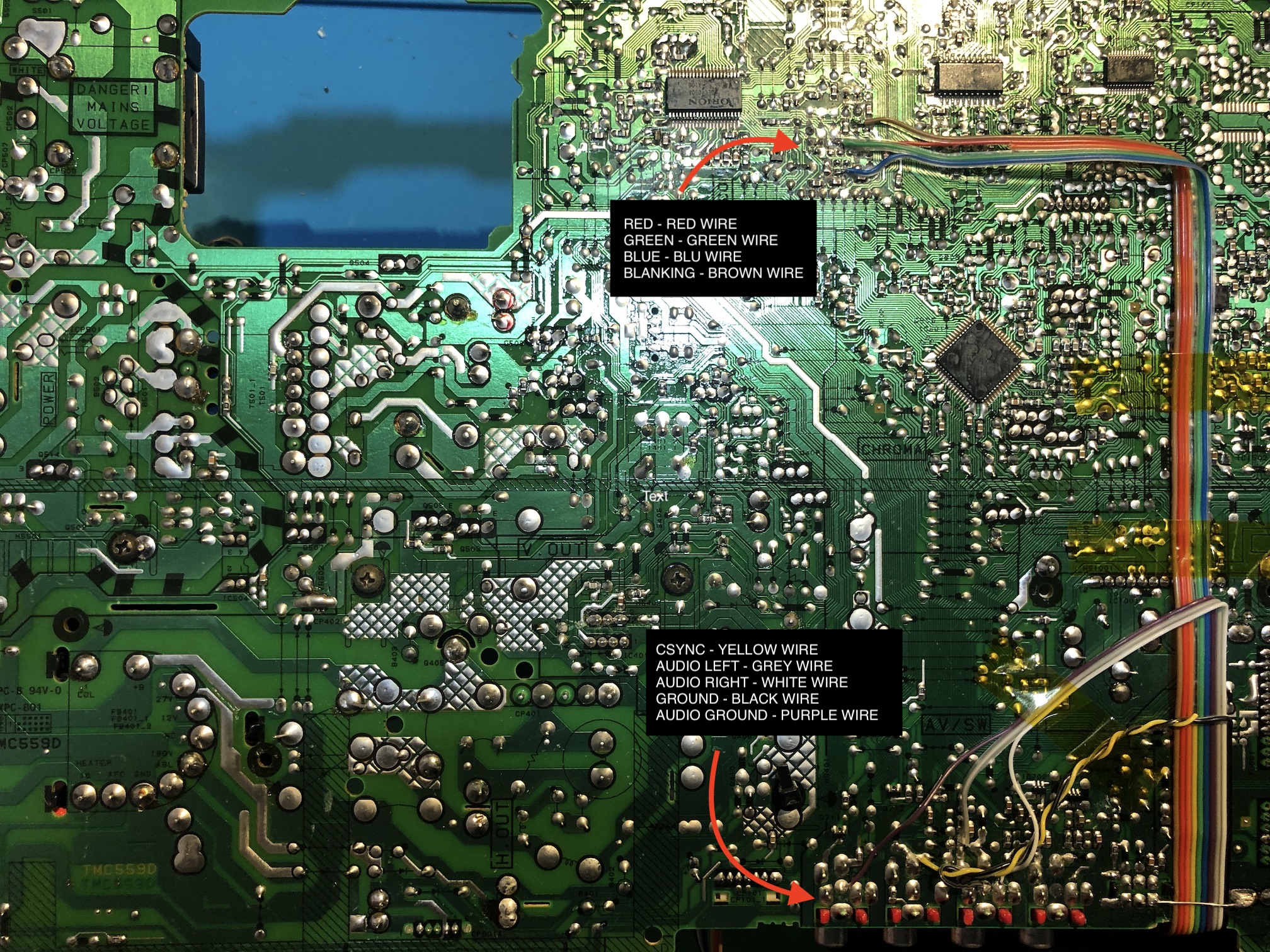
Close up of RGB and Blanking 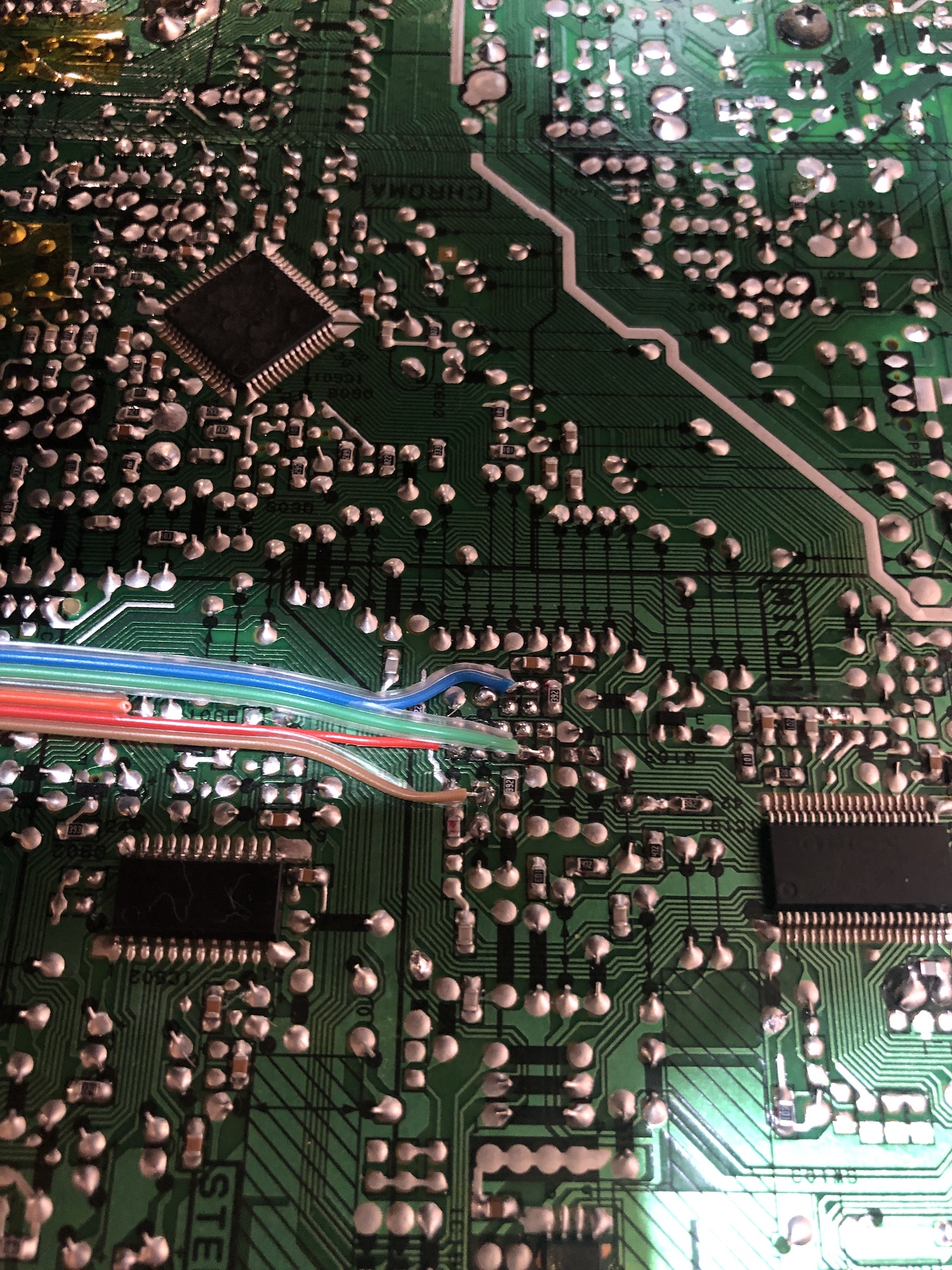
Close up of Sync and Audio 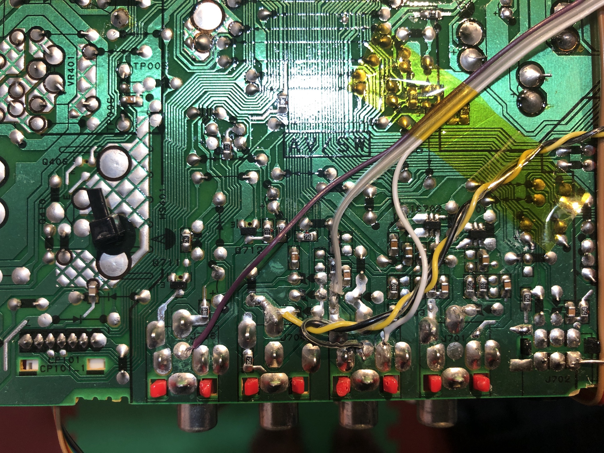
STEP 3: Build your mux circuit
This mod uses the RGB mux board. This is optional, but will make your mod easier and stable. You can also create the circuit presented in the schematics above without the board. Please also checkout the mux calculator to play with your own values.
| On Toshiba CRT Chassis | 14AF43 |
|---|---|
| CRT RGB inline resistor | 3.9kΩ |
| CRT RGB ground resistors removed | 680Ω |
| 0.1μF caps replaced | Yes |
| Add diodes on chassis RGB lines? | Yes |
| Add blanking diode on chassis | No |
| RGB mux board | 14AF43 |
|---|---|
| Mux board RGB termination (R1, R2, R3) | 75Ω |
| Mux board RGB inline resistors (R4, R5, R6) | 1kΩ |
| Mux board Audio LR (R7, R8) | 1kΩ |
| Mux board blanking diode (R9) | 1N4148 |
| Mux board blanking ground resistor (R10) | open |
| Mux board blanking resistor (R11) | short |
Compatible mux boards:
I recommend going with the 1.4C or 1.5C along with the trim plate for a cleaner, more professional look.
RGB mux adapter setup 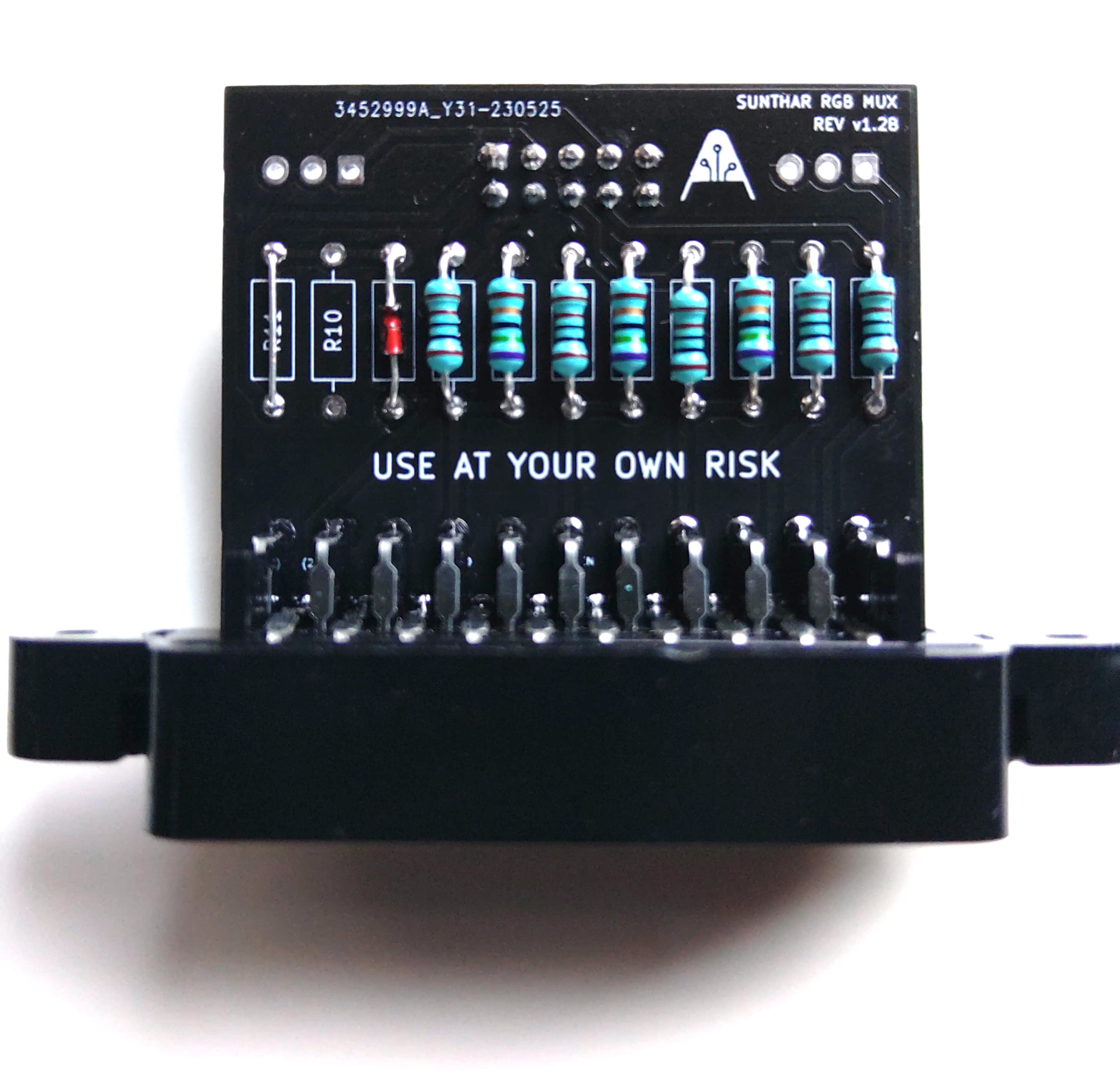
STEP 4: Attach the female SCART connector to TV
Creating a SCART cutout and mounting it is an art. I have a dedicated section for it.
How to create and mount a SCART female plug?
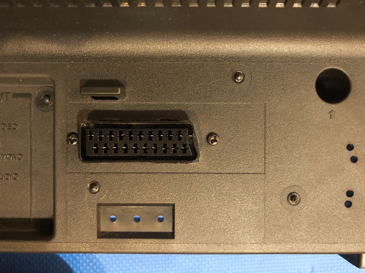
Finished mod
SCART connector inside a Toshiba 14AF43. This location was a bit closer to the flyback. However, there was very minimal to no interference noticed. 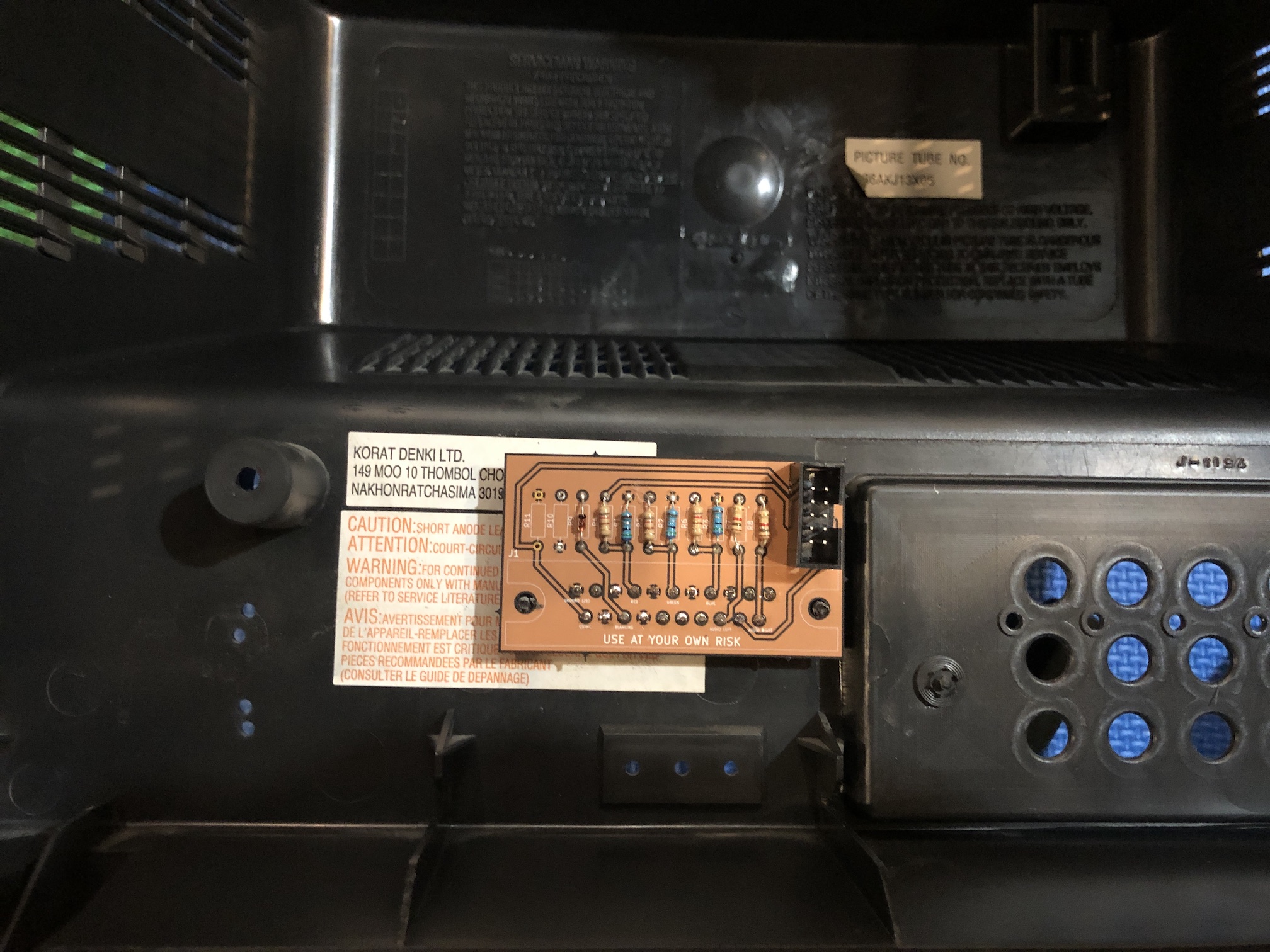
Not the best cutout for the SCART connector. But, it is straight and holds steady. 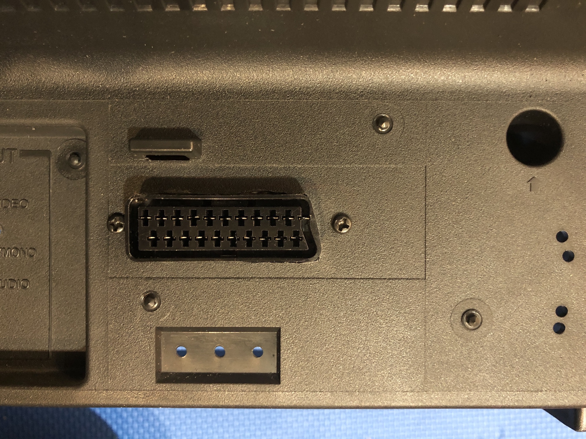
Full backside shot of 14AF43 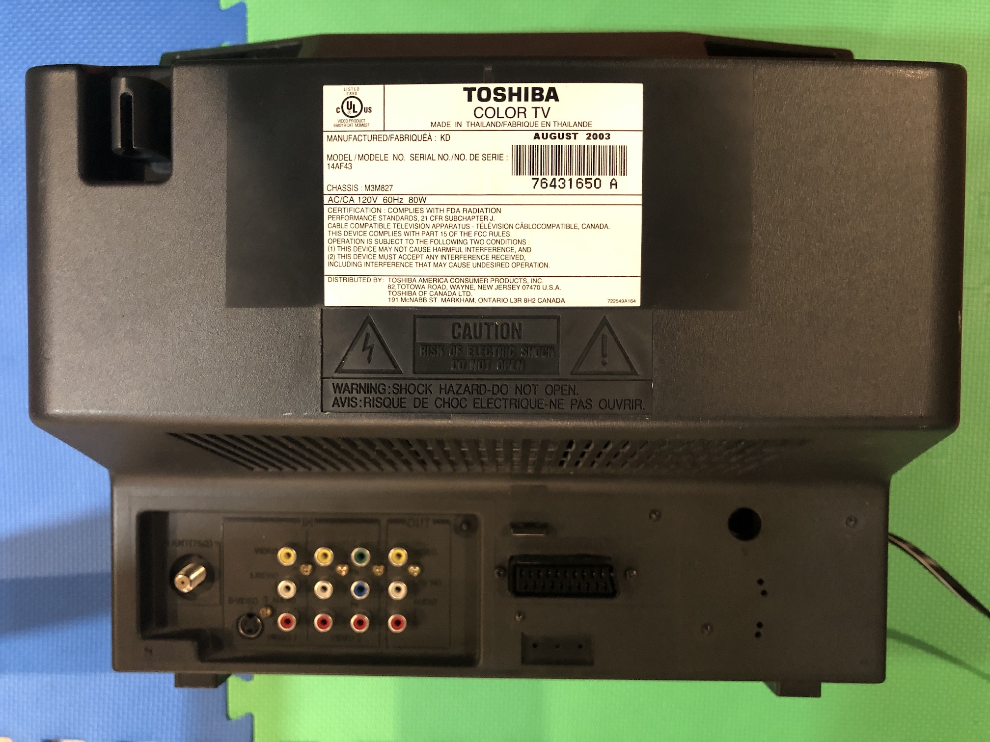
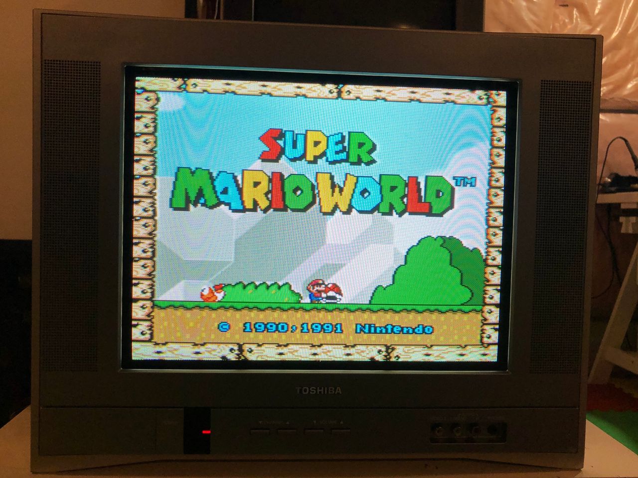
Games
These pictures don't justify the realworld experience. Nevertheless, good to see some!
Sonic - Sega Genesis 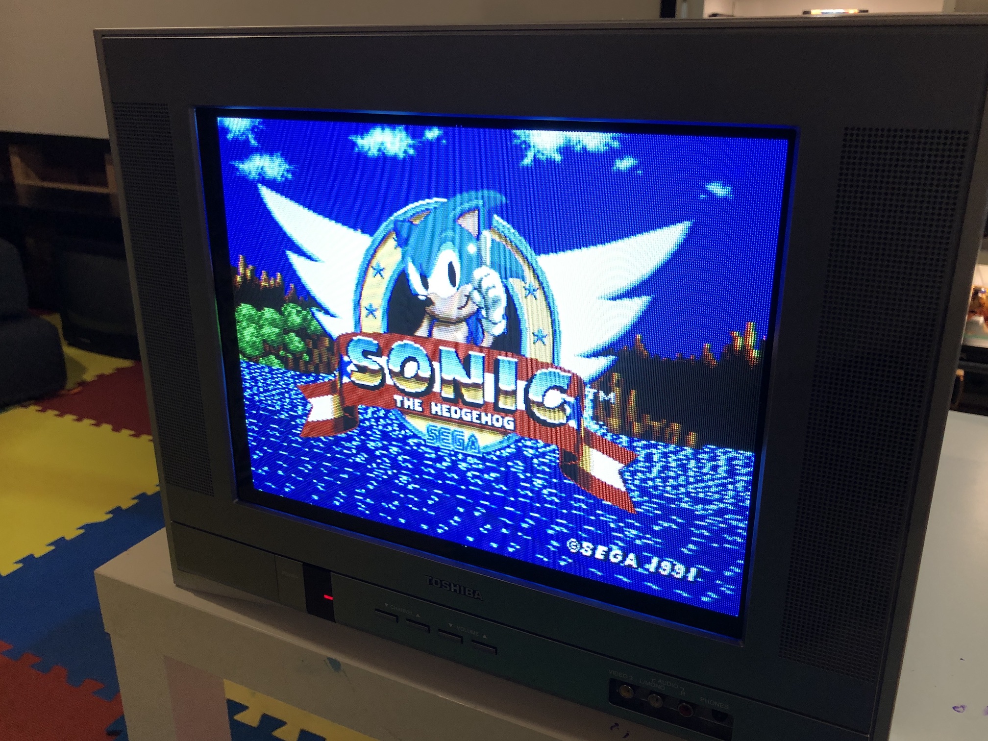
SNES - Super Mario World 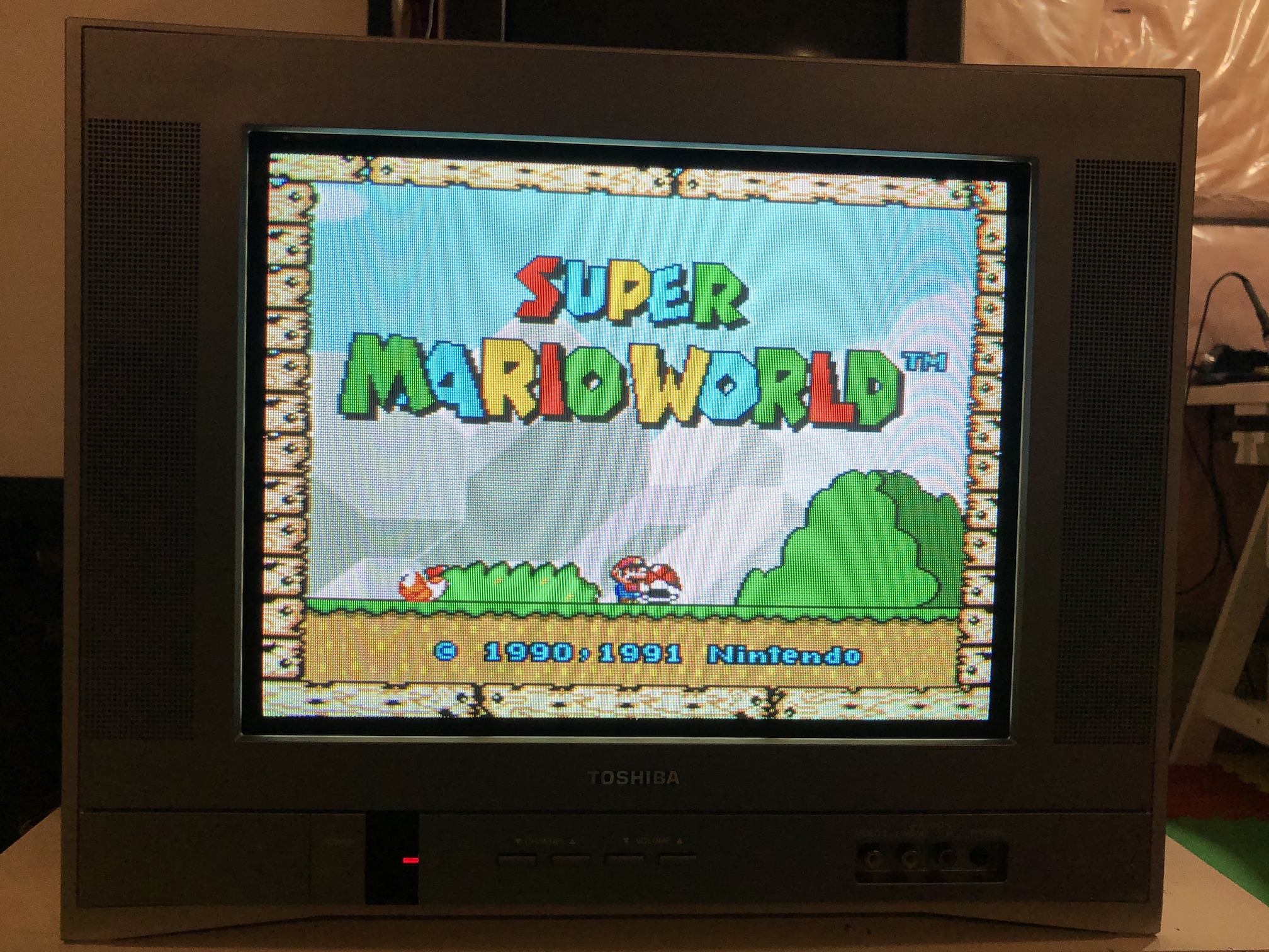
SNES - Megaman 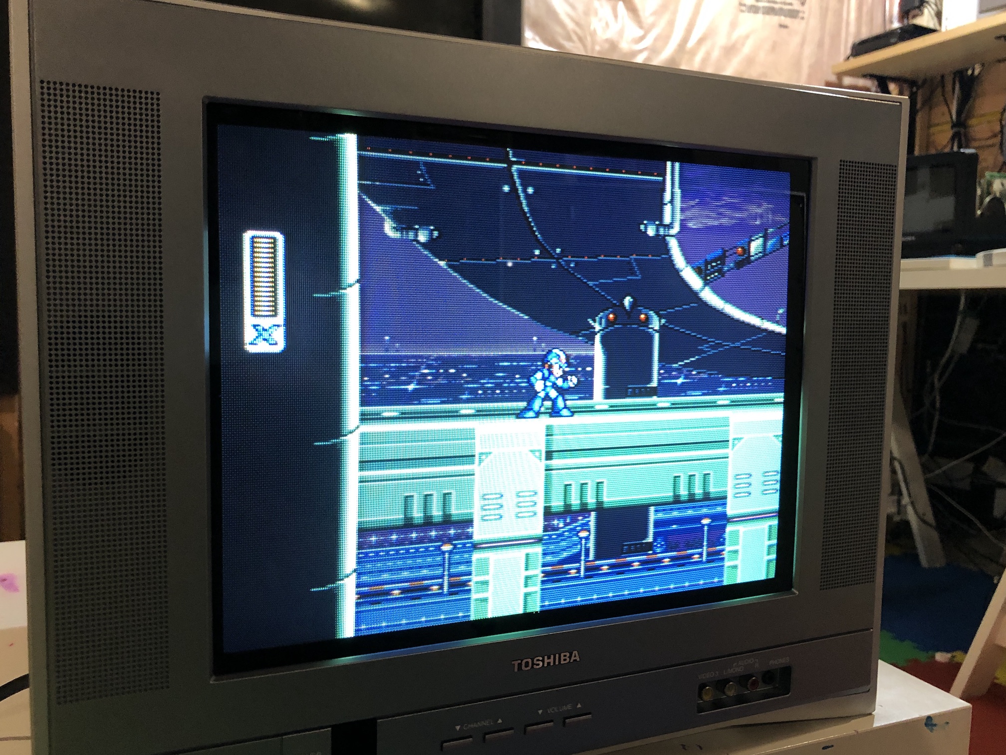
PS1 - Boot 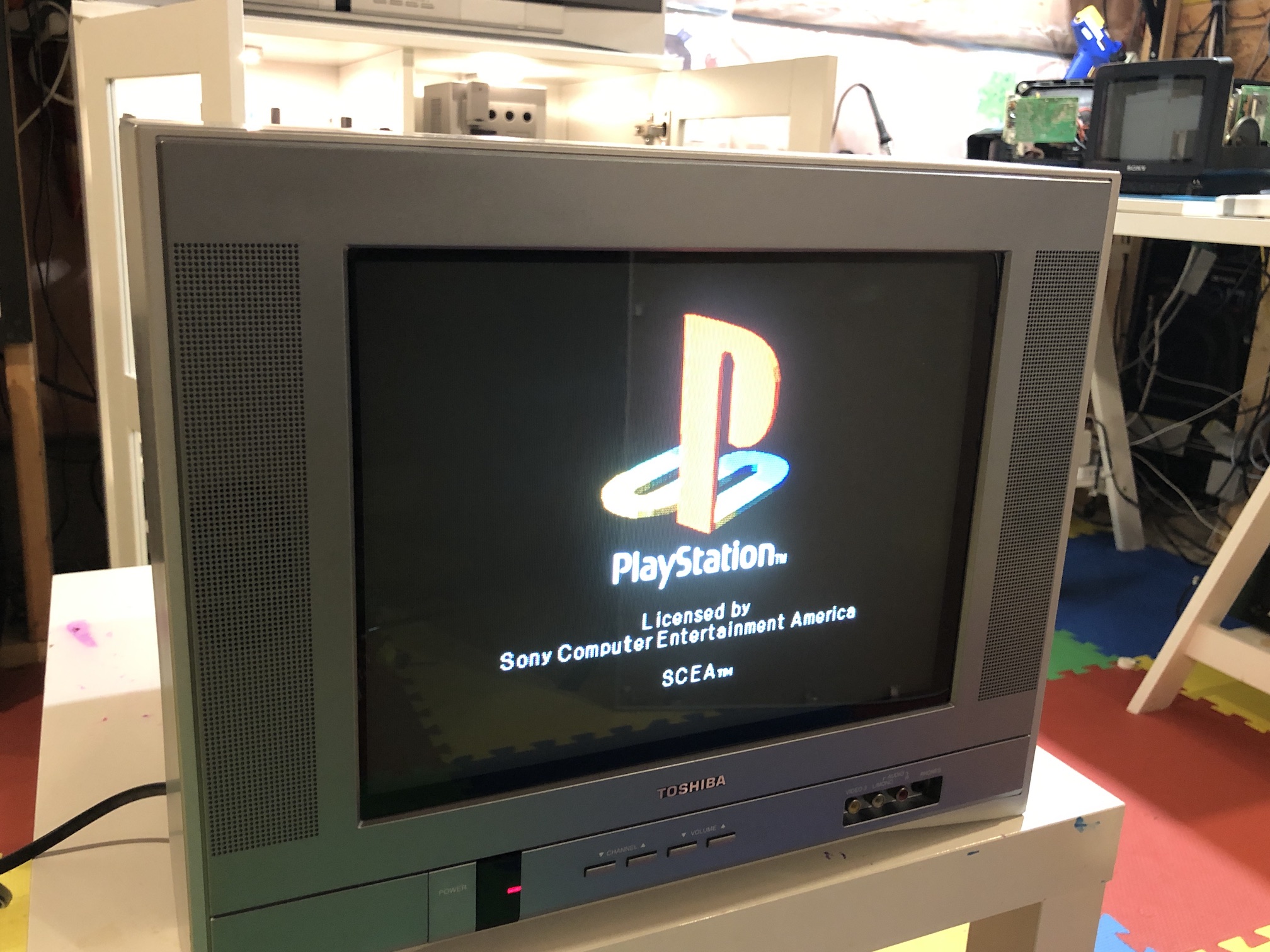
PS1 - Boot 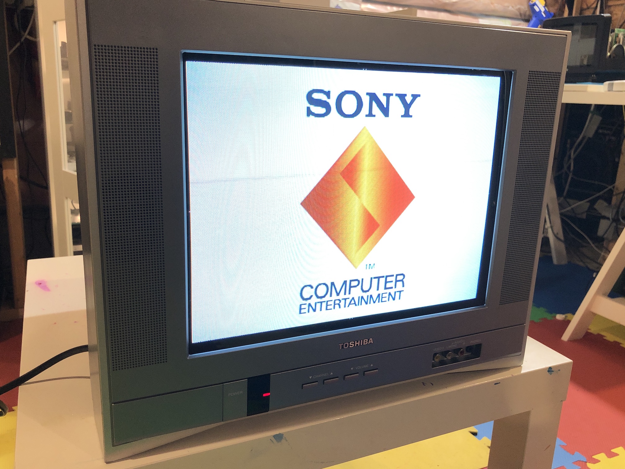
XBOX - Boot 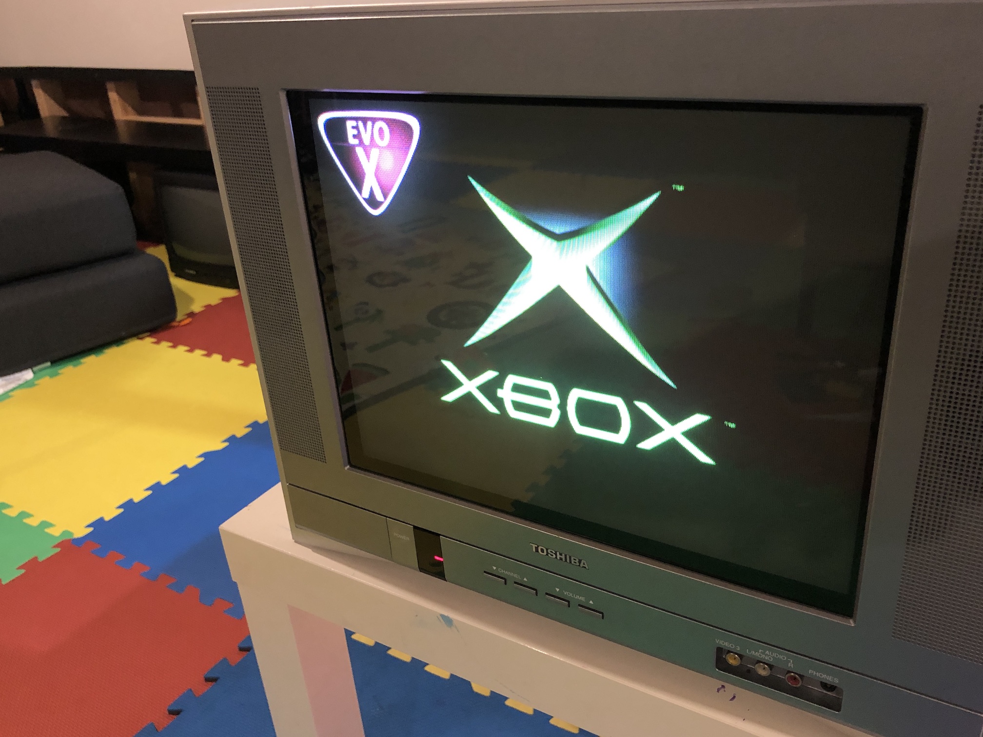
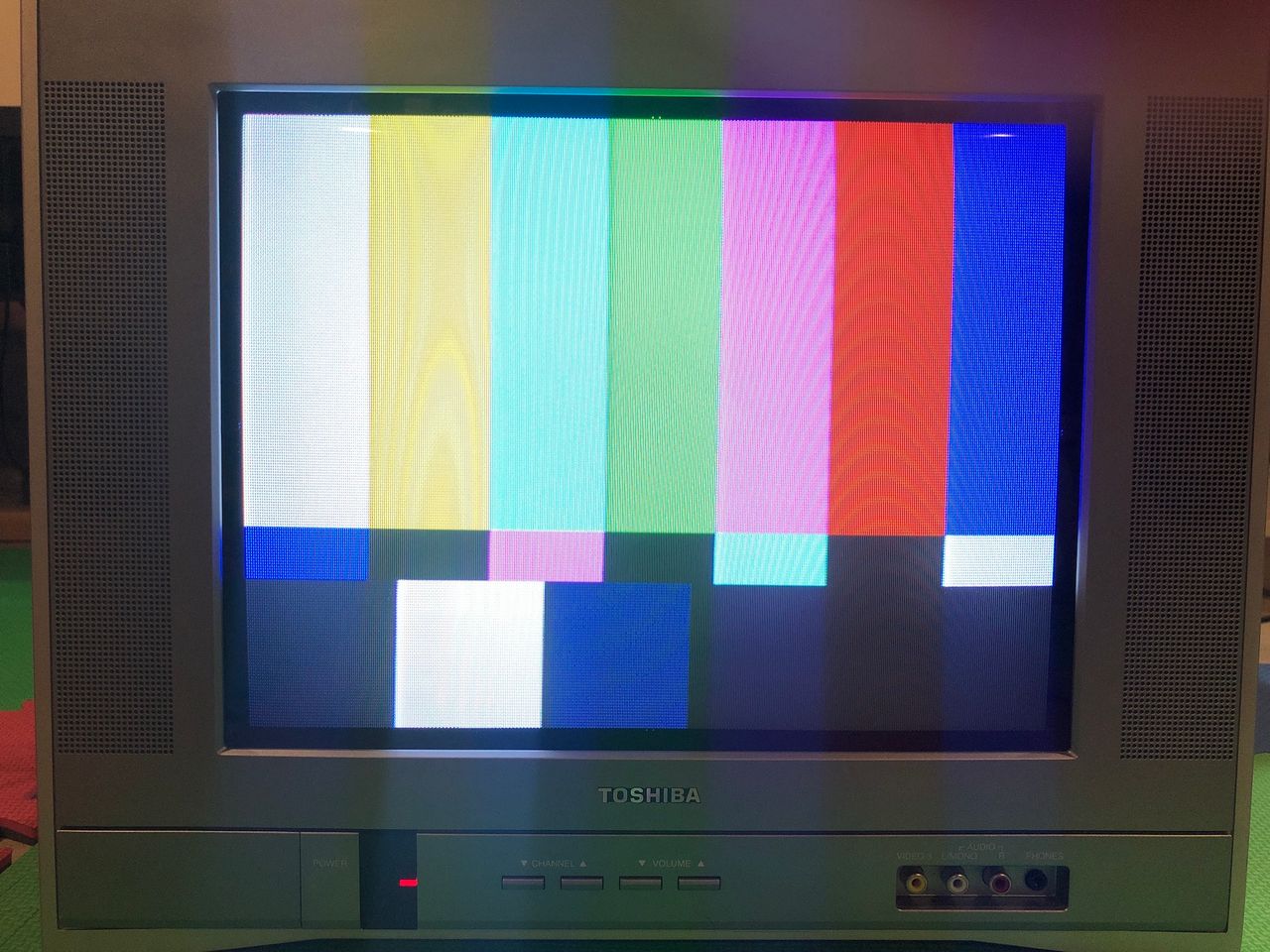
Test patterns
SMPTE Colors 
Infamous Grid 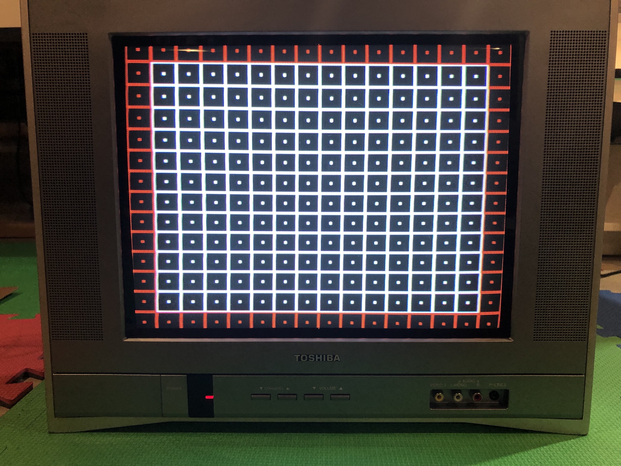
Service Menu Settings
14AF43
| NUM | SETTING | VALUE | FIXED |
|---|---|---|---|
| 00 | OSD | 22 | DEFAULT |
| 01 | DEFAULT | ||
| 02 | H VCO | 3 | DEFAULT |
| 03 | H PHASE | 12 | DEFAULT |
| 04 | AFC GAIN | 6 | DEFAULT |
| 05 | V SHIFT | 0 | DEFAULT |
| 06 | H.SIZE | 0 | DEFAULT |
| 07 | V.SIZE | 28 | DEFAULT |
| 08 | V.LIN | 22 | DEFAULT |
| 09 | VS.CORR | 42 | DEFAULT |
| 10 | R.DRV | 66 | DEFAULT |
| 11 | B.DRV | 71 | DEFAULT |
| 12 | R.BIAS | 127 | DEFAULT |
| 13 | G.BIAS | 152 | DEFAULT |
| 14 | B.BIAS | 151 | DEFAULT |
| 15 | BRI.MAX | 120 | DEFAULT |
| 16 | BRI.CENT | 80 | DEFAULT |
| 17 | BRI.MIN | 50 | DEFAULT |
| 18 | CONT.MAX | 100 | DEFAULT |
| 19 | CONT.CENT | 60 | DEFAULT |
| 20 | CONT.MIN | 18 | DEFAULT |
| 21 | COL.MAX | 90 | DEFAULT |
| 22 | COL.CENT | 61 | DEFAULT |
| 23 | COL.MIN | 00 | DEFAULT |
| 24 | TINT | 54 | DEFAULT |
| 25 | SHARP | 35 | DEFAULT |
| 26 | CB DL | 0 | DEFAULT |
| 27 | CR DL | 0 | DEFAULT |
| 28 | CB PED | 8 | DEFAULT |
| 29 | CR PED | 8 | DEFAULT |
| 30 | PARABOLA | 31 | DEFAULT |
| 31 | CORNER | 31 | DEFAULT |
| 32 | TRAPEZIU | 31 | DEFAULT |
| 33 | LEVEL | 21 | DEFAULT |
| 34 | SEP1 | 8 | DEFAULT |
| 35 | SEP2 | 30 | DEFAULT |
Pictures
Reference Photos