Sony (BA-4) KV-27V40
Sony (BA-4) KV-27V40 CRT RGB mod
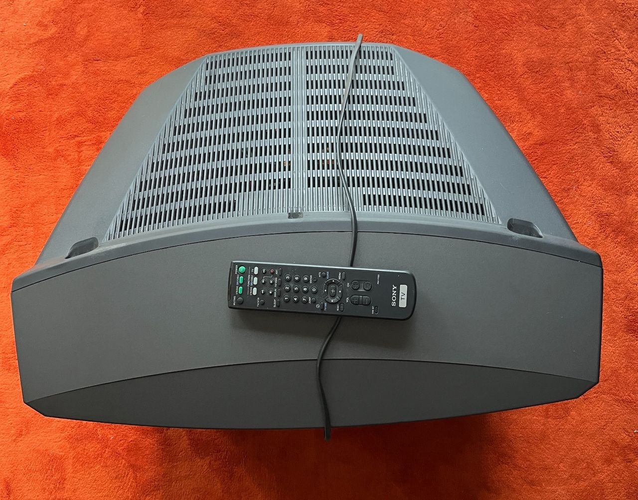
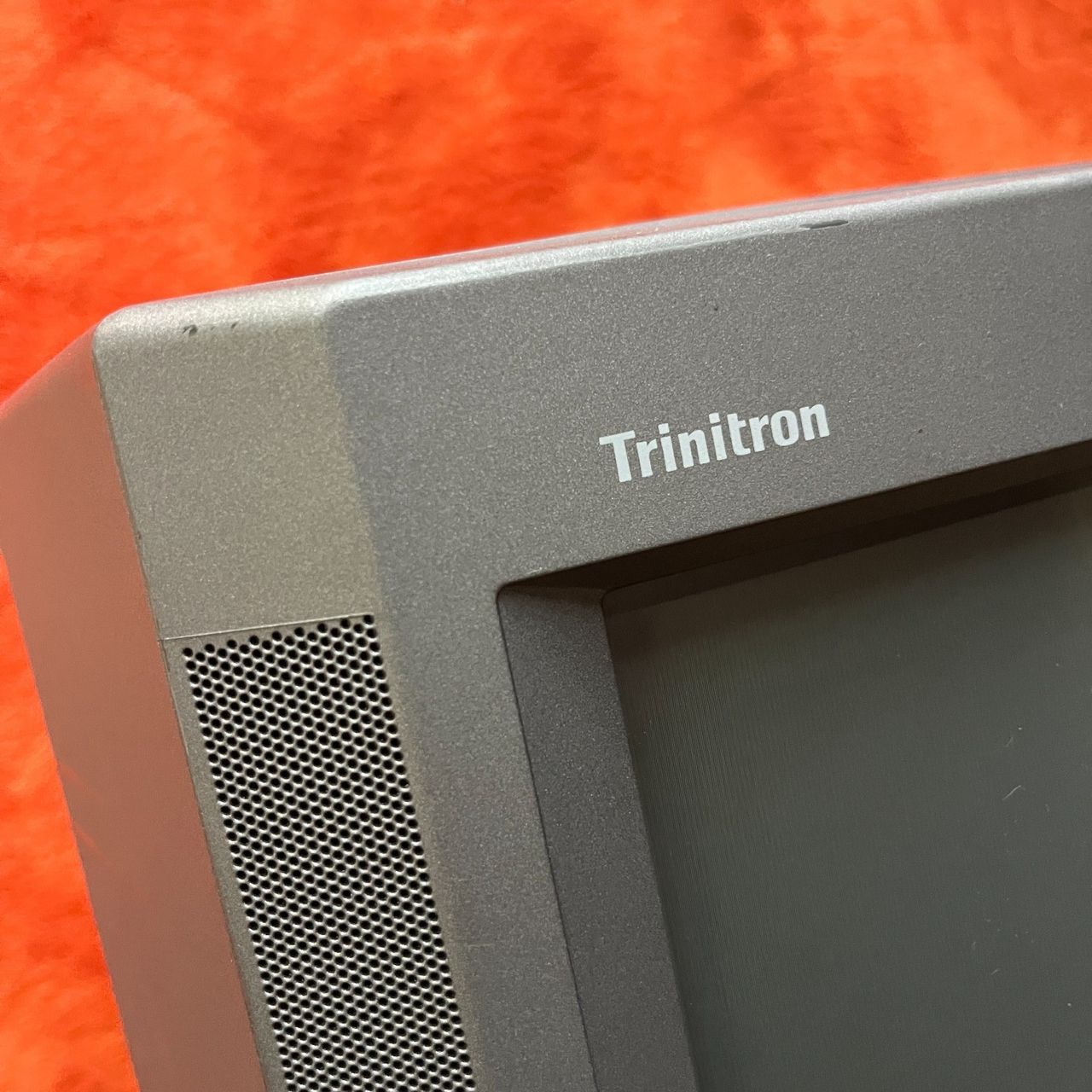
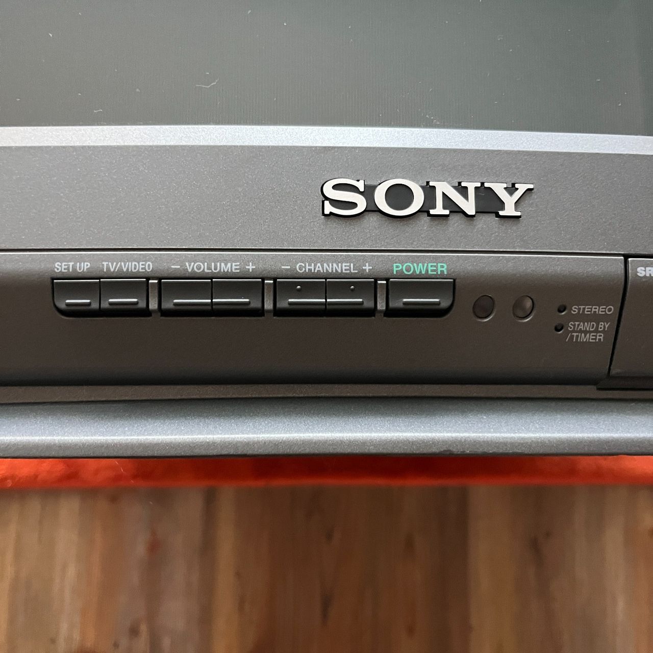
The Sony KV-27V40 is a 27" curved-screen CRT television released in 1999. Built on the BA-4 chassis, it is highly regarded by CRT enthusiasts for its rich colors, exceptional geometry, and deep black levels associated with late-90s premium "V-series" Trinitrons.

View full CRT details and more mod examples →
Instructions below should also apply to these models:
- Sony KV-27V40
- Sony KV-27V45
- Sony KV-27V65
Table of Contents
Contributors
Thank you to everyone who contributed to this guide:
- Kaz Packman — contributor, RGB mod and pictures
- The Funk Wagon Savannah — contributor, Pictures
CRT safety
Caution
You can die doing this! So read carefully! CRT TV is not a toy. Do not open a CRT TV. If you don't have any prior knowledge about handling high voltage devices, this guide is not for you. CRT TV contains high enough voltage (20,000+ V) and current to be deadly, even when it is turned off.
Plan of attack
Manuals and Datasheets
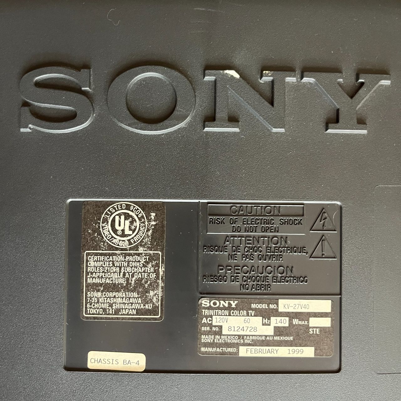
Specs
- Manufactured: Mexico (1999)
- Chassis: BA-4
- Jungle Chip: Sony CXA2061S
- OSD Chip: Mitsubishi M7273MF
- Screen Size: 27"
- Power: 140 W
RGB mux diagram
Prepare the mux diagram. If you are building your own circuit, this diagram should help.
Calculating the RGB external resistor value
Formula from our theory page!

Calcualted 910Ω for 0.7Vp-p. With didoe inline for RGB, you have to use 1kΩ
Performing the mod
Now that you roughly know what needs to be done, prepare for the mod. Place the board on a comfortable place. Make sure you are not putting pressure on the flyback or other components. Taking out the chassis is fairly straight forward on this CRT. There are few wires that needs to be disconnected.
- Degauss wire
- Power wire
- Ground wire attached to the neck board
- Yoke deflection coil wire
- Anode wire (this is the one with the rubber cap)
- Left and right audio wires
Please remember that wires 1-5 are critical for the CRT to function and should not be omitted. Having any of these wires disconnected while powering up can damage the board and can have adverse effects.
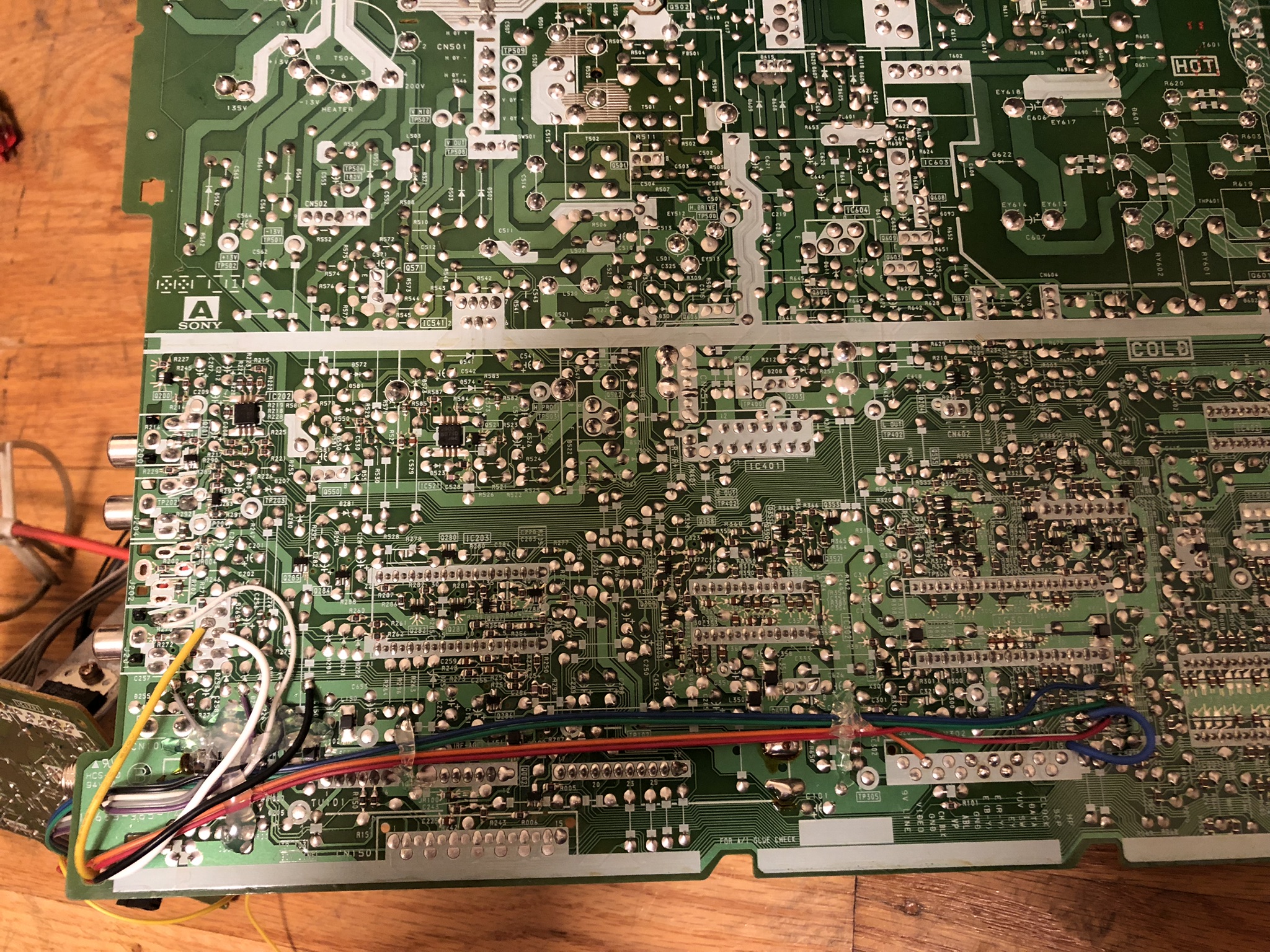
Sometimes it can be overwhelming to see a large chassis. But, we are primarily going to focus on two areas.
Chassis from Sony 20S42 (BA-4D). BA-4 is a similar chassis. 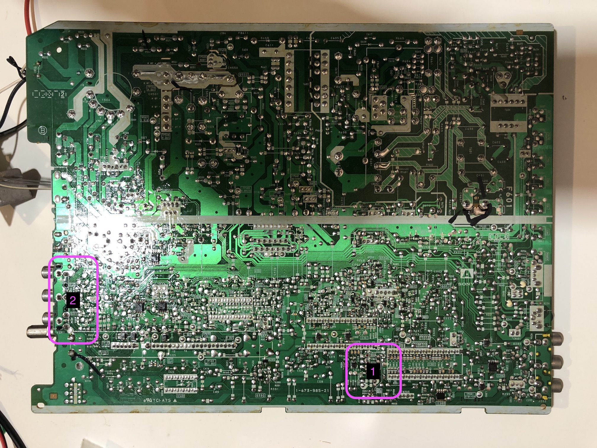
- Area 1: This is where we are going to remove resistors and attach the R, G, B and blanking wires
- Area 2: This is where we are going to connect composite, audio L, R and ground wires
STEP 1: Remove the following components
Zooming in on Area 1.
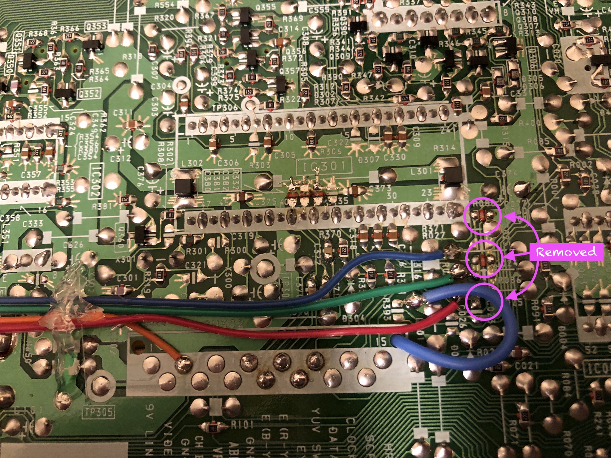
Remove the following components. RGB resistors to the ground. Please always measure and mark them, so that you know you are removing the correct partrs.
- R086 (680Ω) Red ground resistor
- R087 (680Ω) Green ground resistor
- R088 (680Ω) Blue ground resistor
STEP 2: Add RGB inline diodes (optional, but recommended)
To reduce interference, it is recommended to add these inline diodes. You will be lifting one side of the R025, R026, R027 and add diodes.
KV-27V40 - Heat shrink was used in the middle one to avoid shorts. 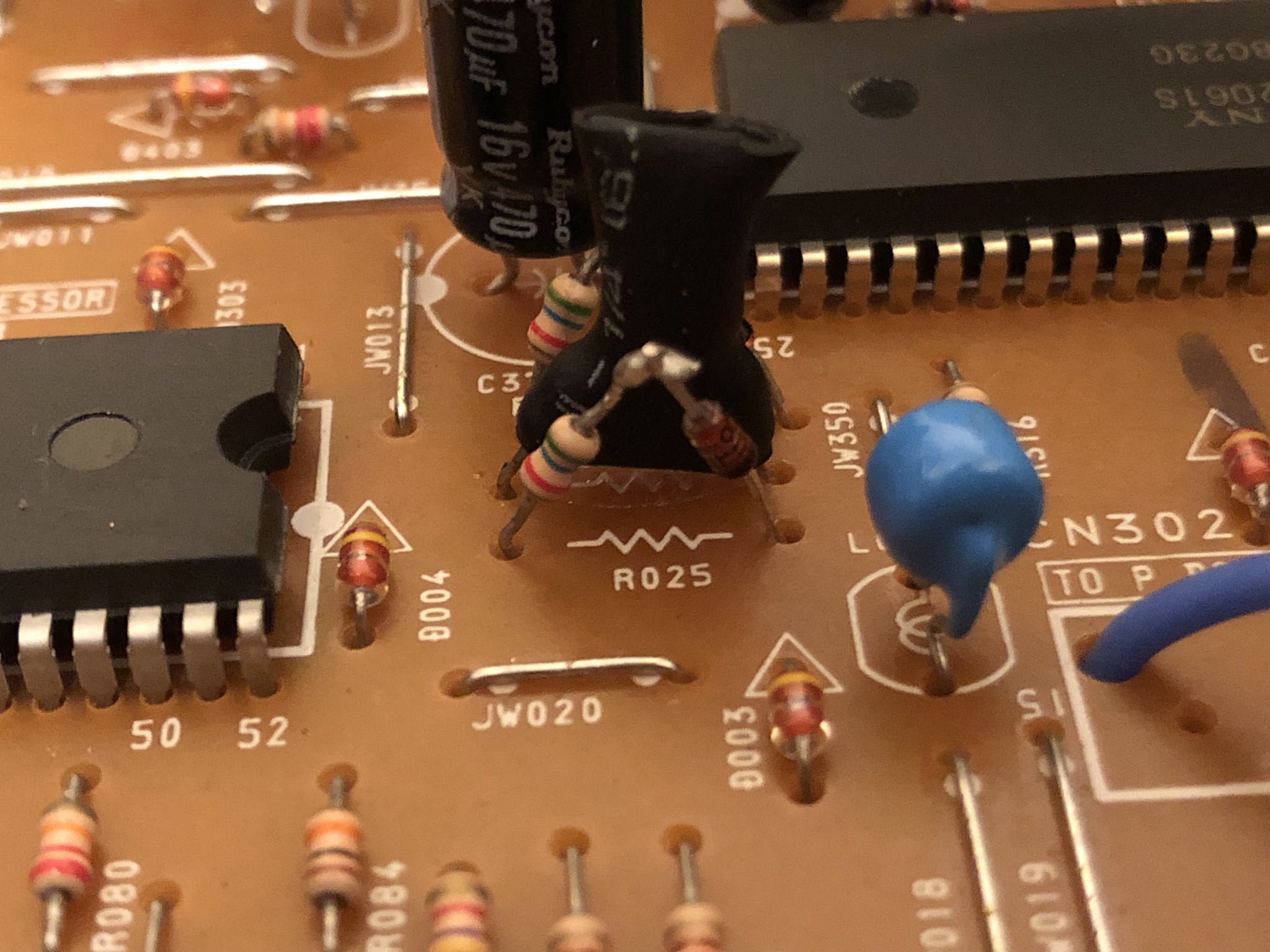
KV-27V42 - Heat shrink was used in the middle one to avoid shorts. 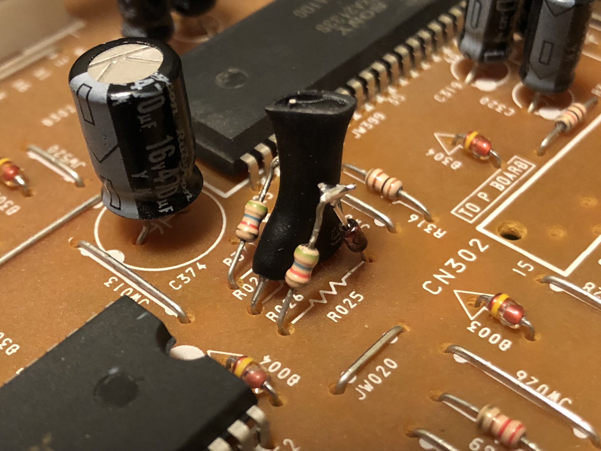
KV-27S42 - Below picture shows before adding the diodes. 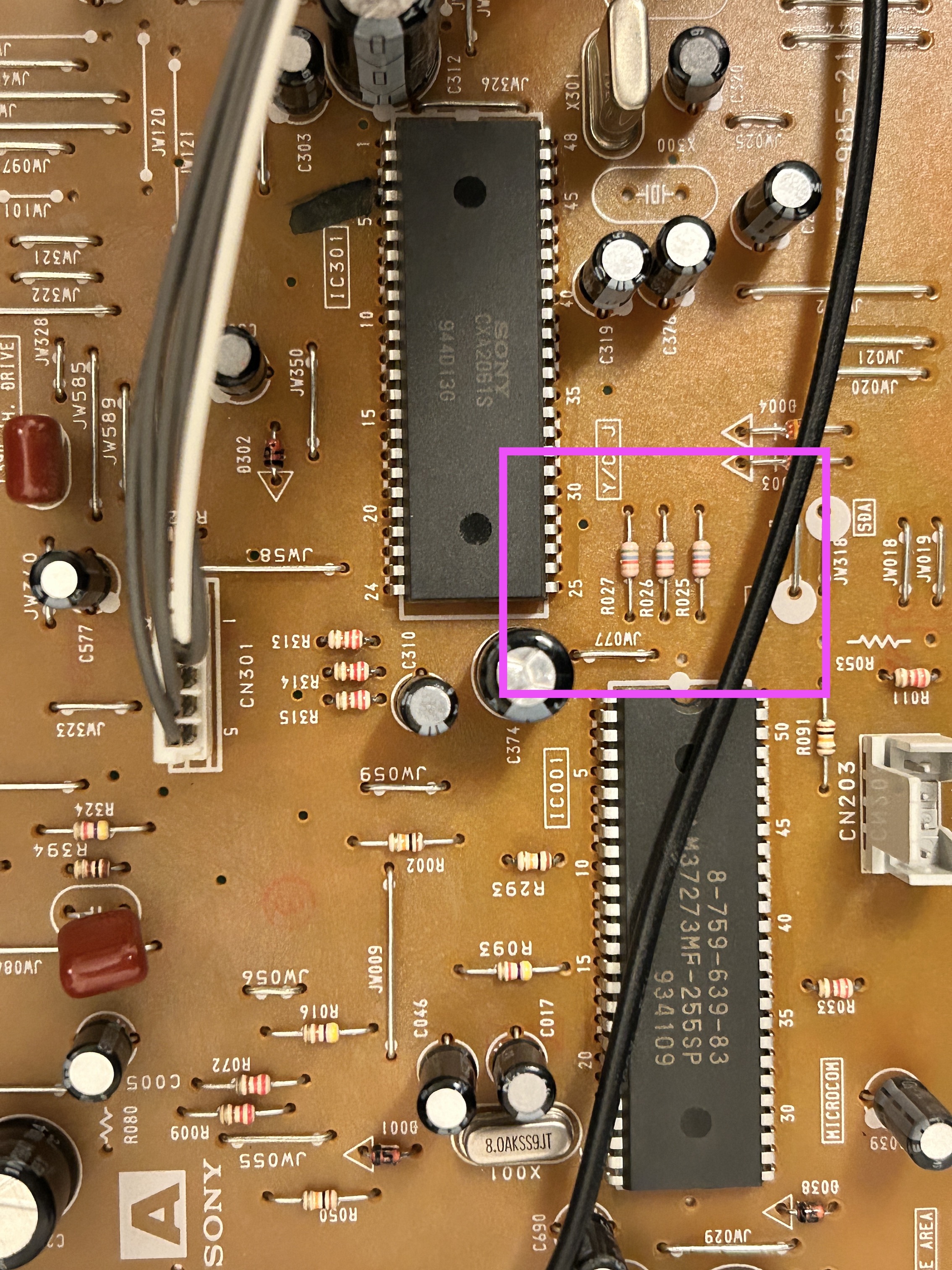
KV-27S42 - After adding diodes inline 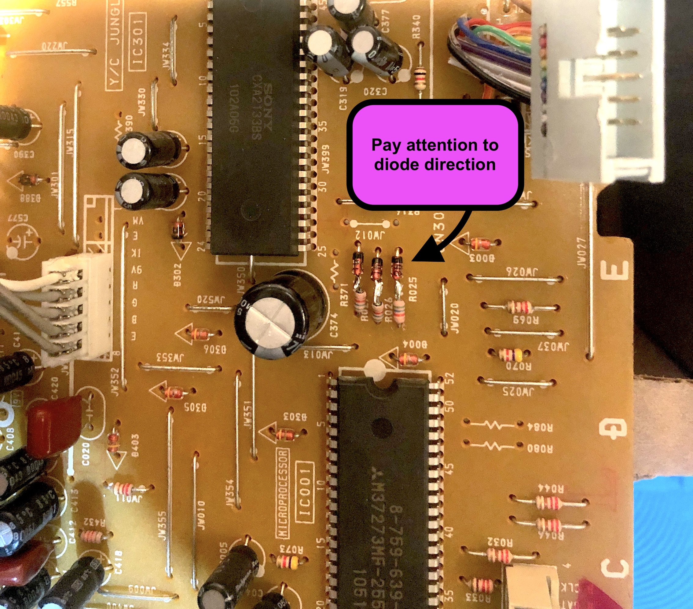
Pay attention to the diode direction and how it was installed. This is extremely important. Otherwise, OSD will not work.
Also, adding didoes means you will need to use 1KΩ resistors on the RGB mux board.
STEP 3: Connect RGBs, Blanking
Then attach the R, G, B and blanking wires to the respective legs of the diodes. Wires should be attached to the side closer to the jungle chip.
- R, G, B wires are red, green and blue respectively
- Thick blue wire here is used for internal blanking through the switch. If you are using the ribbon cable with external blanking, this would be the brown wire.
STEP 4: Connect Sync and Audio
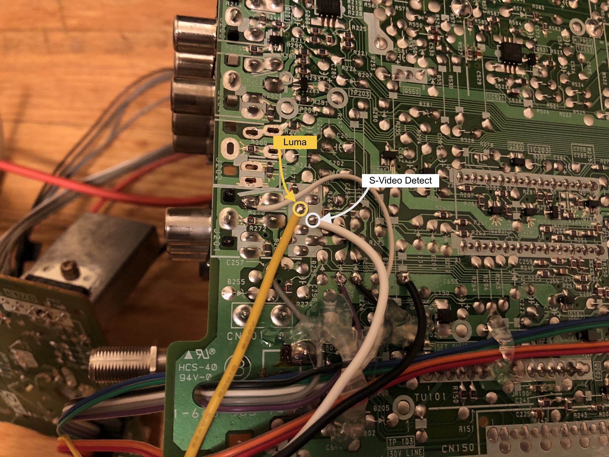
- Thick yellow wire is for sync (luma)
- Thick white wire is for S-Video detect
- Purple and black wires are for ground
- Grey wire is for right audio
- White wire is for left audio
Full board 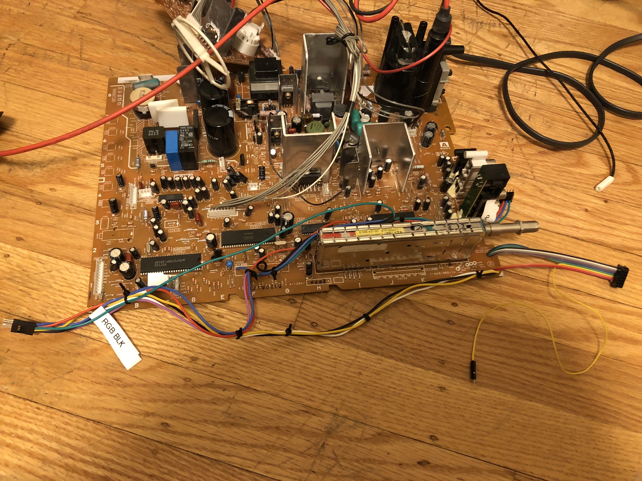
STEP 5: Disconnect the VM cable to reduce artificial sharpening
The Velocity Modulation (VM) connector can be found on the neck board. Disconnecting this is recommended to get the best picture quality from your RGB and YPbPr mods. 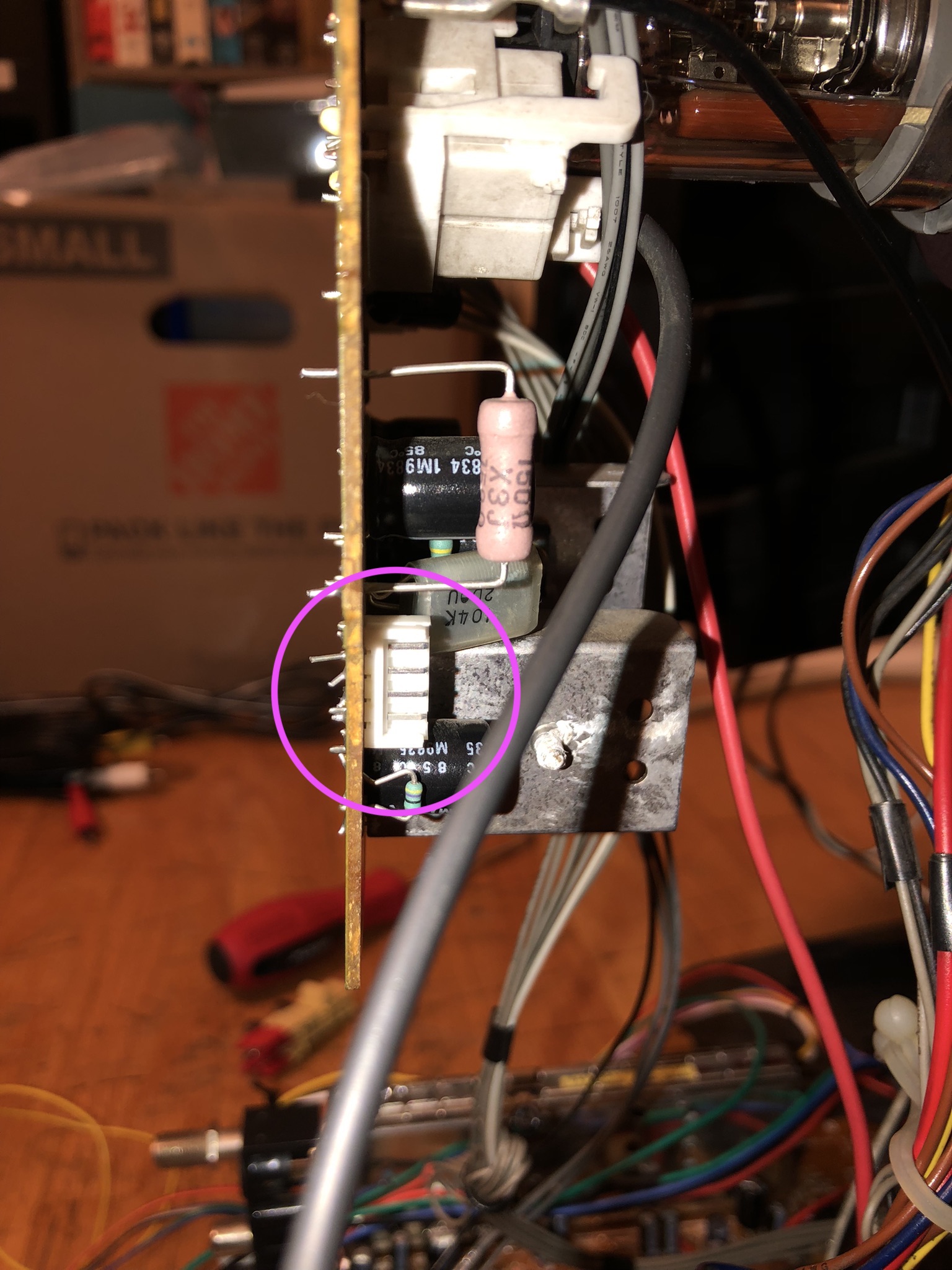
STEP 6: Build your mux board
This mod uses the RGB mux board. This is optional, but will make your mod easier and stable. You can also create the circuit presented in the schematics above without the board. Please also checkout the mux calculator to play with your own values.
| On Sony CRT Chassis | KV-27V40 |
|---|---|
| CRT RGB inline resistor | 5.6kΩ |
| CRT RGB ground resistors removed | 680Ω |
| 0.1μF caps replaced | No |
| Add diodes on chassis RGB lines? | Yes |
| Add blanking diode on chassis | No |
| RGB mux board | KV-27V40 |
|---|---|
| Mux board RGB termination (R1, R2, R3) | 75Ω |
| Mux board RGB inline resistors (R4, R5, R6) | 1kΩ |
| Mux board Audio LR (R7, R8) | 1kΩ |
| Mux board blanking diode (R9) | 1N4148 |
| Mux board blanking ground resistor (R10) | open |
| Mux board blanking resistor (R11) | 1kΩ |
| Mux board transistor base resistor (R12) | 1kΩ |
| Mux board transistor (Q1) | PN2222A |
Compatible mux boards:
On this particular CRT, Kaz chose to not use the external blanking signal. Instead, a switch was used to blank. Therefore, the blanking resistor (R11) and diodes (R9) are not populated. 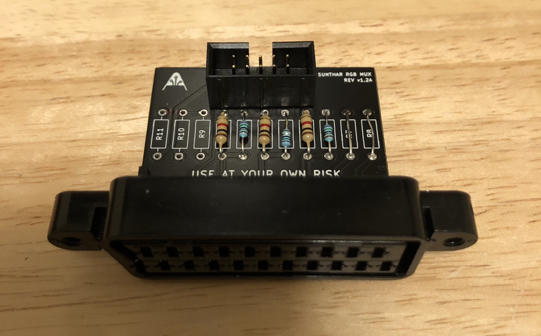
5V for blanking was tapped from this location. There are also other possible locations on the chassis where 5V can be tapped from. ![]()
STEP 7: YPbPr mod
This mod uses the 3P3T switch for blanking between YPbPr and RGB 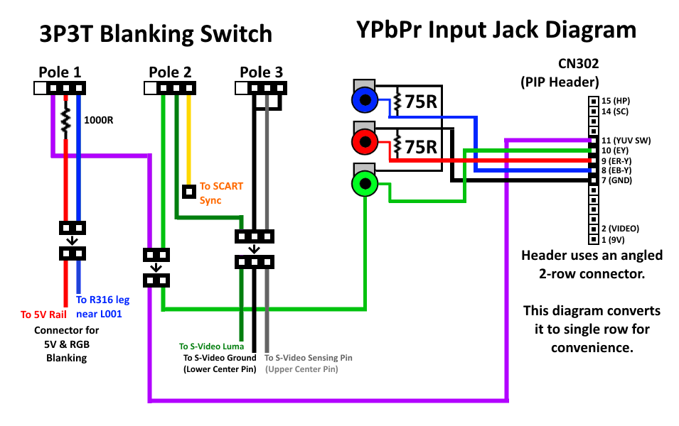
Remove 0.01uF caps C380, C381, C382 and populate C371, C372 and C373 with 0.01uF caps. It's convenient to just move these ground capacitors over to the empty spots. 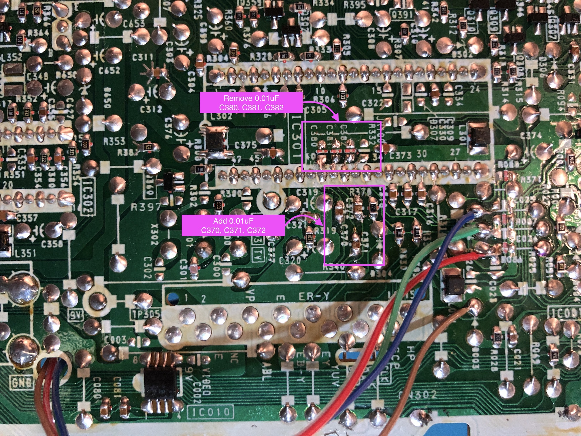
YPbPr wiring on the chassis 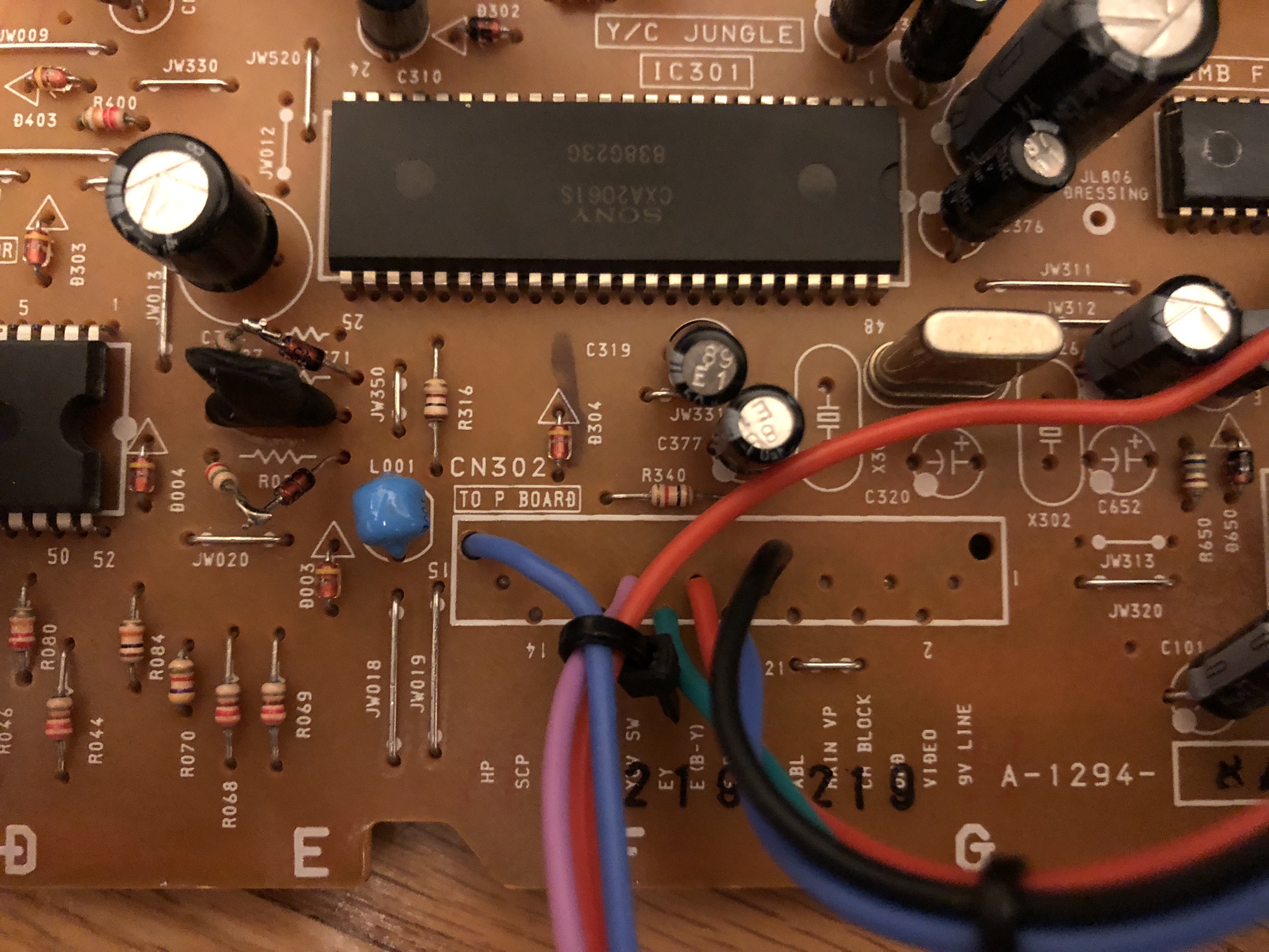
To provide greater clarity, the following image illustrates the correct connections for the wires. This image was sourced from the Sony KV-27S42, but the concept remains consistent. 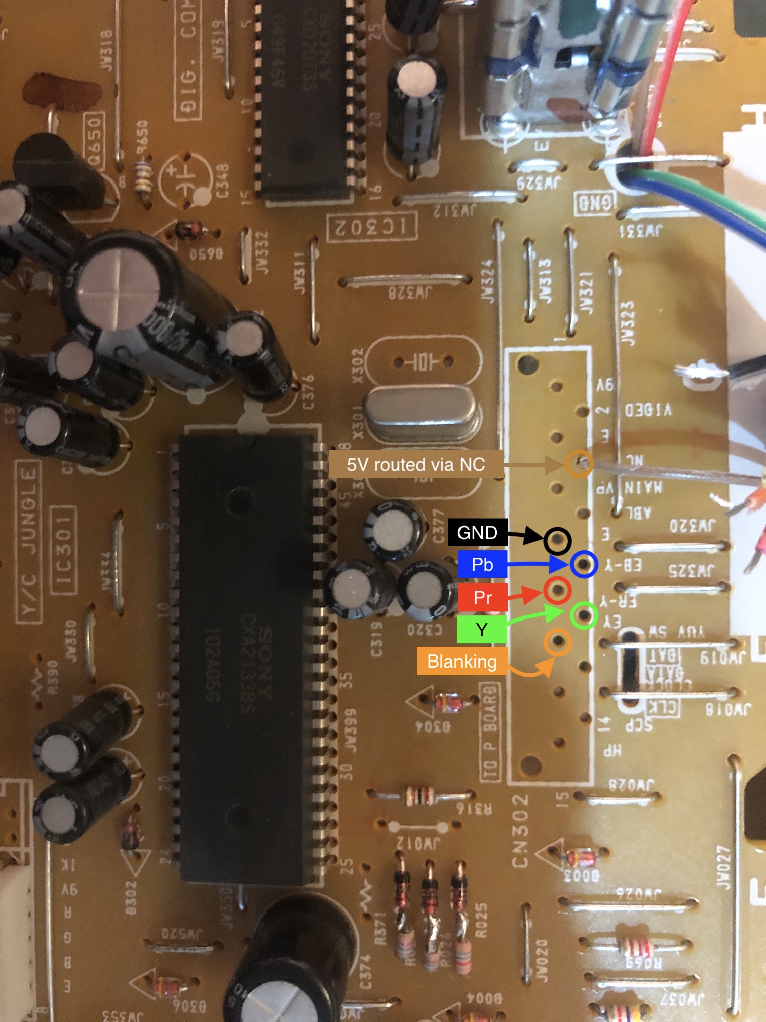
STEP 8: Attach the female SCART connector to TV
Creating a SCART cutout and mounting it is an art. I have a dedicated section for it. How to create and mount a SCART female plug?
Depending on your CRT, you might need to find a good place to mount the SCART port.
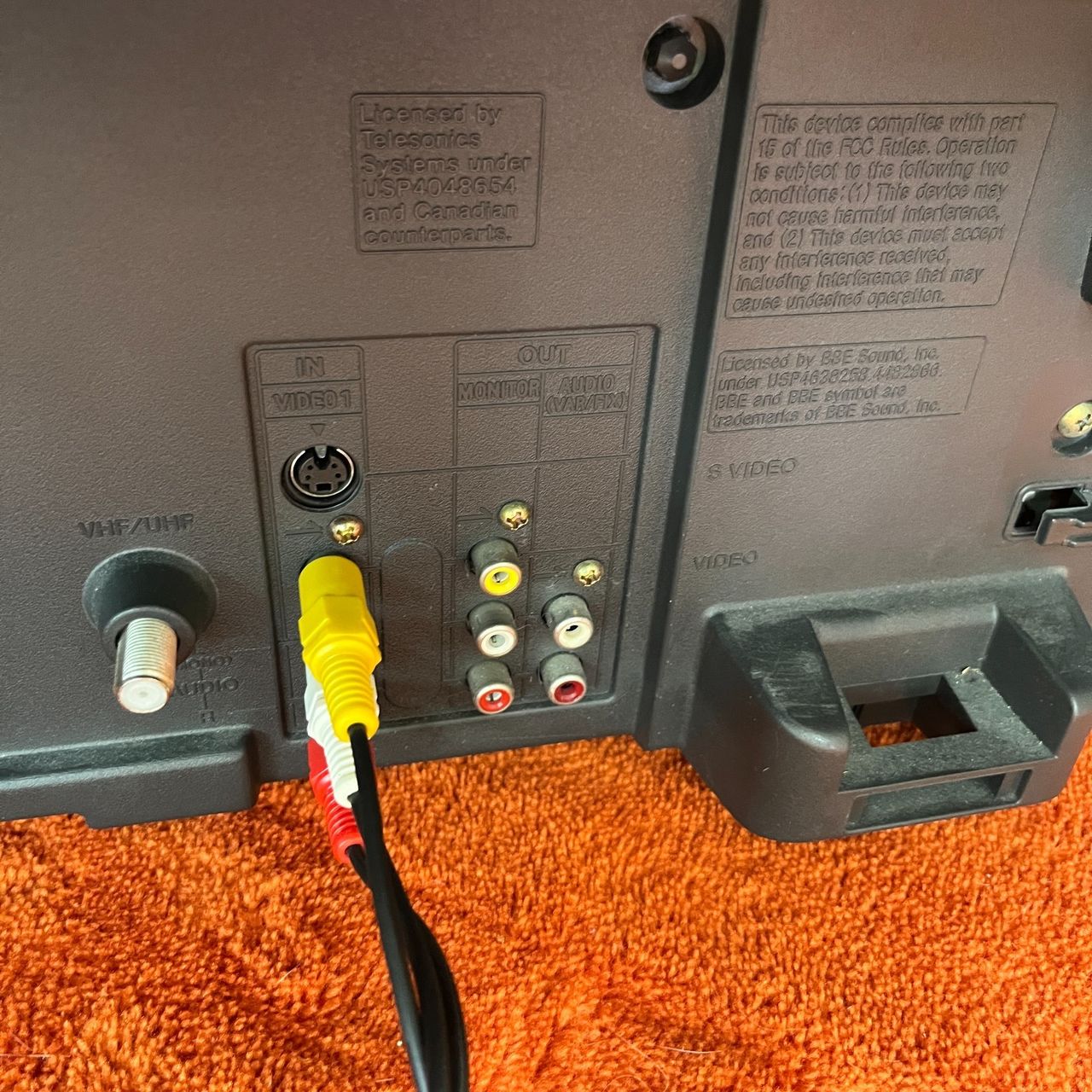
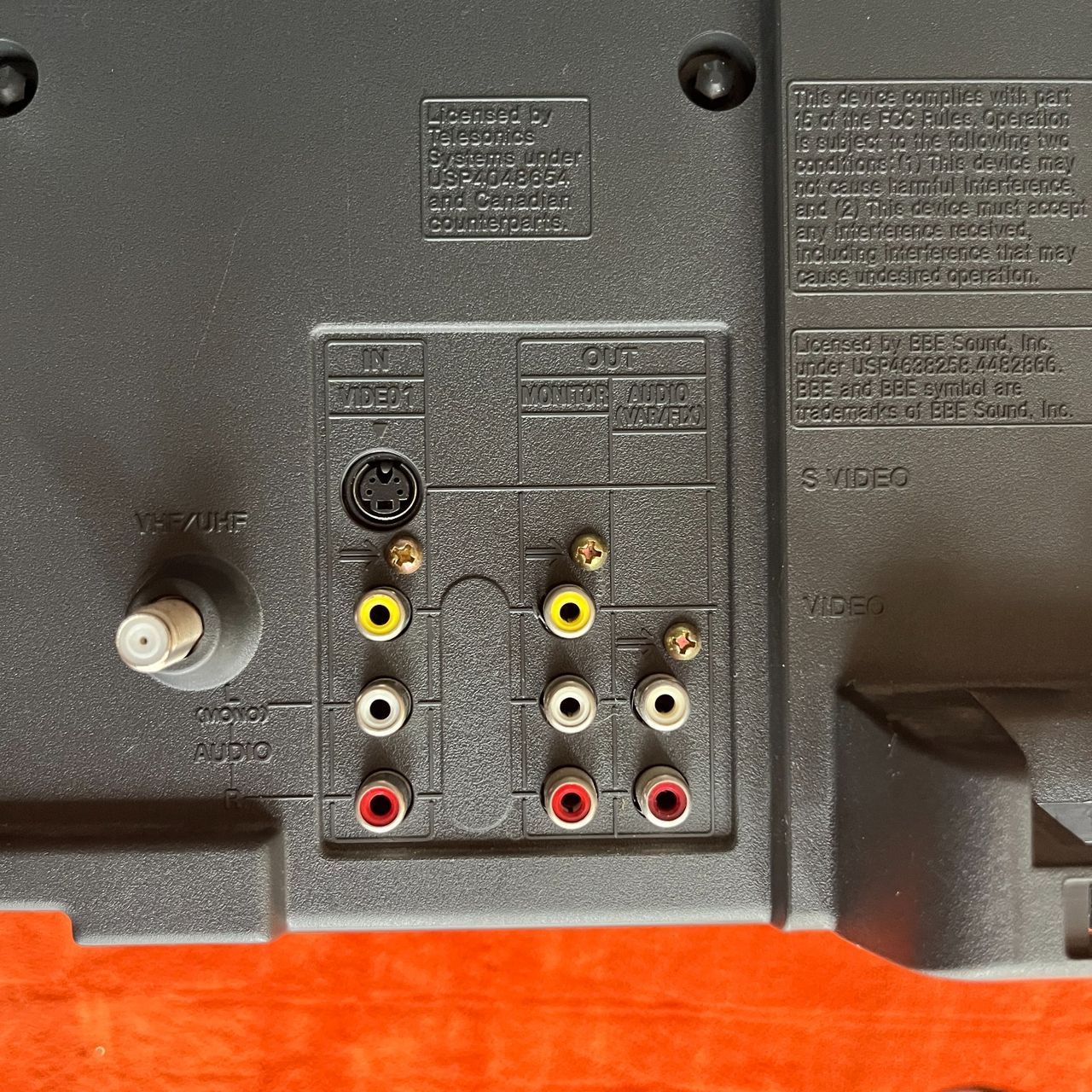
Sony KV-27V40 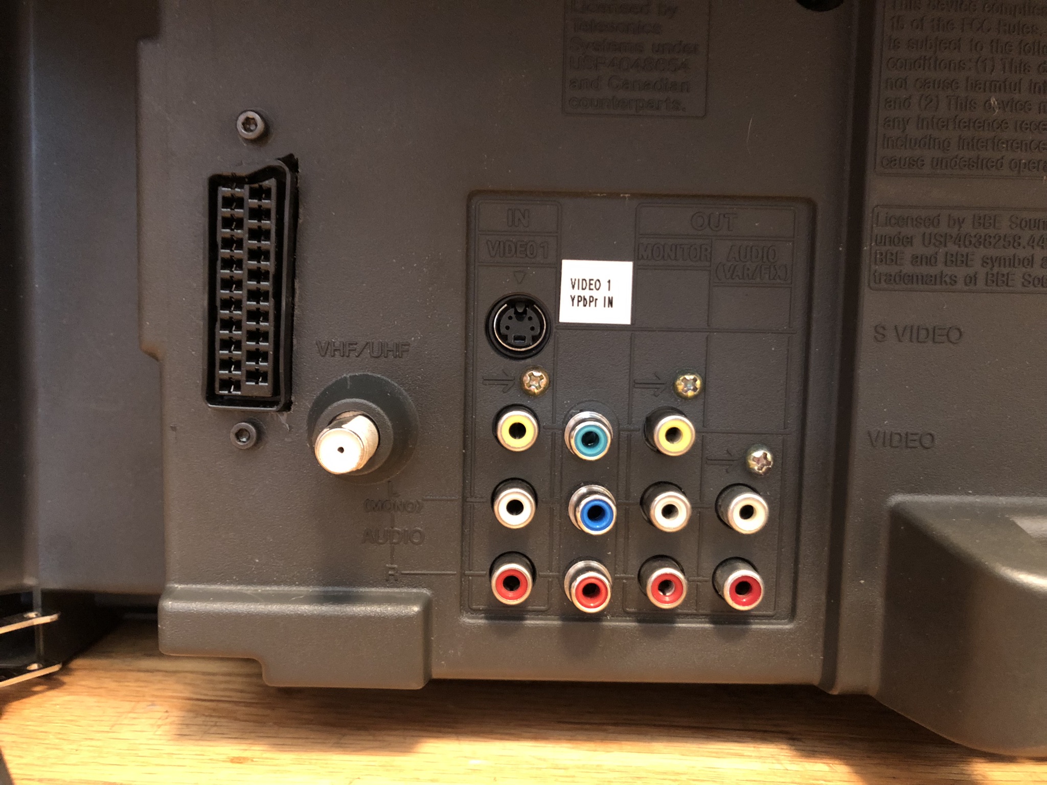
Holes for an unused AV jack were used for YPbPr jacks for a factory look.
Reducing interference
Sometimes you might notice micro interference in the video signals. This is expected. To reduce it, try the following.
- Use diodes in-line for RGB signal
- Make sure your blanking wire is connected after the diode that feeds into the chroma chip (see diagram)
- Try routing most of the cabling below the PCB
- Keep the ribbon cable short
- I really didn't find any difference in interference in using shielded vs non-shileded cables. Therefore, this is optional.
Getting into the service menu
- Turn the set on and then put into standby
- Press the
Display,5,VOL +buttons in sequence - Turn on the CRT and you should be in service mode
- Use buttons "1" and "4" on the remote control to navigate the service menu
- Use buttons "3" and "6" to adjust the selected data
Pictures of the mod
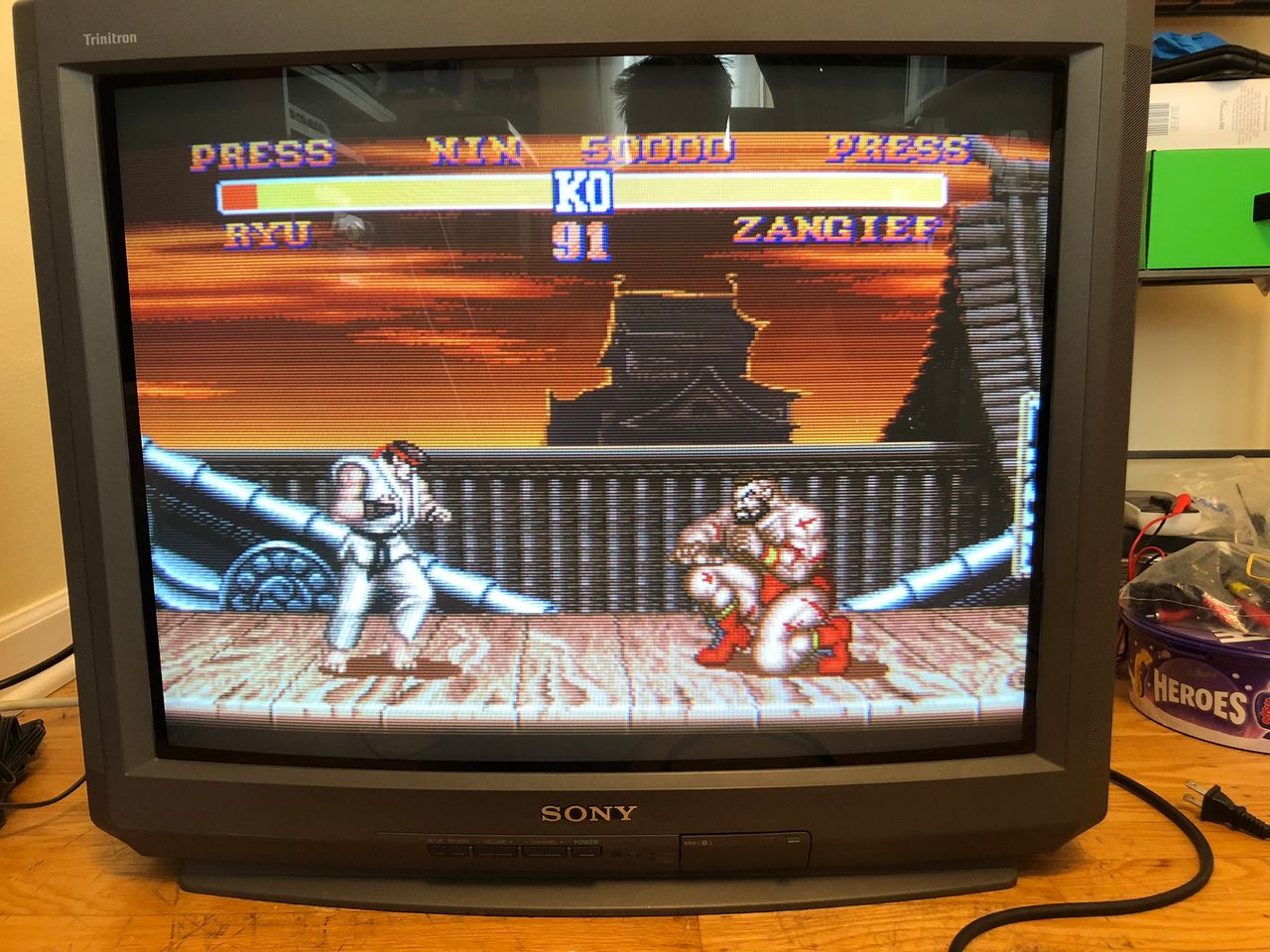
Games (KV-27V40)
Street Fighter II 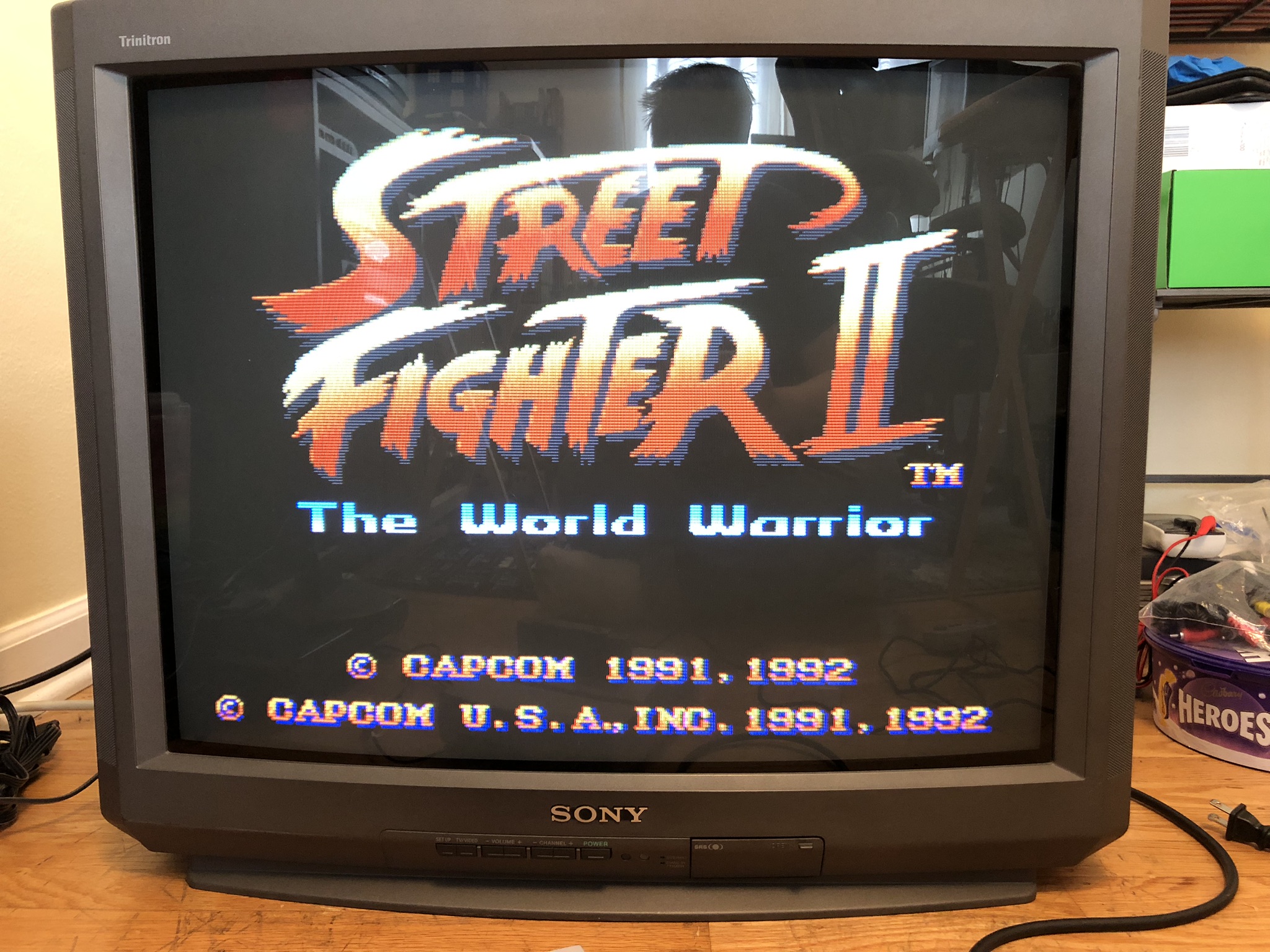
Street Fighter II 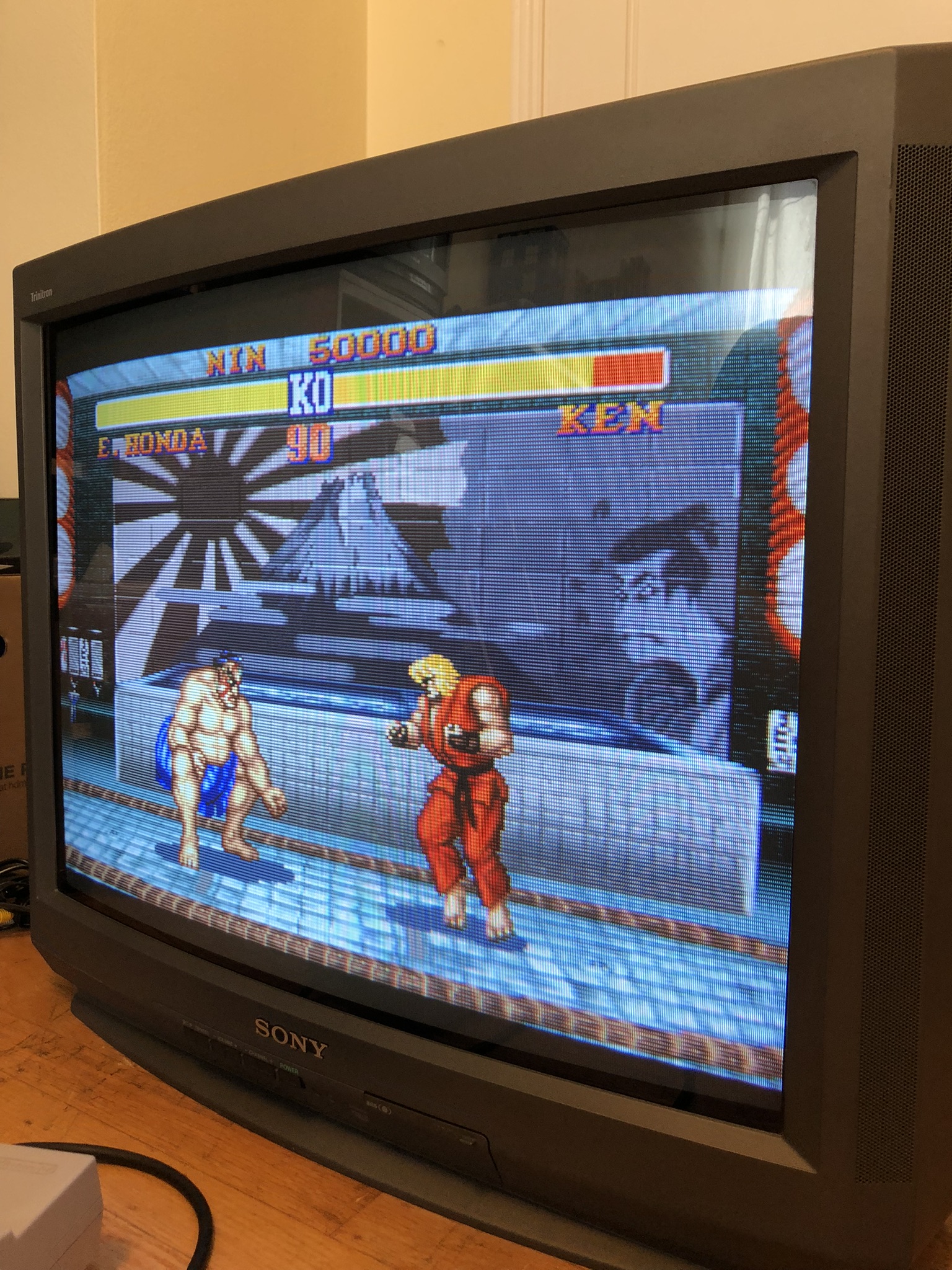
Street Fighter II 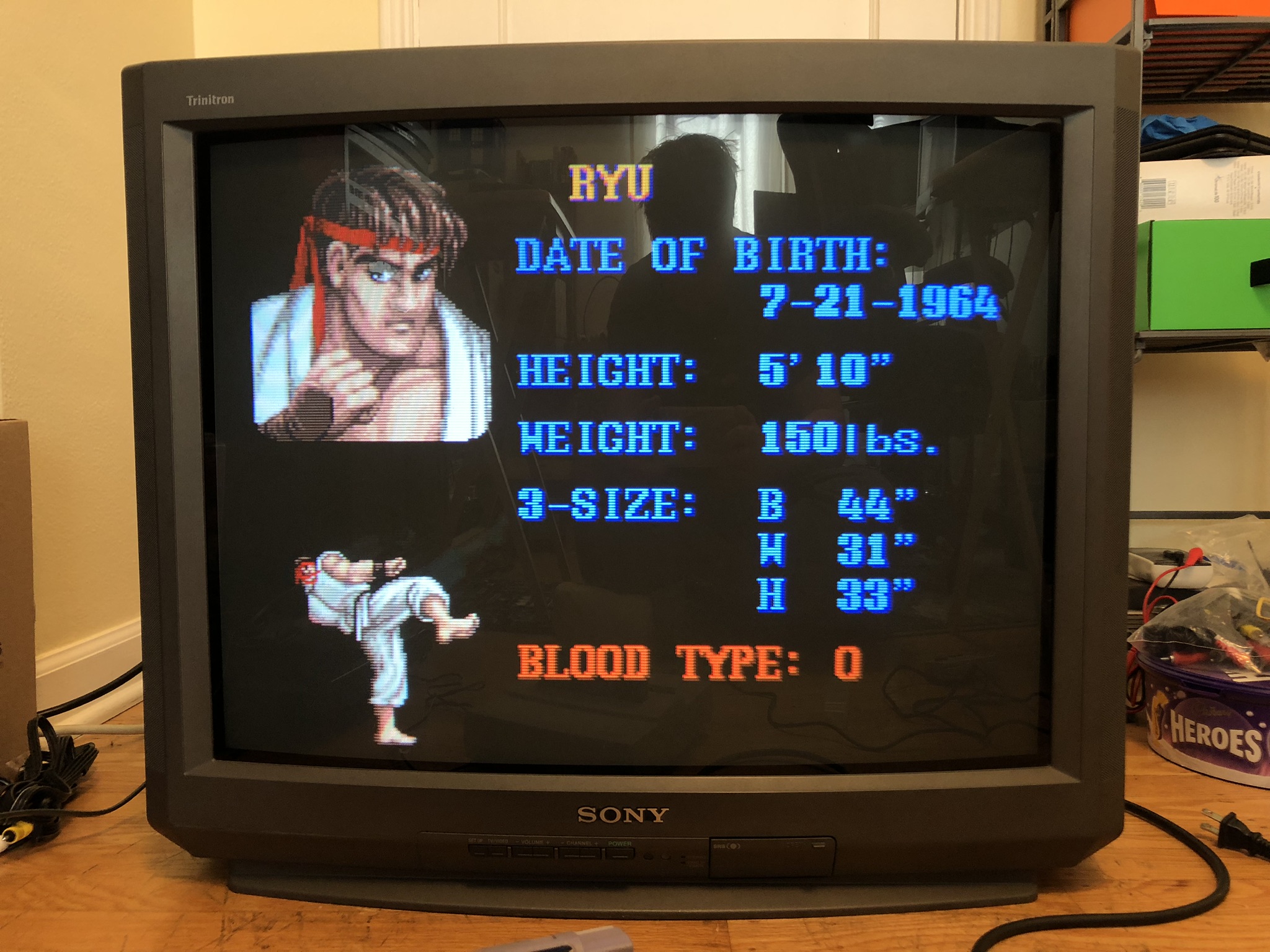
Street Fighter II 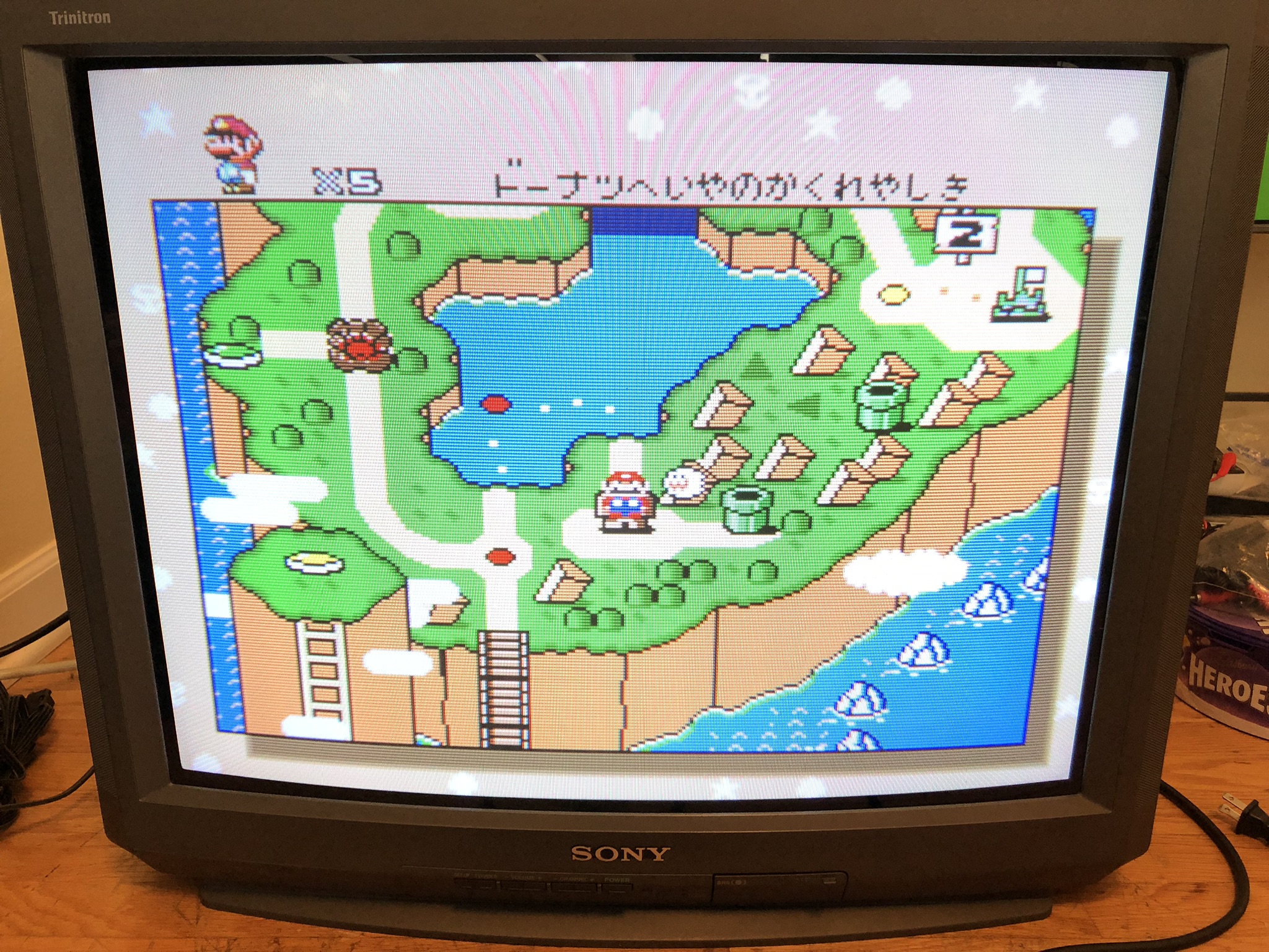
Set
Full back 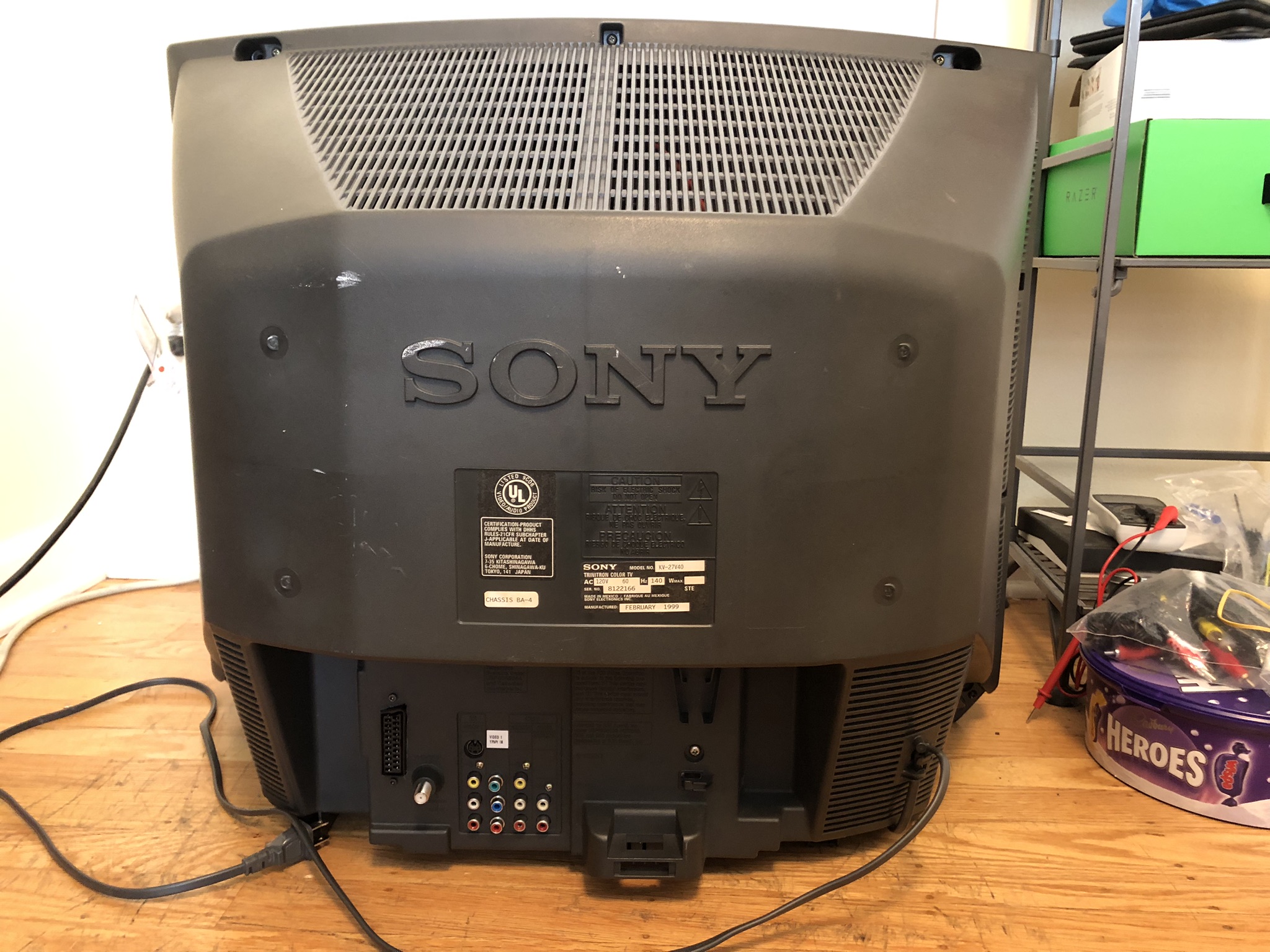
Back label 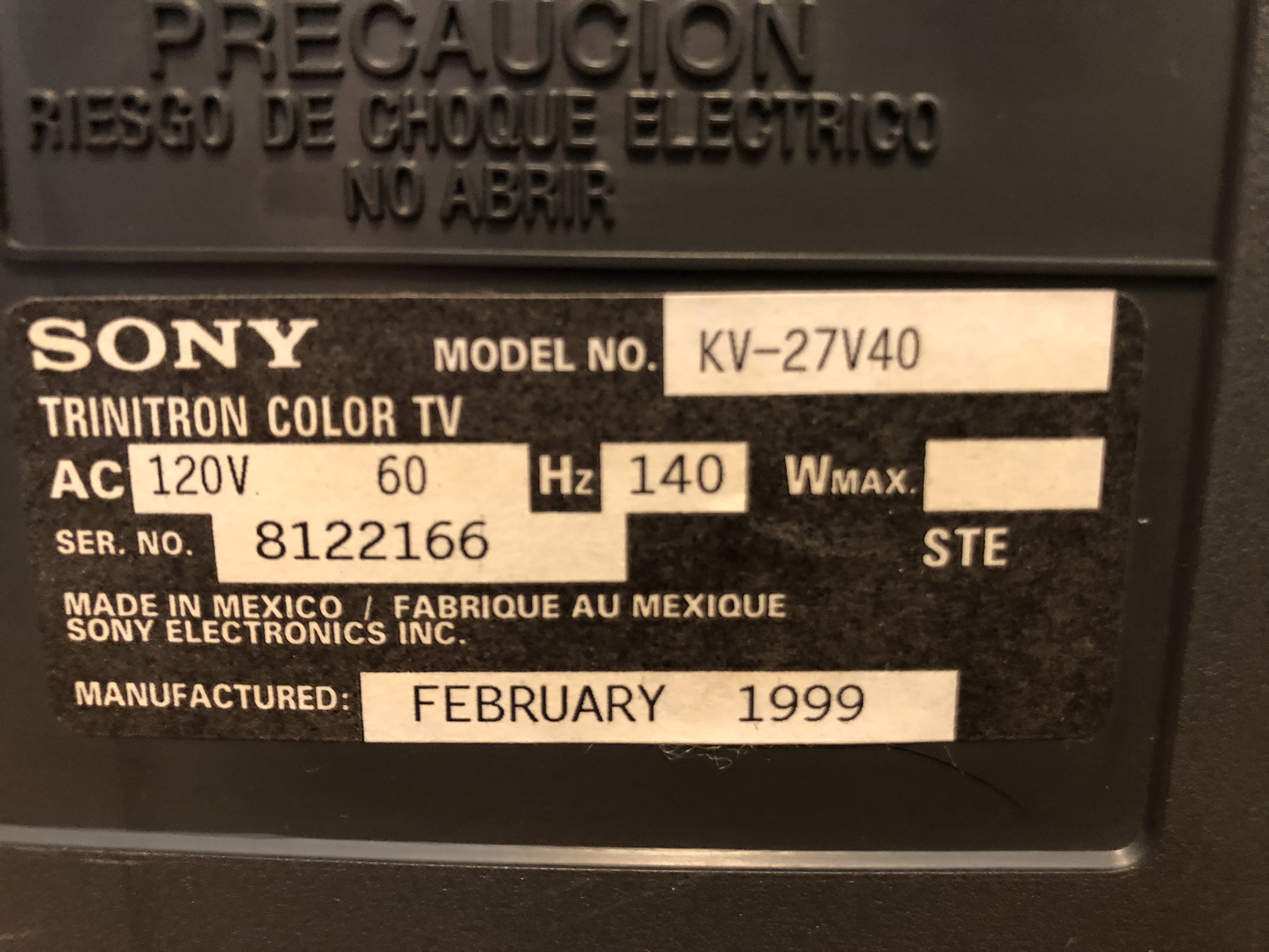
Pictures
Reference Photos