Apex AT2408S
Apex AT2408S CRT RGB mod
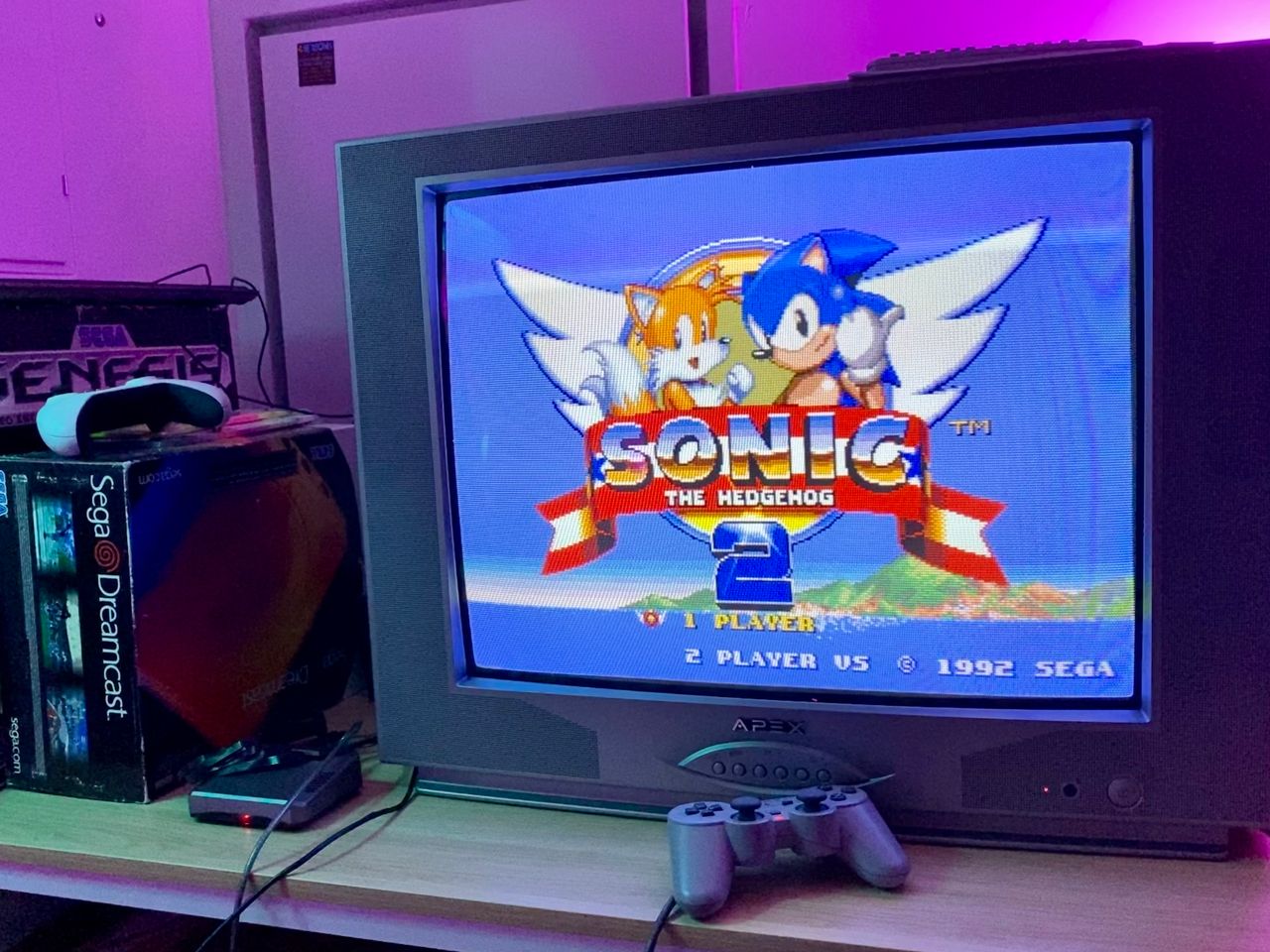
The Apex AT2408S is a 24" CRT tv produced around 2002 by Apex Digital, an American brand known for budget-friendly electronics, with manufacturing often outsourced to Chinese companies.
View full CRT details and more mod examples →
Contributors
Thank you to everyone who contributed to this guide:
- Garry Harman — author, RGB mod and pictures
CRT safety
Caution
You can die doing this! So read carefully! CRT TV is not a toy. Do not open a CRT TV. If you don't have any prior knowledge about handling high voltage devices, this guide is not for you. CRT TV contains high enough voltage (20,000+ V) and current to be deadly, even when it is turned off.
Plan of attack
Manuals and Datasheets
Specs
- Year:
- Chassis: CH-10C1(S)
- Jungle Chip: OM8839
- OSD Chip: CH04T1009
- Screen Size: 24"
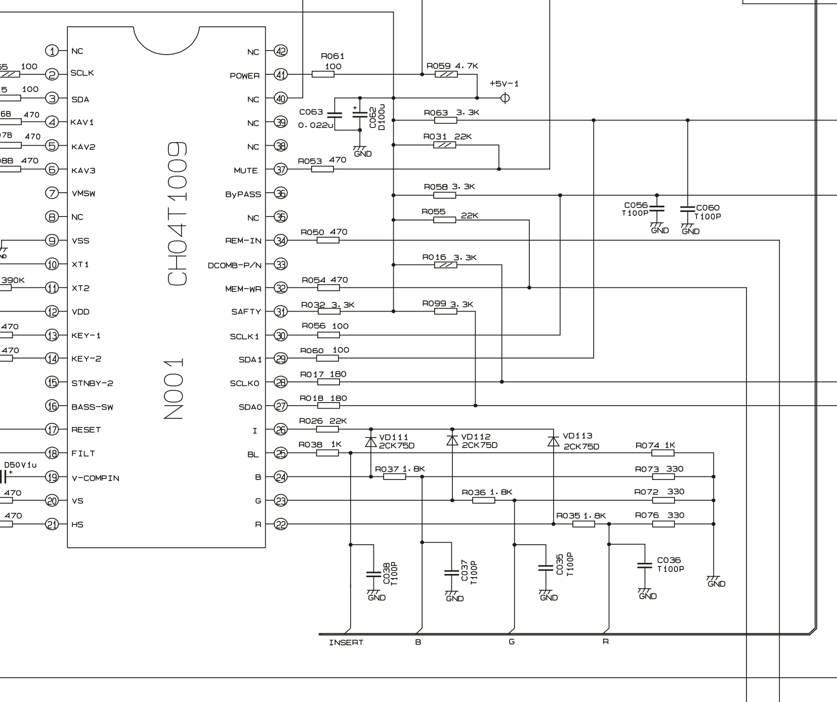
Schematics
Get hold of the schematics for your TV. Understand where the RGB and Fast Blanking signals go from OSD to the Jungle (Chroma) chip.
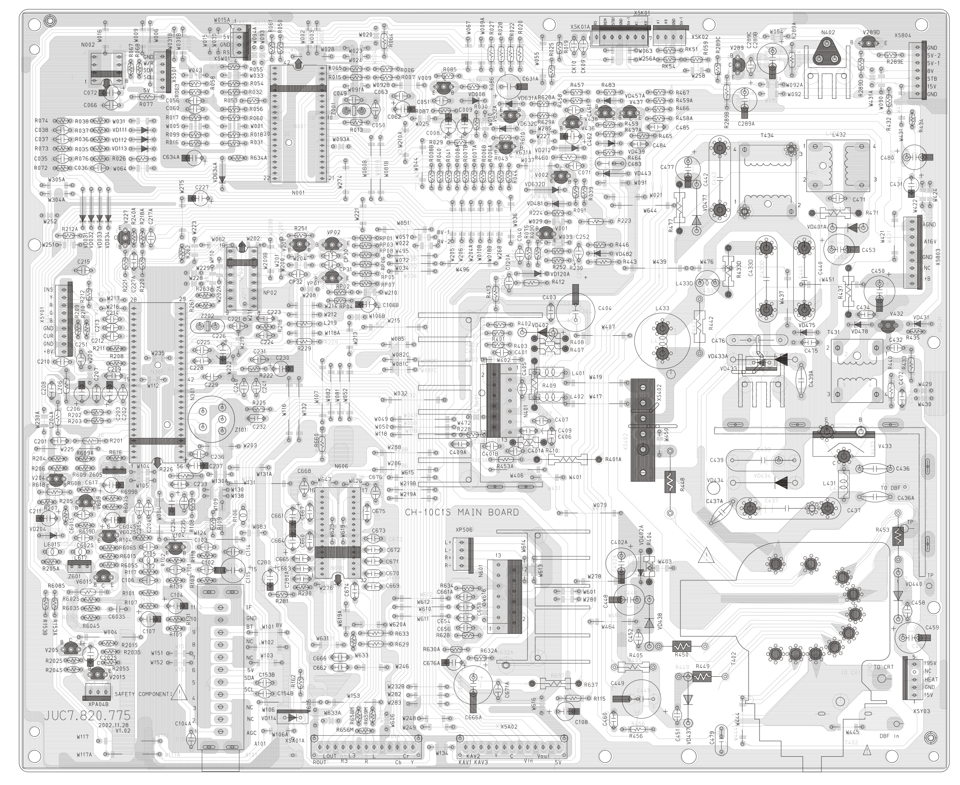
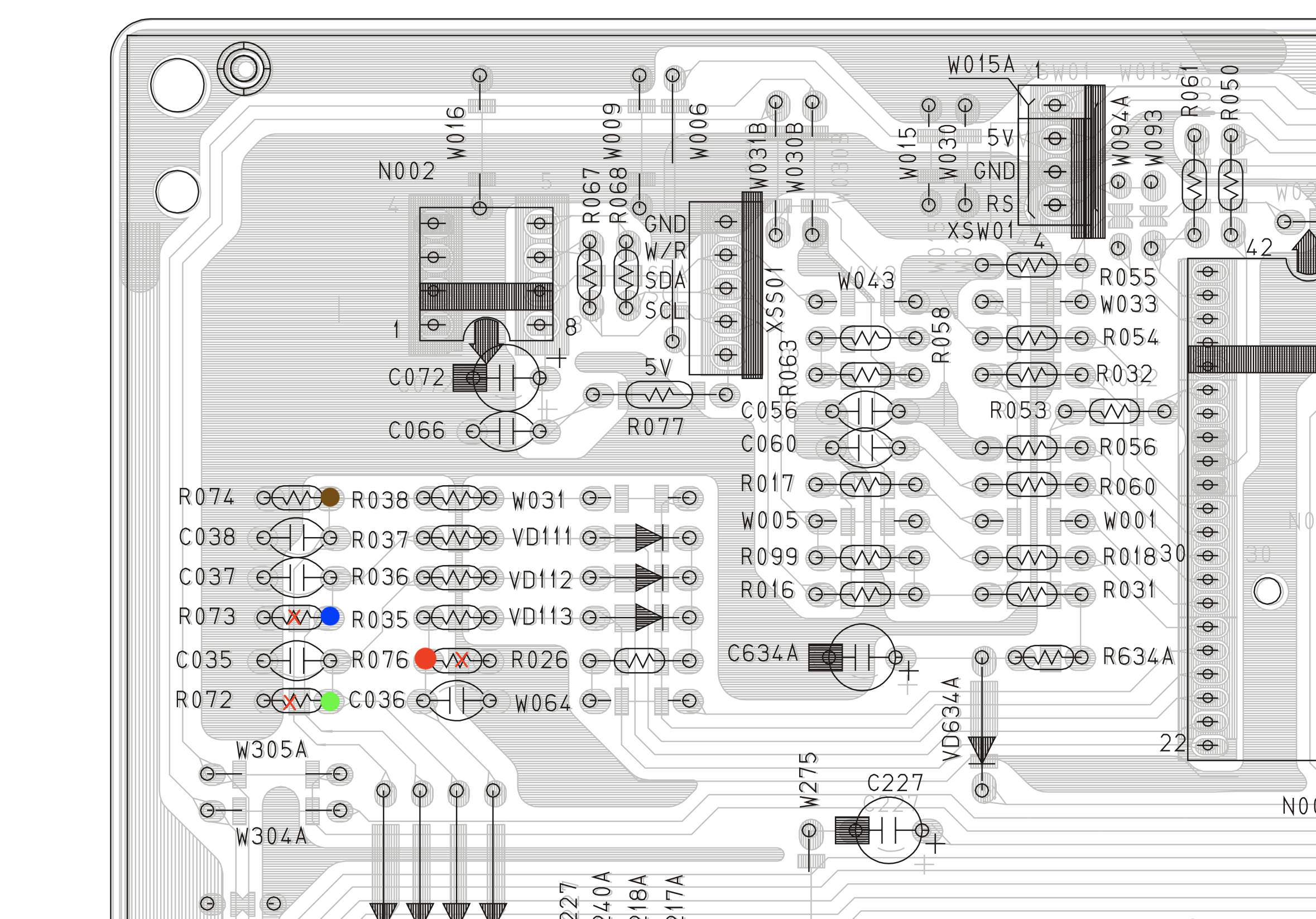
PCB
Points where the R, G, B and Blank wires should be connected are marked with colored dots.
RGB mux diagram
Prepare the mux diagram. If you are building your own circuit, this diagram should help.
Performing the mod
STEP 1: Remove the following components
Remove the RGB resistors to ground
- R073
- R072
- R076
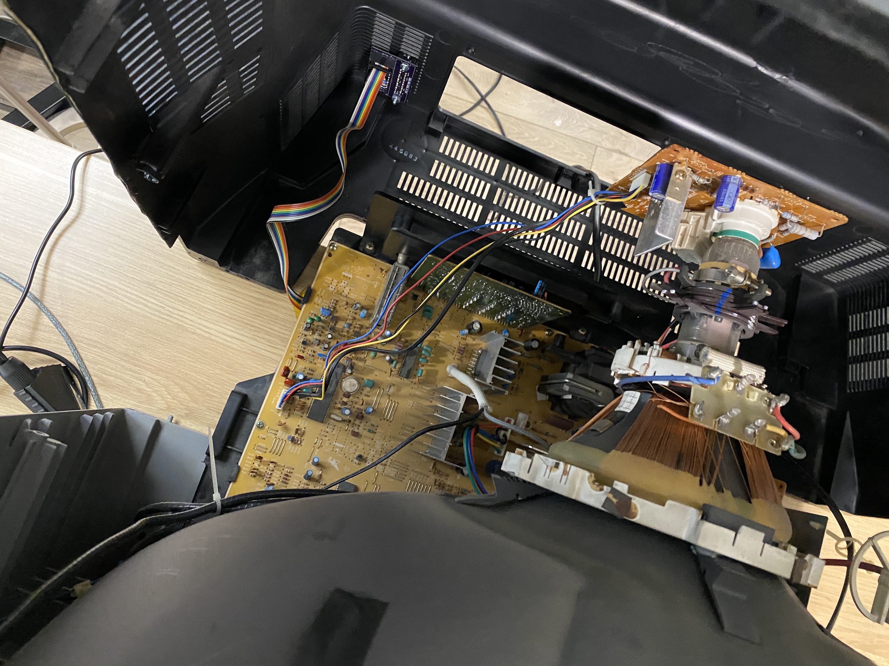
STEP 2: Connect RGBs, Blanking and Audio
Connect the RED, GREEN, BLUE, BLANKING wires 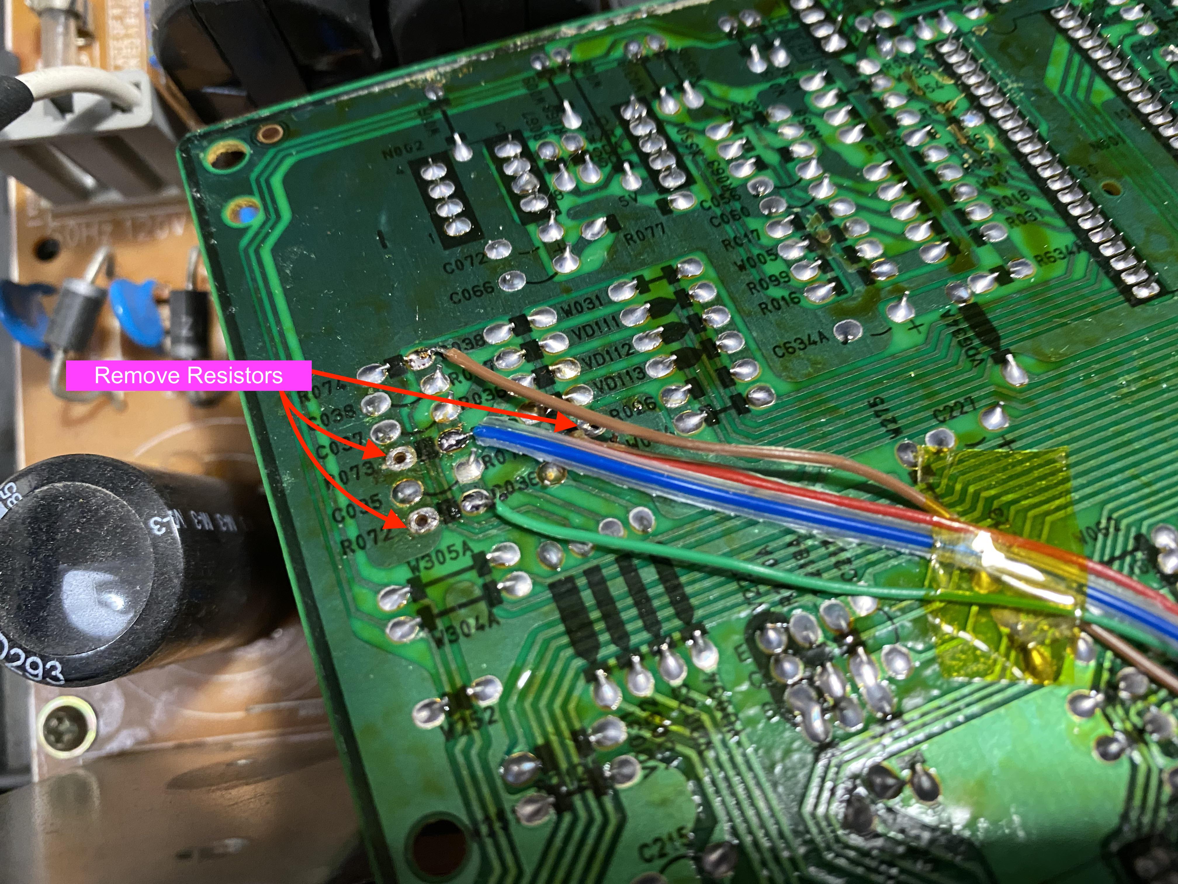
Connect the SIGNAL, AUDIO RIGHT, AUDIO LEFT, GROUND wires 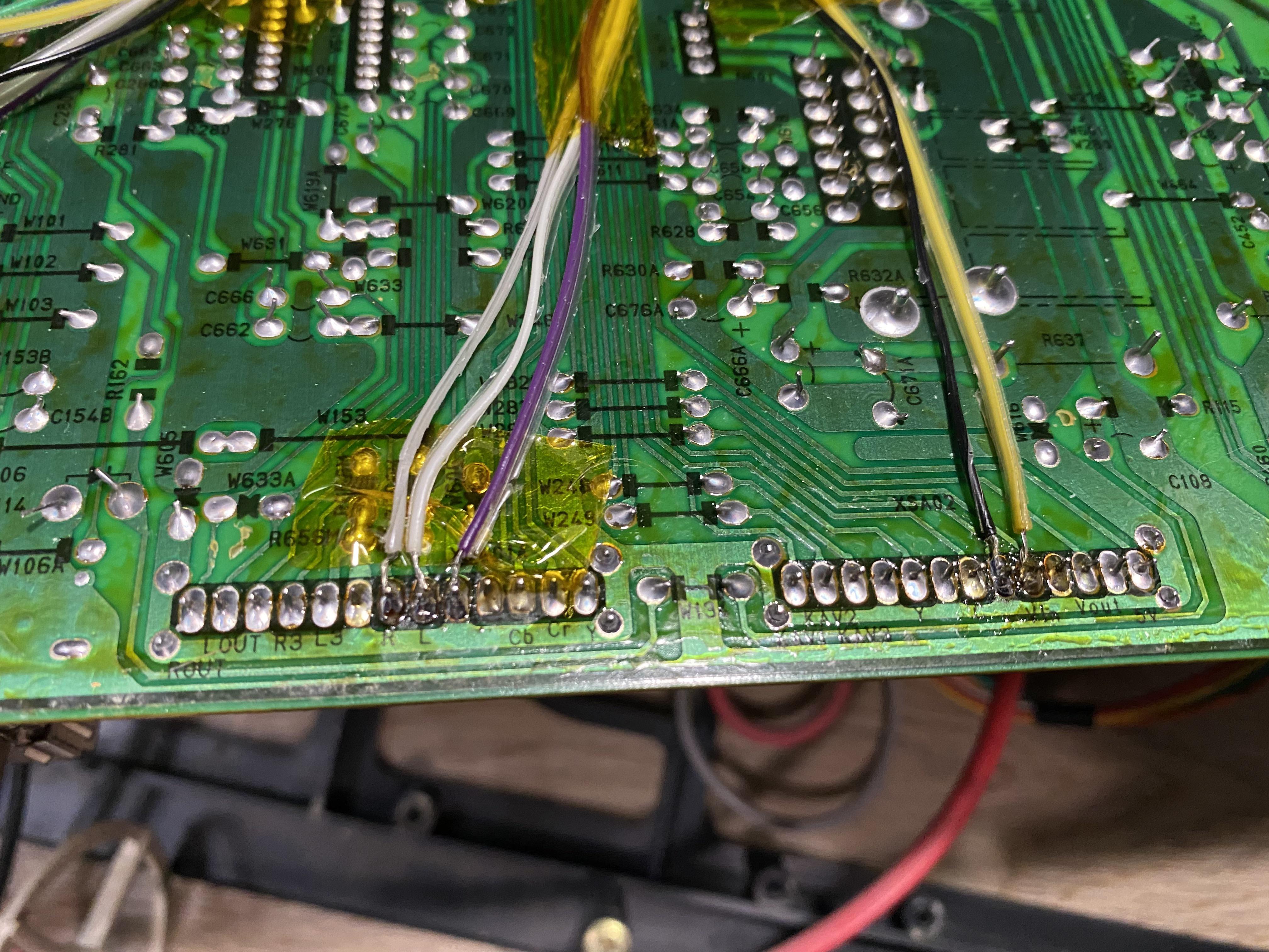
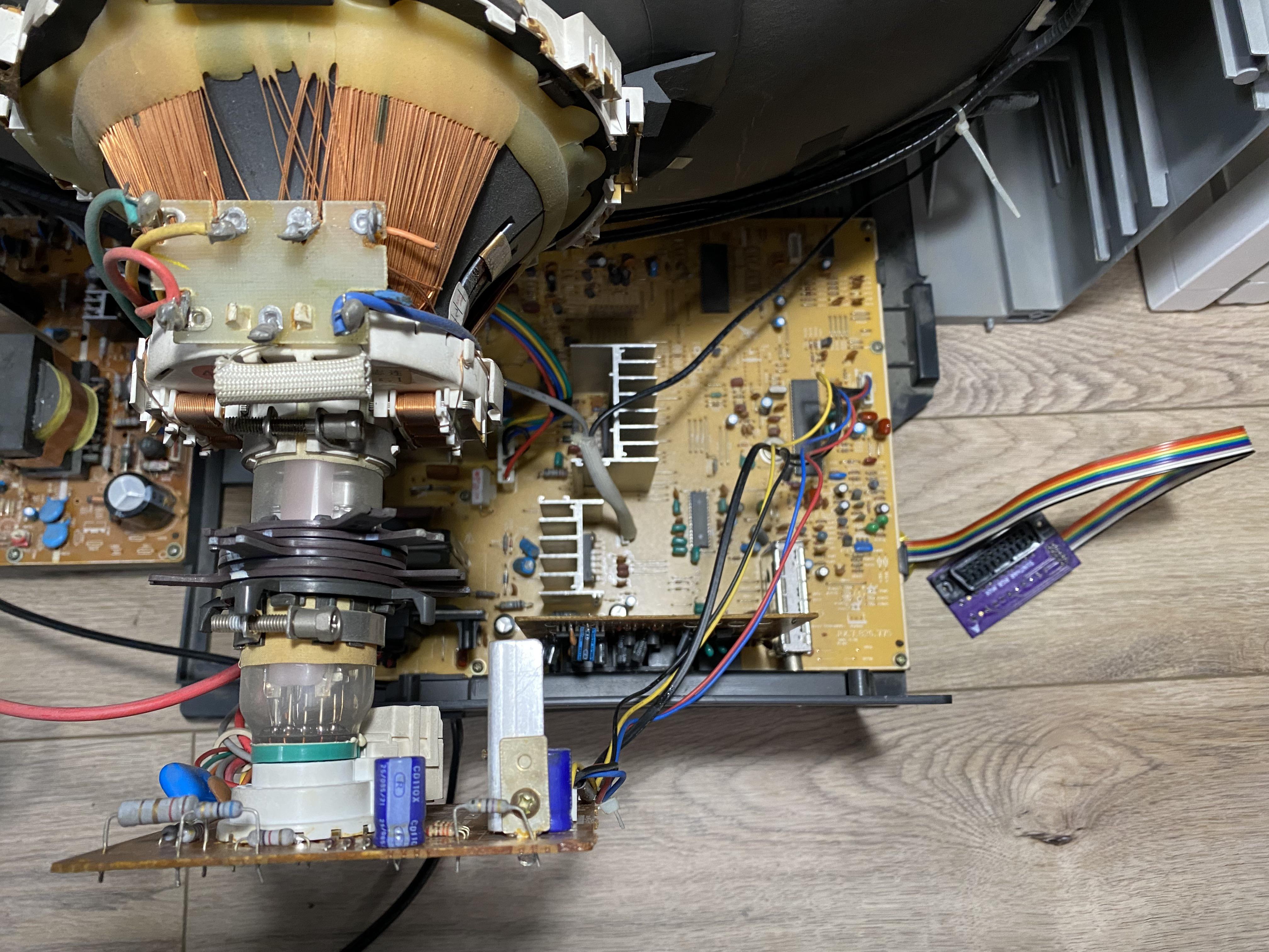
Overall mod 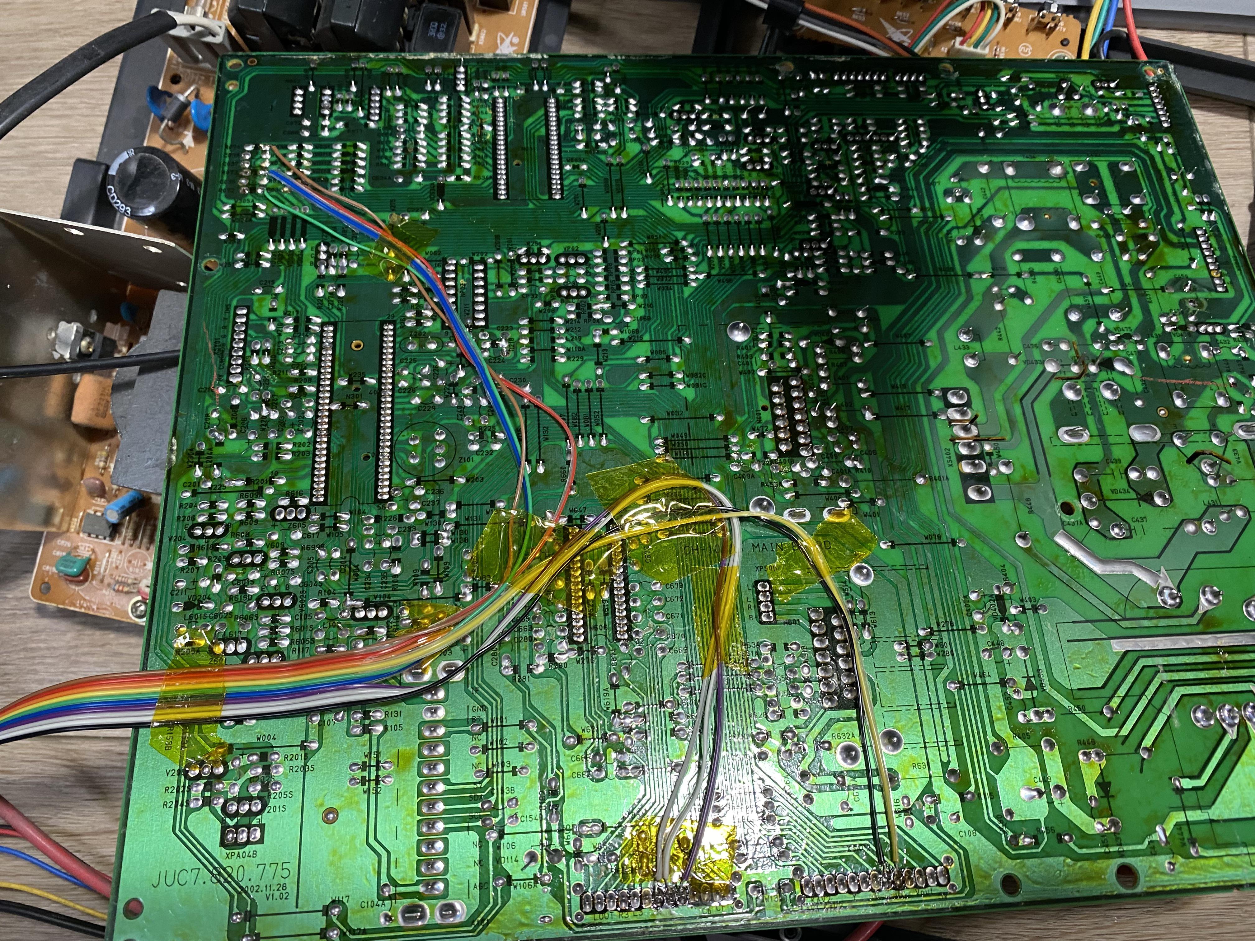
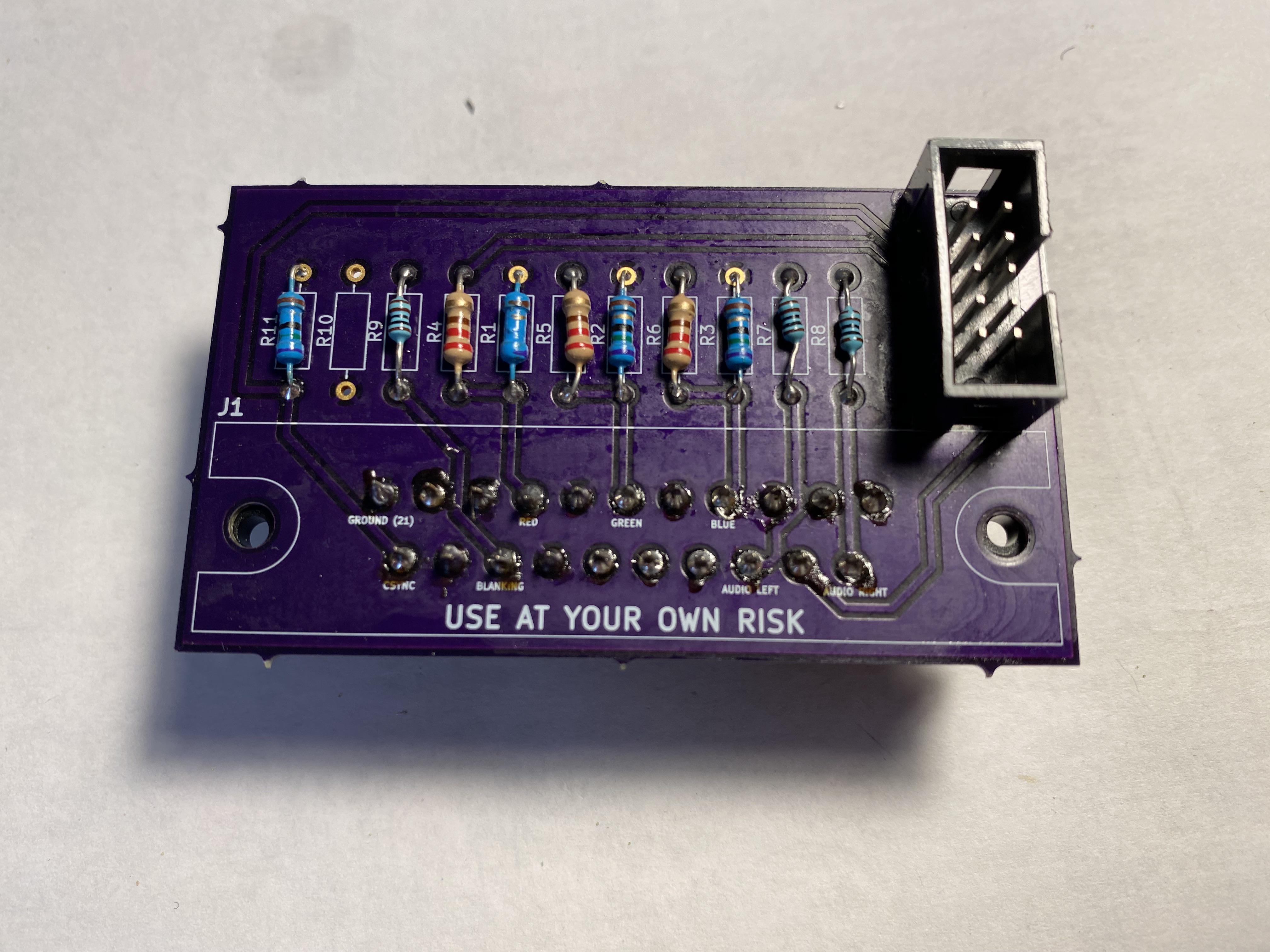
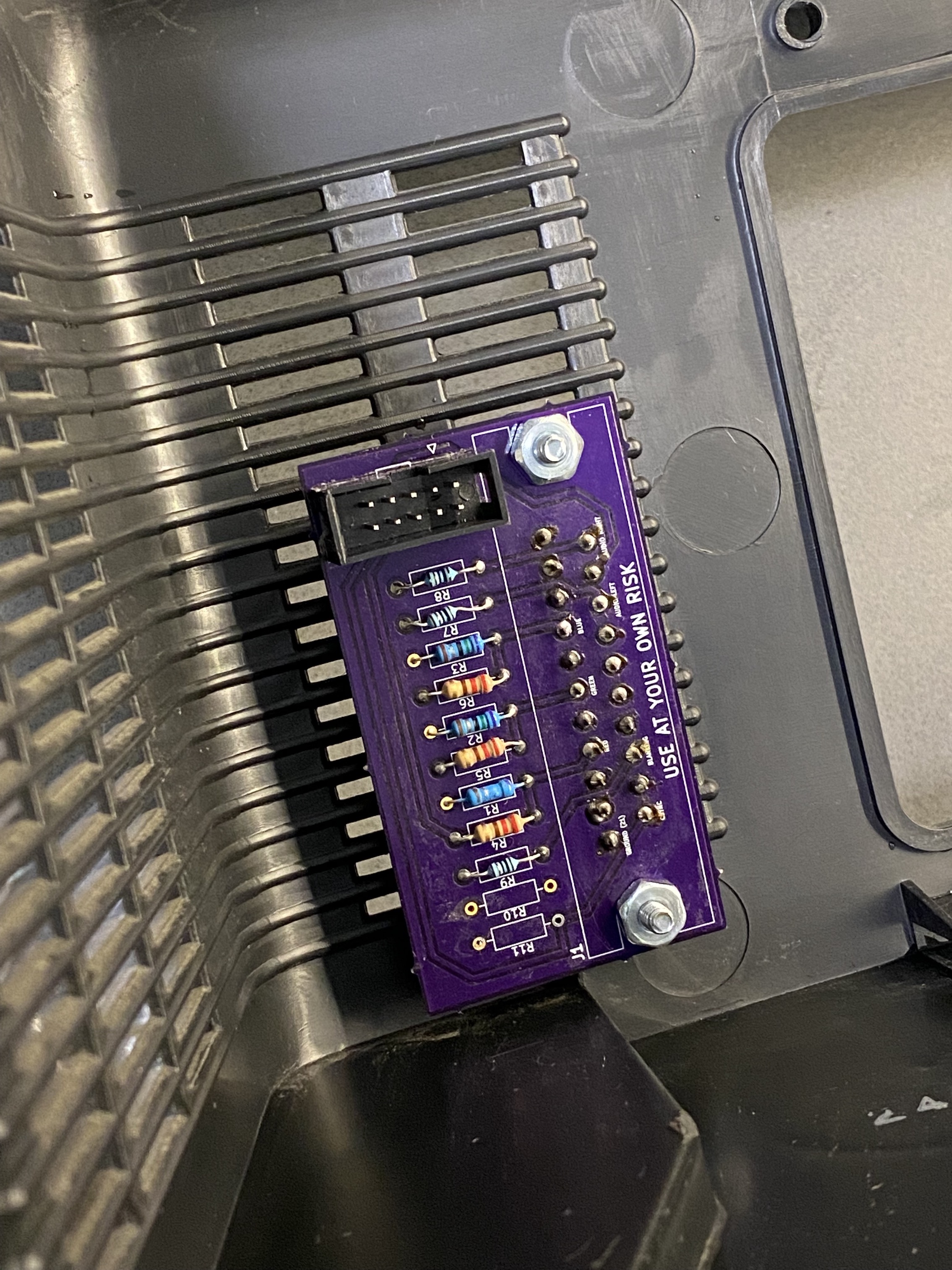
STEP 3: Build your mux circuit
This mod uses the RGB mux board. This is optional, but will make your mod easier and stable. You can also create the circuit presented in the schematics above without the board. Please also checkout the mux calculator to play with your own values.
| Component | Value |
|---|---|
| RGB/OSD inline resistor (chassis) | 1.8kΩ |
| Removed RGB/OSD resistor (chassis) | 330Ω |
| RGB termination (R1, R2, R3) | 75Ω |
| RGB inline (R4, R5, R6) | 220Ω |
| Audio LR (R7, R8) | 1kΩ |
| Diode (R9) | 1N4148 |
| Blanking Ground Resistor (R10) | open |
| Blanking Resistor (R11) | 1kΩ |
Compatible mux boards: RGB MUX BOARD KIT 1.4C, RGB MUX BOARD KIT 1.4B
What you see below is the earlier version of the mux board. Newer boards should work similarly.
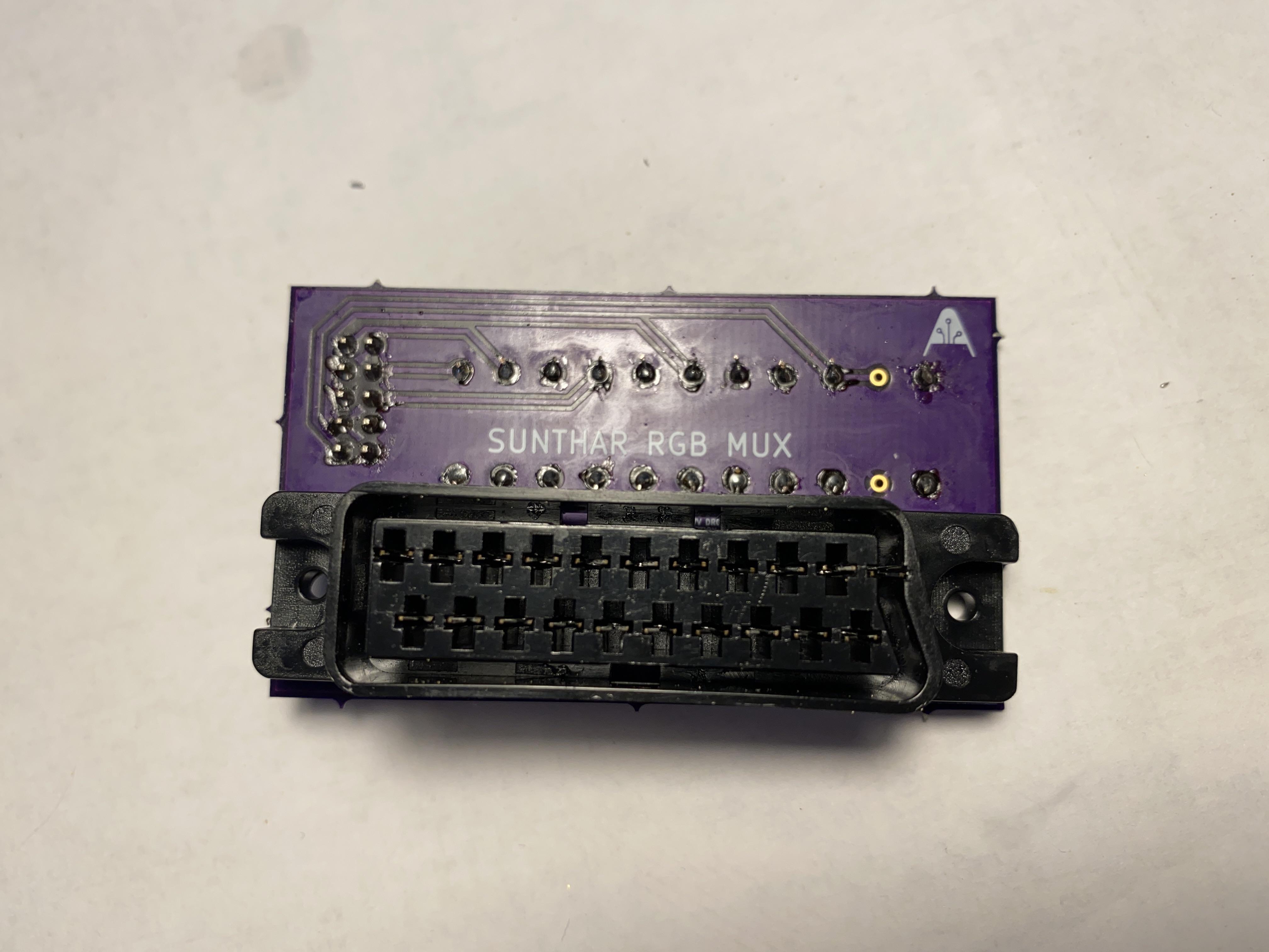
STEP 4: Attach the female SCART connector to TV
Creating a SCART cutout and mounting it is an art. I have a dedicated section for it.
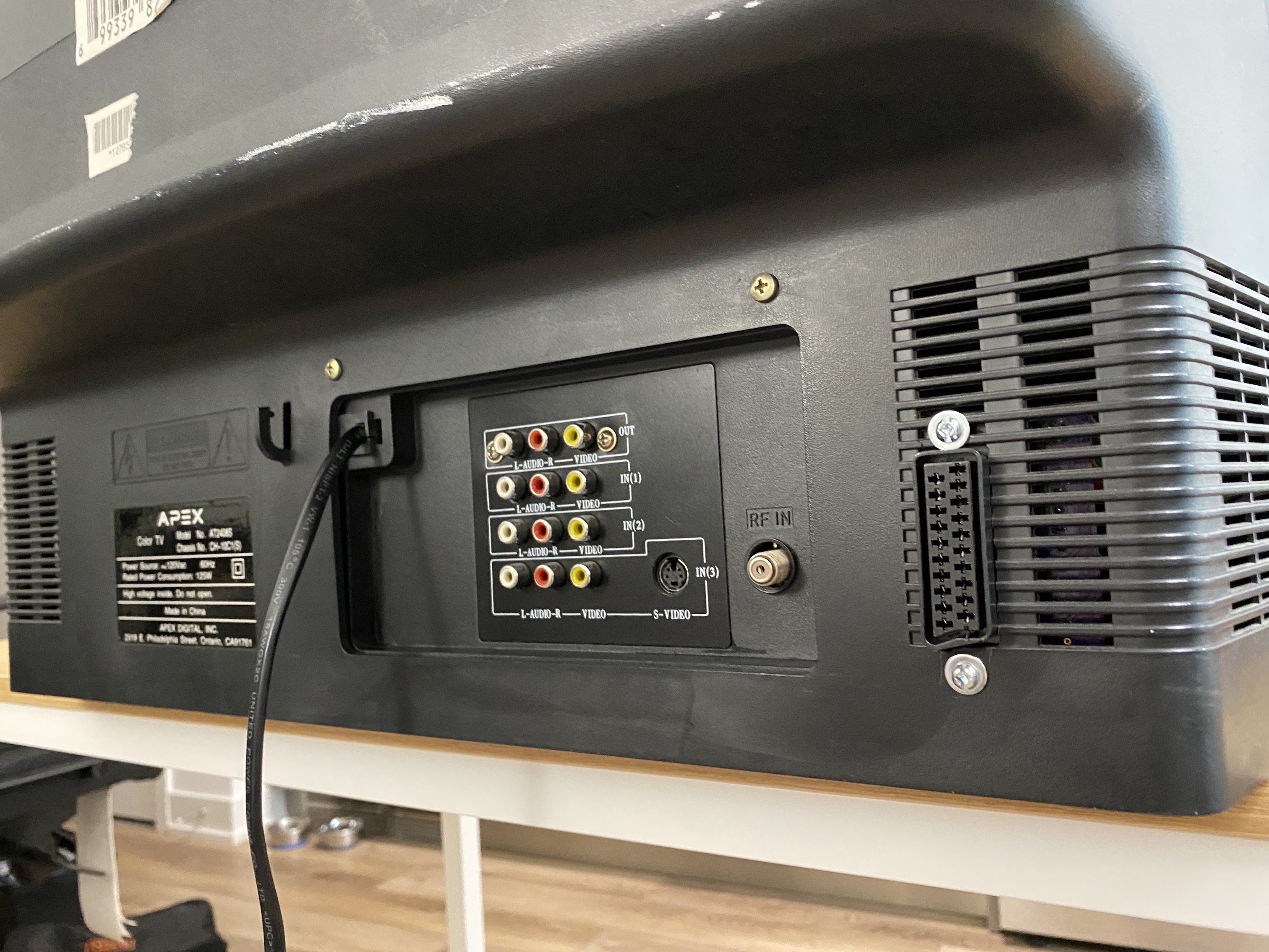
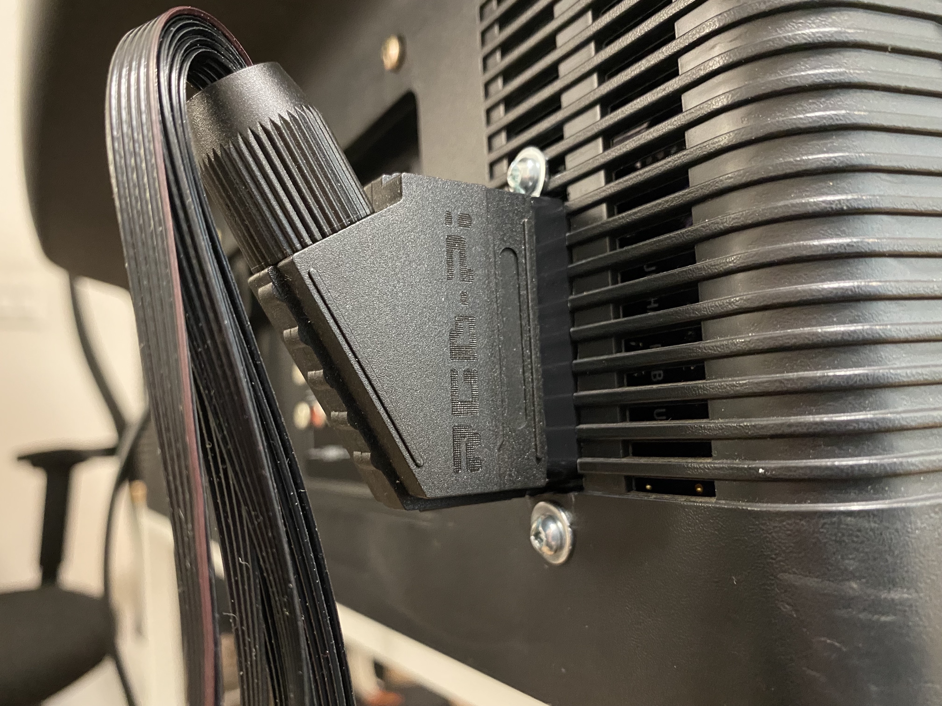
How to create and mount a SCART female plug?
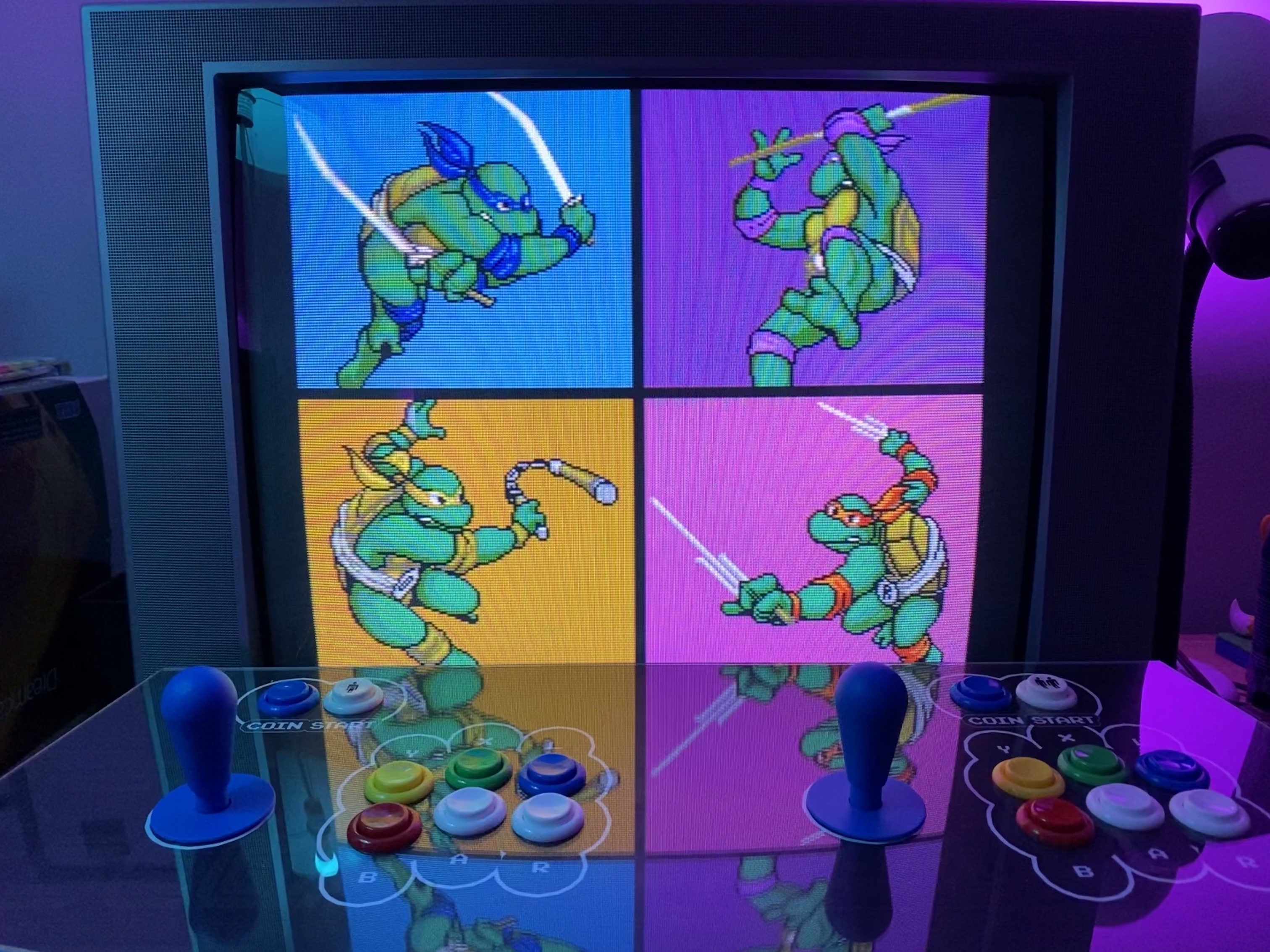

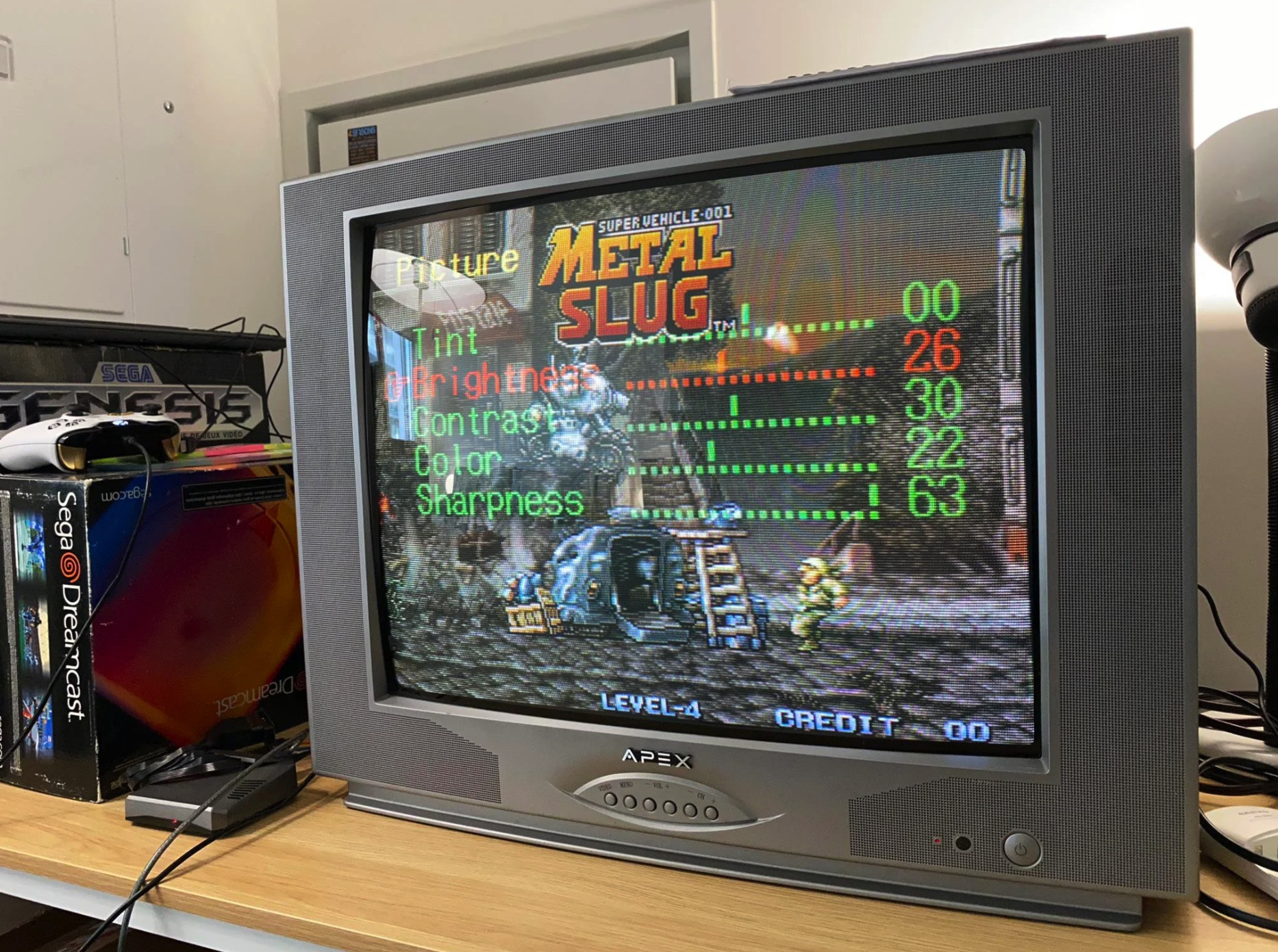
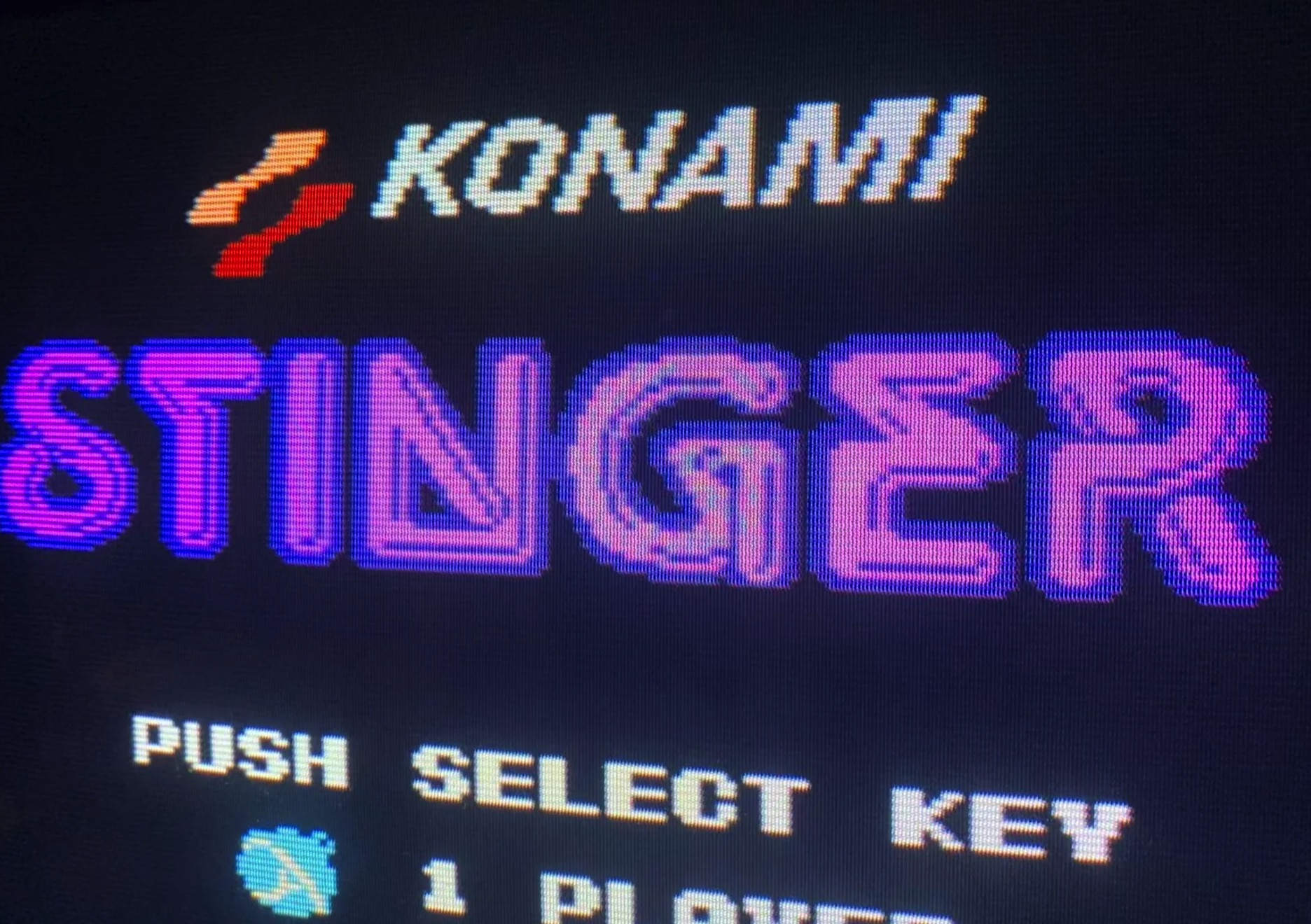
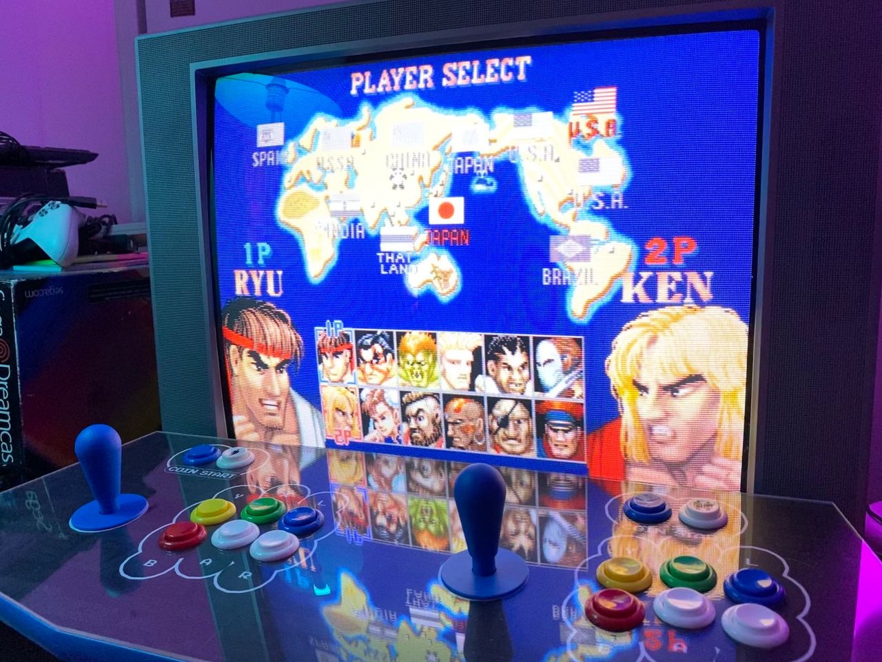
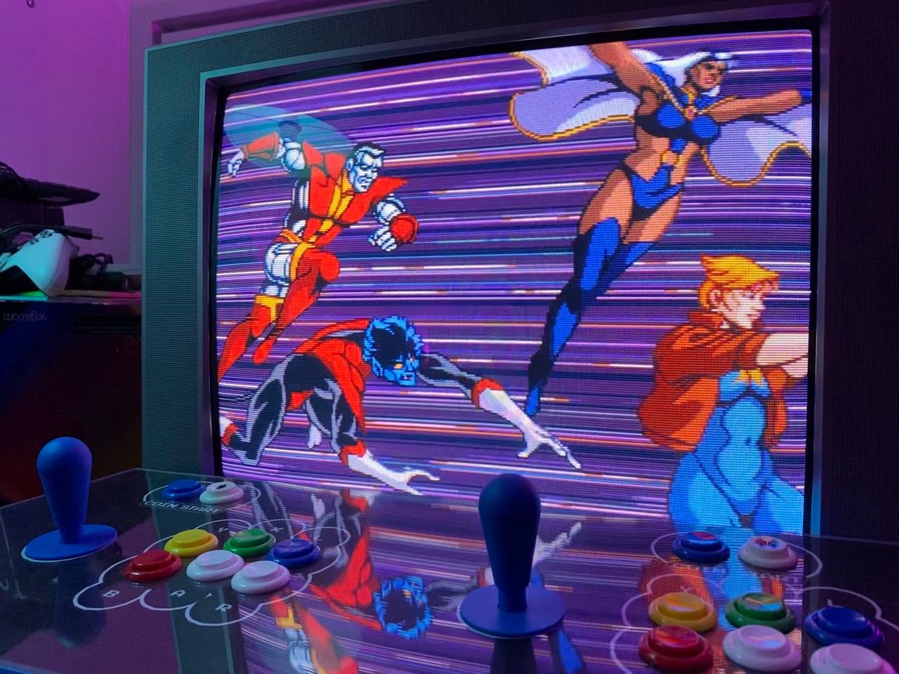
Pictures
Reference Photos